EP3436655B1 - Verknüpfungsverbinder - Google Patents
Verknüpfungsverbinder Download PDFInfo
- Publication number
- EP3436655B1 EP3436655B1 EP17706921.8A EP17706921A EP3436655B1 EP 3436655 B1 EP3436655 B1 EP 3436655B1 EP 17706921 A EP17706921 A EP 17706921A EP 3436655 B1 EP3436655 B1 EP 3436655B1
- Authority
- EP
- European Patent Office
- Prior art keywords
- link
- link connector
- links
- connector system
- upper portion
- Prior art date
- Legal status (The legal status is an assumption and is not a legal conclusion. Google has not performed a legal analysis and makes no representation as to the accuracy of the status listed.)
- Active
Links
Images


Classifications
-
- F—MECHANICAL ENGINEERING; LIGHTING; HEATING; WEAPONS; BLASTING
- F16—ENGINEERING ELEMENTS AND UNITS; GENERAL MEASURES FOR PRODUCING AND MAINTAINING EFFECTIVE FUNCTIONING OF MACHINES OR INSTALLATIONS; THERMAL INSULATION IN GENERAL
- F16B—DEVICES FOR FASTENING OR SECURING CONSTRUCTIONAL ELEMENTS OR MACHINE PARTS TOGETHER, e.g. NAILS, BOLTS, CIRCLIPS, CLAMPS, CLIPS OR WEDGES; JOINTS OR JOINTING
- F16B7/00—Connections of rods or tubes, e.g. of non-circular section, mutually, including resilient connections
- F16B7/22—Connections of rods or tubes, e.g. of non-circular section, mutually, including resilient connections using hooks or like elements
-
- E—FIXED CONSTRUCTIONS
- E21—EARTH OR ROCK DRILLING; MINING
- E21B—EARTH OR ROCK DRILLING; OBTAINING OIL, GAS, WATER, SOLUBLE OR MELTABLE MATERIALS OR A SLURRY OF MINERALS FROM WELLS
- E21B19/00—Handling rods, casings, tubes or the like outside the borehole, e.g. in the derrick; Apparatus for feeding the rods or cables
- E21B19/02—Rod or cable suspensions
-
- F—MECHANICAL ENGINEERING; LIGHTING; HEATING; WEAPONS; BLASTING
- F16—ENGINEERING ELEMENTS AND UNITS; GENERAL MEASURES FOR PRODUCING AND MAINTAINING EFFECTIVE FUNCTIONING OF MACHINES OR INSTALLATIONS; THERMAL INSULATION IN GENERAL
- F16B—DEVICES FOR FASTENING OR SECURING CONSTRUCTIONAL ELEMENTS OR MACHINE PARTS TOGETHER, e.g. NAILS, BOLTS, CIRCLIPS, CLAMPS, CLIPS OR WEDGES; JOINTS OR JOINTING
- F16B45/00—Hooks; Eyes
- F16B45/06—Hooks with two symmetrically-pivoting hook parts within the same locking cavity
Definitions
- Embodiments of this disclosure relate to a link connector system connecting links together.
- Links are used to connect a variety of rig equipment together. For example, links are used to connect a top drive/traveling block with an elevator. The links are used in a set of two. Depending on the rig operation, the length or the size (or load rating) of the set of links that is needed often changes. Thus multiple sets of links of various lengths are required. The multiple sets of links, however, can take up a significant amount of space on a rig, which is very limited.
- FR 3002 156 discloses a snap hook comprising an opening and a pivot pin which forms a clipping area.
- US 1,709,235 describes an S-link connection device having hooks and gates.
- US 2006/162138 relates to a rope hook with pivoting levers.
- US 582,780 describes a snap hook comprising a body defining two hooks and spring tongues.
- a link connector system for connecting a variety of rig equipment together comprises: a first link; a second link; and a link connector comprising: a body having an upper portion and a lower portion; a first blocking member pivotably coupled to the upper portion of the body by a pin member wherein an eyelet of the first link is secured to the upper portion of the body by the first blocking member; and a second blocking member pivotably coupled to the lower portion of the body by a pin member wherein an eyelet of the second link is secured to the lower portion of the body by the second blocking member, wherein the first and second blocking members are movable away from the body into an open position position to secure the eyelets and moveable toward the body into a closed position to secure the eyelets, and wherein when in the closed position, the link connector forms an 8 shape.
- Figure 1 illustrates three different links 10, 20, 30, each having a different length L, which may be used to connect a variety of rig equipment together.
- the links 10, 20, 30 are only exemplary as other lengths may be used with the embodiments described herein. Although only one link 10, 20, 30 of each length is shown and can be used with the embodiments described herein, the links 10, 20, 30 are generally used in a set of two links. Any combination or number of links 10, 20, 30 can be connected together using one or more link connectors 200 as further described below to form a desired length of links, which can reduce the total number of links that need to be stored on a rig and thereby reduce the amount of rig space taken up by the links.
- Figure 2 illustrates a first set of links 100a and a second set of links 100b connected together by two separate link connectors 200. Each link connector 200 connects two separate links together.
- the first and second set of links 100a, 100b are supporting an elevator 300.
- the first and second set of links 100a,100b can be used to support any other type of tubular handling device or rig equipment.
- each link of the first and second set of links 100a, 100b include an upper eyelet 110 disposed at one end of a body portion 130, and a lower eyelet 120 disposed at an opposite end of the body portion 130.
- the lower eyelets 120 of the first set of links 100a are coupled to the upper portion of the link connectors 200, while the upper eyelets 110 of the second set of links 100b are coupled to the lower portion of the link connectors 200.
- the lower eyelets 120 of the second set of links 100b are coupled to the elevator 300.
- Figures 3A and 3B illustrate one link connector 200 in an open and closed position, according to one embodiment.
- the link connector 200 is configured to connect two separate links together.
- the link connector 200 has a body 210, a first blocking member 220, and a second blocking member 230.
- the body 210 is generally "S" shaped but may be formed in other shapes.
- the first blocking member 220 is pivotably coupled at one end 221 to an upper portion of the body 210, such as by a pin member.
- the second end 222 of the first blocking member 220 can be moved (e.g. rotated) away from and out of engagement with the body 210 to allow insertion or removal of an eyelet (such as the lower eyelets 120 of the first set of links 100a shown in Figure 2 ) into or from an upper opening 223 of the link connector 200.
- an eyelet such as the lower eyelets 120 of the first set of links 100a shown in Figure 2
- the second end 222 of the first blocking member 220 In the closed position, the second end 222 of the first blocking member 220 can be moved (e.g. rotated) toward and into engagement with the body 210 to prevent and secure the eyelet from falling out of the upper opening 223 of the link connector 200.
- the second blocking member 230 is pivotably coupled at one end 231 to a lower portion of the body 210, such as by a pin member.
- the second end 232 of the second blocking member 230 can be moved (e.g. rotated) away from and out of engagement with the body 210 to allow insertion or removal of an eyelet (such as the upper eyelets 110 of the second set of links 100b shown in Figure 2 ) into or from a lower opening 233 of the link connector 200.
- an eyelet such as the upper eyelets 110 of the second set of links 100b shown in Figure 2
- the second end 232 of the second blocking member 230 In the closed position, the second end 232 of the second blocking member 230 can be moved (e.g. rotated) toward and into engagement with the body 210 to prevent and secure the eyelet from falling out of the lower opening 233 of the link connector 200.
- the first and/or second blocking members 220, 230 may be locked in either the open or closed position.
- the second end 222, 223 of the first and second blocking members 220, 230 may be secured to the body 210 in the closed position by a pin member disposed through corresponding openings formed in the blocking members 220, 230 and the body 210.
- the link connector 200 When complete and assembled in the closed position, the link connector 200 generally has an "8" shape, which enables a heavy load capacity.
- the center of gravity of the link connector 200 may be in the middle of the "8" shape to enable a balanced and vertical hanging of links.
- the first and second blocking members 220, 230 may support and carry any load to enable the closed "8" shape link connector 200.
- Figure 4 illustrates the link connectors 200 in the closed position connecting the first and second set of links 100a, 100b together, which connect the elevator 300 to a tubular handling device 400, such as a top drive and/or a traveling block.
- a tubular handling device 400 such as a top drive and/or a traveling block.
- Figure 5 illustrates an enlarged view of one link connector 200 of Figure 4 , and cross sectional portions 240, 250, 260 across section line A-A of the body 210 of the link connector 200, according to one embodiment.
- the cross sectional portion 260 is substantially the same as the cross section portion 240 but turned upside down.
- a lower surface 241 of the upper cross sectional portion 240 of the body 210 is rounded and/or has a certain radius depending on a desired load rating.
- the lower surface 241 is in contact with the lower eyelet 120.
- An upper surface 261 of the lower cross sectional portion 260 of the body 210 is rounded and/or has a certain radius depending on a desired load rating.
- the upper surface 261 is in contact with the upper eyelet 110.
- the middle cross sectional portion 250 of the body 210 may have substantially flat surfaces.
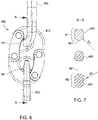
- Figure 6 illustrates an enlarged view of one link connector 400
- Figure 7 illustrates cross sectional portions 440, 450, 460 across section line A-A of a body 410 of the link connector 400, according to one embodiment.
- the link connector 400 is similar to the link connector 200 with one difference being that the upper portion of the body 410 of the link connector 400 is configured to support one size (or load rating) of a link 480 at one end while the lower portion of the body 410 is configured to support a different size (or load rating) of another link 490 at the opposite end.
- the geometry of the body 410 is configured to allow the change over from one size (or load rating) of link to a different size (or load rating) of link while using the same link connector 400.
- the profile of the upper cross sectional portion 440 of the body 410 has a height H1 and a lower surface 441 with a radius R1 configured to support a desired size (or load rating) of link, such as a 500 ton link.
- the profile of the lower cross sectional portion 460 of the body 410 has a height H2 and an upper surface 461 with a radius R2 configured to support a desired size (or load rating) of link, such as a 350 ton link.
- the lower surface 441 contacts the eyelet of the link 480 and the upper surface 461 contacts the eyelet of the link 490.
- the middle cross sectional portion 450 of the body 410 may have substantially flat upper and lower surfaces.
- the height H1 and/or the radius R1 of the upper cross sectional portion 440 is different (e.g. larger or smaller) than the height H2 and/or the radius R2, respectively, of the lower cross sectional portion 460 so that the link connector 410 can support a link at one end that has a larger or smaller size (or load rating) than the link being supported at the opposite end. In this manner, only one pair of links and link connectors 410 would have to be added when it is desired to switch out links to a larger or smaller size (or load rating), compared to having to switch out both pairs of links.
Landscapes
- Engineering & Computer Science (AREA)
- General Engineering & Computer Science (AREA)
- Mechanical Engineering (AREA)
- Mining & Mineral Resources (AREA)
- Life Sciences & Earth Sciences (AREA)
- Geology (AREA)
- Fluid Mechanics (AREA)
- Environmental & Geological Engineering (AREA)
- Physics & Mathematics (AREA)
- General Life Sciences & Earth Sciences (AREA)
- Geochemistry & Mineralogy (AREA)
- Lift-Guide Devices, And Elevator Ropes And Cables (AREA)
- Seats For Vehicles (AREA)
Claims (11)
- Ein Verbindungsanschlusssystem zum Verbinden einer Vielzahl von Bohrturmausrüstungen miteinander, wobei das System Folgendes umfasst:eine erste Verbindung (100a),eine zweite Verbindung (100b) undeinen Verbindungsanschluss (200, 400), der Folgendes umfasst:einen Körper (210, 410) mit einem oberen Teil und einem unteren Teil;ein erstes Blockierungselement (220), das schwenkbar mit dem oberen Teil des Körpers (210, 410) durch ein Stiftelement gekoppelt ist, wobei eine Öse (120, 480) der ersten Verbindung durch das erste Blockierungselement (220) am oberen Teil des Körpers (210, 410) befestigt ist, undein zweites Blockierungselement (230), das schwenkbar mit dem unteren Teil des Körpers (210, 410) durch ein Stiftelement gekoppelt ist, wobei eine Öse (110, 490) der zweiten Verbindung durch das zweite Blockierungselement (230) am unteren Teil des Körpers (210, 410) befestigt ist, wobei das erste und das zweite Blockierungselement (220, 230) vom Körper (210, 410) weg in eine offene Position bewegt werden können, um das Einführen oder Entfernen der Ösen (120, 480, 110, 490) zu ermöglichen, und zum Körper (210, 410) hin in eine geschlossene Position bewegt werden können, um die Ösen (120, 480, 110, 490) zu sichern, und wobei der Verbindungsanschluss (200, 400) in der geschlossenen Position eine Acht bildet.
- Das Verbindungsanschlusssystem nach Anspruch 1, wobei sich ein Schwerpunkt des Verbindungsanschlusses (200, 400) in der Mitte der Acht befindet.
- Das Verbindungsanschlusssystem nach Anspruch 1, wobei die Öse (120, 480) der ersten Verbindung eine abgerundete Oberfläche (241, 441) des oberen Teils des Körpers (210, 410) berührt.
- Das Verbindungsanschlusssystem nach Anspruch 1, wobei die Öse (110, 490) der zweiten Verbindung eine abgerundete Oberfläche (261, 461) des unteren Teils des Körpers (210, 410) berührt.
- Das Verbindungsanschlusssystem nach Anspruch 1, wobei die erste Verbindung und die zweite Verbindung (100a, 100b) dieselbe Länge haben.
- Das Verbindungsanschlusssystem nach Anspruch 1, wobei die erste Verbindung und die zweite Verbindung (100a, 100b) unterschiedliche Längen haben.
- Das Verbindungsanschlusssystem nach Anspruch 1, wobei ein Querschnitt des oberen Teils des Körpers (210, 410) im Wesentlichen derselbe ist wie ein Querschnitt des unteren Teils des Körpers (210, 410).
- Das Verbindungsanschlusssystem nach Anspruch 1, wobei der obere Teil des Körpers (210, 410) so konfiguriert ist, dass er eine Verbindung stützt, die eine Größe hat, die sich von einer Größe einer Verbindung unterscheidet, die durch den unteren Teil des Körpers (210, 410) gestützt wird.
- Das Verbindungsanschlusssystem nach Anspruch 1, wobei der obere Teil des Körpers (210, 410) so konfiguriert ist, dass er eine Verbindung stützt, die eine Tragfähigkeit hat, die sich von einer Tragfähigkeit einer Verbindung unterscheidet, die durch den unteren Teil des Körpers (210, 410) gestützt wird.
- Das Verbindungsanschlusssystem nach Anspruch 1, wobei ein Profil eines Querschnitts des oberen Teils des Körpers (210, 410) eine Höhe (H1) hat, die sich von einer Höhe (H2) eines Profils eines Querschnitts des unteren Teils des Körpers (210, 410) unterscheidet, wenn es über denselben Abschnitt durch den Körper erstellt wird.
- Das Verbindungsanschlusssystem nach Anspruch 1, wobei eine untere Oberfläche (241, 441) eines Profils eines Querschnitts des oberen Teils des Körpers (210, 410) einen Radius hat, der sich von einem Radius einer oberen Oberfläche (261, 461) eines Profils eines Querschnitts des unteren Teils des Körpers (210, 410) unterscheidet, wenn es über dieselbe Schnittlinie durch den Körper erstellt wird.
Applications Claiming Priority (2)
| Application Number | Priority Date | Filing Date | Title |
|---|---|---|---|
| US201662314559P | 2016-03-29 | 2016-03-29 | |
| PCT/US2017/016808 WO2017172048A1 (en) | 2016-03-29 | 2017-02-07 | Link connector |
Publications (2)
| Publication Number | Publication Date |
|---|---|
| EP3436655A1 EP3436655A1 (de) | 2019-02-06 |
| EP3436655B1 true EP3436655B1 (de) | 2022-11-02 |
Family
ID=58108733
Family Applications (1)
| Application Number | Title | Priority Date | Filing Date |
|---|---|---|---|
| EP17706921.8A Active EP3436655B1 (de) | 2016-03-29 | 2017-02-07 | Verknüpfungsverbinder |
Country Status (3)
| Country | Link |
|---|---|
| US (1) | US10502249B2 (de) |
| EP (1) | EP3436655B1 (de) |
| WO (1) | WO2017172048A1 (de) |
Families Citing this family (6)
| Publication number | Priority date | Publication date | Assignee | Title |
|---|---|---|---|---|
| US10641305B2 (en) * | 2017-03-28 | 2020-05-05 | Forum Us, Inc. | Link extension connector |
| EP3784912A4 (de) | 2018-04-27 | 2021-12-22 | Noetic Technologies Inc. | Verstellbare bügelverlängerung |
| CA3059916C (en) * | 2018-10-25 | 2023-06-20 | Kevin Truesdell | Locking snap-hook for use with linkless attachment |
| USD925612S1 (en) * | 2019-03-14 | 2021-07-20 | Forum Us, Inc. | Pipe lifting elevator body |
| WO2023017387A1 (en) * | 2021-08-11 | 2023-02-16 | Weatherford Technology Holdings, Llc | Elevator for tubular handling in well operations |
| US20250020030A1 (en) | 2023-07-13 | 2025-01-16 | Frank's International, Llc | Quick bail system |
Family Cites Families (11)
| Publication number | Priority date | Publication date | Assignee | Title |
|---|---|---|---|---|
| US582780A (en) * | 1897-05-18 | Reuben c | ||
| US1709235A (en) | 1927-01-14 | 1929-04-16 | Ernest J Shaffer | Connecting device |
| US2357478A (en) * | 1943-07-16 | 1944-09-05 | Harry O Koch | Snatch link |
| US3461666A (en) * | 1967-10-17 | 1969-08-19 | Byron Jackson Inc | Elevator link and process of making the same |
| US6336260B1 (en) * | 2000-07-06 | 2002-01-08 | Basecamp Innovations, Ltd. | Gated rigging plate |
| US6679333B2 (en) * | 2001-10-26 | 2004-01-20 | Canrig Drilling Technology, Ltd. | Top drive well casing system and method |
| JP2004123378A (ja) | 2002-08-02 | 2004-04-22 | Niichi:Kk | ロープ等掛け具 |
| US6832658B2 (en) * | 2002-10-11 | 2004-12-21 | Larry G. Keast | Top drive system |
| FR3002156A1 (fr) | 2013-02-21 | 2014-08-22 | Norbert Louis Apicella | Double mousqueton |
| WO2015038509A1 (en) * | 2013-09-10 | 2015-03-19 | ACCO Brands Corporation | Carabiner including a lock mechanism |
| US9556690B1 (en) | 2015-05-13 | 2017-01-31 | Alpha Dog Oilfield Tools | Elevator link extension systems |
-
2017
- 2017-02-07 EP EP17706921.8A patent/EP3436655B1/de active Active
- 2017-02-07 WO PCT/US2017/016808 patent/WO2017172048A1/en not_active Ceased
- 2017-02-07 US US15/426,221 patent/US10502249B2/en active Active
Also Published As
| Publication number | Publication date |
|---|---|
| US10502249B2 (en) | 2019-12-10 |
| EP3436655A1 (de) | 2019-02-06 |
| US20170284438A1 (en) | 2017-10-05 |
| WO2017172048A1 (en) | 2017-10-05 |
Similar Documents
| Publication | Publication Date | Title |
|---|---|---|
| EP3436655B1 (de) | Verknüpfungsverbinder | |
| US10641305B2 (en) | Link extension connector | |
| WO2019092687A1 (en) | Swivel shackle sets | |
| EP3512058A1 (de) | Kabelschutzkette | |
| US20150271945A1 (en) | Cable management device | |
| US20090044387A1 (en) | Hook and connector device | |
| US11487072B2 (en) | Articulating optical fiber guide system | |
| KR102267159B1 (ko) | 터미널 커넥터 | |
| US3083991A (en) | Rope thimble | |
| US20180305185A1 (en) | Suspension ring for multistrand lifting tackle | |
| US20190077543A1 (en) | Multi-height container | |
| CA3012039C (en) | Chain link for an energy guiding chain and an energy guiding chain | |
| CN110630689A (zh) | 一种长距离防塌腰拖链 | |
| US9865975B2 (en) | Hinged connector door assembly | |
| US10381769B2 (en) | Female connector plug including a lock | |
| KR100650745B1 (ko) | 이단 선반 구조 | |
| CN204835017U (zh) | 免打线网络信息模块 | |
| KR101350982B1 (ko) | 케이블 체인 | |
| KR200491244Y1 (ko) | 원터치로 변형 가능한 휴대용 가방걸이 | |
| KR102255500B1 (ko) | 커넥터 레버 및 그를 포함하는 커넥터 | |
| EP3838785A1 (de) | Behälter mit einem ballenarm mit einem konischen gelenkbolzen | |
| JP4084811B2 (ja) | スライダ離脱可能な保持具 | |
| EP3371401A1 (de) | Scharnier | |
| US9920814B2 (en) | Clevis structure | |
| JP2022516656A (ja) | フロントガラスワイパーブレードアダプター |
Legal Events
| Date | Code | Title | Description |
|---|---|---|---|
| STAA | Information on the status of an ep patent application or granted ep patent |
Free format text: STATUS: UNKNOWN |
|
| STAA | Information on the status of an ep patent application or granted ep patent |
Free format text: STATUS: THE INTERNATIONAL PUBLICATION HAS BEEN MADE |
|
| PUAI | Public reference made under article 153(3) epc to a published international application that has entered the european phase |
Free format text: ORIGINAL CODE: 0009012 |
|
| STAA | Information on the status of an ep patent application or granted ep patent |
Free format text: STATUS: REQUEST FOR EXAMINATION WAS MADE |
|
| 17P | Request for examination filed |
Effective date: 20180914 |
|
| AK | Designated contracting states |
Kind code of ref document: A1 Designated state(s): AL AT BE BG CH CY CZ DE DK EE ES FI FR GB GR HR HU IE IS IT LI LT LU LV MC MK MT NL NO PL PT RO RS SE SI SK SM TR |
|
| AX | Request for extension of the european patent |
Extension state: BA ME |
|
| RIN1 | Information on inventor provided before grant (corrected) |
Inventor name: STOLDT, FREDERIK Inventor name: VIERKE, ANDRE Inventor name: CHILDRESS, LAWRENCE E., II |
|
| DAV | Request for validation of the european patent (deleted) | ||
| DAX | Request for extension of the european patent (deleted) | ||
| GRAP | Despatch of communication of intention to grant a patent |
Free format text: ORIGINAL CODE: EPIDOSNIGR1 |
|
| STAA | Information on the status of an ep patent application or granted ep patent |
Free format text: STATUS: GRANT OF PATENT IS INTENDED |
|
| INTG | Intention to grant announced |
Effective date: 20220519 |
|
| GRAS | Grant fee paid |
Free format text: ORIGINAL CODE: EPIDOSNIGR3 |
|
| GRAA | (expected) grant |
Free format text: ORIGINAL CODE: 0009210 |
|
| STAA | Information on the status of an ep patent application or granted ep patent |
Free format text: STATUS: THE PATENT HAS BEEN GRANTED |
|
| AK | Designated contracting states |
Kind code of ref document: B1 Designated state(s): AL AT BE BG CH CY CZ DE DK EE ES FI FR GB GR HR HU IE IS IT LI LT LU LV MC MK MT NL NO PL PT RO RS SE SI SK SM TR |
|
| REG | Reference to a national code |
Ref country code: GB Ref legal event code: FG4D |
|
| REG | Reference to a national code |
Ref country code: CH Ref legal event code: EP Ref country code: AT Ref legal event code: REF Ref document number: 1528884 Country of ref document: AT Kind code of ref document: T Effective date: 20221115 |
|
| REG | Reference to a national code |
Ref country code: DE Ref legal event code: R096 Ref document number: 602017063236 Country of ref document: DE |
|
| REG | Reference to a national code |
Ref country code: IE Ref legal event code: FG4D |
|
| REG | Reference to a national code |
Ref country code: NL Ref legal event code: FP |
|
| RAP4 | Party data changed (patent owner data changed or rights of a patent transferred) |
Owner name: FORUM US, INC. |
|
| REG | Reference to a national code |
Ref country code: LT Ref legal event code: MG9D |
|
| REG | Reference to a national code |
Ref country code: NO Ref legal event code: T2 Effective date: 20221102 |
|
| REG | Reference to a national code |
Ref country code: AT Ref legal event code: MK05 Ref document number: 1528884 Country of ref document: AT Kind code of ref document: T Effective date: 20221102 |
|
| PG25 | Lapsed in a contracting state [announced via postgrant information from national office to epo] |
Ref country code: SE Free format text: LAPSE BECAUSE OF FAILURE TO SUBMIT A TRANSLATION OF THE DESCRIPTION OR TO PAY THE FEE WITHIN THE PRESCRIBED TIME-LIMIT Effective date: 20221102 Ref country code: PT Free format text: LAPSE BECAUSE OF FAILURE TO SUBMIT A TRANSLATION OF THE DESCRIPTION OR TO PAY THE FEE WITHIN THE PRESCRIBED TIME-LIMIT Effective date: 20230302 Ref country code: LT Free format text: LAPSE BECAUSE OF FAILURE TO SUBMIT A TRANSLATION OF THE DESCRIPTION OR TO PAY THE FEE WITHIN THE PRESCRIBED TIME-LIMIT Effective date: 20221102 Ref country code: FI Free format text: LAPSE BECAUSE OF FAILURE TO SUBMIT A TRANSLATION OF THE DESCRIPTION OR TO PAY THE FEE WITHIN THE PRESCRIBED TIME-LIMIT Effective date: 20221102 Ref country code: ES Free format text: LAPSE BECAUSE OF FAILURE TO SUBMIT A TRANSLATION OF THE DESCRIPTION OR TO PAY THE FEE WITHIN THE PRESCRIBED TIME-LIMIT Effective date: 20221102 Ref country code: AT Free format text: LAPSE BECAUSE OF FAILURE TO SUBMIT A TRANSLATION OF THE DESCRIPTION OR TO PAY THE FEE WITHIN THE PRESCRIBED TIME-LIMIT Effective date: 20221102 |
|
| PG25 | Lapsed in a contracting state [announced via postgrant information from national office to epo] |
Ref country code: RS Free format text: LAPSE BECAUSE OF FAILURE TO SUBMIT A TRANSLATION OF THE DESCRIPTION OR TO PAY THE FEE WITHIN THE PRESCRIBED TIME-LIMIT Effective date: 20221102 Ref country code: PL Free format text: LAPSE BECAUSE OF FAILURE TO SUBMIT A TRANSLATION OF THE DESCRIPTION OR TO PAY THE FEE WITHIN THE PRESCRIBED TIME-LIMIT Effective date: 20221102 Ref country code: LV Free format text: LAPSE BECAUSE OF FAILURE TO SUBMIT A TRANSLATION OF THE DESCRIPTION OR TO PAY THE FEE WITHIN THE PRESCRIBED TIME-LIMIT Effective date: 20221102 Ref country code: IS Free format text: LAPSE BECAUSE OF FAILURE TO SUBMIT A TRANSLATION OF THE DESCRIPTION OR TO PAY THE FEE WITHIN THE PRESCRIBED TIME-LIMIT Effective date: 20230302 Ref country code: HR Free format text: LAPSE BECAUSE OF FAILURE TO SUBMIT A TRANSLATION OF THE DESCRIPTION OR TO PAY THE FEE WITHIN THE PRESCRIBED TIME-LIMIT Effective date: 20221102 Ref country code: GR Free format text: LAPSE BECAUSE OF FAILURE TO SUBMIT A TRANSLATION OF THE DESCRIPTION OR TO PAY THE FEE WITHIN THE PRESCRIBED TIME-LIMIT Effective date: 20230203 |
|
| PG25 | Lapsed in a contracting state [announced via postgrant information from national office to epo] |
Ref country code: SM Free format text: LAPSE BECAUSE OF FAILURE TO SUBMIT A TRANSLATION OF THE DESCRIPTION OR TO PAY THE FEE WITHIN THE PRESCRIBED TIME-LIMIT Effective date: 20221102 Ref country code: RO Free format text: LAPSE BECAUSE OF FAILURE TO SUBMIT A TRANSLATION OF THE DESCRIPTION OR TO PAY THE FEE WITHIN THE PRESCRIBED TIME-LIMIT Effective date: 20221102 Ref country code: EE Free format text: LAPSE BECAUSE OF FAILURE TO SUBMIT A TRANSLATION OF THE DESCRIPTION OR TO PAY THE FEE WITHIN THE PRESCRIBED TIME-LIMIT Effective date: 20221102 Ref country code: DK Free format text: LAPSE BECAUSE OF FAILURE TO SUBMIT A TRANSLATION OF THE DESCRIPTION OR TO PAY THE FEE WITHIN THE PRESCRIBED TIME-LIMIT Effective date: 20221102 Ref country code: CZ Free format text: LAPSE BECAUSE OF FAILURE TO SUBMIT A TRANSLATION OF THE DESCRIPTION OR TO PAY THE FEE WITHIN THE PRESCRIBED TIME-LIMIT Effective date: 20221102 |
|
| REG | Reference to a national code |
Ref country code: DE Ref legal event code: R097 Ref document number: 602017063236 Country of ref document: DE |
|
| PG25 | Lapsed in a contracting state [announced via postgrant information from national office to epo] |
Ref country code: SK Free format text: LAPSE BECAUSE OF FAILURE TO SUBMIT A TRANSLATION OF THE DESCRIPTION OR TO PAY THE FEE WITHIN THE PRESCRIBED TIME-LIMIT Effective date: 20221102 Ref country code: AL Free format text: LAPSE BECAUSE OF FAILURE TO SUBMIT A TRANSLATION OF THE DESCRIPTION OR TO PAY THE FEE WITHIN THE PRESCRIBED TIME-LIMIT Effective date: 20221102 |
|
| PLBE | No opposition filed within time limit |
Free format text: ORIGINAL CODE: 0009261 |
|
| STAA | Information on the status of an ep patent application or granted ep patent |
Free format text: STATUS: NO OPPOSITION FILED WITHIN TIME LIMIT |
|
| PG25 | Lapsed in a contracting state [announced via postgrant information from national office to epo] |
Ref country code: MC Free format text: LAPSE BECAUSE OF FAILURE TO SUBMIT A TRANSLATION OF THE DESCRIPTION OR TO PAY THE FEE WITHIN THE PRESCRIBED TIME-LIMIT Effective date: 20221102 |
|
| REG | Reference to a national code |
Ref country code: CH Ref legal event code: PL |
|
| 26N | No opposition filed |
Effective date: 20230803 |
|
| REG | Reference to a national code |
Ref country code: BE Ref legal event code: MM Effective date: 20230228 |
|
| PG25 | Lapsed in a contracting state [announced via postgrant information from national office to epo] |
Ref country code: LU Free format text: LAPSE BECAUSE OF NON-PAYMENT OF DUE FEES Effective date: 20230207 Ref country code: LI Free format text: LAPSE BECAUSE OF NON-PAYMENT OF DUE FEES Effective date: 20230228 Ref country code: CH Free format text: LAPSE BECAUSE OF NON-PAYMENT OF DUE FEES Effective date: 20230228 |
|
| PG25 | Lapsed in a contracting state [announced via postgrant information from national office to epo] |
Ref country code: SI Free format text: LAPSE BECAUSE OF FAILURE TO SUBMIT A TRANSLATION OF THE DESCRIPTION OR TO PAY THE FEE WITHIN THE PRESCRIBED TIME-LIMIT Effective date: 20221102 |
|
| REG | Reference to a national code |
Ref country code: IE Ref legal event code: MM4A |
|
| PG25 | Lapsed in a contracting state [announced via postgrant information from national office to epo] |
Ref country code: IE Free format text: LAPSE BECAUSE OF NON-PAYMENT OF DUE FEES Effective date: 20230207 Ref country code: FR Free format text: LAPSE BECAUSE OF NON-PAYMENT OF DUE FEES Effective date: 20230228 |
|
| PG25 | Lapsed in a contracting state [announced via postgrant information from national office to epo] |
Ref country code: BE Free format text: LAPSE BECAUSE OF NON-PAYMENT OF DUE FEES Effective date: 20230228 |
|
| PGFP | Annual fee paid to national office [announced via postgrant information from national office to epo] |
Ref country code: GB Payment date: 20240314 Year of fee payment: 8 |
|
| PG25 | Lapsed in a contracting state [announced via postgrant information from national office to epo] |
Ref country code: IT Free format text: LAPSE BECAUSE OF FAILURE TO SUBMIT A TRANSLATION OF THE DESCRIPTION OR TO PAY THE FEE WITHIN THE PRESCRIBED TIME-LIMIT Effective date: 20221102 |
|
| PG25 | Lapsed in a contracting state [announced via postgrant information from national office to epo] |
Ref country code: BG Free format text: LAPSE BECAUSE OF FAILURE TO SUBMIT A TRANSLATION OF THE DESCRIPTION OR TO PAY THE FEE WITHIN THE PRESCRIBED TIME-LIMIT Effective date: 20221102 |
|
| PG25 | Lapsed in a contracting state [announced via postgrant information from national office to epo] |
Ref country code: BG Free format text: LAPSE BECAUSE OF FAILURE TO SUBMIT A TRANSLATION OF THE DESCRIPTION OR TO PAY THE FEE WITHIN THE PRESCRIBED TIME-LIMIT Effective date: 20221102 |
|
| PG25 | Lapsed in a contracting state [announced via postgrant information from national office to epo] |
Ref country code: CY Free format text: LAPSE BECAUSE OF FAILURE TO SUBMIT A TRANSLATION OF THE DESCRIPTION OR TO PAY THE FEE WITHIN THE PRESCRIBED TIME-LIMIT; INVALID AB INITIO Effective date: 20170207 |
|
| PG25 | Lapsed in a contracting state [announced via postgrant information from national office to epo] |
Ref country code: HU Free format text: LAPSE BECAUSE OF FAILURE TO SUBMIT A TRANSLATION OF THE DESCRIPTION OR TO PAY THE FEE WITHIN THE PRESCRIBED TIME-LIMIT; INVALID AB INITIO Effective date: 20170207 |
|
| GBPC | Gb: european patent ceased through non-payment of renewal fee |
Effective date: 20250207 |
|
| PG25 | Lapsed in a contracting state [announced via postgrant information from national office to epo] |
Ref country code: TR Free format text: LAPSE BECAUSE OF FAILURE TO SUBMIT A TRANSLATION OF THE DESCRIPTION OR TO PAY THE FEE WITHIN THE PRESCRIBED TIME-LIMIT Effective date: 20221102 |
|
| PG25 | Lapsed in a contracting state [announced via postgrant information from national office to epo] |
Ref country code: GB Free format text: LAPSE BECAUSE OF NON-PAYMENT OF DUE FEES Effective date: 20250207 |
|
| PGFP | Annual fee paid to national office [announced via postgrant information from national office to epo] |
Ref country code: NL Payment date: 20260211 Year of fee payment: 10 |
|
| PGFP | Annual fee paid to national office [announced via postgrant information from national office to epo] |
Ref country code: DE Payment date: 20260213 Year of fee payment: 10 Ref country code: NO Payment date: 20260223 Year of fee payment: 10 |