EP3436664B1 - Bohrverfahren und schachtbohrsystem - Google Patents
Bohrverfahren und schachtbohrsystem Download PDFInfo
- Publication number
- EP3436664B1 EP3436664B1 EP17718486.8A EP17718486A EP3436664B1 EP 3436664 B1 EP3436664 B1 EP 3436664B1 EP 17718486 A EP17718486 A EP 17718486A EP 3436664 B1 EP3436664 B1 EP 3436664B1
- Authority
- EP
- European Patent Office
- Prior art keywords
- container
- shaft
- drilling
- liquid
- well
- Prior art date
- Legal status (The legal status is an assumption and is not a legal conclusion. Google has not performed a legal analysis and makes no representation as to the accuracy of the status listed.)
- Active
Links
- 238000000034 method Methods 0.000 title claims description 55
- 238000005553 drilling Methods 0.000 claims description 110
- 239000007788 liquid Substances 0.000 claims description 63
- 239000000203 mixture Substances 0.000 claims description 55
- 230000005484 gravity Effects 0.000 claims description 8
- 238000012546 transfer Methods 0.000 claims description 8
- 239000002699 waste material Substances 0.000 claims 9
- 239000006228 supernatant Substances 0.000 claims 1
- 238000005086 pumping Methods 0.000 description 12
- 238000009434 installation Methods 0.000 description 6
- XLYOFNOQVPJJNP-UHFFFAOYSA-N water Substances O XLYOFNOQVPJJNP-UHFFFAOYSA-N 0.000 description 6
- 230000015572 biosynthetic process Effects 0.000 description 5
- 239000000470 constituent Substances 0.000 description 5
- 238000005429 filling process Methods 0.000 description 5
- 238000005755 formation reaction Methods 0.000 description 5
- 239000000463 material Substances 0.000 description 5
- 238000004519 manufacturing process Methods 0.000 description 4
- 238000000926 separation method Methods 0.000 description 4
- 238000005422 blasting Methods 0.000 description 3
- 230000001681 protective effect Effects 0.000 description 2
- 239000011435 rock Substances 0.000 description 2
- 238000004062 sedimentation Methods 0.000 description 2
- 125000006850 spacer group Chemical group 0.000 description 2
- 239000000654 additive Substances 0.000 description 1
- 238000004873 anchoring Methods 0.000 description 1
- 238000000429 assembly Methods 0.000 description 1
- 230000000712 assembly Effects 0.000 description 1
- 230000033228 biological regulation Effects 0.000 description 1
- 238000007596 consolidation process Methods 0.000 description 1
- 238000001816 cooling Methods 0.000 description 1
- 230000007423 decrease Effects 0.000 description 1
- 230000001419 dependent effect Effects 0.000 description 1
- 238000000151 deposition Methods 0.000 description 1
- 238000011161 development Methods 0.000 description 1
- 238000004880 explosion Methods 0.000 description 1
- 239000002360 explosive Substances 0.000 description 1
- 238000007667 floating Methods 0.000 description 1
- 238000012432 intermediate storage Methods 0.000 description 1
- 239000010808 liquid waste Substances 0.000 description 1
- 230000007257 malfunction Effects 0.000 description 1
- 238000005065 mining Methods 0.000 description 1
- 238000002360 preparation method Methods 0.000 description 1
- 230000029058 respiratory gaseous exchange Effects 0.000 description 1
- 238000006748 scratching Methods 0.000 description 1
- 230000002393 scratching effect Effects 0.000 description 1
- 238000012216 screening Methods 0.000 description 1
- 239000002689 soil Substances 0.000 description 1
- 239000007787 solid Substances 0.000 description 1
- 238000013024 troubleshooting Methods 0.000 description 1
- 239000002918 waste heat Substances 0.000 description 1
Images



Classifications
-
- E—FIXED CONSTRUCTIONS
- E21—EARTH OR ROCK DRILLING; MINING
- E21B—EARTH OR ROCK DRILLING; OBTAINING OIL, GAS, WATER, SOLUBLE OR MELTABLE MATERIALS OR A SLURRY OF MINERALS FROM WELLS
- E21B21/00—Methods or apparatus for flushing boreholes, e.g. by use of exhaust air from motor
- E21B21/06—Arrangements for treating drilling fluids outside the borehole
-
- E—FIXED CONSTRUCTIONS
- E21—EARTH OR ROCK DRILLING; MINING
- E21D—SHAFTS; TUNNELS; GALLERIES; LARGE UNDERGROUND CHAMBERS
- E21D1/00—Sinking shafts
- E21D1/03—Sinking shafts mechanically, e.g. by loading shovels or loading buckets, scraping devices, conveying screws
- E21D1/06—Sinking shafts mechanically, e.g. by loading shovels or loading buckets, scraping devices, conveying screws with shaft-boring cutters
Definitions
- the present invention relates to a drilling method with removal of overburden carried out by means of a liquid and to a shaft drilling system for carrying out such a drilling method.
- a drilling unit is provided, which is arranged in a drill shaft to be drilled at a shaft end of the drill shaft and is designed to generate overburden essentially by drilling, by removing rock and soil. For example, the removal is carried out additionally by means of blasting or with another suitable technique for expanding or deepening a well.
- the spoil generated is absorbed by means of liquid, such as water, and the resulting mixture is applied to a surface, i.e. H. into the area surrounding the well opening.
- a surface i.e. H. into the area surrounding the well opening.
- This is usually done using a pump system or an air lifting system.
- Scraper systems or vacuum suction systems were also used occasionally.
- This has the disadvantage that the pumping capacity of the pump system has to be high as the depth of the wells increases and there is also the risk that this pump system becomes blocked. Such a malfunction can only be remedied with great effort.
- Such troubleshooting is particularly difficult if the shaft access is difficult due to a small shaft diameter of 3 m to 8 m. Scratching systems are subject to very high wear in abrasive mountain conditions and also require too much space.
- Vacuum systems have a very high energy requirement and require a large-volume installation in the shaft, e.g. B. Dry separation. High waste heat values are generated, which in turn require large-volume cooling systems. With water inflow z. B. scratch and vacuum systems ineffective.
- liquid is withdrawn from the surface of the mixture, which is then returned to the end of the shaft, since liquid is constantly required there to remove overburden.
- shafts with a small diameter of 3 m to 8 m are expanded by removing the overburden through an existing pilot hole and / or shafts is removed, with all of the above-mentioned disadvantages.
- the need for pilot drilling in order to be able to expand a well in the first place always meant additional work, time and therefore also expenditure of money. It means a lot of effort to make the logistics underground available for the removal of overburden.
- Sinking shafts in the specified diameter range without a pilot hole is usually done in conventional blasting operations or with the help of the so-called "air lifting method". Both methods have very decisive disadvantages in terms of sinking speed, project duration, security and costs.
- the drilled shaft is completely filled with liquid up to the shaft collar during the drilling work.
- the sinking speeds are very low, especially in hard formations, and the directional accuracy is limited.
- Additives have to be added to the liquid column in difficult, brittle formations in order to prevent the liquid from flowing out into the surrounding rock formation in an uncontrolled manner. This is often very time-consuming, expensive and inadequate to control.
- the shaft wall lining can only be installed subsequently.
- shafts are also sunk using the blasting method.
- the corresponding disadvantages are well known. So the sinking speed decreases with increasing shaft depth. The formation of explosive cracks can impair the surrounding geological formations and there is an increased safety risk for personnel on the shaft floor.
- the DE 36 09 111 A1 discloses a drilling method according to the preamble of claim 1. Also taking into account the ever tightening international safety regulations, there is therefore a need in mining in particular for a more efficient, safe drilling method and a shaft drilling system which can be used more efficiently. This object is achieved with respect to the drilling method with the features of claim 1 and with respect to the shaft drilling system with the features of claim 10. Advantageous embodiments are the subject of the dependent claims.
- a drilling unit is arranged at a shaft end of a drilling shaft in a drilling method.
- the well for example, has a minimum diameter of 3 m to 8 m, preferably 5 m.
- overburden is generated by drilling removal by means of the drilling unit. Overburden can also be optionally created by means of explosions.
- a container for the overburden is provided within the well, in particular it is suitable for receiving a mixture of overburden and liquid.
- the overburden is transferred into the container by means of liquid, so that a mixture of overburden and liquid accumulates in the container.
- a transfer system for example a pump system, is provided for this purpose.
- Both the drilling unit and the container are arranged inside the drill shaft.
- An arrangement within the drill shaft is understood to be an arrangement in which the container is located permanently or at least during the filling process in the volume through the hollow volume of the shaft.
- the container is preferably arranged closer to the shaft end than to the drill shaft opening. For example, the distance between the drilling unit and the container is less than 10 m. This arrangement greatly reduces the necessary pumping capacity.
- the overburden that accumulates in a bottom region of the shaft end after removal by the drilling unit is preferably watered, so that the mixture of overburden and water is formed as a liquid there.
- the mixture of overburden and liquid is pumped from the end of the shaft (from the bottom of the shaft) into the container.
- the container is flooded with the mixture, at least excess liquid overflowing from the container.
- the overflowed liquid is preferably taken up by an overflow channel or an overflow arranged in or on the container.
- the flooding is carried out by further transfer of spoil into the container by means of liquid loaded with spoil.
- the heavier overburden at least partially settles on the bottom and the liquid floats on top.
- Coarse overburden sinks faster in the container than, for example, fine-grained overburden.
- By flooding the container i.e. by filling it to the maximum Filling level, also known as maximum capacity, excess liquid is displaced from the container and further overburden settles in the container. This reduces the amount of liquid in the residual mixture that remains in the container.
- the amount of overburden in the container is increased by sedimentation, while the amount of liquid in the container is reduced. Furthermore, since the overburden does not have a homogeneous composition, but mostly has coarser and finer constituents, the loose bed of larger constituents of the overburden forms interspaces in which smaller constituents of the overburden can accumulate, so that overall a denser mixture is also achieved by the finer constituents can accumulate between the coarser constituents in the container.
- the removal of the overburden takes a certain amount of time, which is given by the duration of the filling process. It can be said that the longer the filling process takes, the denser the mixture can become, since there is more time in which overburden can settle.
- the duration of the filling process is determined by the transfer speed and the maximum capacity of the container. Ideally, these two sizes are matched to one another in order to achieve a good compromise between the effectiveness of the drilling process and the nature of the mixture.
- the excess or overflowed liquid is returned to the end of the shaft (to the bottom of the shaft), in particular to the bottom area, in order to water overburden accumulating there.
- the drilling method also includes the step of removing the residual mixture through the drilling shaft.
- the excess liquid is first taken up by an overflow channel arranged in or on the container before it is returned.
- the overflow channel is formed all around on the edge of the container.
- the overflowed liquid is returned via a downpipe.
- the downpipe runs along a shaft wall, in particular from a filling platform at the upper end of the drilling unit, inside along a machine-related shaft wall support device.
- an overflow channel if present, opens into the downpipe.
- the residual mixture (the liquid mixture pumped from the shaft bottom) is reloaded from the container into a separate (additional) delivery container, which is likewise arranged in the drilling shaft.
- the container fulfills the function of a collecting container, in particular a stationary collecting container.
- a residual mixture with a high proportion of overburden is first generated in the collection container by overflow and return of excess liquid.
- the reloading takes place, for example, in that the collecting container is arranged above the conveying container and a ramp is formed in the bottom of the collecting container by opening a flap.
- the residual mixture is conveyed from the collecting container into the conveying container via this ramp.
- a further embodiment of the drilling method comprises unloading the mixture or emptying the production container outside the drilling shaft and transporting the production container back into the drilling shaft, in particular into a loading position for resuming the individual process steps.
- This embodiment enables further overburden to be transferred into the collecting container by means of liquid, while the conveying container is carrying away the residual mixture.
- the effectiveness of the removal of the Residual mix and thus the shaft sinking speed are increased considerably.
- the drilling unit removes further overburden and that the drilling shaft is driven forward regardless of the conveying cycle of the container.
- the removal of the overburden can be paused during all or only during individual process steps, for example in order to protect other equipment arranged in the shaft end.
- the container itself is the transport container that can be transported through the drill shaft.
- the conveying container can also be a further (additional) element, as described above in connection with the container designed as a stationary collecting container.
- the method according to the invention comprises the step of removing the residual mixture through the drill shaft.
- the residual mixture is removed in the conveying container.
- the method further comprises the step of emptying the delivery container outside the well. This takes place, for example, in a collection bunker in which the spoil of the mixture can settle further. Liquid floating on top of it can then also be returned to the bottom of the shaft after preparation. Further measures for dewatering the mixture, for example screening processes, are conceivable.
- the method also includes the step of returning the empty delivery container into the drill shaft.
- the residual mixture can be transported away, for example, using a pull rope and a lifting system.
- the lifting system is arranged outside the drill shaft and comprises a cable winch on which the traction cable is rolled up, as a result of which the delivery container is transported through the drill shaft.
- Different designed lifting systems are also conceivable and within the meaning of the invention includes.
- a lifting system in the sense of the invention is suitable for transporting the mixture, also referred to as the residual mixture, through the drill shaft, in particular in the delivery container.
- the lifting system is preferably also suitable for returning the delivery container into the drill shaft.
- the delivery container is preferably arranged surrounding a central long axis of the drill shaft. This arrangement is particularly suitable in wells with a rather small diameter of less than four meters ( ⁇ 4 m) and a correspondingly limited amount of space within the well. This minimizes and avoids the risk of contact between the container and the shaft wall. The volume capacity of the container is maximized.
- the container can be designed and arranged in such a way that its center of gravity, in particular in the empty state and additionally also in the filled state with homogeneous filling, is not on the central long axis of the drill shaft. Due to its center of gravity located outside the shaft axis, the executives for transporting the container are minimized.
- a central guide line and / or lifting line preferably runs along the central long axis of the drill shaft, which serves at least to lift the drilling unit and, for example, also as a supporting attachment for those devices which are provided for supplying the equipment arranged in the drill shaft, such as electrical lines and / or liquid supply lines and / or liquid discharge lines.
- the supply lines etc. are preferably protected by covers attached to the guide strand. These covers are preferably designed so that they simultaneously serve as guide rails for the container during the conveying processes.
- the container preferably has a recess which is designed such that the central guide strand can run therein.
- the container has a recess extending in the longitudinal direction of the container from the container opening to the container bottom.
- the recess is U-shaped in cross section.
- the recess results in an effectively space-filling arrangement of the container around the central guide line. Furthermore, the provision of the recess ensures that the center of gravity is shifted compared to the not recessed container. It is thereby achieved that the container can be conveyed in a self-stabilizing manner along the guide strand on a pulling system, such as a pulling rope. The executives are thereby minimized and very advantageous higher conveying speeds can be achieved. This means that the center of gravity of the delivery container, especially when empty and also when filled with homogeneous filling, is not on the central long axis of the drill shaft, which makes pulling up on a pulling rope that runs offset to the central guide strand easier and corresponding enables higher conveyor speeds; the shaft sinking speed is increased accordingly.
- the recess also enables the conveyor container to be emptied by tilting it relative to the central guide strand, without the conveyor container having to be completely detached from the guide strand.
- Holding elements are preferably arranged on the conveying container, on which the conveying container is fastened in an articulated manner and thus tiltable about a pivot axis.
- the drilling method according to the invention is particularly suitable for use in an essentially vertical drill shaft.
- the upper cross-sectional opening of the container has a grid.
- the grid is preferably arranged below the overflow.
- the grid serves as a coarse filter and prevents the coarse drill material from getting out of the container in accordance with the mesh size.
- the mesh size can preferably be changed according to the properties of the drilling material.
- a corresponding opening is provided in the grid for the supply of the mixture of liquid and overburden.
- the opening can alternatively also be formed in that the grille does not cover the entire cross-sectional opening of the container. This coarse filter cleans itself as soon as the supply of the mixture is interrupted or stopped.
- the grid is designed such that at least individual grid ribs are designed to be elongated and protrude into the container. This makes the filling process turbulent Liquid mixture also calms down and the process of depositing the spoil is accelerated.
- At least one working platform is provided within the well. From the work platform, personnel can carry out work within the well and do not have to enter the flooded floor area of the well.
- the working platform is preferably arranged surrounding the central guide strand within the drill shaft. In this way, a maximum size of the work platform can be achieved with a correspondingly optimized workplace.
- the supply of the staff with sufficient breathing air is ensured by an appropriate supply through the free inner cross section of the guide strand.
- the platform is arranged to be movable along the central guide strand.
- it is arranged below the container surrounding the central guide strand. It is particularly preferably held by the container.
- the work platform is connected to the container via struts.
- the container is both a conveying and a collecting container.
- the work platform can also be arranged in the two-part embodiment of the container below the conveying container. If the container is moved along the central guide line, the work platform also moves.
- the work platform is designed to transport and hold additional equipment within the well.
- a further drilling unit is arranged on an underside of the work platform.
- the work platform is therefore suitable for installing a shaft lining on the shaft wall from there.
- the shaft lining is pre-assembled plates (so-called liner plates) that can be expanded into a cylindrical tube. The pre-assembled plates are transported from the surface around the central guide strand on the work platform into the drill shaft. There the shaft lining is expanded using a suitable tool and pressed against the shaft wall.
- This system can also be automated without the need for personnel in the Wellbore.
- the use of shaft wall support plates pre-assembled on the surface and their possible automated installation are only possible with the drilling system described, since no other disruptive supply lines of any kind are attached outside the central guide line.
- a protective cover is preferably arranged between the work platform and the container in order to protect people and equipment located on the work platform.
- the described drilling method is particularly suitable for sinking wells without the need for an existing well as a target underground.
- Such a drilling method can also be called full shaft drilling or blind shaft drilling.
- the shaft drilling system described enables an innovative drilling method with which particularly small solid shaft bores or blind shaft bores between approx. 3 m and 8 m in diameter can be drilled more efficiently, faster and safely for the personnel.
- the system presents a simple separation and conveying of the drilling material.
- the special arrangement of the drilling machine or drilling unit, the drilling material separation and the drilling material removal which is guided centrally in the shaft, enables effective shaft wall removal directly above the drilling machine / drilling unit.
- the shaft wall is permanently actively supported until it is stabilized by appropriate expansion.
- the special arrangement of the innovative assemblies even with the smaller drilling diameters, provides enough space to temporarily install the drilling device in the shaft above the drilling machine, to carry out exploratory drilling or anchoring and consolidation work.
- the drill is preferably connected to the hoist on the shaft collar via a segmented guide strand and can therefore be pulled to the shaft collar without prior disassembly, e.g. B. in the event of water ingress, other emergencies and for dismantling after completion of the shaft.
- the corresponding connection also serves as a guide for the conveyor basket and as Line and carrier of supply lines. If necessary, the area of the drill on the shaft floor can be supplied with both water and air via the open inner cross-section of the guide line. Only the special arrangement of the machine elements allows a prefabricated shaft wall extension to be installed directly above the drilling machine for the smaller shaft diameters, since the shaft cross-section can be kept completely free outside the guide line (i.e. no supply lines etc.).
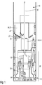
- Fig. 1 shows a shaft drilling system for performing a drilling method according to the invention according to a first embodiment.
- the individual elements of the shaft drilling system and the individual process steps are explained in more detail below.
- a cross section through a shaft end of a vertical drill shaft 10 is shown.
- a central guide string 60 is arranged within the drill shaft 10 along its central long axis.
- a drilling unit 90 is arranged in the shaft end, which is designed to further advance the bore of the drilling shaft 10 and to remove overburden. This takes place, for example, by means of a rotating drill head or with any other suitable mechanized technique for expanding and / or deepening the drill shaft 10.
- the removed overburden collects in the bottom region 12 of the shaft end.
- the drill shaft 10 is watered in the bottom region 12 of the shaft end, so that there is a mixture of overburden and liquid.
- a container 20 is arranged above the drilling unit 90.
- the container 20 is designed as a collecting container 30. It is suitable for taking up the mixture of overburden and liquid from the bottom area 12.
- a conveying container 40 is arranged in the drill shaft 10 between the drilling unit 90 and the collecting container 30. This is preferably designed and / or arranged to surround the central guide strand 60.
- a pump system 50 is also arranged in the shaft end.
- the pump system 50 comprises a pump, a pipe 54 and a feed line 52.
- the pipe 54 extends to the bottom region 12 of the shaft end, in which the mixture of overburden and liquid is located.
- the feed line 52 is connected to the collecting container 30.
- the feed line 52 is guided along a shaft wall.
- the mixture of overburden and liquid is transferred to the collecting container 30 by means of the pump system 50 via the feed line 52. There sedimentation causes at least some of the overburden to settle below in the collecting container 30 and the liquid essentially floats on top.
- An overflow channel 25 is formed all around the collecting container 30 and adjacent to the shaft wall. When the maximum capacity of the collecting container 30 has been reached, excess liquid runs out of the collecting container 30 into the overflow channel 25. From there, the overflowing liquid is again conducted to the bottom region 12 of the shaft end. This is done via a down pipe 22, which is arranged along the shaft wall. Alternatively, for example, the overflowing liquid could run out of the overflow channel 25.
- the collecting container 30 has a flap 35 in its bottom. By opening the flap 35, a ramp is formed between the collection container 30 and the delivery container 40, via which the residual mixture from the collection container 30 reaches the delivery container 40. This takes place during a pause in pumping or when the liquid mixture is pumped into a further container 30 arranged in this area, that is to say when the transfer of overburden by means of liquid to the collecting container 30 has stopped and after the collecting container 30 has been flooded.
- the conveying container 40 is then guided along and preferably through the central guide strand 60 and transported away in the direction of an upper shaft opening. This is done via a pull rope 70.
- the pull rope 70 is preferably also designed to hold the conveying container 40.
- a drilling process that is carried out with the aid of such an arrangement comprises the steps described below.
- a liquid-waste mixture is preferably generated by drilling on the shaft floor.
- the mixture of overburden and liquid is pumped or transferred from the bottom region 12 of the shaft end into the collecting container 30. Pumping takes place until the maximum capacity of the collecting container 30 is reached and beyond.
- the collecting container 30 is flooded by the further pumping. Surplus liquid runs out of the collecting container 30 into the overflow channel 25 and is returned from there back into the bottom region 12 of the shaft end. A residual mixture remains in the collecting container 30.
- the pumping must be interrupted at least temporarily in order to transfer the residual mixture from the collection container 30 into the delivery container 40.
- the parameter or parameters that lead to the interruption of the pumping can be of various types. For example, the time determines how long the pumping takes. Alternatively, the amount of liquid that has already run out of the collecting container 30 by flooding can be recorded. If this has reached a predetermined amount, the pumping process is interrupted. As an alternative or in addition, the weight of the filled collecting container 30 can be determined. For example, a maximum weight is provided.
- the flap 35 in the bottom of the collecting container 30 is opened, so that the residual mixture collected there is reloaded into the conveying container 40.
- the opened flap 35 forms a ramp between the collection container 30 and the delivery container 40.
- the pump line is pivoted over the second collecting container 30 and fills it, while the contents of the first collecting container 30 are reloaded into the delivery container. Pump pauses are avoided and / or reduced and the shaft sinking speed is increased.
- the filled delivery container 40 is transported away in the direction of the upper shaft opening by means of the pull rope 70.
- Fig. 1 shown embodiment of the collecting container 30 and the delivery container 40 are two different units, a new transfer of spoil by means of liquid can already take place when the Delivery container 40 is transported in the direction of the upper shaft opening. This increases the effectiveness of the removal of the overburden or the residual mixture.
- the container 20 is both a collecting container 30 and a conveying container 40.
- the other elements shown essentially correspond to those in FIG Fig. 1 shown and described elements.
- the embodiment of the container 20 in such a way that it is designed both as a collecting container and 30 as a production container 40 means a space saving in the drill shaft 10 and is particularly suitable for drill shafts 10 with smaller diameters, in particular with diameters smaller than four meters (4 m). are.
- a drilling method carried out by means of such an arrangement comprises the following steps: drilling with the following pumping of the overburden / liquid mixture from the bottom of the well 10 into the collecting container 30 or into the conveying container 40 until its maximum capacity is reached and beyond; Returning the liquid that has overflowed into the overflow channel 25 into the bottom region 12 of the shaft end; and interrupting the pumping process during the removal of the container 20 designed as a collecting container 30 and / or a conveying container 40 through the drill shaft 10.
- the container 20 is again arranged in a suitable position in the drill shaft 10, the method can be resumed.
- Fig. 3 shows a top view of an arrangement of a collecting container 30 and a conveying container 40 of the shaft drilling system Fig. 1 ,
- the collecting container 30 is arranged in a lateral region of the drill shaft 10 on the shaft wall.
- An overflow channel 25 is formed in the center of the collecting container 30, through which excess liquid can run off.
- the central guide strand 60 which runs along the central long axis of the drill shaft 10, can also be seen.
- the conveying container 40 is arranged around this central guide line 60.
- the base of the conveyor container 40 is essentially rectangular.
- the conveying container 40 also has a U-shaped recess 26 which extends around the central guide strand 60. The recess 26 extends from a container opening to a container bottom.
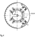
- Fig. 4 shows a plan view of a container 20 of the shaft drilling system arranged in a drilling shaft 10 Fig. 2 ,
- the container 20 is also designed as a collecting container 30 and also as a conveying container 40. It essentially has a round base, which has a U-shaped recess 26.
- the container 30 or 40 is arranged coaxially to the long axis of the drill shaft 10.
- the central guide strand 60 runs within the U-shaped recess 26 of the container 20.
- the center of gravity of the container 30 or 40 is shifted through the U-shaped recess 26, especially when it is filled. This means that the center of gravity of the container 30 or 40 is not on the central long axis of the drill shaft 10, but in the center of gravity of the hoist rope. This makes it easier to pull up the container 30 or 40 on the pull cable 70, which runs offset to the central guide strand 60, and the managers between the container 30 or 40 and the pull cable 70 are minimized.
- Fig. 5 shows how emptying can be carried out on the surface.
- an embodiment of the lifting system 80 is shown, which is arranged on the surface.
- the container 30 or 40 is transported on the pull rope 70 through the drill shaft 10.
- the pull rope 70 is unrolled onto a winch.
- Detachable guide elements / holding elements 72 are arranged on the container 30 or 40, which allow the container 30 or 40 to be tilted for emptying.
- the container 30 or 40 does not have to be detached from the central guide strand 60.
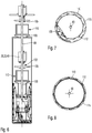
- Fig. 6 is a further advantageous development of the shaft drilling system Fig. 2 shown.
- only one container 20 is provided, which is both a conveying container 40 and a collecting container 30.
- a work platform 100 is arranged below the Container 30 or 40.
- the work platform 100 is connected to the container 30 or 40 by means of struts 102. If the container 30 or 40 moves along the central guide strand 60, the work platform 100 also moves.
- the container 30 or 40 is shown in several positions along the central guide strand 60, as is the work platform 100.
- the work platform 100 is arranged at a distance from the container 30 or 40. In particular, the distance is more than 1.50 m, so that a person can at least bend over on the work platform 100.
- a protective cover 105 is additionally arranged between the work platform 100 and the container 30 or 40, in order to protect people or equipment on the work platform 100.
- a shaft lining 110 can be installed from the work platform 100.
- the working height of the platform 100 is preferably dimensioned such that work can be carried out comfortably and in an upright position by the personnel.
- Fig. 7 shows a top view of a shaft lining 110 within the well shaft 10 before final assembly.
- the shaft lining 110 is pre-assembled plates. The plates run in a spiral over one another and can be expanded to form a cylinder with the diameter of the drill shaft 10.
- the shaft lining 110 can be expanded by means of a suitable tool 108, for example a hydraulic cylinder.
- the shaft lining 110 is pressed against the shaft wall.
- a support structure 115 is located on the shaft wall.
- the support structure 115 serves to hold the shaft lining 110. Butt joints and longitudinal connections are connected to each other to ensure a stable shaft lining.
- Fig. 8 the shaft lining 110 is made Fig. 7 shown after it is fully installed.
- the flexible spacers 112 are in direct contact with the shaft wall. Alternatively or in addition, they can also be in contact with the support structure 115.
Landscapes
- Engineering & Computer Science (AREA)
- Mining & Mineral Resources (AREA)
- Life Sciences & Earth Sciences (AREA)
- Geology (AREA)
- Mechanical Engineering (AREA)
- General Life Sciences & Earth Sciences (AREA)
- Geochemistry & Mineralogy (AREA)
- Physics & Mathematics (AREA)
- Environmental & Geological Engineering (AREA)
- Fluid Mechanics (AREA)
- Earth Drilling (AREA)
Description
- Die vorliegende Erfindung betrifft ein Bohrverfahren mit mittels Flüssigkeit durchgeführter Abraumbeseitigung sowie ein Schachtbohrsystem zur Durchführung eines solchen Bohrverfahrens.
- Bekannte Bohrverfahren umfassen im Allgemeinen die folgenden Schritte. Es wird eine in einem zu bohrenden Bohrschacht an einem Schachtende des Bohrschachts angeordnete Bohreinheit bereitgestellt, die dazu ausgebildet ist, im Wesentlichen durch Bohren Abraum zu erzeugen, indem Gestein und Erdreich abgetragen werden. Beispielsweise erfolgt die Abtragung zusätzlich mittels Sprengung oder mit einer anderen geeigneten Technik zur Erweiterung oder Vertiefung eines Bohrschachts.
- Bei bekannten Verfahren wird der erzeugte Abraum mittels Flüssigkeit, wie Wasser, aufgenommen und das entstehende Gemisch an eine Oberfläche, d. h. in den die Bohrschachtöffnung umgebenden Bereich, befördert. Dies geschieht in der Regel mittels eines Pumpsystems oder eines Lufthebesystems. Vereinzelt wurden auch Kratzsysteme oder Vakuum-Absaugsysteme eingesetzt. Dies hat den Nachteil, dass bei zunehmender Teufe der Bohrschächte das Fördervermögen des Pumpsystems hoch sein muss und darüber hinaus die Gefahr besteht, dass dieses Pumpsystem verstopft. Eine derartige Betriebsstörung kann nur mit großem Aufwand wieder beseitigt werden. Eine solche Störungsbeseitigung ist insbesondere schwierig, wenn aufgrund eines geringen Schachtdurchmessers von 3 m bis 8 m der Schachtzugang erschwert ist. Kratzsysteme sind in abrasiven Gebirgsverhältnissen sehr hohem Verschleiß unterworfen und benötigen zudem zu großen Platzbedarf. Vakuumsysteme haben einen sehr hohen Energiebedarf und erfordern im Schacht eine großvolumige Installation, z. B. Trockenseparation. Es werden hohe Abwärmewerte erzeugt, die wiederum großvolumige Kühlanlagen benötigen. Bei Wasserzufluss sind z. B. Kratz- und Vakuumsysteme uneffektiv.
- An der Oberfläche wird dem Gemisch in der Regel wieder Flüssigkeit entzogen, die dann zurück in das Schachtende geleitet wird, da dort ständig Flüssigkeit benötigt wird, um Abraum abzufördern.
- Meist werden Schächte mit einem geringen Durchmesser von 3 m bis 8 m erweitert, indem der Abraum über eine bereits vorhandene Pilotbohrung und/oder Schächte abgeführt wird, mit allen vorgenannten Nachteilen, Zudem bedeutete die Notwendigkeit einer Pilotbohrung, um überhaupt effizient einen Bohrschacht erweitern zu können, immer zusätzlichen Arbeits-, Zeit- und somit auch Kostenaufwand. Es bedeutet einen großen Aufwand, die Logistik Untertage für den Abraumabtransport zur Verfügung zu stellen.
- Das Abteufen von Schächten im angegebenen Durchmesserbereich ohne eine Pilotbohrung erfolgt meist im konventionellen Sprengbetrieb oder mit Hilfe des sogenannten "Lufthebeverfahrens". Beide Verfahren haben sehr entscheidende Nachteile in puncto Abteufgeschwindigkeit, Projektdauer, Sicherheit und Kosten.
- Beim Lufthebeverfahren ist der gebohrte Schacht während der Bohrarbeiten verfahrensbedingt vollständig bis zum Schachtkragen mit Flüssigkeit gefüllt. Die Abteufgeschwindigkeiten sind besonders in harten Formationen sehr niedrig und die Richtungsgenauigkeit ist eingeschränkt. Der Flüssigkeitssäule müssen in schwierigen, brüchigen Formationen Additive hinzugefügt werden, um ein unkontrolliertes Abfließen der Flüssigkeit in die umgebende Gebirgsformation zu verhindern. Dies ist oft sehr zeitaufwendig, teuer und nur unzureichend zu kontrollieren. Die Schachtwandauskleidung kann erst nachträglich eingebracht werden.
- Alternativ werden Schächte auch im Sprengverfahren abgeteuft. Die entsprechenden Nachteile sind hinlänglich bekannt. So verringert sich mit zunehmender Schachttiefe die Abteufgeschwindigkeit. Durch Bildung von Sprengrissen kann es zu einer Beeinträchtigung der umgebenden geologischen Formationen kommen und es besteht ein erhöhtes Sicherheitsrisiko für Personal am Schachtboden.
- Die
DE 36 09 111 A1 offenbart ein Bohrverfahren gemäß dem Oberbegriff des Anspruchs 1. Auch unter Berücksichtigung der sich weiter verschärfenden internationalen Sicherheitsbestimmungen besteht daher besonders im Bergbau Bedarf nach einem effizienteren, sicheren Bohrverfahren und einem Schachtbohrsystem, welches effizienter eingesetzt werden kann. Diese Aufgabe wird bezüglich des Bohrverfahrens mit den Merkmalen des Anspruch 1 und bezüglich des Schachtbohrsystems mit den Merkmalen des Anspruchs 10 gelöst. Vorteilhafte Ausgestaltungen sind jeweils Gegenstand der abhängigen Ansprüche. - Erfindungsgemäß wird bei einem Bohrverfahren eine Bohreinheit an einem Schachtende eines Bohrschachts angeordnet. Der Bohrschacht weist beispielsweise einen Mindestdurchmesser von 3 m bis 8 m, bevorzugt 5 m auf.
- Erfindungsgemäß wird Abraum mittels der Bohreinheit durch bohrenden Abtrag erzeugt. Optional kann zusätzlich mittels Sprengungen Abraum erzeugt werden.
- Erfindungsgemäß wird innerhalb des Bohrschachts ein Behälter für den Abraum bereitgestellt, insbesondere ist dieser zur Aufnahme eines Gemischs aus Abraum und Flüssigkeit geeignet. Erfindungsgemäß wird der Abraum mittels Flüssigkeit in den Behälter transferiert, so dass sich in diesem ein Gemisch aus Abraum und Flüssigkeit ansammelt. Dazu ist ein Transfersystem, beispielweise ein Pumpsystem vorgesehen.
- Sowohl die Bohreinheit als auch der Behälter sind innerhalb des Bohrschachts angeordnet. Als eine Anordnung innerhalb des Bohrschachtes wird eine Anordnung verstanden, bei der sich der Behälter dauerhaft oder wenigstens während der Dauer des Befüllvorgangs in dem durch das Hohlvolumen des Schachtes befindlichen Volumen befindet. Bevorzugt ist der Behälter näher zum Schachtende angeordnet als zur Bohrschachtöffnung. Beispielsweise beträgt der Abstand zwischen Bohreinheit und Behälter weniger als 10 m. Durch diese Anordnung wird die notwendige Pumpkapazität stark reduziert.
- Bevorzugt wird der Abraum, der sich nach dem Abtragen durch die Bohreinheit in einem Bodenbereich des Schachtendes anlagert, gewässert, so dass dort das Gemisch aus Abraum und Wasser als Flüssigkeit entsteht. Beispielsweise wird das Gemisch aus Abraum und Flüssigkeit aus dem Schachtende (von der Schachtsohle) in den Behälter gepumpt.
- Erfindungsgemäß erfolgt ein Fluten des Behälters mit dem Gemisch, wobei wenigstens überstehende Flüssigkeit aus dem Behälter überläuft. Bevorzugt wird die übergelaufene Flüssigkeit durch eine in oder an dem Behälter angeordnete Überlaufrinne beziehungsweise einen Überlauf aufgenommen. Das Fluten erfolgt durch weiteren Transfer von Abraum mittels mit Abraum beladener Flüssigkeit in den Behälter. Innerhalb des Behälters setzt sich der schwerere Abraum zumindest teilweise unten ab und die Flüssigkeit schwimmt oben auf. Groberer Abraum sinkt im Behälter schneller ab als zum Beispiel feinkörniger Abraum. Durch das Fluten des Behälters, also durch das Füllen über die maximale Füllhöhe, auch als maximales Fassungsvermögen bezeichnet, hinaus wird überstehende Flüssigkeit aus dem Behälter verdrängt und weiterer Abraum setzt sich im Behälter ab. Dadurch verringert sich der Flüssigkeitsanteil in dem Restgemisch, das im Behälter verbleibt. Es wird durch Sedimentation der Abraumanteil im Behälter erhöht, während der Flüssigkeitsanteil im Behälter verringert wird. Da ferner der Abraum keine homogene Zusammensetzung aufweist, sondern meist grobere und feinere Bestandteile aufweist, bildet die lose Schüttung größerer Bestandteile des Abraums Zwischenräume aus, in denen kleinere Bestandteile des Abraums sich einlagern können, so dass insgesamt ferner ein dichteres Gemisch erreicht wird, indem sich die feineren Bestandteile zwischen den gröberen Bestandteilen in dem Behälter anhäufen können.
- Das Absetzen des Abraums erfordert eine gewisse Zeit, diese ist durch die Dauer des Befüllvorgangs gegeben. Es lässt sich sagen, dass je länger der Befüllvorgang dauert, desto dichter kann das Gemisch werden, da mehr Zeit gegeben ist, in der sich Abraum absetzen kann. Die Dauer des Befüllvorgangs wird durch die Transfergeschwindigkeit und durch das maximale Fassungsvermögen des Behälters bestimmt. Idealerweise sind diese beiden Größen aufeinander abgestimmt, um einen guten Kompromiss aus Effektivität des Bohrvorgangs und der Beschaffenheit des Gemischs zu erhalten.
- Erfindungsgemäß erfolgt während des Bohrverfahrens eine Rückführung der überstehenden beziehungsweise der übergelaufenen Flüssigkeit ins Schachtende (zur Schachtsohle), insbesondere in den Bodenbereich, um dort weiter anfallenden Abraum zu wässern.
- Erfindungsgemäß umfasst das Bohrverfahren zudem den Schritt des Abtransports des Restgemischs durch den Bohrschacht.
- Es ist ein herausragender Vorteil der Erfindung, dass auch mit Feinanteilen beladene Flüssigkeit in den Hohlräumen des groben Abraums im Behälter von der Schachtsohle abtransportiert wird. Dadurch wird eine zunehmende Verschlammung der Flüssigkeit am Schachtboden vermieden, die sonst die Pumpbarkeit des Flüssigkeitsgemisches mindestens erheblich beeinträchtigen könnte. Die Erfindung kommt ohne die Bereitstellung der üblichen großvolumigen Separationselemente aus, was wiederum in entscheidende Platzvorteile am Schachboden bei kleineren Schachtdurchmessern resultiert. Der Flüssigkeitsspiegel an der Schachtsohle kann durch Zuführen von sauberer/separierter Flüssigkeit durch einen hohlen Führungsstrang kontrolliert werden. Ohne diesen Vorteil bliebe das effiziente und sichere maschinelle Bohren von Blindschächten mit kleineren Durchmessern weiterhin ungelöst.
- In einer vorteilhaften Ausführungsform des Bohrverfahrens wird zunächst die überstehende Flüssigkeit von einer in oder an dem Behälter angeordneten Überlaufrinne aufgenommen, bevor sie zurückgeführt wird. Beispielsweise ist die Überlaufrinne umlaufend am Rand des Behälters ausgebildet.
- In einer weiteren vorteilhaften Ausführungsform des Bohrverfahrens erfolgt die Rückführung der übergelaufenen Flüssigkeit über ein Fallrohr. Beispielsweise verläuft das Fallrohr entlang einer Schachtwandung, insbesondere von einer Befüllplattform am oberen Ende der Bohreinheit innen entlang einer maschinenbedingten Schachtwandstützvorrichtung. Insbesondere mündet eine gegebenenfalls vorhandene Überlaufrinne in das Fallrohr.
- In einer weiteren Ausführungsform des Bohrverfahrens erfolgt ein Umladen des Restgemischs (des von der Schachtsohle verpumpten Flüssigkeitsgemischs) aus dem Behälter in einen separaten (zusätzlichen) Förderbehälter, der ebenfalls in dem Bohrschacht angeordnet ist. Der Behälter erfüllt dann die Funktion eines Sammelbehälters, insbesondere eines stationären Sammelbehälters. In dem Sammelbehälter wird zunächst durch Überlauf und Rückführung überschüssiger Flüssigkeit ein Restgemisch mit hohem Abraumanteil erzeugt. Das Umladen erfolgt beispielsweise dadurch, dass der Sammelbehälter oberhalb des Förderbehälters angeordnet ist und sich durch Öffnen einer Klappe im Boden des Sammelbehälters eine Rampe ausbildet. Über diese Rampe wird das Restgemisch von dem Sammelbehälter in den Förderbehälter befördert.
- Eine weitere Ausführungsform des Bohrverfahrens umfasst das Abladen des Gemisches beziehungsweise das Entleeren des Förderbehälters außerhalb des Bohrschachts sowie das Rücktransportieren des Förderbehälters in den Bohrschacht insbesondere in eine Ladeposition zur Wiederaufnahme der einzelnen Verfahrensschritte.
- Diese Ausführungsform ermöglicht es, dass weiterer Abraum mittels Flüssigkeit in den Sammelbehälter transferiert werden kann, während der Förderbehälter das Restgemisch abtransportiert. Die Effektivität des Abtransports des Restgemischs und somit auch die Schachtabteufgeschwindigkeit werden so erheblich gesteigert.
- Während der gesamten vorgenannten Verfahrensschritte besteht die Möglichkeit, dass die Bohreinheit weiteren Abraum abträgt und ein Vortrieb des Bohrschachts unabhängig von dem Förderzyklus des Behälters vorangetrieben wird. Alternativ kann die Abtragung des Abraums während aller oder auch nur während einzelner Verfahrensschritte pausieren, beispielsweise um anderes in dem Schachtende angeordnetes Equipment zu schützen.
- In einer weiteren vorteilhaften Ausgestaltung der Erfindung ist der Behälter selber der durch den Bohrschacht abtransportierbare Förderbehälter. Alternativ kann es sich bei dem Förderbehälter auch um ein weiteres (zusätzliches) Element handeln, wie vorstehend im Zusammenhang mit dem als stationären Sammelbehälter ausgebildeten Behälter beschrieben wurde.
- Wie bereits weiter oben beschrieben wurde, umfasst das erfindungsgemäße Verfahren den Schritt des Abtransports des Restgemischs durch den Bohrschacht. Insbesondere erfolgt der Abtransport des Restgemischs hierbei in dem Förderbehälter.
- In einer weiteren vorteilhaften Ausgestaltung der Erfindung umfasst das Verfahren weiter den Schritt des Entleerens des Förderbehälters außerhalb des Bohrschachts. Dies erfolgt beispielsweise in einen Sammelbunker, in welchem sich der Abraum des Gemischs weiter absetzen kann. Obenauf schwimmende Flüssigkeit kann dann ebenfalls wieder, nach erfolgter Aufbereitung, zur Schachtsohle zurückgeführt werden. Weitere Maßnahmen zur Entwässerung des Gemischs, beispielsweise Siebverfahren, sind denkbar.
- In einer noch weiteren vorteilhaften Ausgestaltung der Erfindung umfasst das Verfahren zudem den Schritt des Rückführens des geleerten Förderbehälters in den Bohrschacht.
- Das Abtransportieren des Restgemischs kann beispielsweise über ein Zugseil und ein Hubsystem erfolgen. Das Hubsystem ist außerhalb des Bohrschachts angeordnet und umfasst eine Seilwinde, an der das Zugseil aufgerollt wird, wodurch der Förderbehälter durch den Bohrschacht transportiert wird. Anders ausgestaltete Hubsysteme sind ebenfalls denkbar und im Sinne der Erfindung mit umfasst. Ein Hubsystem im Sinne der Erfindung ist dazu geeignet, das Gemisch, auch als Restgemisch bezeichnet, durch den Bohrschacht, insbesondere in dem Förderbehälter, zu transportieren. Zudem ist das Hubsystem bevorzugt auch dazu geeignet, den Förderbehälter in den Bohrschacht zurückzuführen.
- Bevorzugt ist der Förderbehälter eine zentrale lange Achse des Bohrschachts umgebend angeordnet. Insbesondere in Bohrschächten mit einem eher geringen Durchmesser kleiner als vier Meter (< 4 m) und einem entsprechend beschränkten Platzangebot innerhalb des Bohrschachts eignet sich diese Anordnung. So wird das Risiko eines Kontakts von Behälter und Schachtwandung minimiert und vermieden. Die Volumenkapazität des Behälters wird maximiert.
- Insbesondere kann der Behälter derart ausgebildet und angeordnet sein, dass sein Schwerpunkt, insbesondere im leeren Zustand und zusätzlich auch im gefüllten Zustand bei homogener Befüllung, nicht auf der zentralen langen Achse des Bohrschachts liegt. Durch seinen außerhalb der Schachtachse befindlichen Schwerpunkt werden die Führungskräfte zum Transport des Behälters minimiert.
- Bevorzugt verläuft entlang der zentralen langen Achse des Bohrschachts ein zentraler Führungsstrang und/oder Hebestrang, der wenigstens zum Heben der Bohreinheit und beispielsweise ferner als tragende Befestigung für diejenigen Einrichtungen dient, die zur Versorgung des im Bohrschacht angeordneten Equipments vorgesehen sind, wie elektrische Leitungen und/oder Flüssigkeitszuleitungen und/oder Flüssigkeitsableitungen. Die Zuleitungen etc. werden vorzugsweise durch am Führungsstrang befestigte Abdeckungen geschützt. Diese Abdeckungen sind vorzugsweise so ausgebildet, dass diese während der Fördervorgänge gleichzeitig als Führungsschienen für den Behälter dienen.
- Der Behälter weist bevorzugt eine Aussparung auf, die derart ausgebildet ist, dass der zentrale Führungsstrang darin verlaufen kann. Beispielsweise weist der Behälter eine in Längsrichtung des Behälters sich von der Behälteröffnung zum Behälterboden erstreckende Aussparung auf. Insbesondere ist die Aussparung im Querschnitt U-förmig ausgebildet.
- In einem Bohrschacht ergibt sich durch die Aussparung eine effektiv raumfüllende Anordnung des Behälters um den zentralen Führungsstrang. Ferner sorgt das Vorsehen der Aussparung für eine Verlagerung des Schwerpunkts gegenüber dem nicht ausgesparten Behälter. Dadurch wird erreicht, dass der Behälter längs des Führungsstrangs an einem Zugsystem, wie Zugseil, sich selbst stabilisierend befördert werden kann. Die Führungskräfte werden dadurch minimiert und sehr vorteilhafte höhere Fördergeschwindigkeiten sind erreichbar. Das heißt, dass der Schwerpunkt des Förderbehälters, insbesondere in einem leeren Zustand und auch im gefüllten Zustand bei homogener Befüllung, nicht auf der zentralen langen Achse des Bohrschachts liegt, was das Hochziehen an einem Zugseil, das versetzt zum zentralen Führungsstrang verläuft, erleichtert und entsprechend höhere Fördergeschwindigkeiten ermöglicht; entsprechend wird auch die Schachtabteufgeschwindigkeit erhöht.
- Auch das Entleeren des Förderbehälters durch Verkippung relativ zu dem zentralen Führungsstrang wird durch die Aussparung ermöglicht, ohne dass der Förderbehälter komplett vom Führungsstrang gelöst werden muss. Bevorzugt sind Halteelemente an dem Förderbehälter angeordnet, an denen der Förderbehälter gelenkig und damit um eine Schwenkachse verkippbar befestigt ist.
- Das erfindungsgemäße Bohrverfahren eignet sich insbesondere zur Anwendung in einem im Wesentlichen lotrecht ausgebildeten Bohrschacht.
- Gemäß einer vorteilhaften Ausführungsform des Behälters, in den das Gemisch aus Flüssigkeit und Abraum gepumpt wird, weist die obere Querschnittsöffnung des Behälters ein Gitter auf. Bevorzugt ist das Gitter unterhalb des Überlaufs angeordnet. Das Gitter dient als Grobfilter und hindert das grobere Bohrgut entsprechend der Maschenweite daran, wieder aus dem Behälter zu gelangen. Die Maschenweite kann bevorzugt entsprechend den Bohrgutbeschaffenheiten verändert werden. Für die Zuführung des Gemischs aus Flüssigkeit und Abraum ist in dem Gitter eine entsprechende Öffnung vorgesehen. Die Öffnung kann alternative auch dadurch ausgebildet sein, dass das Gitter nicht die gesamte Querschnittsöffnung des Behälters überdeckt. Dieser Grobfilter reinigt sich, sobald die Zufuhr des Gemischs unterbrochen beziehungsweise gestoppt wird.
- Gemäß einer bevorzugten Ausgestaltung ist das Gitter so ausgestaltet, dass zumindest einzelne Gitterrippen verlängert ausgestaltet sind und in den Behälter hinein ragen. Dadurch wird das durch den Einfüllvorgang turbulente Flüssigkeitsgemisch zusätzlich beruhigt und der Prozess des Absetzens des Abraums wird beschleunigt.
- In einer noch weiteren vorteilhaften Ausgestaltung der Erfindung ist innerhalb des Bohrschachts mindestens eine Arbeitsplattform vorgesehen. Von der Arbeitsplattform aus kann Personal Arbeiten innerhalb des Bohrschachts verrichten und muss nicht in den gefluteten Bodenbereich des Bohrschachts. Bevorzugt ist die Arbeitsplattform den zentralen Führungsstrang umgebend innerhalb des Bohrschachts angeordnet. Auf diese Weise kann eine maximale Größe der Arbeitsplattform mit entsprechend optimiertem Arbeitsplatzangebot erreicht werden. Die Versorgung des Personals mit ausreichend Atemluft, wird durch entsprechende Zuführung durch den freien Innenquerschnitt des Führungsstrangs gewährleistet.
- Gemäß einer weiteren vorteilhaften Ausgestaltung ist die Plattform beweglich entlang des zentralen Führungsstrangs angeordnet. Insbesondere ist sie unterhalb des den zentralen Führungsstrang umgebenden Behälters angeordnet. Besonders bevorzugt wird sie von dem Behälter gehalten. Beispielsweise ist die Arbeitsplattform über Streben mit dem Behälter verbunden. Aus Platzgründen ist es von Vorteil, wenn der Behälter sowohl Förder- als auch Sammelbehälter ist. Die Arbeitsplattform kann aber auch in der zweiteiligen Ausführungsform des Behälters unterhalb des Förderbehälters angeordnet werden. Wird der Behälter entlang des zentralen Führungsstrangs bewegt, bewegt sich die Arbeitsplattform ebenfalls.
- In einer weiteren Ausgestaltung ist die Arbeitsplattform dazu ausgebildet, weiteres Equipment innerhalb des Bohrschachts zu transportieren und zu halten. Beispielsweise ist an einer Unterseite der Arbeitsplattform eine weitere Bohreinheit angeordnet. Insbesondere ist die Arbeitsplattform daher dazu geeignet, von dort aus eine Schachtauskleidung an der Schachtwandung zu installieren. Beispielsweise handelt es ich bei der Schachtauskleidung um vormontierte Platten (sogenannte liner-plates), die zu einer zylindrischen Röhre aufgeweitet werden können. Die vormontierten Platten werden von der Oberfläche aus um den zentralen Führungsstrang herum auf der Arbeitsplattform in den Bohrschacht transportiert. Dort wird die Schachtauskleidung mittels geeignetem Werkzeug aufgeweitet und an die Schachtwandung gedrückt. Dieses System kann auch automatisiert sein ohne die Notwendigkeit von Personal im Bohrschacht. Die Anwendung von an der Oberfläche vormontierten Schachtwandstützplatten und deren mögliche automatisierte Installation sind nur bei dem beschriebenen Bohrsystem möglich, da außerhalb des zentralen Führungsstranges keine weiteren störenden Zuleitungen jeglicher Art angebracht sind.
- Bevorzugt ist zwischen der Arbeitsplattform und dem Behälter eine Schutzabdeckung angeordnet, um Personen und Equipment zu schützen, die sich auf der Arbeitsplattform befinden.
- Aufgrund der vorteilhaften Nutzung des Platzangebots innerhalb des Bohrschachts zur Anordnung von Förder- und Sammelbehälter und der bereits im Bohrschacht erfolgenden teilweisen Entwässerung des Gemischs aus Abraum und Flüssigkeit eignet sich das beschriebene Bohrverfahren in besonderer Weise für das Abteufen von Schächten ohne die Notwendigkeit eines bereits vorhandenen Holraumes als Ziel Untertage. Ein solches Bohrverfahren kann man auch als Vollschachtbohren oder Blindschachtbohren bezeichnen.
- Das beschriebene Schachtbohrsystem ermöglicht ein innovatives Bohrverfahren, mit dem besonders kleinere Vollschachtbohrungen bzw. Blindschachtbohrungen zwischen ca. 3 m und 8 m Durchmesser effizienter, schneller und für das Personal sicher niedergebracht werden können. Das System präsentiert im Vergleich zu allen bisherigen Systemen eine einfache Separation und Förderung des Bohrguts. Gleichzeitig erlaubt die besondere Anordnung von Bohrmaschine bzw. Bohreinheit, der Bohrgutseparation und der im Schacht zentral geführten Bohrgutabförderung einen effektiven Schachtwandausbau unmittelbar oberhalb der Bohrmaschine/der Bohreinheit. Die Schachtwandung ist bis zur Stabilisierung durch entsprechenden Ausbau permanent aktiv gestützt. Die besondere Anordnung der innovativen Baugruppen präsentiert selbst bei den kleineren Bohrdurchmessern genügend Freiraum, um temporär Bohrgerät im Schacht oberhalb der Bohrmaschine zu installieren, um Sondierbohrungen bzw. Ankern und Konsolidierarbeiten durchzuführen. Die Bohrmaschine ist vorzugsweise über einen segmentierten Führungsstrang mit dem Hubwerk am Schachtkragen verbunden und kann somit bei Bedarf ohne vorherige Demontage zum Schachtkragen gezogen werden, z. B. bei möglichen Wassereinbrüchen, anderen Notfällen und zwecks Demontage nach Vollendung des Schachtes. Die entsprechende Verbindung dient auch als Führung für den Förderkorb und als Leitung und Träger von Versorgungsleitungen. Über den offenen Innenquerschnitt des Führungsstranges kann bei Bedarf der Bereich der Bohrmaschine am Schachtboden sowohl mit Wasser als auch Luft versorgt werden. Nur die besondere Anordnung der Maschinenelemente erlaubt es, bei den kleineren Schachtdurchmessern einen vorgefertigten Schachtwandausbau direkt oberhalb der Bohrmaschine zu installieren, da der Schachtquerschnitt außerhalb des Führungsstrangs komplett freigehalten werden kann (d. h. keine Versorgungsleitungen etc.).
- Die Erfindung wird anhand der nachfolgenden Figuren näher erläutert. Die Figuren sind nur beispielhaft zu verstehen und stellen lediglich bevorzugte Ausführungsvarianten dar, die im Folgenden unter Bezugnahme auf die Zeichnung näher erläutert werden und die die Erfindung nicht beschränken sollen. Die Erfindung ist nicht auf die beschriebenen Ausführungsbeispiele beschränkt, sie kann auch weitere Ausführungsvarianten umfassen, die sich die Erfindung zu Nutze machen. In der Zeichnung zeigen schematisch:
- Fig. 1
- eine Teilansicht im Längsschnitt eines Ausführungsbeispiels eines Schachtbohrsystems gemäß der Erfindung innerhalb eines Bohrschachts zur Durchführung eines Ausführungsbeispiels eines erfindungsgemäßen Bohrverfahrens,
- Fig. 2
- eine Teilansicht im Längsschnitt eines weiteren Ausführungsbeispiels eines Schachtbohrsystems gemäß der Erfindung innerhalb eines Bohrschachts zur Durchführung eines weiteren Ausführungsbeispiels eines erfindungsgemäßen Bohrverfahrens,
- Fig. 3
- eine Draufsicht auf eine Anordnung eines Sammelbehälters und eines Förderbehälters des Schachtbohrsystems aus
Fig. 1 , - Fig. 4
- eine Draufsicht auf eine Anordnung eines Sammelbehälters und eines Förderbehälters des Schachtbohrsystems aus
Fig. 2 , - Fig. 5
- eine Teilansicht des Schachtbohrsystems aus
Fig. 2 an einer Oberfläche außerhalb des Bohrschachts, - Fig. 6
- eine Teilansicht im Längsschnitt eines noch weiteren Ausführungsbeispiels eines Schachtbohrsystems gemäß der Erfindung innerhalb eines Bohrschachts zur Durchführung eines weiteren Ausführungsbeispiels eines erfindungsgemäßen Bohrverfahrens,
- Fig. 7
- eine Draufsicht auf eine Schachtauskleidung für einen Bohrschacht vor der Installation am Bohrschacht und
- Fig. 8
- eine Draufsicht auf die Schachtauskleidung aus
Fig. 7 nach ihrer Installation am Bohrschacht. - In den unterschiedlichen Figuren sind hinsichtlich ihrer Funktion gleichwertige Teile stets mit denselben Bezugszeichen versehen, so dass diese in der Regel auch nur einmal beschrieben werden.
-
Fig. 1 zeigt ein Schachtbohrsystem zur Durchführung eines erfindungsgemäßen Bohrverfahrens gemäß einem ersten Ausführungsbeispiel. Nachfolgend sind die einzelnen Elemente des Schachtbohrsystems und die einzelnen Verfahrensschritte näher erläutert. - Gezeigt ist ein Querschnitt durch ein Schachtende eines lotrechten Bohrschachts 10. Innerhalb des Bohrschachts 10 ist entlang seiner zentralen langen Achse ein zentraler Führungsstrang 60 angeordnet.
- Weiter ist im Schachtende eine Bohreinheit 90 angeordnet, die dazu ausgebildet ist, die Bohrung des Bohrschachts 10 weiter voranzutreiben und Abraum abzutragen. Dies erfolgt beispielsweise mittels eines rotierenden Bohrkopfes oder mit jeder anderen geeigneten mechanisierten Technik zur Erweiterung und/oder Vertiefung des Bohrschachts 10. Im Bodenbereich 12 des Schachtendes sammelt sich der abgetragene Abraum. Der Bohrschacht 10 ist im Bodenbereich 12 des Schachtendes gewässert, so dass sich dort ein Gemisch aus Abraum und Flüssigkeit befindet.
- Ein Behälter 20 ist oberhalb der Bohreinheit 90 angeordnet. Im gezeigten Ausführungsbeispiel ist der Behälter 20 als Sammelbehälter 30 ausgebildet. Er ist dazu geeignet, das Gemisch aus Abraum und Flüssigkeit vom Bodenbereich 12 aufzunehmen.
- Zwischen der Bohreinheit 90 und dem Sammelbehälter 30 ist ein Förderbehälter 40 in dem Bohrschacht 10 angeordnet. Dieser ist bevorzugt den zentralen Führungsstrang 60 umgebend ausgestaltet und/oder angeordnet.
- Ebenfalls im Schachtende angeordnet ist ein Pumpsystem 50. Das Pumpsystem 50 umfasst eine Pumpe, ein Rohr 54 und eine Zuleitung 52. Das Rohr 54 erstreckt sich zum Bodenbereich 12 des Schachtendes, in dem sich das Gemisch aus Abraum und Flüssigkeit befindet. Die Zuleitung 52 steht mit dem Sammelbehälter 30 in Verbindung. Beispielsweise ist die Zuleitung 52 entlang einer Schachtwandung geführt. Das Gemisch aus Abraum und Flüssigkeit wird mittels des Pumpsystems 50 über die Zuleitung 52 in den Sammelbehälter 30 transferiert. Dort setzt sich durch Sedimentation wenigstens ein Teil des Abraums unten im Sammelbehälter 30 ab und die Flüssigkeit schwimmt im Wesentlichen obenauf.
- Umlaufend um den Sammelbehälter 30 und angrenzend an die Schachtwandung ist eine Überlaufrinne 25 ausgebildet. Wenn das maximale Fassungsvermögen des Sammelbehälters 30 erreicht ist, läuft überstehende Flüssigkeit aus dem Sammelbehälter 30 in die Überlaufrinne 25. Von dort wird die überlaufende Flüssigkeit wieder zu dem Bodenbereich 12 des Schachtendes geleitet. Dies erfolgt über ein Fallrohr 22, das entlang der Schachtwandung angeordnet ist. Alternativ könnte beispielsweise die überlaufende Flüssigkeit aus der Überlaufrinne 25 herauslaufen.
- Der Sammelbehälter 30 weist eine Klappe 35 in seinem Boden auf. Durch Öffnen der Klappe 35 bildet sich zwischen dem Sammelbehälter 30 und dem Förderbehälter 40 eine Rampe aus, über die das Restgemisch aus dem Sammelbehälter 30 in den Förderbehälter 40 gelangt. Dies erfolgt während einer Pumppause oder wenn das Flüssigkeitsgemisch in einen weiteren in diesem Bereich angeordneten Behälter 30 gepumpt wird, also wenn der Transfer von Abraum mittels Flüssigkeit in den Sammelbehälter 30 ruht und nachdem der Sammelbehälter 30 geflutet wurde.
- Der Förderbehälter 40 wird im Anschluss entlang des zentralen Führungsstrangs 60 und bevorzugt durch diesen geführt und in Richtung einer oberen Schachtöffnung abtransportiert. Dies erfolgt über ein Zugseil 70. Bevorzugt ist das Zugseil 70 zudem dazu ausgebildet, den Förderbehälter 40 zu halten.
- Ein Bohrverfahren, das mit Hilfe einer solchen Anordnung durchgeführt wird, umfasst die im Folgenden beschriebenen Schritte.
- Vorzugsweise wird durch Bohren am Schachtboden ein Flüssigkeits-Abraumgemisch erzeugt. Das Gemisch aus Abraum und Flüssigkeit wird vom Bodenbereich 12 des Schachtendes in den Sammelbehälter 30 gepumpt bzw. transferiert. Das Pumpen erfolgt, bis das maximale Fassungsvermögen des Sammelbehälters 30 erreicht ist und darüber hinaus. Der Sammelbehälter 30 wird durch das weitere Pumpen geflutet. Überstehende Flüssigkeit läuft aus dem Sammelbehälter 30 heraus in die Überlaufrinne 25 und wird von dort wieder in den Bodenbereich 12 des Schachtendes zurückgeführt. In dem Sammelbehälter 30 verbleibt ein Restgemisch.
- Ist nur ein Sammelbehälter 30 vorhanden, muss das Pumpen zumindest zeitweise unterbrochen werden, um das Restgemisch von dem Sammelbehälter 30 in den Förderbehälter 40 umzuladen. Der oder die Parameter, die zur Unterbrechung des Pumpens führen, können verschiedener Art sein. Beispielsweise wird über die Zeit festgelegt, wie lange gepumpt wird. Alternativ kann die Flüssigkeitsmenge erfasst werden, die bereits durch Fluten aus dem Sammelbehälter 30 heraus gelaufen ist. Hat diese eine vorgegebene Menge erreicht, wird der Pumpvorgang unterbrochen. Alternativ oder ergänzend kann das Gewicht des gefüllten Sammelbehälters 30 ermittelt werden. Beispielsweise ist ein maximales Gewicht vorgesehen.
- Während der Pumppause wird die Klappe 35 im Boden des Sammelbehälters 30 geöffnet, so dass das dort gesammelte Restgemisch in den Förderbehälter 40 umgeladen wird. Die geöffnete Klappe 35 bildet dabei eine Rampe zwischen dem Sammelbehälter 30 und dem Förderbehälter 40 aus.
- Sind mindestens zwei Sammelbehälter 30 angeordnet, wird die Pumpleitung über den zweiten Sammelbehälter 30 geschwenkt und befüllt diesen, während der Inhalt des ersten Sammelbehälters 30 in den Förderbehälter umgeladen wird. Dadurch werden Pumppausen vermieden und/oder reduziert und die Schachtabteufgeschwindigkeit gesteigert.
- Als weiterer Verfahrensschritt wird der gefüllte Förderbehälter 40 mittels des Zugseils 70 in Richtung der oberen Schachtöffnung abtransportiert.
- Wenn wie im in
Fig. 1 gezeigten Ausführungsbeispiel der Sammelbehälter 30 und der Förderbehälter 40 zwei verschiedene Einheiten sind, kann ein erneuter Transfer von Abraum mittels Flüssigkeit bereits dann erfolgen, wenn der Förderbehälter 40 in Richtung der oberen Schachtöffnung transportiert wird. Dadurch wird die Effektivität des Abtransports des Abraums beziehungsweise des Restgemischs gesteigert. - In dem in
Fig. 2 gezeigten Ausführungsbeispiel ist der Behälter 20 sowohl Sammelbehälter 30 als auch Förderbehälter 40. Die anderen gezeigten Elemente entsprechen im Wesentlichen den inFig. 1 gezeigten und beschriebenen Elementen. Die Ausführungsform des Behälters 20 derart, dass er zugleich als Sammelbehälter und 30 als Förderbehälter 40 ausgebildet ist, bedeutet ein Platzersparnis im Bohrschacht 10 und eignet sich insbesondere für Bohrschächte 10 mit kleineren Durchmessern, insbesondere mit Durchmessern, die kleiner als vier Meter (4 m) sind. Wie beschrieben, ist es möglich und vorteilhaft, bei größeren Schachtdurchmessern einen oder mehrere Sammelbehälter 30 (als Abraumzwischenlager) anzuordnen, die bei dem dem Durchmesser entsprechenden höheren Abraumanfall einen kontinuierlicheren Bohrzyklus erlauben mit entsprechend höheren Abteufraten. - Ein mittels einer solchen Anordnung durchgeführtes Bohrverfahren umfasst folgende Schritte: Bohren mit folgendem Pumpen des Abraum-/Flüssigkeitsgemischs vom Grund des Bohrschachts 10 in den Sammelbehälter 30 bzw. in den Förderbehälter 40, bis dessen maximales Fassungsvermögen erreicht ist und darüber hinaus; Rückführen der in die Überlaufrinne 25 übergelaufenen Flüssigkeit in den Bodenbereich 12 des Schachtendes; und Unterbrechen des Pumpvorgangs während des Abtransports des als Sammelbehälter 30 und/oder Förderbehälter 40 ausgebildeten Behälters 20 durch den Bohrschacht 10. Wenn der Behälter 20 wieder in geeigneter Position in dem Bohrschacht 10 angeordnet ist, kann das Verfahren wieder aufgenommen werden.
-
Fig. 3 zeigt eine Draufsicht auf eine Anordnung eines Sammelbehälters 30 und eines Förderbehälters 40 des Schachtbohrsystems ausFig. 1 . Der Sammelbehälter 30 ist in einem seitlichen Bereich des Bohrschachts 10 an der Schachtwandung angeordnet. Mittig in dem Sammelbehälter 30 ist eine Überlaufrinne 25 ausgebildet, über die überstehende Flüssigkeit ablaufen kann. Weiter zu sehen ist der zentrale Führungsstrang 60, der entlang der zentralen langen Achse des Bohrschachts 10 verläuft. Um diesen zentralen Führungsstrang 60 ist der Förderbehälter 40 angeordnet. Im gezeigten Ausführungsbeispiel ist die Grundfläche des Förderbehälters 40 im Wesentlichen rechteckig ausgebildet. Der Förderbehälter 40 weist zudem eine U-förmige Aussparung 26 auf, die um den zentralen Führungsstrang 60 verläuft. Die Aussparung 26 erstreckt sich von einer Behälteröffnung zu einem Behälterboden. -
Fig. 4 zeigt eine Draufsicht auf einen in einem Bohrschacht 10 angeordneten Behälter 20 des Schachtbohrsystems ausFig. 2 . Der Behälter 20 ist zugleich als Sammelbehälter 30 und auch als Förderbehälter 40 ausgebildet. Er hat im Wesentlichen eine runde Grundfläche, die eine U-förmige Aussparung 26 aufweist. Der Behälter 30 bzw. 40 ist koaxial zu der langen Achse des Bohrschachts 10 angeordnet. Der zentrale Führungsstrang 60 verläuft innerhalb der U-förmigen Aussparung 26 des Behälters 20. - Durch die U-förmige Aussparung 26 verlagert sich der Schwerpunkt des Behälters 30 bzw. 40, insbesondere wenn dieser gefüllt ist, aus der zentralen Lage. Das heißt, dass der Schwerpunkt des Behälters 30 bzw. 40 nicht auf der zentralen langen Achse des Bohrschachts 10 liegt, sondern im Zugschwerpunkt des Förderseils. Dadurch wird das Hochziehen des Behälters 30 bzw. 40 an dem Zugseil 70, das versetzt zum zentralen Führungsstrang 60 verläuft, erleichtert und die Führungskräfte zwischen Behälter 30 bzw. 40 und Zugseil 70 werden minimiert.
- Auch das Entleeren des Behälters 30 bzw. 40 durch Verkippung relativ zu der langen Achse des Bohrschachts 10 wird durch die U-förmige Aussparung 26 ermöglicht.
- In
Fig. 5 ist gezeigt, wie die Entleerung an der Oberfläche erfolgen kann. Zudem ist ein Ausführungsbeispiel des Hubsystems 80 gezeigt, das an der Oberfläche angeordnet ist. Der Behälter 30 bzw. 40 wird an dem Zugseil 70 durch den Bohrschacht 10 transportiert. Dazu wird das Zugseil 70 auf eine Winde aufbeziehungsweise abgerollt. An dem Behälter 30 bzw. 40 sind lösbare Führungselemente/Haltelemente 72 angeordnet, die ein Verkippen des Behälters 30 bzw. 40 zur Entleerung erlauben. Der Behälter 30 bzw. 40 muss dabei nicht von dem zentralen Führungsstrang 60 gelöst werden. - In
Fig. 6 ist eine weitere vorteilhafte Weiterbildung des Schachtbohrsystems ausFig. 2 gezeigt. Zum Abtransport des Abraums ist nur ein Behälter 20 vorgesehen, der zugleich Förderbehälter 40 als auch Sammelbehälter 30 ist. Unterhalb des Behälters 30 bzw. 40 ist eine Arbeitsplattform 100 angeordnet. Die Arbeitsplattform 100 ist mittels Streben 102 mit dem Behälter 30 bzw. 40 verbunden. Bewegt sich der Behälter 30 bzw. 40 entlang des zentralen Führungsstrangs 60, bewegt sich die Arbeitsplattform 100 ebenfalls. Der Behälter 30 bzw. 40 ist in mehreren Positionen entlang des zentralen Führungsstrangs 60 gezeigt, ebenso die Arbeitsplattform 100. Die Arbeitsplattform 100 ist beabstandet von dem Behälter 30 bzw. 40 angeordnet. Insbesondere ist der Abstand mehr als 1,50 m, sodass eine Person zumindest gebückt auf der Arbeitsplattform 100 stehen kann. Zwischen der Arbeitsplattform 100 und dem Behälter 30 bzw. 40 ist zusätzlich noch eine Schutzabdeckung 105 angeordnet, um Personen oder Equipment auf der Arbeitsplattform 100 zu schützen. Von der Arbeitsplattform 100 aus kann eine Schachtauskleidung 110 installiert werden. Die Arbeitshöhe der Plattform 100 ist bevorzugt so dimensioniert, dass anfallende Arbeiten vom Personal komfortabel und in aufrechter Haltung durchgeführt werden können. -
Fig. 7 zeigt eine Draufsicht auf eine Schachtauskleidung 110 innerhalb des Bohrschachts 10 vor der endgültigen Montage. Bei der Schachtauskleidung 110 handelt es sich um vormontierte Platten. Die Platten laufen spiralförmig übereinander und können zu einem Zylinder mit dem Durchmesser des Bohrschachts 10 aufgeweitet werden. An der Außenseite der Röhre bzw. Schachtauskleidung 110 befinden sich flexible Abstandshalter 112, die auch bei den anfallenden Schachtdurchmessertoleranzen einen sicheren Kontakt zur Schachtwand gewährleisten. Die Schachtauskleidung 110 ist mittels geeignetem Werkzeug 108, beispielsweise einem hydraulischen Zylinder, aufweitbar. Die Schachtauskleidung 110 wird an die Schachtwandung gedrückt. An der Schachtwandung befindet sich eine Stützstruktur 115. Die Stützstruktur 115 dient dazu, die Schachtauskleidung 110 zu halten. Stöße und Längsverbindungen werden miteinander verbunden, um eine stabile Schachtauskleidung zu gewährleisten. - In
Fig. 8 ist die Schachtauskleidung 110 ausFig. 7 gezeigt, nachdem sie vollständig installiert ist. Die flexiblen Abstandshalter 112 stehen dabei in direktem Kontakt mit der Schachtwandung. Alternativ oder ergänzend können sie auch in Kontakt mit der Stützstruktur 115 stehen.
Claims (22)
- Bohrverfahren umfassend folgende Schritte:- Anordnen einer Bohreinheit (90) an einem Schachtende eines Bohrschachts (10);- Erzeugen von Abraum mittels der Bohreinheit (90);- Bereitstellen eines Behälters (30, 40) für den Abraum innerhalb des Bohrschachts (10);- Transferieren des Abraums in den Behälter (30, 40) mittels Flüssigkeit, so dass sich in dem Behälter (30, 40) ein Gemisch aus Abraum und Flüssigkeit befindet;
gekennzeichnet durch- Fluten des Behälters (30, 40) durch weiteres Transferieren von Abraum mittels Flüssigkeit, wobei wenigstens überstehende Flüssigkeit überläuft und ein Restgemisch mit hohem Abraumanteil im Behälter (30, 40) verbleibt;- Rückführen der übergelaufenen Flüssigkeit ins Schachtende;- Abtransportieren des Restgemischs durch den Bohrschacht (10). - Bohrverfahren gemäß dem vorhergehenden Anspruch, weiter umfassend den Schritt:- Auffangen der überlaufenden Flüssigkeit in einer Überlaufrinne (25), insbesondere in einer in oder an dem Behälter (30, 40) angeordneten Überlaufrinne (25).
- Bohrverfahren gemäß einem der vorhergehenden Ansprüche, wobei das Rückführen der übergelaufenen Flüssigkeit durch ein Fallrohr (22) erfolgt.
- Bohrverfahren gemäß einem der vorhergehenden Ansprüche, wobei der Behälter (30) ein stationärer Sammelbehälter (30) ist und weiter umfassend folgenden Schritt:- Umladen des Restgemischs aus dem Behälter (30) in einen zusätzlichen, im Bohrschacht (10) angeordneten und durch diesen abtransportierbaren Förderbehälter (40).
- Bohrverfahren gemäß einem der vorhergehenden Ansprüche 1 bis 3, wobei der Behälter (40) ein durch den Bohrschacht (10) abtransportierbarer Förderbehälter (40) ist.
- Bohrverfahren gemäß einem der beiden vorhergehenden Ansprüche, wobei das Abtransportieren des Restgemischs in dem Förderbehälter (40) erfolgt.
- Bohrverfahren gemäß einem der drei vorhergehenden Ansprüche, weiter umfassend den Schritt:- Entleeren des Förderbehälters (40) außerhalb des Bohrschachts (10).
- Bohrverfahren gemäß dem vorhergehenden Anspruch, weiter umfassend den Schritt:- Rückführen des geleerten Förderbehälters (40) in den Bohrschacht (10).
- Bohrverfahren gemäß einem der vorhergehenden Ansprüche, wobei das Abtransportieren des Restgemischs mittels eines Zugseils (70) erfolgt.
- Schachtbohrsystem, umfassend- eine Bohreinheit (90) zur Anordnung in einem Bohrschacht (10), die dazu ausgebildet ist, Abraum an einem Schachtende des Bohrschachts (10) abzutragen,- einen Behälter (30, 40), der in dem Bohrschacht (10) angeordnet ist und der dazu geeignet ist, ein Gemisch aus Abraum und Flüssigkeit aufzunehmen,
gekennzeichnet durch- ein Transfersystem, beispielsweise ein Pumpsystem (50), zum Transferieren des Abraums mittels Flüssigkeit in den Behälter (30, 40), wobei der Behälter (30, 40) geflutet wird und in dem Behälter (30, 40) ein Restgemisch verbleibt,- ein Hubsystem (80), das dazu geeignet ist, das Restgemisch durch den Bohrschacht (10) zu transportieren. - Schachtbohrsystem gemäß dem vorhergehenden Anspruch, dadurch gekennzeichnet, dass der Behälter (30, 40) eine Überlaufrinne (25) umfasst.
- Schachtbohrsystem gemäß dem vorhergehenden Anspruch, dadurch gekennzeichnet, dass die Überlaufrinne (25) in ein Fallrohr (22) mündet.
- Schachtbohrsystem gemäß dem vorhergehenden Anspruch, dadurch gekennzeichnet, dass das Fallrohr (22) entlang einer Schachtwandung geführt ist.
- Schachtbohrsystem gemäß einem der vorhergehenden Ansprüche 10 bis 13, dadurch gekennzeichnet, dass ein zentraler Führungs- und/oder Hebestrang (60), wenigstens zum Heben der Bohreinheit (90), entlang einer zentralen langen Achse des Bohrschachts (10) verläuft.
- Schachtbohrsystem gemäß einem der vorhergehenden Ansprüche 10 bis 14, dadurch gekennzeichnet, dass der Behälter (40) angeordnet ist, eine zentrale lange Achse des Bohrschachts (10) zu umgeben.
- Schachtbohrsystem gemäß dem vorhergehenden Anspruch, dadurch gekennzeichnet, dass der Behälter (40) derart ausgebildet und angeordnet ist, dass sein Schwerpunkt, insbesondere im leeren Zustand des Behälters (40), nicht auf der zentralen langen Achse des Bohrschachts (10) liegt.
- Schachtbohrsystem gemäß einem der vorhergehenden zwei Ansprüche, dadurch gekennzeichnet, dass der Behälter (40) eine Aussparung (26), bevorzugt eine im Querschnitt U-förmige Aussparung (26), aufweist, die sich von einer Behälteröffnung zu einem Behälterboden erstreckt.
- Schachtbohrsystem gemäß einem der vorhergehenden Ansprüche 10 bis 17, dadurch gekennzeichnet, dass der Behälter (40) Teil des Hubsystems (80) ist und durch den Bohrschacht (10) abtransportierbar ist, so dass er als Förderbehälter und als Sammelbehälter dient.
- Schachtbohrsystem gemäß einem der vorhergehenden Ansprüche 10 bis 18, dadurch gekennzeichnet, dass der Behälter (40) am zentralen Führungsstrang (60) befestigt und/oder geführt ist.
- Schachtbohrsystem gemäß einem der vorhergehenden Ansprüche 10 bis 19, dadurch gekennzeichnet, dass der Behälter (30) ein stationärer Sammelbehälter (30) ist und in dem Bohrschacht (10) ein zusätzlicher Förderbehälter (40) angeordnet ist.
- Schachtbohrsystem gemäß dem vorhergehenden Anspruch, dadurch gekennzeichnet, dass der Sammelbehälter (30) oberhalb des zusätzlichen Förderbehälters (40) anordenbar ist.
- Schachtbohrsystem gemäß einem der beiden vorhergehenden Ansprüche, dadurch gekennzeichnet, dass der Sammelbehälter (30) eine Klappe (35) im Boden aufweist.
Applications Claiming Priority (3)
| Application Number | Priority Date | Filing Date | Title |
|---|---|---|---|
| DE102016106020 | 2016-04-01 | ||
| DE102016011332 | 2016-09-21 | ||
| PCT/EP2017/057502 WO2017167856A1 (de) | 2016-04-01 | 2017-03-30 | Bohrverfahren und schachtbohrsystem |
Publications (2)
| Publication Number | Publication Date |
|---|---|
| EP3436664A1 EP3436664A1 (de) | 2019-02-06 |
| EP3436664B1 true EP3436664B1 (de) | 2020-02-12 |
Family
ID=58579140
Family Applications (1)
| Application Number | Title | Priority Date | Filing Date |
|---|---|---|---|
| EP17718486.8A Active EP3436664B1 (de) | 2016-04-01 | 2017-03-30 | Bohrverfahren und schachtbohrsystem |
Country Status (5)
| Country | Link |
|---|---|
| EP (1) | EP3436664B1 (de) |
| CN (1) | CN109072696B (de) |
| AU (1) | AU2017242643B2 (de) |
| WO (1) | WO2017167856A1 (de) |
| ZA (1) | ZA201805981B (de) |
Family Cites Families (10)
| Publication number | Priority date | Publication date | Assignee | Title |
|---|---|---|---|---|
| US3265138A (en) * | 1963-08-19 | 1966-08-09 | George E Failing Company | Magazine for storing and handling drill pipe in rotary drilling rig |
| US3735825A (en) * | 1972-03-07 | 1973-05-29 | Dresser Ind | Pressure equalizing system for rock bits |
| US3901330A (en) * | 1973-11-21 | 1975-08-26 | Brown Oil Tools | Electric power drive assembly |
| DE3516312C1 (de) * | 1985-05-07 | 1986-10-16 | Gesellschaft für Strahlen- und Umweltforschung mbH München, 8042 Oberschleißheim | Bohrmaschine mit einem ueber ein verlaengertes Bohrgestaenge antreibbaren Bohrkopf |
| DE3609111A1 (de) * | 1986-03-19 | 1987-10-01 | Turmag Turbo Masch Ag | Bohrmaschine |
| CN2046921U (zh) * | 1989-04-17 | 1989-11-01 | 辽河石油勘探局钻井二公司科技科 | 旋流钻进增速器 |
| KR100208546B1 (ko) * | 1994-08-25 | 1999-07-15 | 야마오까 유지 | 세로 구멍용 굴착기 |
| DE19702533A1 (de) * | 1997-01-24 | 1998-07-30 | Bauer Spezialtiefbau | Bohrvorrichtung und Drehmomentstütze für eine Bohrvorrichtung |
| DE10310726B3 (de) * | 2003-03-12 | 2004-09-30 | Bauer Spezialtiefbau Gmbh | Kernbohrvorrichtung mit Spülung |
| DE102012025395A1 (de) * | 2012-12-24 | 2014-06-26 | Herrenknecht Ag | Vorrichtung zum Abteufen eines Schachts |
-
2017
- 2017-03-30 CN CN201780021431.8A patent/CN109072696B/zh not_active Expired - Fee Related
- 2017-03-30 WO PCT/EP2017/057502 patent/WO2017167856A1/de not_active Ceased
- 2017-03-30 EP EP17718486.8A patent/EP3436664B1/de active Active
- 2017-03-30 AU AU2017242643A patent/AU2017242643B2/en not_active Ceased
-
2018
- 2018-09-06 ZA ZA2018/05981A patent/ZA201805981B/en unknown
Non-Patent Citations (1)
| Title |
|---|
| None * |
Also Published As
| Publication number | Publication date |
|---|---|
| CN109072696A (zh) | 2018-12-21 |
| WO2017167856A1 (de) | 2017-10-05 |
| AU2017242643B2 (en) | 2020-01-23 |
| EP3436664A1 (de) | 2019-02-06 |
| ZA201805981B (en) | 2019-06-26 |
| AU2017242643A1 (en) | 2018-10-18 |
| CN109072696B (zh) | 2020-09-25 |
Similar Documents
| Publication | Publication Date | Title |
|---|---|---|
| DE69113034T2 (de) | Gerät und verfahren zum kontinuierlichen abbau. | |
| EP2739790B1 (de) | Abtrennen eines pfahles off shore | |
| DE10046497C2 (de) | Gewinnungseinrichtung für untertägige Erzgewinnungsbetriebe sowie Verfahren zum Hereingewinnen von Gewinnungsprodukten in untertägigen Erzgewinnungsbetrieben | |
| DE202010017762U1 (de) | Ausbilden eines Schachts für eine unterirdische Mine | |
| EP1978204B1 (de) | Erdbohrgerät | |
| DE2728853A1 (de) | Verfahren und vorrichtung zum abbauen von mineralien in hohlraeumen einer unterirdischen lagerstaette | |
| DE112014003885T5 (de) | Skip und Kreuzkopf | |
| DE102014011878B4 (de) | Bodenfräsmaschine, Verfahren zum Ausbau und Verfahren zum Einbau einer Fräseinrichtung | |
| DE2256054C2 (de) | Abraum-Saugbaggereinrichtung mit wenigstens einem Saugschlauch zum Abführen des Abraumschlammes | |
| DE112014002718T5 (de) | Führungssystem | |
| DE69124364T2 (de) | Vorschubfahrzeug für ein kontinuierlich arbeitendes abbaugerät | |
| EP3330441B1 (de) | Unterwasserabbauvorrichtung und verfahren zum abbau | |
| EP0819819B1 (de) | Fräskopf, Bohrvorrichtung sowie Vorrichtung und Verfahren zum Meeresbodenbohren | |
| WO2021069154A1 (de) | Unterwasser-abtragsvorrichtung und verfahren zum abtragen von bodenmaterial unter wasser | |
| DE102018009987B4 (de) | BODENFRÄSMASCHlNE | |
| EP3436664A1 (de) | Bohrverfahren und schachtbohrsystem | |
| DE3729561C2 (de) | ||
| DE4121394C2 (de) | ||
| EP4392646A1 (de) | Schachtbagger | |
| EP3564446B1 (de) | Unterwasserabbauvorrichtung und verfahren zum abbau | |
| EP2666911B1 (de) | Verfahren zum Herstellen einer Bodenmörtelwand im Boden | |
| DE112014001994T5 (de) | Verfahren zum Bewegen einer Komponente oder eines Materials auf ein und innerhalb eines Niveaus eines Schachtabteufsystems | |
| DE2548249C2 (de) | Vorrichtung zur hydraulischen Abförderung von trocken abgebautem und vorgebrochenem Material | |
| DE2548252A1 (de) | Verfahren und vorrichtung zum abbau von kohlehaltigem material | |
| DE102007009037A1 (de) | Horizontalfilterbrunnen |
Legal Events
| Date | Code | Title | Description |
|---|---|---|---|
| STAA | Information on the status of an ep patent application or granted ep patent |
Free format text: STATUS: UNKNOWN |
|
| STAA | Information on the status of an ep patent application or granted ep patent |
Free format text: STATUS: THE INTERNATIONAL PUBLICATION HAS BEEN MADE |
|
| PUAI | Public reference made under article 153(3) epc to a published international application that has entered the european phase |
Free format text: ORIGINAL CODE: 0009012 |
|
| STAA | Information on the status of an ep patent application or granted ep patent |
Free format text: STATUS: REQUEST FOR EXAMINATION WAS MADE |
|
| 17P | Request for examination filed |
Effective date: 20180830 |
|
| AK | Designated contracting states |
Kind code of ref document: A1 Designated state(s): AL AT BE BG CH CY CZ DE DK EE ES FI FR GB GR HR HU IE IS IT LI LT LU LV MC MK MT NL NO PL PT RO RS SE SI SK SM TR |
|
| AX | Request for extension of the european patent |
Extension state: BA ME |
|
| DAV | Request for validation of the european patent (deleted) | ||
| DAX | Request for extension of the european patent (deleted) | ||
| GRAP | Despatch of communication of intention to grant a patent |
Free format text: ORIGINAL CODE: EPIDOSNIGR1 |
|
| STAA | Information on the status of an ep patent application or granted ep patent |
Free format text: STATUS: GRANT OF PATENT IS INTENDED |
|
| INTG | Intention to grant announced |
Effective date: 20191022 |
|
| GRAS | Grant fee paid |
Free format text: ORIGINAL CODE: EPIDOSNIGR3 |
|
| GRAA | (expected) grant |
Free format text: ORIGINAL CODE: 0009210 |
|
| STAA | Information on the status of an ep patent application or granted ep patent |
Free format text: STATUS: THE PATENT HAS BEEN GRANTED |
|
| AK | Designated contracting states |
Kind code of ref document: B1 Designated state(s): AL AT BE BG CH CY CZ DE DK EE ES FI FR GB GR HR HU IE IS IT LI LT LU LV MC MK MT NL NO PL PT RO RS SE SI SK SM TR |
|
| REG | Reference to a national code |
Ref country code: GB Ref legal event code: FG4D Free format text: NOT ENGLISH |
|
| REG | Reference to a national code |
Ref country code: CH Ref legal event code: EP |
|
| REG | Reference to a national code |
Ref country code: AT Ref legal event code: REF Ref document number: 1232352 Country of ref document: AT Kind code of ref document: T Effective date: 20200215 |
|
| REG | Reference to a national code |
Ref country code: IE Ref legal event code: FG4D Free format text: LANGUAGE OF EP DOCUMENT: GERMAN |
|
| REG | Reference to a national code |
Ref country code: DE Ref legal event code: R096 Ref document number: 502017003796 Country of ref document: DE |
|
| PG25 | Lapsed in a contracting state [announced via postgrant information from national office to epo] |
Ref country code: NO Free format text: LAPSE BECAUSE OF FAILURE TO SUBMIT A TRANSLATION OF THE DESCRIPTION OR TO PAY THE FEE WITHIN THE PRESCRIBED TIME-LIMIT Effective date: 20200512 Ref country code: RS Free format text: LAPSE BECAUSE OF FAILURE TO SUBMIT A TRANSLATION OF THE DESCRIPTION OR TO PAY THE FEE WITHIN THE PRESCRIBED TIME-LIMIT Effective date: 20200212 Ref country code: FI Free format text: LAPSE BECAUSE OF FAILURE TO SUBMIT A TRANSLATION OF THE DESCRIPTION OR TO PAY THE FEE WITHIN THE PRESCRIBED TIME-LIMIT Effective date: 20200212 |
|
| REG | Reference to a national code |
Ref country code: LT Ref legal event code: MG4D |
|
| REG | Reference to a national code |
Ref country code: NL Ref legal event code: MP Effective date: 20200212 |
|
| PG25 | Lapsed in a contracting state [announced via postgrant information from national office to epo] |
Ref country code: BG Free format text: LAPSE BECAUSE OF FAILURE TO SUBMIT A TRANSLATION OF THE DESCRIPTION OR TO PAY THE FEE WITHIN THE PRESCRIBED TIME-LIMIT Effective date: 20200512 Ref country code: IS Free format text: LAPSE BECAUSE OF FAILURE TO SUBMIT A TRANSLATION OF THE DESCRIPTION OR TO PAY THE FEE WITHIN THE PRESCRIBED TIME-LIMIT Effective date: 20200612 Ref country code: GR Free format text: LAPSE BECAUSE OF FAILURE TO SUBMIT A TRANSLATION OF THE DESCRIPTION OR TO PAY THE FEE WITHIN THE PRESCRIBED TIME-LIMIT Effective date: 20200513 Ref country code: SE Free format text: LAPSE BECAUSE OF FAILURE TO SUBMIT A TRANSLATION OF THE DESCRIPTION OR TO PAY THE FEE WITHIN THE PRESCRIBED TIME-LIMIT Effective date: 20200212 Ref country code: LV Free format text: LAPSE BECAUSE OF FAILURE TO SUBMIT A TRANSLATION OF THE DESCRIPTION OR TO PAY THE FEE WITHIN THE PRESCRIBED TIME-LIMIT Effective date: 20200212 Ref country code: HR Free format text: LAPSE BECAUSE OF FAILURE TO SUBMIT A TRANSLATION OF THE DESCRIPTION OR TO PAY THE FEE WITHIN THE PRESCRIBED TIME-LIMIT Effective date: 20200212 |
|
| PG25 | Lapsed in a contracting state [announced via postgrant information from national office to epo] |
Ref country code: NL Free format text: LAPSE BECAUSE OF FAILURE TO SUBMIT A TRANSLATION OF THE DESCRIPTION OR TO PAY THE FEE WITHIN THE PRESCRIBED TIME-LIMIT Effective date: 20200212 |
|
| PG25 | Lapsed in a contracting state [announced via postgrant information from national office to epo] |
Ref country code: ES Free format text: LAPSE BECAUSE OF FAILURE TO SUBMIT A TRANSLATION OF THE DESCRIPTION OR TO PAY THE FEE WITHIN THE PRESCRIBED TIME-LIMIT Effective date: 20200212 Ref country code: DK Free format text: LAPSE BECAUSE OF FAILURE TO SUBMIT A TRANSLATION OF THE DESCRIPTION OR TO PAY THE FEE WITHIN THE PRESCRIBED TIME-LIMIT Effective date: 20200212 Ref country code: PT Free format text: LAPSE BECAUSE OF FAILURE TO SUBMIT A TRANSLATION OF THE DESCRIPTION OR TO PAY THE FEE WITHIN THE PRESCRIBED TIME-LIMIT Effective date: 20200705 Ref country code: SK Free format text: LAPSE BECAUSE OF FAILURE TO SUBMIT A TRANSLATION OF THE DESCRIPTION OR TO PAY THE FEE WITHIN THE PRESCRIBED TIME-LIMIT Effective date: 20200212 Ref country code: SM Free format text: LAPSE BECAUSE OF FAILURE TO SUBMIT A TRANSLATION OF THE DESCRIPTION OR TO PAY THE FEE WITHIN THE PRESCRIBED TIME-LIMIT Effective date: 20200212 Ref country code: LT Free format text: LAPSE BECAUSE OF FAILURE TO SUBMIT A TRANSLATION OF THE DESCRIPTION OR TO PAY THE FEE WITHIN THE PRESCRIBED TIME-LIMIT Effective date: 20200212 Ref country code: EE Free format text: LAPSE BECAUSE OF FAILURE TO SUBMIT A TRANSLATION OF THE DESCRIPTION OR TO PAY THE FEE WITHIN THE PRESCRIBED TIME-LIMIT Effective date: 20200212 Ref country code: CZ Free format text: LAPSE BECAUSE OF FAILURE TO SUBMIT A TRANSLATION OF THE DESCRIPTION OR TO PAY THE FEE WITHIN THE PRESCRIBED TIME-LIMIT Effective date: 20200212 Ref country code: RO Free format text: LAPSE BECAUSE OF FAILURE TO SUBMIT A TRANSLATION OF THE DESCRIPTION OR TO PAY THE FEE WITHIN THE PRESCRIBED TIME-LIMIT Effective date: 20200212 |
|
| REG | Reference to a national code |
Ref country code: DE Ref legal event code: R097 Ref document number: 502017003796 Country of ref document: DE |
|
| PG25 | Lapsed in a contracting state [announced via postgrant information from national office to epo] |
Ref country code: MC Free format text: LAPSE BECAUSE OF FAILURE TO SUBMIT A TRANSLATION OF THE DESCRIPTION OR TO PAY THE FEE WITHIN THE PRESCRIBED TIME-LIMIT Effective date: 20200212 |
|
| PLBE | No opposition filed within time limit |
Free format text: ORIGINAL CODE: 0009261 |
|
| STAA | Information on the status of an ep patent application or granted ep patent |
Free format text: STATUS: NO OPPOSITION FILED WITHIN TIME LIMIT |
|
| REG | Reference to a national code |
Ref country code: BE Ref legal event code: MM Effective date: 20200331 |
|
| PG25 | Lapsed in a contracting state [announced via postgrant information from national office to epo] |
Ref country code: LU Free format text: LAPSE BECAUSE OF NON-PAYMENT OF DUE FEES Effective date: 20200330 |
|
| 26N | No opposition filed |
Effective date: 20201113 |
|
| PG25 | Lapsed in a contracting state [announced via postgrant information from national office to epo] |
Ref country code: IT Free format text: LAPSE BECAUSE OF FAILURE TO SUBMIT A TRANSLATION OF THE DESCRIPTION OR TO PAY THE FEE WITHIN THE PRESCRIBED TIME-LIMIT Effective date: 20200212 Ref country code: IE Free format text: LAPSE BECAUSE OF NON-PAYMENT OF DUE FEES Effective date: 20200330 |
|
| PG25 | Lapsed in a contracting state [announced via postgrant information from national office to epo] |
Ref country code: PL Free format text: LAPSE BECAUSE OF FAILURE TO SUBMIT A TRANSLATION OF THE DESCRIPTION OR TO PAY THE FEE WITHIN THE PRESCRIBED TIME-LIMIT Effective date: 20200212 Ref country code: SI Free format text: LAPSE BECAUSE OF FAILURE TO SUBMIT A TRANSLATION OF THE DESCRIPTION OR TO PAY THE FEE WITHIN THE PRESCRIBED TIME-LIMIT Effective date: 20200212 Ref country code: BE Free format text: LAPSE BECAUSE OF NON-PAYMENT OF DUE FEES Effective date: 20200331 |
|
| PGFP | Annual fee paid to national office [announced via postgrant information from national office to epo] |
Ref country code: FR Payment date: 20210322 Year of fee payment: 5 Ref country code: CH Payment date: 20210324 Year of fee payment: 5 |
|
| PGFP | Annual fee paid to national office [announced via postgrant information from national office to epo] |
Ref country code: GB Payment date: 20210324 Year of fee payment: 5 Ref country code: DE Payment date: 20210323 Year of fee payment: 5 |
|
| PG25 | Lapsed in a contracting state [announced via postgrant information from national office to epo] |
Ref country code: TR Free format text: LAPSE BECAUSE OF FAILURE TO SUBMIT A TRANSLATION OF THE DESCRIPTION OR TO PAY THE FEE WITHIN THE PRESCRIBED TIME-LIMIT Effective date: 20200212 Ref country code: MT Free format text: LAPSE BECAUSE OF FAILURE TO SUBMIT A TRANSLATION OF THE DESCRIPTION OR TO PAY THE FEE WITHIN THE PRESCRIBED TIME-LIMIT Effective date: 20200212 Ref country code: CY Free format text: LAPSE BECAUSE OF FAILURE TO SUBMIT A TRANSLATION OF THE DESCRIPTION OR TO PAY THE FEE WITHIN THE PRESCRIBED TIME-LIMIT Effective date: 20200212 |
|
| PG25 | Lapsed in a contracting state [announced via postgrant information from national office to epo] |
Ref country code: MK Free format text: LAPSE BECAUSE OF FAILURE TO SUBMIT A TRANSLATION OF THE DESCRIPTION OR TO PAY THE FEE WITHIN THE PRESCRIBED TIME-LIMIT Effective date: 20200212 Ref country code: AL Free format text: LAPSE BECAUSE OF FAILURE TO SUBMIT A TRANSLATION OF THE DESCRIPTION OR TO PAY THE FEE WITHIN THE PRESCRIBED TIME-LIMIT Effective date: 20200212 |
|
| REG | Reference to a national code |
Ref country code: DE Ref legal event code: R119 Ref document number: 502017003796 Country of ref document: DE |
|
| REG | Reference to a national code |
Ref country code: CH Ref legal event code: PL |
|
| GBPC | Gb: european patent ceased through non-payment of renewal fee |
Effective date: 20220330 |
|
| PG25 | Lapsed in a contracting state [announced via postgrant information from national office to epo] |
Ref country code: LI Free format text: LAPSE BECAUSE OF NON-PAYMENT OF DUE FEES Effective date: 20220331 Ref country code: GB Free format text: LAPSE BECAUSE OF NON-PAYMENT OF DUE FEES Effective date: 20220330 Ref country code: FR Free format text: LAPSE BECAUSE OF NON-PAYMENT OF DUE FEES Effective date: 20220331 Ref country code: DE Free format text: LAPSE BECAUSE OF NON-PAYMENT OF DUE FEES Effective date: 20221001 Ref country code: CH Free format text: LAPSE BECAUSE OF NON-PAYMENT OF DUE FEES Effective date: 20220331 |
|
| REG | Reference to a national code |
Ref country code: AT Ref legal event code: MM01 Ref document number: 1232352 Country of ref document: AT Kind code of ref document: T Effective date: 20220330 |
|
| PG25 | Lapsed in a contracting state [announced via postgrant information from national office to epo] |
Ref country code: AT Free format text: LAPSE BECAUSE OF NON-PAYMENT OF DUE FEES Effective date: 20220330 |