EP3436832B1 - Dispositif de transport - Google Patents
Dispositif de transport Download PDFInfo
- Publication number
- EP3436832B1 EP3436832B1 EP17714403.7A EP17714403A EP3436832B1 EP 3436832 B1 EP3436832 B1 EP 3436832B1 EP 17714403 A EP17714403 A EP 17714403A EP 3436832 B1 EP3436832 B1 EP 3436832B1
- Authority
- EP
- European Patent Office
- Prior art keywords
- laboratory vessel
- laboratory
- region
- conveying unit
- conveying
- Prior art date
- Legal status (The legal status is an assumption and is not a legal conclusion. Google has not performed a legal analysis and makes no representation as to the accuracy of the status listed.)
- Active
Links
Images


Classifications
-
- G—PHYSICS
- G01—MEASURING; TESTING
- G01N—INVESTIGATING OR ANALYSING MATERIALS BY DETERMINING THEIR CHEMICAL OR PHYSICAL PROPERTIES
- G01N35/00—Automatic analysis not limited to methods or materials provided for in any single one of groups G01N1/00 - G01N33/00; Handling materials therefor
- G01N35/00029—Automatic analysis not limited to methods or materials provided for in any single one of groups G01N1/00 - G01N33/00; Handling materials therefor provided with flat sample substrates, e.g. slides
-
- C—CHEMISTRY; METALLURGY
- C12—BIOCHEMISTRY; BEER; SPIRITS; WINE; VINEGAR; MICROBIOLOGY; ENZYMOLOGY; MUTATION OR GENETIC ENGINEERING
- C12M—APPARATUS FOR ENZYMOLOGY OR MICROBIOLOGY; APPARATUS FOR CULTURING MICROORGANISMS FOR PRODUCING BIOMASS, FOR GROWING CELLS OR FOR OBTAINING FERMENTATION OR METABOLIC PRODUCTS, i.e. BIOREACTORS OR FERMENTERS
- C12M23/00—Constructional details, e.g. recesses, hinges
- C12M23/02—Form or structure of the vessel
- C12M23/10—Petri dish
-
- C—CHEMISTRY; METALLURGY
- C12—BIOCHEMISTRY; BEER; SPIRITS; WINE; VINEGAR; MICROBIOLOGY; ENZYMOLOGY; MUTATION OR GENETIC ENGINEERING
- C12M—APPARATUS FOR ENZYMOLOGY OR MICROBIOLOGY; APPARATUS FOR CULTURING MICROORGANISMS FOR PRODUCING BIOMASS, FOR GROWING CELLS OR FOR OBTAINING FERMENTATION OR METABOLIC PRODUCTS, i.e. BIOREACTORS OR FERMENTERS
- C12M23/00—Constructional details, e.g. recesses, hinges
- C12M23/50—Means for positioning or orientating the apparatus
-
- G—PHYSICS
- G01—MEASURING; TESTING
- G01N—INVESTIGATING OR ANALYSING MATERIALS BY DETERMINING THEIR CHEMICAL OR PHYSICAL PROPERTIES
- G01N35/00—Automatic analysis not limited to methods or materials provided for in any single one of groups G01N1/00 - G01N33/00; Handling materials therefor
- G01N35/00584—Control arrangements for automatic analysers
- G01N35/00722—Communications; Identification
- G01N35/00732—Identification of carriers, materials or components in automatic analysers
-
- C—CHEMISTRY; METALLURGY
- C12—BIOCHEMISTRY; BEER; SPIRITS; WINE; VINEGAR; MICROBIOLOGY; ENZYMOLOGY; MUTATION OR GENETIC ENGINEERING
- C12M—APPARATUS FOR ENZYMOLOGY OR MICROBIOLOGY; APPARATUS FOR CULTURING MICROORGANISMS FOR PRODUCING BIOMASS, FOR GROWING CELLS OR FOR OBTAINING FERMENTATION OR METABOLIC PRODUCTS, i.e. BIOREACTORS OR FERMENTERS
- C12M23/00—Constructional details, e.g. recesses, hinges
- C12M23/48—Holding appliances; Racks; Supports
-
- C—CHEMISTRY; METALLURGY
- C12—BIOCHEMISTRY; BEER; SPIRITS; WINE; VINEGAR; MICROBIOLOGY; ENZYMOLOGY; MUTATION OR GENETIC ENGINEERING
- C12M—APPARATUS FOR ENZYMOLOGY OR MICROBIOLOGY; APPARATUS FOR CULTURING MICROORGANISMS FOR PRODUCING BIOMASS, FOR GROWING CELLS OR FOR OBTAINING FERMENTATION OR METABOLIC PRODUCTS, i.e. BIOREACTORS OR FERMENTERS
- C12M33/00—Means for introduction, transport, positioning, extraction, harvesting, peeling or sampling of biological material in or from the apparatus
-
- C—CHEMISTRY; METALLURGY
- C12—BIOCHEMISTRY; BEER; SPIRITS; WINE; VINEGAR; MICROBIOLOGY; ENZYMOLOGY; MUTATION OR GENETIC ENGINEERING
- C12M—APPARATUS FOR ENZYMOLOGY OR MICROBIOLOGY; APPARATUS FOR CULTURING MICROORGANISMS FOR PRODUCING BIOMASS, FOR GROWING CELLS OR FOR OBTAINING FERMENTATION OR METABOLIC PRODUCTS, i.e. BIOREACTORS OR FERMENTERS
- C12M41/00—Means for regulation, monitoring, measurement or control, e.g. flow regulation
- C12M41/48—Automatic or computerized control
-
- G—PHYSICS
- G01—MEASURING; TESTING
- G01N—INVESTIGATING OR ANALYSING MATERIALS BY DETERMINING THEIR CHEMICAL OR PHYSICAL PROPERTIES
- G01N35/00—Automatic analysis not limited to methods or materials provided for in any single one of groups G01N1/00 - G01N33/00; Handling materials therefor
- G01N35/00029—Automatic analysis not limited to methods or materials provided for in any single one of groups G01N1/00 - G01N33/00; Handling materials therefor provided with flat sample substrates, e.g. slides
- G01N2035/00039—Transport arrangements specific to flat sample substrates, e.g. pusher blade
-
- G—PHYSICS
- G01—MEASURING; TESTING
- G01N—INVESTIGATING OR ANALYSING MATERIALS BY DETERMINING THEIR CHEMICAL OR PHYSICAL PROPERTIES
- G01N35/00—Automatic analysis not limited to methods or materials provided for in any single one of groups G01N1/00 - G01N33/00; Handling materials therefor
- G01N35/00584—Control arrangements for automatic analysers
- G01N35/0092—Scheduling
- G01N2035/0093—Scheduling random access not determined by physical position
-
- G—PHYSICS
- G01—MEASURING; TESTING
- G01N—INVESTIGATING OR ANALYSING MATERIALS BY DETERMINING THEIR CHEMICAL OR PHYSICAL PROPERTIES
- G01N35/00—Automatic analysis not limited to methods or materials provided for in any single one of groups G01N1/00 - G01N33/00; Handling materials therefor
- G01N35/02—Automatic analysis not limited to methods or materials provided for in any single one of groups G01N1/00 - G01N33/00; Handling materials therefor using a plurality of sample containers moved by a conveyor system past one or more treatment or analysis stations
- G01N35/04—Details of the conveyor system
- G01N2035/0401—Sample carriers, cuvettes or reaction vessels
- G01N2035/0427—Sample carriers, cuvettes or reaction vessels nestable or stockable
-
- G—PHYSICS
- G01—MEASURING; TESTING
- G01N—INVESTIGATING OR ANALYSING MATERIALS BY DETERMINING THEIR CHEMICAL OR PHYSICAL PROPERTIES
- G01N35/00—Automatic analysis not limited to methods or materials provided for in any single one of groups G01N1/00 - G01N33/00; Handling materials therefor
- G01N35/02—Automatic analysis not limited to methods or materials provided for in any single one of groups G01N1/00 - G01N33/00; Handling materials therefor using a plurality of sample containers moved by a conveyor system past one or more treatment or analysis stations
- G01N35/04—Details of the conveyor system
- G01N2035/0439—Rotary sample carriers, i.e. carousels
- G01N2035/0441—Rotary sample carriers, i.e. carousels for samples
-
- G—PHYSICS
- G01—MEASURING; TESTING
- G01N—INVESTIGATING OR ANALYSING MATERIALS BY DETERMINING THEIR CHEMICAL OR PHYSICAL PROPERTIES
- G01N35/00—Automatic analysis not limited to methods or materials provided for in any single one of groups G01N1/00 - G01N33/00; Handling materials therefor
- G01N35/02—Automatic analysis not limited to methods or materials provided for in any single one of groups G01N1/00 - G01N33/00; Handling materials therefor using a plurality of sample containers moved by a conveyor system past one or more treatment or analysis stations
- G01N35/04—Details of the conveyor system
- G01N2035/0439—Rotary sample carriers, i.e. carousels
- G01N2035/0453—Multiple carousels working in parallel
- G01N2035/0455—Coaxial carousels
-
- G—PHYSICS
- G01—MEASURING; TESTING
- G01N—INVESTIGATING OR ANALYSING MATERIALS BY DETERMINING THEIR CHEMICAL OR PHYSICAL PROPERTIES
- G01N35/00—Automatic analysis not limited to methods or materials provided for in any single one of groups G01N1/00 - G01N33/00; Handling materials therefor
- G01N35/02—Automatic analysis not limited to methods or materials provided for in any single one of groups G01N1/00 - G01N33/00; Handling materials therefor using a plurality of sample containers moved by a conveyor system past one or more treatment or analysis stations
- G01N35/04—Details of the conveyor system
- G01N2035/046—General conveyor features
- G01N2035/0465—Loading or unloading the conveyor
Definitions
- the invention relates to a conveyor device for positioning and providing laboratory vessels for samples, microorganisms, cell cultures or the like for analysis, sample preparation and/or sample manipulation on an associated device according to the type specified in the preamble of patent claim 1 and a method for positioning and providing laboratory vessels for samples with the conveying device according to claim 11.
- conveyor units are known in devices for the analysis or processing of biological material, in which grippers are used that individually pick up laboratory vessels, mostly stacked Petri dishes, in an input area and convey them to an analysis area. During the analysis, the gripper holds the Petri dish and then, depending on the structure of the device, conveys it either back to the input area or further to a specially provided output area.
- actuators move a single gripper along multiple axes, both linearly and rotationally. This is structurally easy and can be solved with comparatively little financial outlay.
- a conveyor is from the US 2016/0083686 A1 known.
- the conveyor device has at least a first conveyor unit for feeding and/or conveying away the laboratory vessels from an initial area to a staging area, where the laboratory vessel for the analysis or preparation is held.
- the first conveying unit conveys the laboratory vessel vertically from the exit area to a predetermined height area and vice versa.
- a second conveyor unit is provided, which horizontally conveys the laboratory vessel from the height area to the staging area and vice versa.
- a generic conveyor is from WO 2008/083440 A1 known.
- the conveying device comprises a first conveying unit for conveying the laboratory vessels in and/or away from an exit area to a staging area.
- the first conveying unit conveys the laboratory vessel vertically from the exit area to a predetermined height area and vice versa.
- a second conveyor unit is provided, which horizontally conveys the laboratory vessel into the staging area and vice versa, with the conveyor units each only performing a translational movement of the laboratory vessel along one axis.
- a disadvantage of the known conveyor devices is that the alignment with the analysis device is not exact enough. As a result, the results are falsified or time-consuming corrective movements are necessary for alignment with the analysis device.
- the invention is based on the finding of using a plurality of serially arranged actuators, each of which performs a single movement along an axis, instead of using a multi-axis actuator that performs the complete movement.
- the laboratory vessel can be arranged and held more precisely relative to the analysis device.
- additional measures to check and improve the alignment and arrangement can be interposed.
- the flexibility and precision of the system increases.
- the movement sequences then run with great precision and hardly any correction movement is necessary in the staging area if the laboratory vessel is already aligned precisely to the axis of the first conveyor unit at the start of the conveying movement from the exit area.
- the second conveying unit conveys the laboratory vessel horizontally from the height area into the staging area and vice versa. In the staging area, the laboratory vessel is then held by the second conveyor unit for the analysis or preparation. Because the vertical conveyance and the horizontal conveyance are assigned to different actuators, the precision of the positioning of the laboratory vessel can be significantly increased. Significantly more precise and reliable results can be expected in the subsequent analysis or preparation, since the laboratory vessel is aligned exactly with the device.
- a centering device which centers the laboratory vessel in the middle relative to the axis of the first conveyor unit.
- the laboratory vessel is already pre-centered when it is transferred from the first conveyor unit to the second conveyor unit, and the second conveyor unit may only have to make small corrections in the positioning of the laboratory vessel so that the laboratory vessel in the staging area is exactly in the position required for the analysis position is held. This further improves the performance of the conveying device.
- the first conveyor unit has a support for the laboratory vessel, which is aligned horizontally, and the axis of the first conveyor unit extends vertically to this.
- the laboratory vessel can be moved horizontally by a third conveyor unit until it rests on the support of the first conveyor unit in the exit area. A movement of the first conveyor unit then moves the laboratory vessel on the support to the predetermined height range, where it is taken over by the second conveyor unit.
- the centering device includes a rotary drive for the support and a lateral ring guide for the laboratory vessel, which conically decreases in size in one direction.
- the support moves with the laboratory vessel in the direction in which the conical ring guide is reduced.
- the inner diameter of the ring guide is dimensioned in such a way that at the point of its maximum expansion it is larger than the diameter of the largest laboratory vessel to be used.
- the inner diameter of the ring guide is smaller than the diameter of the smallest laboratory vessel to be used, so that the laboratory vessel reaches the end of the centering process stored on the ring guide.
- a third conveyor unit which horizontally conveys a laboratory vessel from an input area to the output area. This makes it possible, for example, to arrange the input area at a greater distance from the output area, resulting in greater flexibility when inserting the laboratory vessels.
- a fourth conveyor unit which horizontally conveys a laboratory vessel from the output area to an output area.
- a fourth conveyor unit which horizontally conveys a laboratory vessel from the output area to an output area.
- the support is movable up and down along the vertically oriented axis.
- An up and down movement along a vertically aligned axis is easy to implement and not prone to failure.
- the rotary drive is an integral part of the first conveyor unit.
- the direction in which the laboratory vessel is inserted into the ring guide and the direction of movement into the ready position are opposite to one another.
- the laboratory vessel only has to be moved along one axis for centering and moving to the ready position. This simplifies the construction of the conveyor device, reduces the potential for errors and reduces costs.
- the axis of rotation of the centering device and the vertical axis of the first conveyor unit are preferably identical. This makes it easier to integrate the bearing, rotary drive and axis of the first conveyor unit together. This makes the construction of the first conveyor unit and the centering device simpler, less error-prone and more cost-effective.
- At least one position sensor is connected upstream of the exit area, which detects the orientation of the laboratory vessel in terms of top and bottom. This can save time during the transport process, as laboratory vessels can be immediately conveyed to the output area when misalignment is detected. If the orientation of the laboratory vessels to be transported is irrelevant for the analysis/preparation/manipulation, the position sensors can simply be deactivated or left out.
- the laboratory vessel is rotationally symmetrical and has different diameters over its height.
- the laboratory vessel has a container which is open at the top and has a first outside diameter, and a lid which closes the container and has a second outside diameter, the second outside diameter being larger than the first outside diameter.
- the different large outer diameters make it easier to distinguish between the container and the lid.
- the rotationally symmetrical design makes it easier to handle the laboratory vessel overall, since the alignment of the laboratory vessel with respect to the horizontal plane can be neglected during input, gripping and dispensing. This makes the conveyor more efficient and safer. Bottles or cylindrical vessels filled with liquid are also conceivable.
- a position sensor module is introduced into the conveying path of the third conveying unit. If the position sensor detects an incorrectly aligned laboratory vessel, the laboratory vessel can be conveyed directly to the output area by the third conveying unit without first activating the centering device and/or the first conveying unit. This saves time and improves the operation of the conveyor.
- two light barriers aligned transversely to the conveying direction of the third conveyor unit are provided, each of which is assigned to an outer diameter of the laboratory vessel, so that the light barrier in which the larger outer diameter of the laboratory vessel occurs first generates a signal, and then the other one with a time delay Light barrier, where the smaller outer diameter occurs, whereby the orientation of the laboratory vessel can be determined.
- This type of determination is reliable and inexpensive, the advantages include non-contact measurement and good electromagnetic compatibility.
- At least one barcode scanner is provided in one embodiment according to the invention.
- two barcode scanners which are each assigned to the barcodes.
- the laboratory vessels are clearly identified via the barcode and thus also the samples and their properties.
- the process of reading the barcode is preferably combined with a rotary movement through 360° of the first conveyor unit. This movement makes it possible to read barcodes regardless of the horizontal orientation of the laboratory vessels.
- the second conveyor unit is formed by a transport arm with a gripper at the free end.
- Transport arms are advantageous for transporting laboratory vessels over long distances.
- Grippers are well suited for picking up and transporting laboratory vessels, especially Petri dishes, and can be easily adapted to the different dimensions of laboratory vessels.
- the combination of transport arm and gripper expands the possible uses of the second conveyor unit and thus of the conveyor device.
- the gripper is preferably rotatably mounted and driven in the transport arm, so that it can rotate the gripped part of the laboratory vessel into a predetermined orientation relative to the analysis device, in particular by 180°, and move it horizontally.
- the analysis device in particular by 180°, and move it horizontally.
- it is common to store petri dishes with the container on top and the lid on the bottom.
- the open side of the container points downwards, among other things to avoid accumulation of condensation on the culture medium during storage.
- Analysis devices are often constructed in such a way that a detection unit, such as a camera, is aimed at the samples to be analyzed from above. It is therefore often necessary to rotate the laboratory vessel by 180° in order to be able to carry out an analysis.
- the rotatable design of the gripper enables such a rotation in such a case and thereby increases the range of use of the conveyor device.
- a suction device including a HEPA filter is provided, which is effective at least between the height area and the staging area. Above all, this is effective in the area of the separation of lid and bowl and the rotation, since dangerous particles could be released during these processes. This prevents dangerous, pathogenic or toxic substances from getting into the environment during the analysis. This makes the use of the conveyor device much safer.
- a sensor which detects when the laboratory vessel moved vertically by the first conveyor unit has reached a predetermined height. This data can be used to control the first conveyor unit, so that the laboratory vessel is transported to the predetermined height depending on its overall height and is thus held at exactly the required distance from the analysis unit. In this way, laboratory vessels of different dimensions can be correctly positioned by the second conveyor unit. This improves the possible uses of the conveying device.
- the object of the invention on which the method is based is achieved in that a conveyor device is used to position and provide laboratory vessels for samples, microorganisms, cell cultures or the like for analysis on an associated analysis device, in particular as described above is, the orientation of the laboratory vessel being detected before it is conveyed by the first conveying unit into the exit area. This is necessary if the orientation is relevant for the following steps. If the orientation corresponds to the predetermined orientation, the laboratory vessel is centered in the exit area. However, if the alignment of the laboratory vessel does not correspond to the predetermined alignment, the laboratory vessel is conveyed out of the exit area again, in particular via the third conveying unit.
- the laboratory vessel prior to the method, is centered in the height range relative to the vertical axis. This allows the laboratory vessel in the height range of the second Conveyor unit are already taken in a predetermined position from which only a small fine adjustment must be made by the second conveyor unit to position the laboratory vessel within the analyzer exactly as it is required for an optimal analysis. This avoids inaccuracies in the analysis caused by incorrect positioning of the laboratory vessel and further increases the expected reliability of the analysis result.
- the laboratory vessel is preferably opened before the analysis and closed again after the analysis.
- the laboratory vessels are conveyed from the input area to the output area via the third conveyor unit, the laboratory vessels are conveyed from the outlet area to the height area and vice versa via the first conveyor unit, and the laboratory vessels are conveyed to the staging area via the second conveyor unit will.
- the laboratory vessel is conveyed from the starting position to the start of the conveyor belts of the fourth conveying unit via the third conveying unit.
- the laboratory vessel is then transported to the desired position in the output area by means of the conveyor belts of the fourth conveyor unit.
- maximum precision is achieved when positioning the laboratory vessels, since the individual conveyor units only perform translational movements along one axis.
- the movements of the conveyor units can be easily synchronized, so that time is saved in each conveyor cycle. This makes conveying the laboratory vessels both safer and more efficient.
- a control unit interacting with the position sensor via a control unit interacting with the position sensor, only predetermined laboratory vessels remain in the exit area for moving to the ready position, and all others are conveyed out of the exit area again, in particular by the third conveying unit.
- the efficiency of the conveying and analysis of samples is increased by using the proposed conveying device.
- the laboratory vessel is introduced into the centering device with the laboratory vessel rotating the support.
- the rotating movement centers the laboratory vessel slowly and evenly, which prevents the laboratory vessel from becoming skewed and, in the worst case, jammed. This improves the security of centering and promotion.
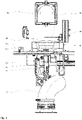
- FIG. 1 shows a perspective view of a conveyor device 10 according to the invention without attachments, connections to a housing or interfaces to other modules/components of a possible overall system.
- the conveyor device 10 laboratory vessels, in particular Petri dishes 12, are conveyed on a conveyor track 14.
- An S-shaped suction unit 16 with a filter is provided below the conveyor track 14 in order to immediately remove any germs, bacteria, etc. that may escape when the Petri dishes are opened and to prevent contamination of the environment and the conveyor device 10 in any case.
- the Suction unit 16 sucks in ambient air, which is filtered and ejected in the direction of Petri dish 12 .
- a suction device 62 Opposite the upper end of the suction unit 16 there is a suction device 62 which sucks in the air expelled from the suction unit 16, which flows around the Petri dish 12 and thereby forms a flow wall which prevents germs from escaping.
- a HEPA filter is installed in the intake device 62, which filters the air free of germs. The filtered air is then expelled again from the intake device 62 to the atmosphere. The air flow thus runs from bottom to top.
- the Petri dishes 12 are designed in a conventional manner in two parts and comprise a container 12a and a cover 12b which encompasses and closes the container 12a in some areas.
- the conveyor track 14 has an input area 20 on the left as viewed from the viewer, in which the Petri dishes 12 are introduced into the conveyor device 10 manually or automatically.
- a pusher 22 shifts the Petri dish 12 into an exit area 30 of the conveyor track 14 which adjoins the input area 20 on the right as viewed from the viewer and which will be explained in detail later.
- the output area 30 in turn is followed by an output area 70 of a further conveyor track 15 in which the Petri dishes 12 are removed from the conveyor device 10 manually or automatically.
- a barrier 72 is provided in the output area 70, which prevents the Petri dishes 12 from being transported too far. The Petri dishes 12 are stopped by the barrier 72. The Petri dishes 12 are transported away from the exit area 30 to a point in the output area 70 which is remote from the exit area 30 via a conveyor belt of the further conveyor track 15 .
- This arrangement results in a global conveying direction F, in which the pusher 22 and the conveyor belt of the conveyor track 15 with a Petri dish 12 move.
- the pusher 22 overlaps the conveyor track 14 in the manner of a clamp on one side and is driven in the conventional manner in or against the conveying direction F by an electric motor arranged under the conveyor track 14 .
- the pusher 22 is assigned exclusively to the conveyor track 14 .
- the further conveyor track 15 comprises a conveyor belt consisting of two belts.
- the conveyor belt is not continuous so that a subsequent sorting unit (not shown here) can also convey the Petri dish 12 vertically upwards.
- a position sensor module 24 is arranged on the conveyor track 14 between the input area 20 and the output area 30 and is connected to a central control unit, which is not shown here.
- This position sensor module 24 comprises two light barriers 24a and 24b arranged vertically one above the other, which are spaced apart from one another in such a way that the upper light barrier 24a detects the upper part 12a or 12b of a Petri dish 12 passing the position sensor module 24 and the lower light barrier 24b detects the lower part 12b or 12b 12a of the Petri dish 12.
- the orientation of the Petri dish 12 can be detected by the position sensor 24.
- the cover 12b of the Petri dish 12 surrounds the container 12a in some areas and therefore has a larger diameter than the container 12a. Consequently, the first of the two light barriers 24a and 24b, which is interrupted first, detects the passage of the lid 12b and the second the passage of the container 12a.
- Petri dishes 12 are introduced with the lid 12b down and the container 12a up.
- Petri dishes 12 are often stored in this orientation.
- this alignment of Petri dishes 12 is advantageous when processing samples, since the container 12a can be easily removed and put back on after processing and an additional step in which the lid 12b is removed, temporarily stored during processing and then put on again is eliminated . This will be discussed in more detail later in the explanation of the claimed method.
- a circular recess 40 is made in the conveyor track 14, which has a conically downwardly tapering lateral ring guide 41, see FIG figure 2 .
- a lifting device 32 that can be moved vertically along an axis A reaches through the recess 40 .
- the lifting device 32 includes a drive 36 for the vertical displacement movement and a support plate 34 that can be rotated about the axis A.
- the diameter of the support plate 34 is dimensioned such that it can pass through the recess 40 of the conveyor track 14 at the point of its smallest diameter with minimal play.
- An electric drive 38 for a rotational movement of the support plate 34 is arranged below the support plate 34 .
- the support plate 34 which can be moved and rotated vertically with the lifting device 32, and the recess 40 with its conically tapering lateral ring guide 41 together form a centering device for exact centering of the Petri dishes 12. The centering process will be described later in connection with the claimed method.
- a Petri dish 12 is shown that is centered exactly on the support plate 34 , the support plate 34 together with the Petri dish 12 being located above the conveyor track 14 in a height range 50 .
- the Petri dish 12 is gripped by a gripping device 52 in the height area 50, then the support plate 34 is moved downwards at least by the radius and the height of the lid plus a safety distance, in particular completely downward.
- the gripper 56 now carries only the container 12a.
- the gripper 56 rotates the container 12b by 180° and moves it translationally into a staging area. In the staging area, the sample in the container 12a is then analyzed by an analysis device, not shown here.
- the Petri dishes 12 or containers 12a of the Petri dish 12 are arranged in the staging area in the separate analysis or preparation unit.
- the gripping device 52 has a carrier arm 54 and the gripper 56 arranged at the free end of the carrier arm 54 .
- a drive 55 is provided, by means of which the carrier arm 54 can be moved forwards and backwards orthogonally to the conveying direction F.
- the gripper 56 is provided with a drive 58 with which it can be rotated about the longitudinal axis of the carrier arm 54 . Due to the translatory movement of the carrier arm 54, Petri dish containers 12a can be conveyed in a translatory manner between the height area 50 and an analysis unit. Furthermore, the orientation of a Petri dish 12 or a part of a Petri dish 12 that has been gripped can be changed with regard to the top and bottom by a rotational movement of the gripper 56 . This is explained in more detail below in connection with the method.
- the Petri dish 12c In the output area 70 is in the 1 another Petri dish 12c is shown. According to the conveying direction F, the Petri dish 12c has already gone through the analysis process and is ready to be removed from the output area 70.
- FIG. 12 shows a flow chart in which a possible course of a method according to the claimed invention is shown. In this way, the interaction of the previously described elements of the conveying device 10 is also made clear once again.
- the pusher 22 conveys 102 the Petri dish 12 along the conveyor track 14 in the direction of the output area 30.
- the Petri dish 12 passes 104 between the input area 20 and the output area 30 the position sensor 24, the connected to the control unit. Since the outer diameter of the cover 12b of the Petri dish 12 is greater than that of the container 13a, that one of the two superimposed light barriers 24a and 24b of the position sensor 24 first generates a signal 106 that is associated with the plane of the cover 12b.
- the signal 106 generated first is evaluated 110 by the control unit.
- the lift device 32 is moved 108 vertically by the drive 36 until the support plate 34 and the conveyor track 14 lie in one plane.
- the Petri dish 12 it is necessary for the Petri dish 12 to be introduced with the lid 12b at the bottom and the container 12a at the top. If the evaluation 110 by the control unit shows that the first signal generated 106 originates from the light barrier 24a and that the cover 13b is therefore aligned upwards, the processing of the Petri dish 12 is aborted 112.
- the pusher 22 moves 114 together with the Petri dish 12 over the exit area 30 away to the conveyor belt of the further conveyor track 15, then the conveyor belt takes over the transport to the output area 70.
- the pusher 22 then moves 116 back into the input area and is ready for the transport 102 of another Petri dish 12.
- the pusher 22 moves 120 together with the Petri dish 12 into the exit area 30 until the Petri dish 12 is on the support plate 34 stores 122.
- the pusher 22 moves 124 back into the input area 20 and is ready to convey 102 another Petri dish 12.
- the support plate 34 together with the Petri dish 12 is set in rotation by the drive 38 130.
- the lifting device 32 begins to move downwards 132.
- the Petri dish 12 resting on the support plate 34 is centered and finally rests 134 completely on the ring guide 41.
- the lifting device 32 moves 136 further down until the support plate 34 is located completely below the ring guide 41 . This ensures that the Petri dish 12 is centered on the ring guide 41 .
- the barcode scanner 44 reads the barcode on the laboratory vessel 12 140 and the evaluation unit 46 evaluates the barcode 142. This process 140 of reading the barcode takes place before the Petri dishes 12 are lifted.
- the barcode is either glued to the underside of the Petri dish 12, as in this case when looking at the top as the dishes are inverted, or on the side of petri dish 12. In order to be able to detect barcodes on the bottom and side equally, two barcodes are necessary.
- the Petri dish 12 is rotated by a maximum of 180° by the rotation device 38 until the laterally arranged barcode scanner 80 has detected the barcode. Once the barcode has been detected, the rotational movement is continued by a defined angle in order to align the lateral barcode to the front and thus prevent the tips of the gripper 56 from damaging the barcode.
- the lift device 32 then moves back up 144 and picks up the Petri dish 12 146. Together with the Petri dish 12 lying on the support plate 34, the lift device 32 moves further 148 until the height sensor 42 detects 150 the Petri dish 12 at a predetermined height in the height range 50 sends a signal to the central control unit 152 and the central control unit then controls the lifting device 32 to stop the movement 154.
- the central control unit then controls the gripping device 52 156 to grip the Petri dish container 12a and then move the lifting device 32 downwards by a predetermined value 158.
- the drive 55 of the gripping device 52 is then activated 160 to move the container 12a from the height range 50 to the Preparation area of the analysis or preparation unit.
- the drive rotates 162 the gripper 56 together with the container 12a by 180° so that the open side of the container 12a faces upwards.
- the gripper 56 is closed by spring force without any external influence in order to be able to reliably hold the Petri dish container 12a during the analysis or preparation process without a motor drive being necessary. This is opened by another motor.
- the carrier arm 54 with the container 13a moves again from the analysis or preparation unit 64 to the height area 50, and at the same time the drive rotates 166 the gripper 56 together with the container 12a again by 180° into the original alignment.
- the lifting device 32 moves 168 with the lid 12b under the container 12a, and the gripper 56 releases the container 12a onto the lid 12b resting on the support plate 34 170.
- the lifting device 32 now moves along the laboratory vessel 12 downwards 172 until the support plate 34 is flush with the conveyor track 14.
- the conveyor belts of the conveyor track 15 convey 174 the laboratory vessel 12 to the output area 70, where it can be removed manually or automatically 172.
Landscapes
- Health & Medical Sciences (AREA)
- Life Sciences & Earth Sciences (AREA)
- Chemical & Material Sciences (AREA)
- General Health & Medical Sciences (AREA)
- Biochemistry (AREA)
- Zoology (AREA)
- Engineering & Computer Science (AREA)
- Bioinformatics & Cheminformatics (AREA)
- Organic Chemistry (AREA)
- Wood Science & Technology (AREA)
- Analytical Chemistry (AREA)
- Immunology (AREA)
- Pathology (AREA)
- General Physics & Mathematics (AREA)
- Physics & Mathematics (AREA)
- Genetics & Genomics (AREA)
- Biomedical Technology (AREA)
- Biotechnology (AREA)
- Clinical Laboratory Science (AREA)
- General Engineering & Computer Science (AREA)
- Sustainable Development (AREA)
- Microbiology (AREA)
- Automatic Analysis And Handling Materials Therefor (AREA)
- Apparatus Associated With Microorganisms And Enzymes (AREA)
- Devices For Use In Laboratory Experiments (AREA)
Claims (16)
- Dispositif de transport (10) pour le positionnement et la fourniture de récipients de laboratoire (12 ; 12a, 12b, 12c) pour des milieux de culture, échantillons, micro-organismes, cultures cellulaires ou similaires pour l'analyse, la préparation d'échantillons et/ou manipulation d'échantillons sur un appareil (64) associé, avec au moins une première unité de transport (32) pour l'amenée et/ou l'évacuation des récipients de laboratoire (12) à partir d'une zone de départ (30) vers une zone de fourniture (60), dans lequel la première unité de transport (32) transporte verticalement le récipient de laboratoire (12) à partir de la zone de départ (30) vers une zone en hauteur (50) prédéfinie et vice versa, et une deuxième unité de transport (52) est prévue, laquelle transporte horizontalement le récipient de laboratoire (12) à partir de la zone en hauteur (50) dans la zone de fourniture (60) et vice versa, dans lequel les unités de transport effectuent respectivement uniquement un mouvement en translation du récipient de laboratoire (12) le long d'un axe (A), caractérisé en ce que la deuxième unité de transport transporte horizontalement le récipient de laboratoire à partir de la zone en hauteur (50) dans la zone de fourniture (60) et vice versa, le récipient de laboratoire (12) est retenu dans la zone de fourniture (60) pour l'analyse ou la préparation, un dispositif de centrage (34, 40) est prévu, lequel centre de manière centrale le récipient de laboratoire (12) par rapport à l'axe (A) de la première unité de transport (32), la première unité de transport (32) présente un support (34) pour le récipient de laboratoire (12), qui est orienté horizontalement, et que l'axe (A) de la première unité de transport (32) s'étend perpendiculairement à la surface de support et le dispositif de centrage (34, 40) comprend un entraînement en rotation (38) pour le support (34) et un guidage annulaire latéral (41) pour le récipient de laboratoire (12), lequel diminue de manière conique dans une direction, de sorte que pour le centrage du récipient de laboratoire, celui-ci est amené en rotation sur le support (34) autour de l'axe (A) de la première unité de transport, le support (34) est déplacé en direction de la diminution conique, ce faisant le récipient de laboratoire (12) est guidé par le guidage annulaire latéral (41) et de cette manière le récipient de laboratoire (12) est centré par rapport à l'axe (A) sur le support (34).
- Dispositif de transport selon la revendication 1, caractérisé en ce qu'une troisième unité de transport (14, 22) est prévue, laquelle transporte horizontalement un récipient de laboratoire (12) à partir d'une zone d'entrée (20) vers la zone de départ (30) et/ou qu'une quatrième unité de transport (14, 72) est prévue, laquelle transporte horizontalement un récipient de laboratoire (12) à partir de la zone de départ (30) vers une zone de sortie (70).
- Dispositif de transport selon l'une quelconque des revendications précédentes, caractérisé en ce que le support (34) est déplaçable vers le bas et le haut le long de l'axe (A) orienté verticalement et/ou que l'entraînement en rotation (38) fait partie intégrante de la première unité de transport (32).
- Dispositif de transport selon l'une quelconque des revendications précédentes, caractérisé en ce que la direction dans laquelle le récipient de laboratoire (12) est introduit dans le guidage annulaire (41) et la direction de déplacement dans la zone en hauteur (50) s'étendent de manière opposée l'une à l'autre.
- Dispositif de transport selon la revendication 3 ou 4, caractérisé en ce que l'axe de rotation du dispositif de centrage (34, 40) et l'axe vertical (A) de la première unité de transport (32) sont identiques.
- Dispositif de transport selon l'une quelconque des revendications précédentes, caractérisé en ce qu'un capteur de position (24) est monté en amont de la zone de départ (30), qui détecte l'orientation du récipient de laboratoire (12) en ce qui concerne le haut et le bas, de préférence que le récipient de laboratoire (12) est réalisé à symétrie de rotation et présente différents diamètres sur sa hauteur, le récipient de laboratoire (12) présente en particulier un contenant (12a) ouvert vers le haut avec un premier diamètre extérieur et un couvercle (12b) fermant le contenant (12a) avec un deuxième diamètre extérieur, dans lequel le deuxième diamètre extérieur du couvercle (12b) est plus grand que le premier diamètre extérieur du contenant (12a).
- Dispositif de transport selon la revendication 5 et 6, dans lequel une troisième unité de transport (14, 22) est prévue selon la revendication 2, caractérisé en ce que le capteur de position (24) est inséré dans la voie de transport de la troisième unité de transport (14, 22), en particulier que deux barrières lumineuses (24a, 24b) orientées transversalement par rapport à la direction de transport F de la troisième unité de transport (14, 22) sont prévues, qui sont associées respectivement à un diamètre extérieur du récipient de laboratoire (12), de sorte que la barrière lumineuse (24a, 24b) au niveau de laquelle le plus grand diamètre extérieur du récipient de laboratoire (12b) entre en premier, génère un signal en premier, et ensuite de manière décalée dans le temps l'autre barrière lumineuse, au niveau de laquelle le plus petit diamètre extérieur du récipient de laboratoire (12a) entre, moyennant quoi l'orientation du récipient de laboratoire (12) peut être déterminée.
- Dispositif de transport selon l'une quelconque des revendications précédentes, caractérisé en ce que la deuxième unité de transport (52) est réalisée par un bras de transport (54) avec un élément de préhension (56) sur l'extrémité libre, en particulier que l'élément de préhension (56) est monté en rotation dans le bras de transport (54) et entraîné (55) de sorte que celui-ci peut amener en rotation et déplacer horizontalement la partie (12a) saisie du récipient de laboratoire (12) dans une orientation prédéfinie par rapport à l'appareil d'analyse (64), en particulier de 180°.
- Dispositif de transport selon l'une quelconque des revendications précédentes, caractérisé en ce qu'un système d'aspiration (62) est prévu, lequel est actif au moins entre la zone en hauteur (50) et la zone de fourniture (60).
- Dispositif de transport selon l'une quelconque des revendications précédentes, caractérisé en ce qu'un capteur (42) est prévu, qui détecte quand le récipient de laboratoire (12) déplacé verticalement par la première unité de transport (32) a atteint une hauteur (H) prédéfinie.
- Procédé pour le positionnement et la fourniture de récipients de laboratoire (12) pour des échantillons avec un dispositif de transport (10) selon l'une quelconque des revendications précédentes, caractérisé en ce qu'avant le transport par la première unité de transport (32) à l'intérieur de la zone de départ (30) l'orientation du récipient de laboratoire (12) est détectée, dans lequel lorsque l'orientation correspond à l'orientation prédéfinie, le récipient de laboratoire (12) est centré dans la zone de départ (30) et, lorsque l'orientation du récipient de laboratoire (12) ne correspond pas à l'orientation prédéfinie, le récipient de laboratoire (12) est transporté à nouveau à l'extérieur de la zone de départ (30), en particulier par l'intermédiaire de la quatrième unité de transport (14, 72) selon la revendication 2, de préférence que le récipient de laboratoire (12) est centré par rapport à l'axe vertical (A) avant le déplacement dans la zone en hauteur (50).
- Procédé selon la revendication 11, caractérisé en ce que le récipient de laboratoire (12) est ouvert avant l'analyse et refermé après l'analyse.
- Procédé selon la revendication 2 et selon l'une quelconque des revendications 11 ou 12, caractérisé en ce qu'en fonctionnement normal les récipients de laboratoire (12) sont transportés dans la zone de départ (30) par l'intermédiaire de la troisième unité de transport (14, 22), les récipients de laboratoire (12) sont transportés par l'intermédiaire de la première unité de transport (32) hors de la zone de départ (30) dans la zone en hauteur (50), les récipients de laboratoire (12) sont transportés dans la zone de fourniture (60) par l'intermédiaire de la deuxième unité de transport (52) et les récipients de laboratoire (12) sont transportés hors de la zone de départ (30) dans la zone de sortie (70) par l'intermédiaire de la quatrième unité de transport (15).
- Procédé selon l'une quelconque des revendications 11 à 13, caractérisé en ce que par l'intermédiaire d'une unité de commande (80) coopérant avec le capteur de position (24), seuls les récipients de laboratoire (12) orientés de manière prédéfinie restent dans la zone de départ (30) pour le déplacement dans la zone de fourniture, et tous les autres récipients de laboratoire (12) sont à nouveau sortis de la zone de départ (30), en particulier par la troisième unité de transport (14, 22) selon la revendication 2.
- Procédé selon l'une quelconque des revendications 11 à 14, caractérisé en ce qu'au moins une partie (12a) du récipient de laboratoire (12) est saisie à partir de la zone en hauteur (50) par la deuxième unité de transport (52) et cette partie (12a) du récipient de laboratoire (12) est amenée à la zone de fourniture (60), cette partie (12a) est maintenue pendant l'analyse et après l'analyse ramenée dans la zone de fourniture (60).
- Procédé selon l'une quelconque des revendications 11 à 15, caractérisé en ce que le récipient de laboratoire (12) est introduit dans le dispositif de centrage (34, 40) sous l'effet d'une rotation du support (34) avec le récipient de laboratoire (12).
Applications Claiming Priority (2)
| Application Number | Priority Date | Filing Date | Title |
|---|---|---|---|
| DE102016105683.9A DE102016105683A1 (de) | 2016-03-29 | 2016-03-29 | Fördervorrichtung |
| PCT/EP2017/056305 WO2017167585A1 (fr) | 2016-03-29 | 2017-03-16 | Dispositif de transport |
Publications (2)
| Publication Number | Publication Date |
|---|---|
| EP3436832A1 EP3436832A1 (fr) | 2019-02-06 |
| EP3436832B1 true EP3436832B1 (fr) | 2022-08-03 |
Family
ID=58455019
Family Applications (1)
| Application Number | Title | Priority Date | Filing Date |
|---|---|---|---|
| EP17714403.7A Active EP3436832B1 (fr) | 2016-03-29 | 2017-03-16 | Dispositif de transport |
Country Status (7)
| Country | Link |
|---|---|
| US (1) | US11307210B2 (fr) |
| EP (1) | EP3436832B1 (fr) |
| JP (1) | JP7008635B2 (fr) |
| CN (1) | CN108885222B (fr) |
| AU (1) | AU2017244065B2 (fr) |
| DE (1) | DE102016105683A1 (fr) |
| WO (1) | WO2017167585A1 (fr) |
Families Citing this family (6)
| Publication number | Priority date | Publication date | Assignee | Title |
|---|---|---|---|---|
| CN112180072A (zh) * | 2020-10-27 | 2021-01-05 | 重庆正道路桥工程质量检测中心有限公司 | 一种混凝土动态离析检测设备 |
| EP4001395A3 (fr) * | 2020-11-02 | 2022-07-27 | Airamatrix Private Limited | Système et procédé de gestion automatique d'échantillon(s) organique(s) |
| DE102020130016B4 (de) | 2020-11-13 | 2024-09-05 | Accurro Gmbh | Vorrichtung und Verfahren zum Messen der Verkeimung eines kontrollierten, nahezu keimfreien Raumes, insbesondere eines Reinraumes, mittels einer in einer Petrischale befindlichen, Keime detektierenden Nährlösung |
| CN113070116A (zh) * | 2021-04-26 | 2021-07-06 | 陈疑 | 一种便于存放厌氧培养基的操作台 |
| CN114054120B (zh) * | 2021-11-24 | 2022-10-11 | 哈尔滨星云医学检验所有限公司 | 一种实验室自动化系统 |
| CN117204237B (zh) * | 2023-10-09 | 2025-08-08 | 南通海关综合技术中心(江苏国际旅行卫生保健中心南通分中心、南通海关口岸门诊部) | 一种植物检疫用光照培养箱 |
Family Cites Families (19)
| Publication number | Priority date | Publication date | Assignee | Title |
|---|---|---|---|---|
| CH663382A5 (de) | 1983-11-29 | 1987-12-15 | Tecnomara Ag | Geraet zum markieren von petrischalen. |
| JPS61115483A (ja) * | 1984-11-09 | 1986-06-03 | Hitachi Electronics Eng Co Ltd | シャーレの支持装置 |
| JPH04248980A (ja) * | 1991-01-31 | 1992-09-04 | Dainippon Seiki:Kk | 自動微生物試験装置 |
| JP3382990B2 (ja) | 1993-02-01 | 2003-03-04 | 株式会社大日本精機 | 自動培地分注装置 |
| JP2002098704A (ja) | 2000-09-25 | 2002-04-05 | Olympus Optical Co Ltd | 細菌類の自動分析装置 |
| US7468161B2 (en) * | 2002-04-15 | 2008-12-23 | Ventana Medical Systems, Inc. | Automated high volume slide processing system |
| US7670555B2 (en) * | 2006-09-08 | 2010-03-02 | Rex A. Hoover | Parallel gripper for handling multiwell plate |
| AU2008204729B2 (en) | 2007-01-12 | 2013-09-05 | Autobio Diagnostics Co., Ltd | Method and apparatus for orientating a solid growth culture medium plate |
| JP5372551B2 (ja) * | 2008-10-28 | 2013-12-18 | シスメックス株式会社 | 検体処理システム及び検体情報表示装置 |
| FR2939444B1 (fr) | 2008-12-10 | 2011-02-04 | Aes Chemunex | Dispositif de distribution d'un produit dans une boite de petri. |
| DE102010060634B4 (de) | 2010-11-17 | 2013-07-25 | Andreas Hettich Gmbh & Co. Kg | Klimatisierungsraum für eine zeitgesteuerte Lagerung von Proben und Verfahren zur zeitgesteuerten Lagerung von Proben |
| DE102010044125A1 (de) * | 2010-11-18 | 2012-05-24 | Systec Gmbh Labor-Systemtechnik | Petrischalen-Befüllvorrichtung |
| JP5775344B2 (ja) | 2011-03-31 | 2015-09-09 | ラボテック株式会社 | 検体作製装置 |
| ES2632121T3 (es) | 2011-04-29 | 2017-09-11 | Bd Kiestra B.V. | Dispositivo dispensador de discos, recipiente tubular para uso en dicho dispositivo dispensador de discos y método para dispensar discos |
| DE102011083757A1 (de) * | 2011-09-29 | 2013-04-04 | Krones Aktiengesellschaft | Triggerlichtgitter und Verfahren zur Positionsbestimmung von Behältern |
| EP2589968A1 (fr) | 2011-11-04 | 2013-05-08 | Roche Diagnostics GmbH | Système de distribution d'échantillons de laboratoire, système de laboratoire et procédé de fonctionnement |
| ITMI20130692A1 (it) * | 2013-04-26 | 2014-10-27 | Copan Italia Spa | Dispositivo e procedimento per il processamento automatico di piastre di coltura per campioni microbiologici |
| DE202014101722U1 (de) | 2014-04-11 | 2015-04-14 | Krones Aktiengesellschaft | Behälterhandhabungsvorrichtung zum Halten, Greifen und/oder Drehen von Behältern |
| US11041871B2 (en) | 2014-04-16 | 2021-06-22 | Bd Kiestra B.V. | System and method for incubation and reading of biological cultures |
-
2016
- 2016-03-29 DE DE102016105683.9A patent/DE102016105683A1/de active Pending
-
2017
- 2017-03-16 WO PCT/EP2017/056305 patent/WO2017167585A1/fr not_active Ceased
- 2017-03-16 EP EP17714403.7A patent/EP3436832B1/fr active Active
- 2017-03-16 US US16/086,589 patent/US11307210B2/en active Active
- 2017-03-16 AU AU2017244065A patent/AU2017244065B2/en active Active
- 2017-03-16 CN CN201780020961.0A patent/CN108885222B/zh active Active
- 2017-03-16 JP JP2018550344A patent/JP7008635B2/ja active Active
Also Published As
| Publication number | Publication date |
|---|---|
| US20190101552A1 (en) | 2019-04-04 |
| EP3436832A1 (fr) | 2019-02-06 |
| WO2017167585A1 (fr) | 2017-10-05 |
| CN108885222B (zh) | 2022-06-10 |
| AU2017244065A1 (en) | 2018-11-22 |
| JP7008635B2 (ja) | 2022-01-25 |
| CN108885222A (zh) | 2018-11-23 |
| US11307210B2 (en) | 2022-04-19 |
| AU2017244065B2 (en) | 2021-04-29 |
| DE102016105683A1 (de) | 2017-10-05 |
| JP2019512707A (ja) | 2019-05-16 |
Similar Documents
| Publication | Publication Date | Title |
|---|---|---|
| EP3436832A1 (fr) | Dispositif de transport | |
| EP2027926B1 (fr) | Appareil de fonctionnement de matériel biologique | |
| EP2927163B1 (fr) | Dispositif de transport vertical, système de distribution d'échantillons et système d'automatisation de laboratoire | |
| EP2092311B1 (fr) | Dispositif d'inspection de bouteilles ou recipients analogues | |
| DE4212821C2 (de) | Vorrichtung zum Entfernen eines Verschlusses von der Öffnung eines Behälters und zur Entnahme von flüssigen Inhalten | |
| EP1496365B1 (fr) | Dispositif et procédé de transport d'objets | |
| DE602004013176T2 (de) | Vorrichtung zur durchführung von analysen in biologischen flüssigkeiten und damit verbundenes verfahren | |
| EP2702386B1 (fr) | Dispositif de poinçonnage pourvu d'une unité de préhension | |
| DE102015221024B3 (de) | Nadelführung mit Zentrierung für Septum-Piercing | |
| CH706811A1 (de) | Mikroplatten-Reader mit Deckelabheber für Mikroplatten. | |
| EP2927167A1 (fr) | Dispositif d'envoi, système de distribution d'échantillons et système d'automatisation de laboratoire | |
| DE102012013022A1 (de) | Vorrichtung zur automatisierten Handhabung von Werkstücken | |
| EP3175248A2 (fr) | Appareil pour préparer une pluralité d'échantillons en vue d'un procédé d'analyse | |
| DE102016111042A1 (de) | Greifvorrichtung | |
| EP3216517B1 (fr) | Procede de melange d'un liquide dans un appareil d'analyse automatique | |
| DE102016103639A1 (de) | Zuführvorrichtung | |
| WO2024251773A1 (fr) | Installation de laboratoire de diagnostic in vitro comprenant des dispositifs d'analyse et un robot de manipulation avec au moins deux bras de préhension et une table avec une surface de support | |
| DE102012013029A1 (de) | Vorrichtung zur automatischen Handhabung von ungeordneten Werkstücken | |
| WO2018095685A1 (fr) | Système et procédé de fermeture automatique de récipients à échantillon | |
| EP3270167B1 (fr) | Transport de récipients de liquides dans un appareil d'analyse automatique | |
| DE102014110684A1 (de) | Anordnung zur Vorbereitung einer Vielzahl von Proben für ein analytisches Verfahren | |
| DE102019205185A1 (de) | Rohrpoststation mit einem Werkzeugwechsler | |
| WO2013060725A1 (fr) | Procédé de chargement automatique d'une centrifugeuse comprenant des contenants d'échantillons | |
| WO2021148384A1 (fr) | Appareil et procédé d'identification, de mesure et de positionnement de marchandises de détail | |
| WO2025257033A1 (fr) | Unité de support pour le transport d'un objet |
Legal Events
| Date | Code | Title | Description |
|---|---|---|---|
| STAA | Information on the status of an ep patent application or granted ep patent |
Free format text: STATUS: UNKNOWN |
|
| STAA | Information on the status of an ep patent application or granted ep patent |
Free format text: STATUS: THE INTERNATIONAL PUBLICATION HAS BEEN MADE |
|
| PUAI | Public reference made under article 153(3) epc to a published international application that has entered the european phase |
Free format text: ORIGINAL CODE: 0009012 |
|
| STAA | Information on the status of an ep patent application or granted ep patent |
Free format text: STATUS: REQUEST FOR EXAMINATION WAS MADE |
|
| 17P | Request for examination filed |
Effective date: 20181015 |
|
| AK | Designated contracting states |
Kind code of ref document: A1 Designated state(s): AL AT BE BG CH CY CZ DE DK EE ES FI FR GB GR HR HU IE IS IT LI LT LU LV MC MK MT NL NO PL PT RO RS SE SI SK SM TR |
|
| AX | Request for extension of the european patent |
Extension state: BA ME |
|
| DAV | Request for validation of the european patent (deleted) | ||
| DAX | Request for extension of the european patent (deleted) | ||
| GRAP | Despatch of communication of intention to grant a patent |
Free format text: ORIGINAL CODE: EPIDOSNIGR1 |
|
| STAA | Information on the status of an ep patent application or granted ep patent |
Free format text: STATUS: GRANT OF PATENT IS INTENDED |
|
| INTG | Intention to grant announced |
Effective date: 20220217 |
|
| RIN1 | Information on inventor provided before grant (corrected) |
Inventor name: EBERLE, KLAUS-GUENTER |
|
| GRAJ | Information related to disapproval of communication of intention to grant by the applicant or resumption of examination proceedings by the epo deleted |
Free format text: ORIGINAL CODE: EPIDOSDIGR1 |
|
| STAA | Information on the status of an ep patent application or granted ep patent |
Free format text: STATUS: REQUEST FOR EXAMINATION WAS MADE |
|
| GRAS | Grant fee paid |
Free format text: ORIGINAL CODE: EPIDOSNIGR3 |
|
| STAA | Information on the status of an ep patent application or granted ep patent |
Free format text: STATUS: GRANT OF PATENT IS INTENDED |
|
| GRAP | Despatch of communication of intention to grant a patent |
Free format text: ORIGINAL CODE: EPIDOSNIGR1 |
|
| INTC | Intention to grant announced (deleted) | ||
| GRAA | (expected) grant |
Free format text: ORIGINAL CODE: 0009210 |
|
| STAA | Information on the status of an ep patent application or granted ep patent |
Free format text: STATUS: THE PATENT HAS BEEN GRANTED |
|
| INTG | Intention to grant announced |
Effective date: 20220622 |
|
| AK | Designated contracting states |
Kind code of ref document: B1 Designated state(s): AL AT BE BG CH CY CZ DE DK EE ES FI FR GB GR HR HU IE IS IT LI LT LU LV MC MK MT NL NO PL PT RO RS SE SI SK SM TR |
|
| REG | Reference to a national code |
Ref country code: AT Ref legal event code: REF Ref document number: 1509152 Country of ref document: AT Kind code of ref document: T Effective date: 20220815 Ref country code: CH Ref legal event code: EP |
|
| REG | Reference to a national code |
Ref country code: DE Ref legal event code: R096 Ref document number: 502017013557 Country of ref document: DE |
|
| REG | Reference to a national code |
Ref country code: IE Ref legal event code: FG4D Free format text: LANGUAGE OF EP DOCUMENT: GERMAN |
|
| REG | Reference to a national code |
Ref country code: LT Ref legal event code: MG9D |
|
| REG | Reference to a national code |
Ref country code: NL Ref legal event code: MP Effective date: 20220803 |
|
| PG25 | Lapsed in a contracting state [announced via postgrant information from national office to epo] |
Ref country code: SE Free format text: LAPSE BECAUSE OF FAILURE TO SUBMIT A TRANSLATION OF THE DESCRIPTION OR TO PAY THE FEE WITHIN THE PRESCRIBED TIME-LIMIT Effective date: 20220803 Ref country code: RS Free format text: LAPSE BECAUSE OF FAILURE TO SUBMIT A TRANSLATION OF THE DESCRIPTION OR TO PAY THE FEE WITHIN THE PRESCRIBED TIME-LIMIT Effective date: 20220803 Ref country code: PT Free format text: LAPSE BECAUSE OF FAILURE TO SUBMIT A TRANSLATION OF THE DESCRIPTION OR TO PAY THE FEE WITHIN THE PRESCRIBED TIME-LIMIT Effective date: 20221205 Ref country code: NO Free format text: LAPSE BECAUSE OF FAILURE TO SUBMIT A TRANSLATION OF THE DESCRIPTION OR TO PAY THE FEE WITHIN THE PRESCRIBED TIME-LIMIT Effective date: 20221103 Ref country code: NL Free format text: LAPSE BECAUSE OF FAILURE TO SUBMIT A TRANSLATION OF THE DESCRIPTION OR TO PAY THE FEE WITHIN THE PRESCRIBED TIME-LIMIT Effective date: 20220803 Ref country code: LV Free format text: LAPSE BECAUSE OF FAILURE TO SUBMIT A TRANSLATION OF THE DESCRIPTION OR TO PAY THE FEE WITHIN THE PRESCRIBED TIME-LIMIT Effective date: 20220803 Ref country code: LT Free format text: LAPSE BECAUSE OF FAILURE TO SUBMIT A TRANSLATION OF THE DESCRIPTION OR TO PAY THE FEE WITHIN THE PRESCRIBED TIME-LIMIT Effective date: 20220803 Ref country code: FI Free format text: LAPSE BECAUSE OF FAILURE TO SUBMIT A TRANSLATION OF THE DESCRIPTION OR TO PAY THE FEE WITHIN THE PRESCRIBED TIME-LIMIT Effective date: 20220803 Ref country code: ES Free format text: LAPSE BECAUSE OF FAILURE TO SUBMIT A TRANSLATION OF THE DESCRIPTION OR TO PAY THE FEE WITHIN THE PRESCRIBED TIME-LIMIT Effective date: 20220803 |
|
| PG25 | Lapsed in a contracting state [announced via postgrant information from national office to epo] |
Ref country code: PL Free format text: LAPSE BECAUSE OF FAILURE TO SUBMIT A TRANSLATION OF THE DESCRIPTION OR TO PAY THE FEE WITHIN THE PRESCRIBED TIME-LIMIT Effective date: 20220803 Ref country code: IS Free format text: LAPSE BECAUSE OF FAILURE TO SUBMIT A TRANSLATION OF THE DESCRIPTION OR TO PAY THE FEE WITHIN THE PRESCRIBED TIME-LIMIT Effective date: 20221203 Ref country code: HR Free format text: LAPSE BECAUSE OF FAILURE TO SUBMIT A TRANSLATION OF THE DESCRIPTION OR TO PAY THE FEE WITHIN THE PRESCRIBED TIME-LIMIT Effective date: 20220803 Ref country code: GR Free format text: LAPSE BECAUSE OF FAILURE TO SUBMIT A TRANSLATION OF THE DESCRIPTION OR TO PAY THE FEE WITHIN THE PRESCRIBED TIME-LIMIT Effective date: 20221104 |
|
| PG25 | Lapsed in a contracting state [announced via postgrant information from national office to epo] |
Ref country code: SM Free format text: LAPSE BECAUSE OF FAILURE TO SUBMIT A TRANSLATION OF THE DESCRIPTION OR TO PAY THE FEE WITHIN THE PRESCRIBED TIME-LIMIT Effective date: 20220803 Ref country code: RO Free format text: LAPSE BECAUSE OF FAILURE TO SUBMIT A TRANSLATION OF THE DESCRIPTION OR TO PAY THE FEE WITHIN THE PRESCRIBED TIME-LIMIT Effective date: 20220803 Ref country code: DK Free format text: LAPSE BECAUSE OF FAILURE TO SUBMIT A TRANSLATION OF THE DESCRIPTION OR TO PAY THE FEE WITHIN THE PRESCRIBED TIME-LIMIT Effective date: 20220803 Ref country code: CZ Free format text: LAPSE BECAUSE OF FAILURE TO SUBMIT A TRANSLATION OF THE DESCRIPTION OR TO PAY THE FEE WITHIN THE PRESCRIBED TIME-LIMIT Effective date: 20220803 |
|
| REG | Reference to a national code |
Ref country code: DE Ref legal event code: R097 Ref document number: 502017013557 Country of ref document: DE |
|
| PG25 | Lapsed in a contracting state [announced via postgrant information from national office to epo] |
Ref country code: SK Free format text: LAPSE BECAUSE OF FAILURE TO SUBMIT A TRANSLATION OF THE DESCRIPTION OR TO PAY THE FEE WITHIN THE PRESCRIBED TIME-LIMIT Effective date: 20220803 Ref country code: EE Free format text: LAPSE BECAUSE OF FAILURE TO SUBMIT A TRANSLATION OF THE DESCRIPTION OR TO PAY THE FEE WITHIN THE PRESCRIBED TIME-LIMIT Effective date: 20220803 |
|
| PLBE | No opposition filed within time limit |
Free format text: ORIGINAL CODE: 0009261 |
|
| STAA | Information on the status of an ep patent application or granted ep patent |
Free format text: STATUS: NO OPPOSITION FILED WITHIN TIME LIMIT |
|
| PG25 | Lapsed in a contracting state [announced via postgrant information from national office to epo] |
Ref country code: AL Free format text: LAPSE BECAUSE OF FAILURE TO SUBMIT A TRANSLATION OF THE DESCRIPTION OR TO PAY THE FEE WITHIN THE PRESCRIBED TIME-LIMIT Effective date: 20220803 |
|
| 26N | No opposition filed |
Effective date: 20230504 |
|
| P01 | Opt-out of the competence of the unified patent court (upc) registered |
Effective date: 20230530 |
|
| PG25 | Lapsed in a contracting state [announced via postgrant information from national office to epo] |
Ref country code: SI Free format text: LAPSE BECAUSE OF FAILURE TO SUBMIT A TRANSLATION OF THE DESCRIPTION OR TO PAY THE FEE WITHIN THE PRESCRIBED TIME-LIMIT Effective date: 20220803 |
|
| PG25 | Lapsed in a contracting state [announced via postgrant information from national office to epo] |
Ref country code: MC Free format text: LAPSE BECAUSE OF FAILURE TO SUBMIT A TRANSLATION OF THE DESCRIPTION OR TO PAY THE FEE WITHIN THE PRESCRIBED TIME-LIMIT Effective date: 20220803 |
|
| REG | Reference to a national code |
Ref country code: CH Ref legal event code: PL |
|
| REG | Reference to a national code |
Ref country code: BE Ref legal event code: MM Effective date: 20230331 |
|
| PG25 | Lapsed in a contracting state [announced via postgrant information from national office to epo] |
Ref country code: LU Free format text: LAPSE BECAUSE OF NON-PAYMENT OF DUE FEES Effective date: 20230316 |
|
| REG | Reference to a national code |
Ref country code: IE Ref legal event code: MM4A |
|
| PG25 | Lapsed in a contracting state [announced via postgrant information from national office to epo] |
Ref country code: LI Free format text: LAPSE BECAUSE OF NON-PAYMENT OF DUE FEES Effective date: 20230331 Ref country code: IE Free format text: LAPSE BECAUSE OF NON-PAYMENT OF DUE FEES Effective date: 20230316 Ref country code: CH Free format text: LAPSE BECAUSE OF NON-PAYMENT OF DUE FEES Effective date: 20230331 |
|
| PG25 | Lapsed in a contracting state [announced via postgrant information from national office to epo] |
Ref country code: BE Free format text: LAPSE BECAUSE OF NON-PAYMENT OF DUE FEES Effective date: 20230331 |
|
| REG | Reference to a national code |
Ref country code: AT Ref legal event code: MM01 Ref document number: 1509152 Country of ref document: AT Kind code of ref document: T Effective date: 20230316 |
|
| PG25 | Lapsed in a contracting state [announced via postgrant information from national office to epo] |
Ref country code: IT Free format text: LAPSE BECAUSE OF FAILURE TO SUBMIT A TRANSLATION OF THE DESCRIPTION OR TO PAY THE FEE WITHIN THE PRESCRIBED TIME-LIMIT Effective date: 20220803 |
|
| PG25 | Lapsed in a contracting state [announced via postgrant information from national office to epo] |
Ref country code: AT Free format text: LAPSE BECAUSE OF NON-PAYMENT OF DUE FEES Effective date: 20230316 |
|
| PG25 | Lapsed in a contracting state [announced via postgrant information from national office to epo] |
Ref country code: AT Free format text: LAPSE BECAUSE OF NON-PAYMENT OF DUE FEES Effective date: 20230316 |
|
| PG25 | Lapsed in a contracting state [announced via postgrant information from national office to epo] |
Ref country code: BG Free format text: LAPSE BECAUSE OF FAILURE TO SUBMIT A TRANSLATION OF THE DESCRIPTION OR TO PAY THE FEE WITHIN THE PRESCRIBED TIME-LIMIT Effective date: 20220803 |
|
| PG25 | Lapsed in a contracting state [announced via postgrant information from national office to epo] |
Ref country code: BG Free format text: LAPSE BECAUSE OF FAILURE TO SUBMIT A TRANSLATION OF THE DESCRIPTION OR TO PAY THE FEE WITHIN THE PRESCRIBED TIME-LIMIT Effective date: 20220803 |
|
| REG | Reference to a national code |
Ref country code: DE Ref legal event code: R081 Ref document number: 502017013557 Country of ref document: DE Owner name: ANDREAS HETTICH GMBH, DE Free format text: FORMER OWNER: ANDREAS HETTICH GMBH & CO. KG, 78532 TUTTLINGEN, DE |
|
| PGFP | Annual fee paid to national office [announced via postgrant information from national office to epo] |
Ref country code: DE Payment date: 20250328 Year of fee payment: 9 |
|
| PGFP | Annual fee paid to national office [announced via postgrant information from national office to epo] |
Ref country code: FR Payment date: 20250324 Year of fee payment: 9 |
|
| PGFP | Annual fee paid to national office [announced via postgrant information from national office to epo] |
Ref country code: GB Payment date: 20250324 Year of fee payment: 9 |
|
| PG25 | Lapsed in a contracting state [announced via postgrant information from national office to epo] |
Ref country code: CY Free format text: LAPSE BECAUSE OF FAILURE TO SUBMIT A TRANSLATION OF THE DESCRIPTION OR TO PAY THE FEE WITHIN THE PRESCRIBED TIME-LIMIT; INVALID AB INITIO Effective date: 20170316 |
|
| PG25 | Lapsed in a contracting state [announced via postgrant information from national office to epo] |
Ref country code: HU Free format text: LAPSE BECAUSE OF FAILURE TO SUBMIT A TRANSLATION OF THE DESCRIPTION OR TO PAY THE FEE WITHIN THE PRESCRIBED TIME-LIMIT; INVALID AB INITIO Effective date: 20170316 |
|
| PG25 | Lapsed in a contracting state [announced via postgrant information from national office to epo] |
Ref country code: TR Free format text: LAPSE BECAUSE OF FAILURE TO SUBMIT A TRANSLATION OF THE DESCRIPTION OR TO PAY THE FEE WITHIN THE PRESCRIBED TIME-LIMIT Effective date: 20220803 |