EP3437155B1 - Dispositif d'echange de chaleur pour module de batteries, procédé de production de celui et module de batteries - Google Patents
Dispositif d'echange de chaleur pour module de batteries, procédé de production de celui et module de batteries Download PDFInfo
- Publication number
- EP3437155B1 EP3437155B1 EP17709679.9A EP17709679A EP3437155B1 EP 3437155 B1 EP3437155 B1 EP 3437155B1 EP 17709679 A EP17709679 A EP 17709679A EP 3437155 B1 EP3437155 B1 EP 3437155B1
- Authority
- EP
- European Patent Office
- Prior art keywords
- temperature control
- flow
- deflection unit
- flow space
- spacer elements
- Prior art date
- Legal status (The legal status is an assumption and is not a legal conclusion. Google has not performed a legal analysis and makes no representation as to the accuracy of the status listed.)
- Active
Links
Images




Classifications
-
- H—ELECTRICITY
- H01—ELECTRIC ELEMENTS
- H01M—PROCESSES OR MEANS, e.g. BATTERIES, FOR THE DIRECT CONVERSION OF CHEMICAL ENERGY INTO ELECTRICAL ENERGY
- H01M10/00—Secondary cells; Manufacture thereof
- H01M10/60—Heating or cooling; Temperature control
- H01M10/65—Means for temperature control structurally associated with the cells
- H01M10/656—Means for temperature control structurally associated with the cells characterised by the type of heat-exchange fluid
- H01M10/6567—Liquids
- H01M10/6568—Liquids characterised by flow circuits, e.g. loops, located externally to the cells or cell casings
-
- H—ELECTRICITY
- H01—ELECTRIC ELEMENTS
- H01M—PROCESSES OR MEANS, e.g. BATTERIES, FOR THE DIRECT CONVERSION OF CHEMICAL ENERGY INTO ELECTRICAL ENERGY
- H01M10/00—Secondary cells; Manufacture thereof
- H01M10/60—Heating or cooling; Temperature control
- H01M10/65—Means for temperature control structurally associated with the cells
- H01M10/655—Solid structures for heat exchange or heat conduction
- H01M10/6556—Solid parts with flow channel passages or pipes for heat exchange
-
- Y—GENERAL TAGGING OF NEW TECHNOLOGICAL DEVELOPMENTS; GENERAL TAGGING OF CROSS-SECTIONAL TECHNOLOGIES SPANNING OVER SEVERAL SECTIONS OF THE IPC; TECHNICAL SUBJECTS COVERED BY FORMER USPC CROSS-REFERENCE ART COLLECTIONS [XRACs] AND DIGESTS
- Y02—TECHNOLOGIES OR APPLICATIONS FOR MITIGATION OR ADAPTATION AGAINST CLIMATE CHANGE
- Y02E—REDUCTION OF GREENHOUSE GAS [GHG] EMISSIONS, RELATED TO ENERGY GENERATION, TRANSMISSION OR DISTRIBUTION
- Y02E60/00—Enabling technologies; Technologies with a potential or indirect contribution to GHG emissions mitigation
- Y02E60/10—Energy storage using batteries
Definitions
- the invention is based on a temperature control device of a battery module according to the preamble of the independent claim.
- the present invention also relates to a method for producing a temperature control device and a battery module with such a temperature control device.
- a temperature control device through which a temperature control fluid flows is arranged on the battery module, the temperature control fluid being introduced into a flow space of the temperature control device by means of an inlet and from the flow space by means of an outlet is discharged.
- the heat from the battery cells is transferred via the temperature control device to the temperature control fluid flowing in the flow space.
- a plate assembly for a heat exchanger of a battery assembly has at least two essentially planar elements that form an intermediate space and are preferably formed from plastic, the at least two planar elements being spaced apart from one another by spacers to form the intermediate space.
- a coolant can flow through the intermediate space.
- the plate assembly has a wall within the intermediate space which, together with the spacers, defines the flow field of the coolant within the intermediate space.
- the planar elements of the plate assembly have openings for the inflow and outflow of the coolant.
- the cooling device has a cooling plate arrangement with a first metal sheet and a second metal sheet, which are connected to one another by means of a roll cladding process.
- the first metal sheet and the second metal sheet are connected to one another with the formation of cooling fluid channels, which are designed as cavities between the two metal sheets, the first metal sheet and the second metal sheet being spaced apart from one another in the area of the cooling fluid channels.
- the DE 10 2014 102 954 A1 discloses a microchannel cooling fin for a battery module that includes a metal plate assembly defining a plurality of cooling channels. Furthermore, the microchannel cooling fin has an inlet part for introducing a liquid coolant into the plurality of cooling channels and an outlet part from which the coolant leaves the plurality of cooling channels.
- the DE 10 2012 023 316 A1 discloses a temperature control device with an essentially cuboid base body, which is designed to be thermally conductively connectable to energy storage units, and at least one fluid channel which is at least partially guided through the base body in order to guide a temperature control fluid. Furthermore, the temperature control device has a plurality of depressions and / or projections which are arranged on a lateral surface of the base body.
- KR 2014 0026961 discloses a temperature control device of a battery module with a closed flow space having a plurality of spacer elements, the temperature control device having a current deflection unit arranged within the flow space.
- the battery module with the temperature control device with the features of the independent claim has the advantage that a temperature control fluid flowing through a flow space of the temperature control device can be guided by means of a flow deflection unit arranged within the flow space and a large number of spacer elements in such a way that a more uniform flow of the temperature control fluid in the case of a reduced Pressure loss within the flow space is possible in comparison to temperature control devices known from the prior art and at the same time the occurrence of dead areas can be reduced.
- a temperature control device has the advantage compared to temperature control devices forming defined cooling channels that, due to the larger flow space, temperature control fluid can flow through the temperature control device over a larger area and the spacer elements arranged in the flow space ensure a more turbulent flow with a higher Reynolds number, whereby the heat transport properties can be further improved and thus heat can also be dissipated more efficiently. This makes it possible to reliably cool the battery cells of a battery module.
- a temperature control device for a battery module has an essentially closed flow space with a large number of spacer elements.
- the spacer elements are arranged within the flow space.
- the temperature control device has a flow deflection unit arranged within the flow space.
- the flow deflection unit has a first end and a second end, the flow deflection unit having a longitudinal direction running along the flow deflection unit from the first end to the second end.
- the flow deflection unit forms a first side surface and a second side surface, which are arranged along the longitudinal direction on mutually opposite sides of the flow deflection unit.
- the first side surface and the second side surface are arranged at least in sections directly adjacent to a spacer element.
- a substantially closed flow space should be understood to mean that the flow space is sealed off in a fluid-tight manner apart from connections for introducing or discharging a temperature control fluid into the flow space or out of the flow space.
- the flow space for the temperature control fluid is sealed off.
- the temperature control device has a first temperature control body and a second temperature control body, which are each formed essentially from a planar base body.
- the first temperature control body has a first surface and the second temperature control body has a second surface, which are spaced apart from one another by means of the plurality of spacer elements.
- the first temperature control body and the second temperature control body form the flow space of the temperature control device.
- the first surface and the second surface delimit the flow space.
- the first surface of the first temperature control body, which is essentially formed from a planar base body, and the second surface of the second temperature control body, which is essentially formed from a planar base body are arranged parallel to one another.
- the spacer elements preferably each contact the first surface and / or the second surface. In particular, the spacer elements are each connected to the first surface and / or the second surface.
- planar design of the two temperature control bodies means that no flow deflections causing the pressure loss are formed, and the arrangement of spacer elements in the flow space enables a defined flow guidance with increased turbulence properties. Furthermore, the planar design of the temperature control body offers the advantage of creating a mechanically stable structure during operation.
- a substantially planar base body of a temperature control body should be understood to mean that the temperature control body without the spacing elements arranged in contact therewith and / or without spacing elements connected to it is designed in such a way that the two largest opposing side surfaces of the base body are flat.
- the base body is designed as a flat plate or sheet metal.
- one of the temperature control bodies can also be rounded in edge areas or designed in such a way that the two temperature control bodies can close off the flow space, but it is also possible to close off the flow space by at least one further housing wall connected to the two temperature control bodies.
- the first temperature control body and / or the second temperature control body are formed from a metallic material.
- the metallic material is aluminum or an alloy containing aluminum.
- good heat transport through the temperature control body can be achieved; in particular, good heat dissipation from battery cells of a battery module arranged on the temperature control body is possible.
- the flow space forms a first area and a second area, at least one spacer element, preferably a plurality of spacer elements, being arranged within the first area of the flow space and within the second area of the flow space.
- a first connection and a second connection are arranged between the first area and the second area of the flow space.
- the first connection is designed to allow temperature control fluid to flow into the flow space.
- the second connection is designed to let the temperature control fluid out of the temperature control body.
- first connection is arranged adjacent to the first side surface and the second connection is arranged adjacent to the second side surface.
- first connection and the second connection are arranged between the first area and the second area and the current deflection unit is furthermore arranged at least partially running between the first connection and the second connection.
- the first temperature control body and / or the second temperature control body comprise the plurality of spacer elements.
- the spacer elements protrude from the above-described planar base body of the respective temperature control body, in particular the spacer elements protrude from the first surface or the second surface. A simple production of the temperature control device is thus possible, since the spacer elements are already arranged on at least one temperature control body.
- the spacer elements can be produced independently of the temperature control body and, after production, can be connected to the planar base body of the temperature control body using a suitable joining process.
- the temperature control body can include the spacer elements, which is possible in particular by means of a suitable forming process of a planar base body of the respective temperature control body or during the joining of the two temperature control bodies, in particular by means of a roll cladding process.
- the spacer elements are preferably arranged in regular structures with respect to one another.
- three spacing elements that are directly adjacent to one another each form an isosceles triangle, for example.
- the three corner points forming such an isosceles triangle are each the centroid of a cross-sectional area of three adjacent spacer elements, the cross-sectional area being parallel to the first surface and / or the second surface of the base body of the respective temperature control body and all three cross-sectional areas of the Spacers lie within the same plane. It is preferred here if a shortest side of the isosceles triangle has a length between 20 mm and 40 mm, with a length between 25 mm and 30 mm also being preferred.
- a shortest side of the isosceles triangle has a length of 29 mm. It is thus possible for the spacer elements to advantageously influence the mechanical stability of the temperature control device in addition to the desired definition of the flow guidance within the flow space by being arranged in a regular structure. In particular, it is thus possible to limit the yield point preferably to 2% to 10%, more preferably to 3% to 7%. In particular, the yield point can be limited to 4% to 6%. With the temperature fluctuations that occur, the temperature control device thus has a battery module between the heat dissipation during operation and a cooled state in idle phases a high mechanical stability, whereby deformations can be limited to a permissible value.
- the spacer elements arranged within the flow space have a circular, square, round, oval, elliptical or rectangular cross-sectional area in a plane parallel to the first surface and / or the second surface.
- circular cross-sectional areas preferably have a diameter of 10 mm to 20 mm and furthermore preferably a diameter of 15 mm to 17 mm.
- the temperature control device has an asymmetrical shape.
- an asymmetrical shape should in particular be understood to mean that a cross-sectional area of the current deflection unit that is parallel to the first surface and / or the second surface of the respective temperature control body has an asymmetrical shape.
- this cross-sectional area in the first area and the second area of the flow space can have a different shape, the cross-sectional area in the first area and the cross-sectional area in the second area being designed in particular asymmetrically to one another.
- cross-sectional area in the first area and / or in the second area can be designed asymmetrically, which should be understood to mean that the cross-sectional area in the first area and / or in the second area has at least two linear axes of symmetry that are not parallel are arranged to each other.
- the cross-sectional area just described has a first section and a second section in the first area, the first section and the second section being arranged in an L-shape to one another, in particular being arranged in an L-shaped, rounded shape to one another.
- L-shaped to one another is to be understood as meaning that the cross-sectional area of the first area essentially has a first axis of symmetry and the cross-sectional area of the second area essentially has a second axis of symmetry, the first axis of symmetry and the second axis of symmetry being arranged at right angles to one another.
- the transition area between the first area and the second area of the cross-sectional area can be rounded, so that the cross-sectional area is L-shaped rounded.
- the cross-sectional area just described has a first section in the second area which is I-shaped. Furthermore, it can be advantageous if the cross-sectional area in the second region has a second section, and the first section and the second section are arranged in a T-shape to one another.
- An I-shaped design is to be understood as meaning that the cross-sectional area of the first area essentially has an axis of symmetry.
- the cross-sectional area of the first area essentially has a first axis of symmetry and the cross-sectional area of the second area essentially has a second axis of symmetry, the first axis of symmetry and the second axis of symmetry being arranged at right angles to one another and the axis of symmetry of the first area intersects the cross-sectional area of the second area centrally.
- the first surface of the first temperature control element and the second surface of the second temperature control element are arranged at a distance from one another.
- the distance here preferably has a value of 1 mm to 5 mm, more preferably a value of 2 mm to 3 mm. In particular, the distance has a value of 2.5 mm.
- a surface of the temperature control device facing away from the flow space is flat.
- a surface of the first temperature control body or the second temperature control body which is arranged opposite the first surface or the second surface on the planar base body of the respective temperature control body.
- the invention relates to a battery module with a temperature control device described above, which can be developed using all of the options shown and can accordingly also have all of the advantages mentioned.
- at least one battery cell of the battery module is arranged on a surface of the temperature control device facing away from the flow space.
- the battery module according to the invention can be used for batteries in mobile use, in particular in electric vehicles and e-bikes, and for batteries for use in stationary operation.
- a method for producing a temperature control body which has already been described, is also provided.
- the spacer elements are arranged on at least one of the temperature control bodies or a temperature control body is designed in such a way that the temperature control body encompasses the spacer elements.
- the flow deflection unit is arranged on one of the temperature control bodies or a temperature control body is designed in such a way that it encompasses the flow deflection unit.
- the first temperature control body and the second temperature control body are connected to one another to form an essentially closed flow space.
- the connection process is designed in particular as a roll cladding process, with the Tempering body is reshaped in such a way that it includes the spacer elements and / or the flow deflection unit.
- the Figure 1 shows a cross section through a battery module 1 arranged perpendicular to a longitudinal direction of the current deflection unit of a first embodiment of the temperature control device according to the invention.
- the battery module 1 has a plurality of battery cells 2, the in the Figure 1
- the battery module 1 shown has in particular five battery cells 2.
- the battery module 1 has a temperature control device 3 according to the invention.
- the battery cells 2 are arranged on the temperature control device 3, the battery cells 2 being arranged in particular on the temperature control device 3 in such a way that heat from the battery cells 2 can be dissipated from the battery cells 2 by means of the temperature control device 3.
- the temperature control device 3 has an essentially closed flow space 4.
- the first embodiment of a temperature control device 3 according to the invention shown has a first temperature control body 5 and a second temperature control body 6.
- the first temperature control body 5 has a first surface 7.
- the second temperature control body 6 has a second surface 8.
- the temperature control device 3 has further housing walls 9 with inner surfaces 10.
- the first temperature control body 5, the second temperature control body 6 and the further housing walls 9 form in the case of the Figure 1
- the first exemplary embodiment of the temperature control device 3 shown here comprises the flow space 4.
- the first surface 7, the second surface 8 and the inner surfaces 10 delimit the flow space 4 of the temperature control device 3.
- the flow space 4 is thus essentially closed off, in particular essentially, by the first temperature control body 5, the second temperature control body 6 and the further housing walls 9 sealed fluid-tight. Furthermore, in particular the first surface 7 and the second surface 8 are arranged parallel to one another. As will be described later, the flow space 4 has connections for the inlet and outlet of temperature control fluid into the flow space 4, so that it is essentially sealed off in a fluid-tight manner.
- first temperature control body 5 and the second temperature control body 6 are essentially formed from a planar base body.
- first surface 7 are here opposite side surface 13 and the surface 7 are flat, wherein the first surface 7 and the side surface 13 are in particular parallel to one another.
- side surface 14 opposite the second surface 8 and the surface 8 are flat, the second surface 8 and the side surface 14 being arranged in particular parallel to one another.
- the temperature control device 3 also has a large number of spacer elements 11 which are arranged within the flow space 4.
- the first surface 7 of the first temperature control body 5 and the second surface 8 of the second temperature control body 6 are spaced apart from one another by a distance 12 by means of the plurality of spacer elements 11.
- the spacer elements 11 each contact the first surface 7 and the second surface 8. Furthermore, it is also conceivable that the spacer elements 11 are each connected to the first surface 7 and / or the second surface 8.
- a spacer element 11 can also be connected to only one surface 7 or 8.
- the temperature control device 3 has a flow deflection unit 15 which is arranged within the flow space 4.
- the flow deflection unit 15 has a longitudinal direction 16 running along the flow deflection unit 15, which in the Figure 1 is perpendicular to the plane of the drawing. In other words, this means that the Figure 1
- the cross section of the battery module 1 shown is perpendicular to the longitudinal direction 16 of the current deflection unit 15.
- the flow deflection unit 15 arranged within the flow space 4 forms a first side surface 17 and a second side surface 18.
- the first side surface 17 and the second side surface 18 are arranged on mutually opposite sides of the flow deflection unit 15.
- the first side surface 17 and the second side surface 18 are arranged along the longitudinal direction 16 on mutually opposite sides of the flow deflection unit 15.
- each other opposite side surfaces 17 and 18 are arranged perpendicular to the first surface 7 and the second surface 8.
- the first side surface 17 is arranged directly adjacent to a first spacer element 111. Furthermore, the second side surface 18 is arranged directly adjacent to a second spacer element 112. As from the Figure 1 can be seen, by directly adjacent should be understood that the respective spacer element 111 or 112 is arranged on the same side of the longitudinal direction 16 as the first side surface 17 or the second side surface 18. In other words, this means that between the first Spacer element 111, which is directly adjacent to the first side surface 17, and the second spacer element 112, which is directly adjacent to the second side surface 18, the flow deflection unit 15 is arranged.
- the out Figure 1 The apparent distance 171 between the first side surface 17 and a first spacer element 111 directly adjacent to the first side surface 17 preferably has a value of 5 mm to 25 mm, further preferably a value of 10 mm to 20 mm. In particular, the distance 171 has a value of 15 mm.
- the out Figure 1 The apparent distance 181 between the second side surface 18 and a second spacer element 112 directly adjacent to the second side surface 18 preferably has a value of 5 mm to 25 mm, further preferably a value of 10 mm to 20 mm. In particular, the distance 181 has a value of 15 mm.
- the ratio of the cross-sectional area of the flow space 4 through which temperature control fluid can flow and in which Figure 1 is shown, to the sum of all cross-sectional areas of all spacer elements 11, which lie within a section, with a section through their center of gravity, as in FIG Figure 1 is shown, a value preferably between 0.75 and 1.25, further preferably a value between 0.85 and 1.15.
- the ratio has a value of 1. A more uniform flow through the flow space 4 can thus be made possible with a low pressure loss.
- the surface facing away from the flow space 4, which is also referred to as the side surface 13, is flat.
- the battery cells 2 of the battery module 1 are arranged on the surface or side face 13.
- the battery cells 2 are preferably arranged in such a way that the battery cells 2 are connected to the temperature control device 3, in particular the temperature control body 5, in a thermally conductive manner.
- the Figure 2 shows a cross-section of the first embodiment of the temperature control device 3 arranged parallel to a longitudinal direction of the current deflection unit.
- the cross-sectional area shown is in particular also arranged parallel to the first surface 7 or the second surface 8.
- Figure 1 a cross section through the battery module 1 and in particular the temperature control device 3 according to the in Figure 2 Section AA shown.
- the Figure 2 shows a cross section through the temperature control device 3 according to the section BB from Figure 1 . Since the Figure 2 shows a cross section through the flow space 4, the first temperature control body 5 and the second temperature control body 6 cannot be seen here, the further housing walls 9 in FIG Figure 2 can be recognized.
- the temperature control device 3 forms a first area 19 and a second area 20.
- the Figure 2 shows that a multiplicity of spacer elements 11 are arranged both in the first region 19 and in the second region 20.
- the first area 19 of the flow space 4 and the second area 20 of the flow space 4 are delimited from one another, for example, by the dashed line 21, this line 21 only being used to clarify the delimitation of the first area 19 and the second area 20 from one another and not a physical one Separation trains.
- a first connection 22 is arranged between the first region 19 and the second region 20 and is used to let temperature control fluid into the flow space 4.
- a second connection 23 is arranged between the first area 19 and the second area 20 and is used for the outflow of temperature control fluid out of the flow space 4.
- the Figure 2 the longitudinal direction 16 of the flow deflection unit 15, which is shown in dotted lines, as well as the first side surface 17 and the second side surface 18. It is shown in FIG Figure 2 It can be seen that the flow deflection unit 15 has a first end 24 and a second end 25, the longitudinal direction 16 running from the first end 24 to the second end 25 along the flow deflection unit 15. Furthermore, from the Figure 2 It can be seen that the first connection 22 is arranged directly adjacent to the second side surface 18 and the second connection 23 is arranged directly adjacent to the first side surface 17, so that the current deflection unit 15 is arranged to run between the first connection 22 and the second connection 23.
- the flow deflection unit 15 along the longitudinal direction 16 in the transition area between the first area 19 and the second area 20 has an enlargement of a cross-sectional area arranged perpendicular to the longitudinal direction 16, in order in particular that the inflowing temperature control fluid more evenly on the first area 19 and the second area 20 to distribute and in particular to be able to better drain the outflowing temperature control fluid.
- the spacer elements 11 shown have circular cross-sectional areas 26, the in FIG Figure 2
- the spacer elements 11 shown in particular each have a cross-sectional area 26 with a diameter of 15 mm, the diameter in FIG Figure 1 is designated by the reference numeral 261.
- the spacer elements 11 are arranged in regular structures to one another.
- three spacing elements 113 directly adjacent to one another form an isosceles triangle 27, which in the case of the Figure 2
- the first exemplary embodiment of the temperature control device 3 shown is also an equilateral triangle 27.
- the shortest side of this triangle 27 has a length of 29 mm.
- the flow deflection unit 15 has an asymmetrical shape.
- the cross-sectional area 28 in the first area 19 of the flow space 4 is asymmetrical to the cross-sectional area 29 in the second area 20 of the flow space 4.
- the cross-sectional area 28 in the first region 19 has an asymmetrical shape.
- the cross-sectional area 28 has a first section 281 and a second section 282, which are arranged essentially in an L-shape to one another.
- the transition area between the first section 281 and the second section 282 is rounded off.
- the cross-sectional area 29 in the second region 20 has a symmetrical shape.
- the cross-sectional area 29 is I-shaped, the cross-sectional area being symmetrical in particular with respect to the longitudinal direction 16 shown.
- a maximum of five spacer elements 11 are arranged in each case.
- a maximum of five spacer elements 11 are arranged in each case in the first section 281 between the second side surface 18 of the flow deflection unit 15 and a second housing wall 92 on the shortest connection.
- four spacer elements 11 are arranged between the second end 25 and a third housing wall 93 along the shortest connection between the second end 25 and the third housing wall 93.
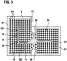
- the Figure 3 shows a cross section of a second embodiment of the temperature control device 3 according to the invention, arranged parallel to a longitudinal direction of the flow deflection unit.
- the temperature control device 3 shown according to a second embodiment differs from that in FIG Figure 2 temperature control device 3 shown in the design of the first area 19 of the flow space 4 and the second area 20 of the flow space 4.
- the cross-sectional area 28 in the first region 19 also has an asymmetrical shape.
- the first section 281 and the second section 282 are L-shaped to one another, with the transition area between the first Section 281 second section 282 in contrast to that in FIG Figure 2 shown first embodiment is not rounded.
- the second embodiment of a temperature control device differs from the first embodiment in that a maximum of four spacer elements 11 are arranged between the first side surface 17 of the flow deflection unit 15 in the first section 281 and the first housing wall 91 on the shortest connection and furthermore between of the second side surface 18 of the flow deflection unit 15 in the first section 281 and the second housing wall 92 on the shortest connection in each case a maximum of six spacer elements 11 are arranged.
- the second embodiment shown differs from the first embodiment in that only three spacer elements 11 instead of four spacer elements 11 are arranged between the first end 24 and the seventh housing wall 97.
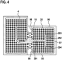
- the Figure 4 shows a cross section of a third embodiment of the temperature control device 3 according to the invention, arranged parallel to a longitudinal direction of the flow deflection unit.
- the one in the Figure 4 The third embodiment shown of a temperature control device 3 according to the invention differs from the first embodiment which is shown in FIG Figure 2 is shown in the formation of the second region 20 of the flow space 4.
- the current deflection unit 15 is T-shaped.
- the flow deflection unit 15 has a first section 291 and 291 in the second region 20 a second section 292.
- the second section 292 has a first end 293 and a second end 294.
- the current deflection unit 15 is designed in such a way that the axis of symmetry of the first section 291 and the axis of symmetry of the second section 292 are arranged perpendicular to one another, the axis of symmetry of the first section 291 being the axis of symmetry of the second section 292 between the first end 293 and the second end 294 cuts.
- a maximum of four spacer elements 11 are arranged between the second section 292 and the seventh housing wall 97 on the shortest connection. Furthermore, a maximum of three spacer elements 11 are arranged between the first end 293 and the sixth housing wall 96 on the shortest connection. Furthermore, a maximum of three spacer elements 11 are arranged between the second end 294 and the fifth housing wall 95 on the shortest connection.
- the in the Figures 2 to 4 have in common that between the first housing wall 91 and the second housing wall 92 on the shortest connection a maximum of eleven spacer elements 11 are arranged in each case. Furthermore, a maximum of eighteen spacer elements 11 are arranged between the third housing wall 93 and the fourth housing wall 94 on the shortest connection. Furthermore, a maximum of thirteen spacer elements 11 are arranged between the fifth housing wall 95 and the sixth housing wall 96 on the shortest connection. Between the seventh housing wall 97 and an eighth housing wall 98, a maximum of eleven spacer elements 11 are arranged on the shortest connection. This highest number of the arrangement of spacer elements 11 between two housing walls 9 is achieved when the current deflection unit 15 is not arranged to run between the respective housing wall 9.
- the Figure 5 shows a second temperature control body 6 in a perspective view, wherein the side facing away from the flow space 4 of the temperature control device 3 can be seen.
- the temperature control body 6 is designed in such a way that it encompasses the spacer elements 11 and the current deflection unit 15.
- the spacer elements 11, the flow deflection unit 15 protrude from the plane of the base body and are thus arranged within the flow space 4. Due to this design, the spacer elements 11 and the current deflection unit 15 can be seen as depressions on the second temperature control body 6.
- Such a design can be achieved, for example, by means of a roll cladding process.
- the Figure 5 the first connection 22 and the second connection 23, which serve to let in and discharge temperature control fluid into the flow space 4 and are arranged on the side of the second temperature control body 6 facing away from the flow space 4.
- the Figure 6 and the Figure 7 show the first connection 22 and the second connection 23 in a first perspective view and a second perspective view.
- the first connection 22 and the second connection 23 form a connection element 211 which is connected to a temperature control fluid leading to and into the Figures 6 and 7 line not shown can be connected.
- connection 22, and the second connection 23 have means 212 which are provided for connecting the respective connection 21, 22 to the second temperature control body 6. Furthermore, the connection 21, 22 has at least one recess 213 in which a seal (not shown) can be arranged.
- connection 22, 23 has ribs 214 arranged in a star shape, which increase the mechanical stability.
- first temperature control body 5 and the second temperature control body 6 While it is advantageous to connect the first temperature control body 5 and the second temperature control body 6, in particular with the formation of the spacer elements 11 and / or the current deflection unit 12, by means of a roll cladding process, it is advantageous to connect the first connection 22 and the second connection 23 by means of laser welding in to connect the second temperature control element 6.
- the spacer elements 11 advantageously have a diameter 261 of 15 mm or 16 mm, the isosceles triangles 27 advantageously a shortest side of 29 mm or 30 mm and the first surface 7 and the second surface 8 advantageously a distance 12 of 2 mm or 2.5 mm.
- the numerically determined pressure losses of a temperature control device 3 according to the invention could be reduced when a temperature control fluid flows through the flow space 4 from the first connection 21 to the second connection 23 at a volume flow of 500 l / h or 1200 l / h the flow of the temperature control fluid can be evenly distributed, while at the same time the temperature control device 3 has sufficient mechanical stability with respect to the load that occurs.
- a temperature control device 3 according to the Figure 2
- the first embodiment shown with a diameter 261 of 16 mm, with a shortest side of the isosceles triangle 27 of 30 mm and with a distance 12 of 2 mm showed overall the lowest pressure loss and the best distribution of the flowing temperature control fluid within the flow space 4 in a comparison of all simulated Flow spaces 4.
Landscapes
- Engineering & Computer Science (AREA)
- Manufacturing & Machinery (AREA)
- Chemical & Material Sciences (AREA)
- Chemical Kinetics & Catalysis (AREA)
- Electrochemistry (AREA)
- General Chemical & Material Sciences (AREA)
- Secondary Cells (AREA)
Claims (11)
- Module de batterie doté d'un dispositif d'équilibrage de température,comprenant un espace d'écoulement (4) substantiellement fermé qui présente une pluralité d'éléments d'écartement (11), dans lequelles éléments d'écartement (11) sont disposés à l'intérieur de l'espace d'écoulement (4), etle dispositif d'équilibrage de température (3) présente en outre une unité de déviation de flux (15) disposée à l'intérieur de l'espace d'écoulement (4)ayant une direction longitudinale (16) s'étendant le long de l'unité de déviation de flux (15) d'une première extrémité (24) à une deuxième extrémité (25) de l'unité de déviation de flux (15), dans lequell'unité de déviation de flux (15) réalise une première surface latérale (17) et une deuxième surface latérale (18)qui sont disposées le long de la direction longitudinale (16) sur des côtés opposés l'un à l'autre de l'unité de déviation de flux (15), la première surface latérale (17) et la deuxième surface latérale (18) étant disposées de manière directement adjacente au moins par endroits à un élément d'écartement (11, 111, 112), l'espace d'écoulement (4) réalisant une première zone (19) et une deuxième zone (20),dans lesquelles des éléments d'écartement (11) sont disposés respectivement, dans lequelentre la première zone (19) et la deuxième zone (20) de l'espace d'écoulement (4),un premier raccord (22) réalisé pour admettre un fluide d'équilibrage de température dans l'espace d'écoulement (4) et un deuxième raccord (23) réalisé pour évacuer un fluide d'équilibrage de température de l'espace d'écoulement (4) sont disposés,caractérisé en ce que sur une surface (13), détournée de l'espace d'écoulement (4), du dispositif d'équilibrage de température (3), au moins un élément de batterie (2) est disposé.
- Module de batterie selon la revendication 1,comprenant un premier corps d'équilibrage de température (5) ayant une première surface (7) et un deuxième corps d'équilibrage de température (6) ayant une deuxième surface (8) qui sont réalisés respectivement substantiellement à partir d'un corps de base planaire, dans lequella première surface (7) et la deuxième surface (8) du corps d'équilibrage de température (5, 6) sont espacées l'une de l'autre au moyen de la pluralité d'éléments d'écartement (11) en réalisant l'espace d'écoulement (4), en étant en particulier disposées en parallèle l'une à l'autre, dans lequelles éléments d'écartement (11) entrent respectivement en contact avec la première surface (7) et/ou la deuxième surface (8), en particulier en étant reliées respectivement à la première surface (7) et/ou à la deuxième surface (8).
- Module de batterie selon la revendication 2, caractérisé en ce que le premier corps d'équilibrage de température (5) et/ou le deuxième corps d'équilibrage de température (6) sont réalisés en matériau métallique, en particulier en aluminium, ou en matière plastique.
- Module de batterie selon l'une quelconque des revendications 2 et 3, caractérisé en ce que le premier corps d'équilibrage de température (5) et/ou le deuxième corps d'équilibrage de température (6) comprennent la pluralité des éléments d'écartement (11), les éléments d'écartement (11) faisant respectivement saillie à partir du plan du corps de base planaire du corps d'équilibrage de température (5, 6) .
- Module de batterie selon l'une quelconque des revendications précédentes, caractérisé en ce queles éléments d'écartement (11) sont disposés en structures régulières les uns par rapport aux autres, ettrois éléments d'écartement (11) directement voisins les uns aux autres forment respectivement un triangle isocèle (27), dans lequelun côté le plus court du triangle isocèle (27) présente de préférence une longueur comprise entre 20 mm et 40 mm, de plus grande préférence une longueur comprise entre 25 mm et 35 mm, et en particulier une longueur de 29 mm.
- Module de batterie selon l'une quelconque des revendications 2 à 5, caractérisé en ce queles éléments d'écartement (11) disposés à l'intérieur de l'espace d'écoulement (4) présentent dans un plan en parallèle à la première surface (7) et/ou à la deuxième surface (8) une superficie de la section (26) circulaire, carrée, ronde, ovale, elliptique ou rectangulaire, dans lequelen particulier une superficie de la section circulaire (26) présente de préférence un diamètre (261) de 10 mm à 20 mm et de plus grande préférence un diamètre (261) de 15 mm à 17 mm.
- Module de batterie selon l'une quelconque des revendications 2 à 6, caractérisé en ce qu'une superficie de la section parallèle à la première surface (7) et/ou à la deuxième surface (8) de l'unité de déviation de flux (4) présente une forme asymétrique, dans lequel
en particulier les superficies de la section (28, 29) présentent une forme différente dans la première zone (19) et la deuxième zone (20). - Module de batterie selon la revendication 7, caractériséen ce que la superficie de la section (28) présente dans la première zone (19) une première partie (281) et une deuxième partie (282) qui sont disposées en forme de L l'une par rapport à l'autre, en étant en particulier disposées en forme de L arrondie, et/ouen ce que la superficie de la section (29) dans la deuxième zone (20) présente au moins une première partie (29, 291) qui est réalisée en forme I, et présente de plus grande préférence en particulier une deuxième partie (292), et la première partie (291) et la deuxième partie (292) sont disposées en forme de T l'une par rapport à l'autre.
- Module de batterie selon l'une quelconque des revendications 2 à 8, caractérisé en ce que la première surface (7) du premier élément d'équilibrage de température (5) et la deuxième surface (8) du deuxième élément d'équilibrage de température (6) présentent un écartement (12) de préférence de 1 mm à 5 mm, de plus grande préférence de 2 mm à 3 mm, et en particulier un écartement (12) de 2,5 mm.
- Module de batterie selon l'une quelconque des revendications précédentes, caractérisé en ce que la surface (13), détournée de l'espace d'écoulement (4), du dispositif d'équilibrage de température (3) est réalisée de manière plane.
- Procédé de fabrication d'un module de batterie selon l'une quelconque des revendications 1 à 10, dans lequeldans une première étape, les éléments d'écartement (11) sont disposés sur un corps d'équilibrage de température (5, 6), ou un corps d'équilibrage de température (5, 6) est réalisé de telle sorte qu'il comprend les éléments d'écartement (11),dans une deuxième étape, l'unité de déviation de flux (15) est disposée sur l'un des corps d'équilibrage de température (5, 6), ou un corps d'équilibrage de température (5, 6) est réalisé de telle sorte qu'il comprend l'unité de déviation de flux (15), dans lequell'unité de déviation de flux (15) présente une direction longitudinale (16) s'étendant le long de l'unité de déviation de flux (15) d'une première extrémité (24) à une deuxième extrémité (25) de l'unité de déviation de flux (15), et l'unité de déviation de flux (15) réalise une première surface latérale (17) et une deuxième surface latérale (18) qui sont disposées le long de la direction longitudinale (16) sur des côtés opposés l'un à l'autre de l'unité de déviation de flux (15),dans une troisième étape, le premier corps d'équilibrage de température (5) et le deuxième corps d'équilibrage de température (6) sont reliés l'un à l'autre en réalisant un espace d'écoulement (4) substantiellement fermé de sorte que l'unité de déviation de flux (15) est disposée à l'intérieur de l'espace d'écoulement (4), et la première surface latérale (17) et la deuxième surface latérale (18) sont disposées de manière directement adjacente au moins par endroits à un élément d'écartement (11, 111, 112),le processus de raccordement étant réalisé en particulier sous la forme d'un processus de placage par laminage, au moins un élément de batterie (2) étant disposé sur une surface (13), détournée de l'espace d'écoulement (4), du dispositif d'équilibrage de température (3).
Applications Claiming Priority (2)
| Application Number | Priority Date | Filing Date | Title |
|---|---|---|---|
| DE102016205237.3A DE102016205237A1 (de) | 2016-03-30 | 2016-03-30 | Temperiervorrichtung eines Batteriemoduls, Verfahren zu dessen Herstellung und Batteriemodul |
| PCT/EP2017/055549 WO2017167563A1 (fr) | 2016-03-30 | 2017-03-09 | Dispositif d'équilibrage de température d'un module de batterie, son procédé de fabrication et module de batterie |
Publications (2)
| Publication Number | Publication Date |
|---|---|
| EP3437155A1 EP3437155A1 (fr) | 2019-02-06 |
| EP3437155B1 true EP3437155B1 (fr) | 2021-11-10 |
Family
ID=58264540
Family Applications (1)
| Application Number | Title | Priority Date | Filing Date |
|---|---|---|---|
| EP17709679.9A Active EP3437155B1 (fr) | 2016-03-30 | 2017-03-09 | Dispositif d'echange de chaleur pour module de batteries, procédé de production de celui et module de batteries |
Country Status (5)
| Country | Link |
|---|---|
| US (1) | US10797366B2 (fr) |
| EP (1) | EP3437155B1 (fr) |
| CN (1) | CN108886188B (fr) |
| DE (1) | DE102016205237A1 (fr) |
| WO (1) | WO2017167563A1 (fr) |
Families Citing this family (13)
| Publication number | Priority date | Publication date | Assignee | Title |
|---|---|---|---|---|
| USD868692S1 (en) * | 2018-02-05 | 2019-12-03 | Xos, Inc. | Battery module |
| AT520929B1 (de) * | 2018-06-08 | 2019-09-15 | Raiffeisenlandesbank Oberoesterreich Ag | Temperiervorrichtung für einzelne, zu einem Modul zusammengesetzte Batteriezellen |
| JP6783836B2 (ja) * | 2018-09-19 | 2020-11-11 | 株式会社前川製作所 | プレート重合体及び熱交換器 |
| DE102018220937A1 (de) * | 2018-12-04 | 2020-06-04 | Robert Bosch Gmbh | Batteriemodul |
| KR102845719B1 (ko) * | 2019-06-10 | 2025-08-12 | 현대자동차주식회사 | 배터리 모듈용 냉각블록 및 그 제조방법 |
| AT522356B1 (de) * | 2019-08-28 | 2020-10-15 | Kreisel Electric Gmbh & Co Kg | Temperiervorrichtung |
| DE102019214199A1 (de) * | 2019-09-18 | 2021-03-18 | Robert Bosch Gmbh | Batterie und Verwendung einer solchen Batterie |
| DE102021200040A1 (de) * | 2021-01-05 | 2022-07-07 | Robert Bosch Gesellschaft mit beschränkter Haftung | Temperierungsvorrichtung für ein Batteriemodul, Herstellungsverfahren und Temperierungsverfahren |
| KR102852584B1 (ko) * | 2021-03-05 | 2025-08-28 | 주식회사 엘지에너지솔루션 | 전지 팩 및 이를 포함하는 디바이스 |
| DE102021209308A1 (de) * | 2021-08-25 | 2023-03-02 | Robert Bosch Gesellschaft mit beschränkter Haftung | Kühlvorrichtung zur Kühlung einer Leistungselektronik eines Batteriesystems und Batteriesystem |
| DE102021122913A1 (de) | 2021-09-03 | 2023-03-09 | Muhr Und Bender Kg | Batteriekühlvorrichtung für ein elektrisches Batteriemodul eines Elektroantriebs |
| DE102022128913B3 (de) | 2022-11-02 | 2024-02-01 | Dr. Ing. H.C. F. Porsche Aktiengesellschaft | Vorrichtung zum Kühlen einer Batterie, Verfahren zum Herstellen der Vorrichtung, Batterie und Fahrzeug umfassend die Vorrichtung |
| DE102023116022A1 (de) * | 2023-06-20 | 2024-12-24 | Dr. Ing. H.C. F. Porsche Aktiengesellschaft | Batteriemodul |
Citations (1)
| Publication number | Priority date | Publication date | Assignee | Title |
|---|---|---|---|---|
| US20140216702A1 (en) * | 2011-07-25 | 2014-08-07 | Valeo Systemes Thermiques | Heat-Exchanger Plate |
Family Cites Families (11)
| Publication number | Priority date | Publication date | Assignee | Title |
|---|---|---|---|---|
| FR2774215B1 (fr) * | 1998-01-29 | 2000-02-25 | Alsthom Cge Alcatel | Batterie monobloc etanche munie d'un dispositif de refroidissement |
| EP3026753A1 (fr) | 2010-11-10 | 2016-06-01 | Valeo Systemes Thermiques | Dispositif de refroidissement de véhicule, ensemble de refroidissement de batterie de commande de véhicule et procédé de fabrication d'un dispositif de refroidissement de véhicule |
| DE202012102349U1 (de) * | 2011-07-14 | 2012-07-18 | Visteon Global Technologies, Inc. | Batteriekühler |
| US8940425B2 (en) | 2012-01-24 | 2015-01-27 | GM Global Technology Operations LLC | Plastic liquid heat exchanger for battery cooling system |
| KR20140026961A (ko) * | 2012-08-24 | 2014-03-06 | 주식회사 한국쿨러 | 배터리용 열교환기 |
| DE102013219517A1 (de) * | 2012-09-28 | 2014-04-03 | Behr Gmbh & Co. Kg | Wärmeübertrager |
| DE102012023316A1 (de) | 2012-11-28 | 2014-05-28 | Li-Tec Battery Gmbh | Batterie mit einer Temperiereinrichtung |
| US9196935B2 (en) | 2013-03-12 | 2015-11-24 | Gm Global Technology Operations, Llc | Micro-channel cooling fin design based on an equivalent temperature gradient |
| DE102013216523B4 (de) | 2013-08-21 | 2026-01-22 | Mahle International Gmbh | Plattenwärmeübertrager |
| DE102014217546A1 (de) | 2014-09-03 | 2016-03-03 | Robert Bosch Gmbh | Kühl- und/oder Heizvorrichtung eines Batteriemoduls |
| CN104733806B (zh) * | 2015-03-13 | 2017-06-06 | 纳百川控股有限公司 | 电动汽车换热器 |
-
2016
- 2016-03-30 DE DE102016205237.3A patent/DE102016205237A1/de not_active Withdrawn
-
2017
- 2017-03-09 US US16/090,322 patent/US10797366B2/en active Active
- 2017-03-09 WO PCT/EP2017/055549 patent/WO2017167563A1/fr not_active Ceased
- 2017-03-09 CN CN201780021955.7A patent/CN108886188B/zh active Active
- 2017-03-09 EP EP17709679.9A patent/EP3437155B1/fr active Active
Patent Citations (1)
| Publication number | Priority date | Publication date | Assignee | Title |
|---|---|---|---|---|
| US20140216702A1 (en) * | 2011-07-25 | 2014-08-07 | Valeo Systemes Thermiques | Heat-Exchanger Plate |
Also Published As
| Publication number | Publication date |
|---|---|
| CN108886188B (zh) | 2022-05-27 |
| CN108886188A (zh) | 2018-11-23 |
| US20190115641A1 (en) | 2019-04-18 |
| DE102016205237A1 (de) | 2017-10-05 |
| WO2017167563A1 (fr) | 2017-10-05 |
| EP3437155A1 (fr) | 2019-02-06 |
| US10797366B2 (en) | 2020-10-06 |
Similar Documents
| Publication | Publication Date | Title |
|---|---|---|
| EP3437155B1 (fr) | Dispositif d'echange de chaleur pour module de batteries, procédé de production de celui et module de batteries | |
| EP2497145B1 (fr) | Dispositif accumulateur d'énergie | |
| EP2575418B1 (fr) | Refroidisseur électronique et procédé destiné à la fabrication d'un refroidisseur électronique | |
| EP1830426B1 (fr) | Plaque bipolaire, en particulier pour un empilement de cellules de combustible d'un véhicule automobile | |
| DE102010051106B4 (de) | Vorrichtung zum Kühlen eines Energiespeichermoduls eines Fahrzeugs | |
| DE112008002991B4 (de) | Brennstoffzelle und Gasseparataor für Brennstoffzelle | |
| DE102013216523B4 (de) | Plattenwärmeübertrager | |
| DE112016004919T5 (de) | Strukturelles Stützelement in Wärmetauschern | |
| DE112018002536T5 (de) | Gegenstrom-wärmetauscher mit seitlichen einlassarmaturen | |
| DE112012001293T5 (de) | Batteriezellenkühler | |
| EP3664180A1 (fr) | Module de batterie | |
| DE102008056900A1 (de) | Bipolarplatte für eine Brennstoffzellenanordnung, insbesondere zur Anordnung zwischen zwei benachbarten Membran-Elektroden-Anordnungen in einem Brennstoffzellenstapel | |
| DE102012218082A1 (de) | Trägerelement für eine elektrische Energiespeicherzelle mit Kühlkanälen mit einem nicht kreisförmigen Querschnitt, elektrischer Energiespeicher und Herstellverfahren für ein Trägerelement | |
| DE102016210138A1 (de) | Temperiervorrichtung eines Batteriemoduls und Batteriemodul | |
| DE102012205750A1 (de) | Kühleinrichtung für einen elektronischen Energiespeicher, Kühlmittelverteiler für eine Mehrzahl von Kühleinrichtungen, Kühlsystem und Energiespeicher mit einem Kühlsystem | |
| DE102011080974B4 (de) | Batterie und Kraftfahrzeug | |
| DE202017102436U1 (de) | Wärmetauscher mit Mikrokanal-Struktur oder Flügelrohr-Struktur | |
| DE102021202709A1 (de) | Batteriemodul und Verfahren zur Herstellung eines Batteriemoduls | |
| DE102012207995A1 (de) | Kühleinrichtung sowie Energiespeicher mit einer Kühleinrichtung | |
| EP2355232B1 (fr) | Caloporteur pour un module de conduction thermique | |
| DE102020000274A1 (de) | Verfahren zur Herstellung eines Rippen-Platten-Wärmetauschers | |
| DE102019209155A1 (de) | Energiespeicheranordnung | |
| DE102019128143A1 (de) | Temperier- und Abstützeinrichtung für ein Batteriemodul, Batteriemodul sowie Batterie | |
| DE102019207136A1 (de) | Kühler für eine Batterie, Verwendung von Kunststoffröhren in einem Kühler und Batterie mit zumindest einem Kühler | |
| DE102013219517A1 (de) | Wärmeübertrager |
Legal Events
| Date | Code | Title | Description |
|---|---|---|---|
| STAA | Information on the status of an ep patent application or granted ep patent |
Free format text: STATUS: UNKNOWN |
|
| STAA | Information on the status of an ep patent application or granted ep patent |
Free format text: STATUS: THE INTERNATIONAL PUBLICATION HAS BEEN MADE |
|
| PUAI | Public reference made under article 153(3) epc to a published international application that has entered the european phase |
Free format text: ORIGINAL CODE: 0009012 |
|
| STAA | Information on the status of an ep patent application or granted ep patent |
Free format text: STATUS: REQUEST FOR EXAMINATION WAS MADE |
|
| 17P | Request for examination filed |
Effective date: 20181030 |
|
| AK | Designated contracting states |
Kind code of ref document: A1 Designated state(s): AL AT BE BG CH CY CZ DE DK EE ES FI FR GB GR HR HU IE IS IT LI LT LU LV MC MK MT NL NO PL PT RO RS SE SI SK SM TR |
|
| AX | Request for extension of the european patent |
Extension state: BA ME |
|
| DAV | Request for validation of the european patent (deleted) | ||
| DAX | Request for extension of the european patent (deleted) | ||
| TPAC | Observations filed by third parties |
Free format text: ORIGINAL CODE: EPIDOSNTIPA |
|
| STAA | Information on the status of an ep patent application or granted ep patent |
Free format text: STATUS: EXAMINATION IS IN PROGRESS |
|
| 17Q | First examination report despatched |
Effective date: 20200203 |
|
| RAP1 | Party data changed (applicant data changed or rights of an application transferred) |
Owner name: ROBERT BOSCH GMBH |
|
| GRAP | Despatch of communication of intention to grant a patent |
Free format text: ORIGINAL CODE: EPIDOSNIGR1 |
|
| STAA | Information on the status of an ep patent application or granted ep patent |
Free format text: STATUS: GRANT OF PATENT IS INTENDED |
|
| INTG | Intention to grant announced |
Effective date: 20210601 |
|
| GRAS | Grant fee paid |
Free format text: ORIGINAL CODE: EPIDOSNIGR3 |
|
| GRAA | (expected) grant |
Free format text: ORIGINAL CODE: 0009210 |
|
| STAA | Information on the status of an ep patent application or granted ep patent |
Free format text: STATUS: THE PATENT HAS BEEN GRANTED |
|
| AK | Designated contracting states |
Kind code of ref document: B1 Designated state(s): AL AT BE BG CH CY CZ DE DK EE ES FI FR GB GR HR HU IE IS IT LI LT LU LV MC MK MT NL NO PL PT RO RS SE SI SK SM TR |
|
| REG | Reference to a national code |
Ref country code: GB Ref legal event code: FG4D Free format text: NOT ENGLISH |
|
| REG | Reference to a national code |
Ref country code: AT Ref legal event code: REF Ref document number: 1446916 Country of ref document: AT Kind code of ref document: T Effective date: 20211115 Ref country code: CH Ref legal event code: EP |
|
| REG | Reference to a national code |
Ref country code: DE Ref legal event code: R096 Ref document number: 502017011965 Country of ref document: DE |
|
| REG | Reference to a national code |
Ref country code: IE Ref legal event code: FG4D Free format text: LANGUAGE OF EP DOCUMENT: GERMAN |
|
| REG | Reference to a national code |
Ref country code: LT Ref legal event code: MG9D |
|
| REG | Reference to a national code |
Ref country code: NL Ref legal event code: MP Effective date: 20211110 |
|
| PG25 | Lapsed in a contracting state [announced via postgrant information from national office to epo] |
Ref country code: RS Free format text: LAPSE BECAUSE OF FAILURE TO SUBMIT A TRANSLATION OF THE DESCRIPTION OR TO PAY THE FEE WITHIN THE PRESCRIBED TIME-LIMIT Effective date: 20211110 Ref country code: LT Free format text: LAPSE BECAUSE OF FAILURE TO SUBMIT A TRANSLATION OF THE DESCRIPTION OR TO PAY THE FEE WITHIN THE PRESCRIBED TIME-LIMIT Effective date: 20211110 Ref country code: FI Free format text: LAPSE BECAUSE OF FAILURE TO SUBMIT A TRANSLATION OF THE DESCRIPTION OR TO PAY THE FEE WITHIN THE PRESCRIBED TIME-LIMIT Effective date: 20211110 Ref country code: BG Free format text: LAPSE BECAUSE OF FAILURE TO SUBMIT A TRANSLATION OF THE DESCRIPTION OR TO PAY THE FEE WITHIN THE PRESCRIBED TIME-LIMIT Effective date: 20220210 |
|
| PG25 | Lapsed in a contracting state [announced via postgrant information from national office to epo] |
Ref country code: IS Free format text: LAPSE BECAUSE OF FAILURE TO SUBMIT A TRANSLATION OF THE DESCRIPTION OR TO PAY THE FEE WITHIN THE PRESCRIBED TIME-LIMIT Effective date: 20220310 Ref country code: SE Free format text: LAPSE BECAUSE OF FAILURE TO SUBMIT A TRANSLATION OF THE DESCRIPTION OR TO PAY THE FEE WITHIN THE PRESCRIBED TIME-LIMIT Effective date: 20211110 Ref country code: PT Free format text: LAPSE BECAUSE OF FAILURE TO SUBMIT A TRANSLATION OF THE DESCRIPTION OR TO PAY THE FEE WITHIN THE PRESCRIBED TIME-LIMIT Effective date: 20220310 Ref country code: PL Free format text: LAPSE BECAUSE OF FAILURE TO SUBMIT A TRANSLATION OF THE DESCRIPTION OR TO PAY THE FEE WITHIN THE PRESCRIBED TIME-LIMIT Effective date: 20211110 Ref country code: NO Free format text: LAPSE BECAUSE OF FAILURE TO SUBMIT A TRANSLATION OF THE DESCRIPTION OR TO PAY THE FEE WITHIN THE PRESCRIBED TIME-LIMIT Effective date: 20220210 Ref country code: NL Free format text: LAPSE BECAUSE OF FAILURE TO SUBMIT A TRANSLATION OF THE DESCRIPTION OR TO PAY THE FEE WITHIN THE PRESCRIBED TIME-LIMIT Effective date: 20211110 Ref country code: LV Free format text: LAPSE BECAUSE OF FAILURE TO SUBMIT A TRANSLATION OF THE DESCRIPTION OR TO PAY THE FEE WITHIN THE PRESCRIBED TIME-LIMIT Effective date: 20211110 Ref country code: HR Free format text: LAPSE BECAUSE OF FAILURE TO SUBMIT A TRANSLATION OF THE DESCRIPTION OR TO PAY THE FEE WITHIN THE PRESCRIBED TIME-LIMIT Effective date: 20211110 Ref country code: GR Free format text: LAPSE BECAUSE OF FAILURE TO SUBMIT A TRANSLATION OF THE DESCRIPTION OR TO PAY THE FEE WITHIN THE PRESCRIBED TIME-LIMIT Effective date: 20220211 Ref country code: ES Free format text: LAPSE BECAUSE OF FAILURE TO SUBMIT A TRANSLATION OF THE DESCRIPTION OR TO PAY THE FEE WITHIN THE PRESCRIBED TIME-LIMIT Effective date: 20211110 |
|
| PG25 | Lapsed in a contracting state [announced via postgrant information from national office to epo] |
Ref country code: SM Free format text: LAPSE BECAUSE OF FAILURE TO SUBMIT A TRANSLATION OF THE DESCRIPTION OR TO PAY THE FEE WITHIN THE PRESCRIBED TIME-LIMIT Effective date: 20211110 Ref country code: SK Free format text: LAPSE BECAUSE OF FAILURE TO SUBMIT A TRANSLATION OF THE DESCRIPTION OR TO PAY THE FEE WITHIN THE PRESCRIBED TIME-LIMIT Effective date: 20211110 Ref country code: RO Free format text: LAPSE BECAUSE OF FAILURE TO SUBMIT A TRANSLATION OF THE DESCRIPTION OR TO PAY THE FEE WITHIN THE PRESCRIBED TIME-LIMIT Effective date: 20211110 Ref country code: EE Free format text: LAPSE BECAUSE OF FAILURE TO SUBMIT A TRANSLATION OF THE DESCRIPTION OR TO PAY THE FEE WITHIN THE PRESCRIBED TIME-LIMIT Effective date: 20211110 Ref country code: DK Free format text: LAPSE BECAUSE OF FAILURE TO SUBMIT A TRANSLATION OF THE DESCRIPTION OR TO PAY THE FEE WITHIN THE PRESCRIBED TIME-LIMIT Effective date: 20211110 Ref country code: CZ Free format text: LAPSE BECAUSE OF FAILURE TO SUBMIT A TRANSLATION OF THE DESCRIPTION OR TO PAY THE FEE WITHIN THE PRESCRIBED TIME-LIMIT Effective date: 20211110 |
|
| REG | Reference to a national code |
Ref country code: DE Ref legal event code: R097 Ref document number: 502017011965 Country of ref document: DE |
|
| PLBE | No opposition filed within time limit |
Free format text: ORIGINAL CODE: 0009261 |
|
| STAA | Information on the status of an ep patent application or granted ep patent |
Free format text: STATUS: NO OPPOSITION FILED WITHIN TIME LIMIT |
|
| 26N | No opposition filed |
Effective date: 20220811 |
|
| PG25 | Lapsed in a contracting state [announced via postgrant information from national office to epo] |
Ref country code: MC Free format text: LAPSE BECAUSE OF FAILURE TO SUBMIT A TRANSLATION OF THE DESCRIPTION OR TO PAY THE FEE WITHIN THE PRESCRIBED TIME-LIMIT Effective date: 20211110 Ref country code: AL Free format text: LAPSE BECAUSE OF FAILURE TO SUBMIT A TRANSLATION OF THE DESCRIPTION OR TO PAY THE FEE WITHIN THE PRESCRIBED TIME-LIMIT Effective date: 20211110 |
|
| REG | Reference to a national code |
Ref country code: CH Ref legal event code: PL |
|
| GBPC | Gb: european patent ceased through non-payment of renewal fee |
Effective date: 20220309 |
|
| PG25 | Lapsed in a contracting state [announced via postgrant information from national office to epo] |
Ref country code: SI Free format text: LAPSE BECAUSE OF FAILURE TO SUBMIT A TRANSLATION OF THE DESCRIPTION OR TO PAY THE FEE WITHIN THE PRESCRIBED TIME-LIMIT Effective date: 20211110 |
|
| REG | Reference to a national code |
Ref country code: BE Ref legal event code: MM Effective date: 20220331 |
|
| PG25 | Lapsed in a contracting state [announced via postgrant information from national office to epo] |
Ref country code: LU Free format text: LAPSE BECAUSE OF NON-PAYMENT OF DUE FEES Effective date: 20220309 Ref country code: LI Free format text: LAPSE BECAUSE OF NON-PAYMENT OF DUE FEES Effective date: 20220331 Ref country code: IE Free format text: LAPSE BECAUSE OF NON-PAYMENT OF DUE FEES Effective date: 20220309 Ref country code: GB Free format text: LAPSE BECAUSE OF NON-PAYMENT OF DUE FEES Effective date: 20220309 Ref country code: CH Free format text: LAPSE BECAUSE OF NON-PAYMENT OF DUE FEES Effective date: 20220331 |
|
| PG25 | Lapsed in a contracting state [announced via postgrant information from national office to epo] |
Ref country code: BE Free format text: LAPSE BECAUSE OF NON-PAYMENT OF DUE FEES Effective date: 20220331 |
|
| REG | Reference to a national code |
Ref country code: AT Ref legal event code: MM01 Ref document number: 1446916 Country of ref document: AT Kind code of ref document: T Effective date: 20220309 |
|
| PG25 | Lapsed in a contracting state [announced via postgrant information from national office to epo] |
Ref country code: IT Free format text: LAPSE BECAUSE OF FAILURE TO SUBMIT A TRANSLATION OF THE DESCRIPTION OR TO PAY THE FEE WITHIN THE PRESCRIBED TIME-LIMIT Effective date: 20211110 |
|
| PG25 | Lapsed in a contracting state [announced via postgrant information from national office to epo] |
Ref country code: AT Free format text: LAPSE BECAUSE OF NON-PAYMENT OF DUE FEES Effective date: 20220309 |
|
| PG25 | Lapsed in a contracting state [announced via postgrant information from national office to epo] |
Ref country code: HU Free format text: LAPSE BECAUSE OF FAILURE TO SUBMIT A TRANSLATION OF THE DESCRIPTION OR TO PAY THE FEE WITHIN THE PRESCRIBED TIME-LIMIT; INVALID AB INITIO Effective date: 20170309 |
|
| PG25 | Lapsed in a contracting state [announced via postgrant information from national office to epo] |
Ref country code: MK Free format text: LAPSE BECAUSE OF FAILURE TO SUBMIT A TRANSLATION OF THE DESCRIPTION OR TO PAY THE FEE WITHIN THE PRESCRIBED TIME-LIMIT Effective date: 20211110 Ref country code: CY Free format text: LAPSE BECAUSE OF FAILURE TO SUBMIT A TRANSLATION OF THE DESCRIPTION OR TO PAY THE FEE WITHIN THE PRESCRIBED TIME-LIMIT Effective date: 20211110 |
|
| PG25 | Lapsed in a contracting state [announced via postgrant information from national office to epo] |
Ref country code: TR Free format text: LAPSE BECAUSE OF FAILURE TO SUBMIT A TRANSLATION OF THE DESCRIPTION OR TO PAY THE FEE WITHIN THE PRESCRIBED TIME-LIMIT Effective date: 20211110 |
|
| PG25 | Lapsed in a contracting state [announced via postgrant information from national office to epo] |
Ref country code: MT Free format text: LAPSE BECAUSE OF FAILURE TO SUBMIT A TRANSLATION OF THE DESCRIPTION OR TO PAY THE FEE WITHIN THE PRESCRIBED TIME-LIMIT Effective date: 20211110 |
|
| PGFP | Annual fee paid to national office [announced via postgrant information from national office to epo] |
Ref country code: DE Payment date: 20250522 Year of fee payment: 9 |
|
| PGFP | Annual fee paid to national office [announced via postgrant information from national office to epo] |
Ref country code: FR Payment date: 20260325 Year of fee payment: 10 |