EP3437170B1 - Hybridenergiespeichermodule für pulsleistungseffektoren mit mittelspannungsgleichstrom (mvdc)-leistungsverteilung - Google Patents
Hybridenergiespeichermodule für pulsleistungseffektoren mit mittelspannungsgleichstrom (mvdc)-leistungsverteilung Download PDFInfo
- Publication number
- EP3437170B1 EP3437170B1 EP17787271.0A EP17787271A EP3437170B1 EP 3437170 B1 EP3437170 B1 EP 3437170B1 EP 17787271 A EP17787271 A EP 17787271A EP 3437170 B1 EP3437170 B1 EP 3437170B1
- Authority
- EP
- European Patent Office
- Prior art keywords
- power
- electrical machine
- rotating electrical
- mvdc
- energy storage
- Prior art date
- Legal status (The legal status is an assumption and is not a legal conclusion. Google has not performed a legal analysis and makes no representation as to the accuracy of the status listed.)
- Active
Links
Images



Classifications
-
- H—ELECTRICITY
- H02—GENERATION; CONVERSION OR DISTRIBUTION OF ELECTRIC POWER
- H02J—ELECTRIC POWER NETWORKS; CIRCUIT ARRANGEMENTS OR SYSTEMS FOR SUPPLYING OR DISTRIBUTING ELECTRIC POWER; SYSTEMS FOR STORING ELECTRIC ENERGY
- H02J3/00—Circuit arrangements for AC mains or AC distribution networks
- H02J3/28—Arrangements for balancing of the load in networks by storage of energy
- H02J3/30—Arrangements for balancing of the load in networks by storage of energy using dynamo-electric machines coupled to flywheels
-
- H—ELECTRICITY
- H02—GENERATION; CONVERSION OR DISTRIBUTION OF ELECTRIC POWER
- H02J—ELECTRIC POWER NETWORKS; CIRCUIT ARRANGEMENTS OR SYSTEMS FOR SUPPLYING OR DISTRIBUTING ELECTRIC POWER; SYSTEMS FOR STORING ELECTRIC ENERGY
- H02J3/00—Circuit arrangements for AC mains or AC distribution networks
- H02J3/28—Arrangements for balancing of the load in networks by storage of energy
- H02J3/32—Arrangements for balancing of the load in networks by storage of energy using batteries or super capacitors with converting means
-
- H—ELECTRICITY
- H02—GENERATION; CONVERSION OR DISTRIBUTION OF ELECTRIC POWER
- H02J—ELECTRIC POWER NETWORKS; CIRCUIT ARRANGEMENTS OR SYSTEMS FOR SUPPLYING OR DISTRIBUTING ELECTRIC POWER; SYSTEMS FOR STORING ELECTRIC ENERGY
- H02J3/00—Circuit arrangements for AC mains or AC distribution networks
- H02J3/38—Arrangements for feeding a single network from two or more generators or sources in parallel; Arrangements for feeding already energised networks from additional generators or sources in parallel
- H02J3/381—Dispersed generators
-
- H—ELECTRICITY
- H02—GENERATION; CONVERSION OR DISTRIBUTION OF ELECTRIC POWER
- H02J—ELECTRIC POWER NETWORKS; CIRCUIT ARRANGEMENTS OR SYSTEMS FOR SUPPLYING OR DISTRIBUTING ELECTRIC POWER; SYSTEMS FOR STORING ELECTRIC ENERGY
- H02J7/00—Circuit arrangements for charging or discharging batteries or for supplying loads from batteries
- H02J7/14—Circuit arrangements for charging or discharging batteries or for supplying loads from batteries for charging batteries from dynamo-electric generators driven at varying speed, e.g. on vehicle
- H02J7/1423—Circuit arrangements for charging or discharging batteries or for supplying loads from batteries for charging batteries from dynamo-electric generators driven at varying speed, e.g. on vehicle with multiple batteries
-
- H—ELECTRICITY
- H02—GENERATION; CONVERSION OR DISTRIBUTION OF ELECTRIC POWER
- H02J—ELECTRIC POWER NETWORKS; CIRCUIT ARRANGEMENTS OR SYSTEMS FOR SUPPLYING OR DISTRIBUTING ELECTRIC POWER; SYSTEMS FOR STORING ELECTRIC ENERGY
- H02J7/00—Circuit arrangements for charging or discharging batteries or for supplying loads from batteries
- H02J7/865—Battery or charger load switching, e.g. concurrent charging and load supply
-
- H—ELECTRICITY
- H02—GENERATION; CONVERSION OR DISTRIBUTION OF ELECTRIC POWER
- H02K—DYNAMO-ELECTRIC MACHINES
- H02K7/00—Arrangements for handling mechanical energy structurally associated with dynamo-electric machines, e.g. structural association with mechanical driving motors or auxiliary dynamo-electric machines
- H02K7/02—Additional mass for increasing inertia, e.g. flywheels
- H02K7/025—Additional mass for increasing inertia, e.g. flywheels for power storage
-
- H—ELECTRICITY
- H03—ELECTRONIC CIRCUITRY
- H03K—PULSE TECHNIQUE
- H03K3/00—Circuits for generating electric pulses; Monostable, bistable or multistable circuits
- H03K3/02—Generators characterised by the type of circuit or by the means used for producing pulses
- H03K3/53—Generators characterised by the type of circuit or by the means used for producing pulses by the use of an energy-accumulating element discharged through the load by a switching device controlled by an external signal and not incorporating positive feedback
- H03K3/57—Generators characterised by the type of circuit or by the means used for producing pulses by the use of an energy-accumulating element discharged through the load by a switching device controlled by an external signal and not incorporating positive feedback the switching device being a semiconductor device
-
- H—ELECTRICITY
- H02—GENERATION; CONVERSION OR DISTRIBUTION OF ELECTRIC POWER
- H02J—ELECTRIC POWER NETWORKS; CIRCUIT ARRANGEMENTS OR SYSTEMS FOR SUPPLYING OR DISTRIBUTING ELECTRIC POWER; SYSTEMS FOR STORING ELECTRIC ENERGY
- H02J2105/00—Networks for supplying or distributing electric power characterised by their spatial reach or by the load
- H02J2105/30—Networks for supplying or distributing electric power characterised by their spatial reach or by the load the load networks being external to vehicles, i.e. exchanging power with vehicles
- H02J2105/31—Networks for supplying or distributing electric power characterised by their spatial reach or by the load the load networks being external to vehicles, i.e. exchanging power with vehicles for ships or vessels
-
- H—ELECTRICITY
- H02—GENERATION; CONVERSION OR DISTRIBUTION OF ELECTRIC POWER
- H02J—ELECTRIC POWER NETWORKS; CIRCUIT ARRANGEMENTS OR SYSTEMS FOR SUPPLYING OR DISTRIBUTING ELECTRIC POWER; SYSTEMS FOR STORING ELECTRIC ENERGY
- H02J7/00—Circuit arrangements for charging or discharging batteries or for supplying loads from batteries
- H02J7/34—Parallel operation in networks using both storage and other DC sources, e.g. providing buffering
- H02J7/345—Parallel operation in networks using both storage and other DC sources, e.g. providing buffering using capacitors as storage or buffering devices
-
- H—ELECTRICITY
- H02—GENERATION; CONVERSION OR DISTRIBUTION OF ELECTRIC POWER
- H02P—CONTROL OR REGULATION OF ELECTRIC MOTORS, ELECTRIC GENERATORS OR DYNAMO-ELECTRIC CONVERTERS; CONTROLLING TRANSFORMERS, REACTORS OR CHOKE COILS
- H02P25/00—Arrangements or methods for the control of AC motors characterised by the kind of AC motor or by structural details
- H02P25/16—Arrangements or methods for the control of AC motors characterised by the kind of AC motor or by structural details characterised by the circuit arrangement or by the kind of wiring
- H02P25/22—Multiple windings; Windings for more than three phases
-
- Y—GENERAL TAGGING OF NEW TECHNOLOGICAL DEVELOPMENTS; GENERAL TAGGING OF CROSS-SECTIONAL TECHNOLOGIES SPANNING OVER SEVERAL SECTIONS OF THE IPC; TECHNICAL SUBJECTS COVERED BY FORMER USPC CROSS-REFERENCE ART COLLECTIONS [XRACs] AND DIGESTS
- Y02—TECHNOLOGIES OR APPLICATIONS FOR MITIGATION OR ADAPTATION AGAINST CLIMATE CHANGE
- Y02E—REDUCTION OF GREENHOUSE GAS [GHG] EMISSIONS, RELATED TO ENERGY GENERATION, TRANSMISSION OR DISTRIBUTION
- Y02E60/00—Enabling technologies; Technologies with a potential or indirect contribution to GHG emissions mitigation
- Y02E60/16—Mechanical energy storage, e.g. flywheels or pressurised fluids
Definitions
- This disclosure is generally related to power systems. More specifically, this disclosure is directed to hybrid energy storage modules for pulsed power effectors with medium voltage direct current (MVDC) power distribution.
- MVDC medium voltage direct current
- Hybrid energy storage modules are being developed to support the storage and control of large amounts of electrical energy and to allow variable charging and discharging rates of that electrical energy. These types of storage modules could find use in a number of military and civilian applications.
- US 2015/0288271 A1 describes a multi-port storage system including a dynamo-electric machine with integral rotor inertia forming a primary energy storage system.
- the dynamo-electric machine has a primary stator winding configured to accept multiple AC input power sources and has at least two secondary stator windings configured to deliver electric power to multiple loads at different power, frequency and voltage levels.
- a secondary energy storage system is coupled to the primary energy storage system and is configured to convert its stored energy to electric power.
- the dynamo-electric machine is configured to enhance and buffer the secondary energy storage system and is configured to improve the conversion of the stored energy to electric power.
- the system may include a step-up transformer responsively coupled to one of the secondary stator windings.
- the step-up transformer may comprise a single phase or polyphase step-up transformer having internal cooling and electrical insulation between the secondary windings comprising a hydro-fluoro-ether (HFE) vapor and liquid fluid.
- HFE hydro-fluoro-ether
- EP2394908A1 describes a marine power distribution and propulsion system with a medium voltage distribution busbar and a low voltage distribution busbar in which a rectifier is controlled to provide active filtering and static compensation benefits.
- a common power supply system incorporating AC generators supplies power to the medium and low voltage distribution busbars.
- the rectifier is connected to the medium voltage distribution busbar.
- a controller uses feedback signals indicative of electrical quantities of the distribution voltages carried by both the medium voltage and low voltage distribution busbars to control the rectifier to regulate electrical quantities at the AC terminals of the rectifier in order to achieve desired electrical quantities of the distribution voltage carried by the low voltage distribution busbar.
- US3975646 describes two cascaded induction machines that provide asynchronous power transmission between two independent generating networks. Shafts of the two induction machines are mechanically connected for concurrent, rotation, and rotor windings of the two machines are electrically connected in a reverse phase sequence.
- the cascaded induction machines are geared to a relatively low power variable speed drive which accurately controls the position and rotation of the shafts.
- a control system supplies low frequency excitation current for the variable speed drive and is capable of continuous operation through zero frequency to reverse the direction of rotation.
- the control system determines the level of power flow within the induction machines and is unresponsive to the difference in frequency of generation of the two generating networks so that the power flow is controlled even under transient load conditions.
- EP2293407A1 describes a power transmission and distribution system that is suitable for subsea electrical loads.
- the system includes a primary DC transmission cable that can be connected to an onshore AC/DC converter module that connects the onshore end of the cable to an AC supply network.
- the subsea end of the cable is connected to a primary subsea power distribution unit which functions as a central power unit.
- the primary subsea power distribution unit includes a DC/DC converter module having a modular topology with a series of interconnected DC/DC converter units.
- the DC/DC converter module is connected between the cable and a primary DC distribution network.
- Secondary DC transmission cables and associated circuit breakers connect the primary subsea power distribution unit to secondary subsea power distribution units that are located near to the subsea electrical loads.
- Each secondary subsea power distribution unit includes a DC/DC converter module having a modular topology with a series of interconnected DC/DC converter units. Respective secondary DC distribution networks are used to supply power to one or more subsea electrical loads, optionally by means of power converters.
- This disclosure provides hybrid energy storage modules for pulsed power effectors with medium voltage direct current (MVDC) power distribution.
- MVDC medium voltage direct current
- the present disclosure provides a system comprising: first and second sources configured to provide power to first and second medium-voltage direct current, MVDC, buses, respectively; the first and second MVDC buses connected to first and second variable-voltage variable-frequency, VVVF, power converters, respectively; a rotating electrical machine having first and second primary stator windings and first and second secondary stator windings, each primary stator winding electrically connected to one of the first and second MVDC buses via one of the first and second VVVF power converters, the rotating electrical machine configured to receive the power from the first and second MVDC buses, each secondary stator winding configured to provide output power to a pulsed load; a flywheel energy storage coupled to the rotating electrical machine and configured to store inertial energy; and at least one battery or ultra-capacitor subsystem electrically connected to the rotating electrical machine, the at least one battery or ultra-capacitor subsystem configured to receive electrical energy from and provide electrical energy to the rotating electrical machine; wherein each VVVF power converter is configured
- FIGURES 1 through 5 discussed below, and the various embodiments used to describe the principles of the present invention in this patent document are by way of illustration only and should not be construed in any way to limit the scope of the invention which is defined by the claims. Those skilled in the art will understand that the principles of the invention may be implemented in any type of suitably arranged device or system.
- this disclosure provides hybrid energy storage module (HESM) architectures that utilize a doubly-fed induction electrical machine (DFIM) coupled to a high-speed flywheel of an inertial-flywheel energy storage in conjunction with a high-density large-capacity battery bank or ultra-capacitor bank.
- DFIM doubly-fed induction electrical machine
- DFIM doubly-fed induction electrical machine
- Other configurations are shown using a wound-field synchronous electrical machine with multiple stator electrical ports.
- the battery bank or ultra-capacitor bank provides rotor excitation to the electrical machine.
- the battery bank or ultra-capacitor bank is buffered from fast pulse load transients while providing rapid excitation of the electrical machine, which acts as a rotating amplifier and buffer to a main power system.
- the DFIM or the synchronous electrical machine has multiple output high-voltage windings and can serve as a multi-function multi-megawatt power modulator.
- the described architectures can provide superior configuration flexibility, superior modularity, and improved overall efficiency (such as at least about 90% efficiency).
- the described architectures can utilize a medium voltage direct current (MVDC) main electrical distribution bus for a vessel and can buffer turbine generators from high pulsed loads.
- MVDC medium voltage direct current
- the HESM can support a wide range of output impedances, a wide range of repetition rates (rep-rates), and fast rise times at the multi-megawatt level.
- the described architectures also provide high galvanic isolation of the pulsed loads from the turbine generators or main ship bus.
- MVDC is generally accepted to refer to voltage in a range from about 1 KVDC to about 35 kVDC.
- the MVDC bus could denote a bus providing about 1 kVDC to about 35 kVDC.
- a specific benefit of the described architectures is that they can reduce or eliminate the need for large power transformers on a naval vessel. In some instances, this could eliminate the need for about ninety tons of equipment, resulting in considerable size, cost, and weight reductions.
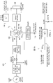
- FIGURE 1 illustrates an example hybrid energy storage system 100 according to this disclosure.
- the system 100 includes a high-voltage MVDC power input 105, a single high-voltage pulsed output 110, and a single energy storage battery or ultra-capacitor bank subsystem 115.
- the system 100 also includes a wound rotor induction machine 120 as a baseline electrical machine.
- the induction machine 120 is a DFIM.
- the system 100 features a combination of a high-voltage input and a DFIM used as the electrical machine. Total stored energy is partitioned between a flywheel 125 and the battery or ultra-capacitor bank subsystem 115, where each has different time constants and different speeds of response.
- the system 100 also includes a pulsed power AC bus (240 Hz), which becomes rectified to form a medium power DC pulsed power bus.
- FIGURE 1 may be the same as or similar to components in other HESM patent documents filed by the inventor, which include designs that supply primary power by an AC power system.
- These other HESM patent documents include U.S. Patent No. 9,531,289 ; U.S. Patent No. 9,373,963 ; U.S. Patent No. 9,531,247 ; U.S. Patent Publication No. 2016/0055971 ; U.S. Patent Publication No. 2016/0197600 ; and U.S. Patent Publication No. 2016/0336928 .
- specific values and specific component types in FIGURE 1 are examples only.
- FIGURE 1 illustrates one example of a hybrid energy storage system 100
- various changes may be made to FIGURE 1 .
- the system 100 shows one battery or ultra-capacitor bank subsystem 115
- other embodiments may include additional battery or ultra-capacitor bank subsystems.
- the makeup and arrangement of the system 100 are for illustration only. Components could be added, omitted, combined, or placed in any other configuration according to particular needs.
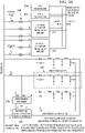
- FIGURES 2A and 2B illustrate another example hybrid energy storage system 200 according to an embodiment.
- the system 200 includes two or more independent MVDC inputs, two or more sources of synchronous electrical machine excitation, one main machine output for pulsed loads, and one auxiliary output for charging to a main battery or ultra-capacitor bank subsystem.
- the system 200 is an integrated system that allows two sources of medium voltage DC power from two turbine generators 210 and 216 to power an HESM, which has a synchronous electrical machine 202 with (for example) four input/output ports.
- This arrangement allows for a circumstantial mismatch in the source DC voltage levels or a deliberate use of two sources with widely different source voltage or power ratings. Additionally or alternatively, the use of two or more sources provides a redundancy capability for situations where one source is temporarily unavailable due to fault, maintenance, and the like.
- the turbine generators 210 and 216 feed two main power system rectifiers 212 and 218 to create bus nodes #1 and #2, which feed the electrical machine 202 through two filter inductors 214 and 224.
- the electrical machine 202 is a wound-field synchronous machine with a DC field winding and/or brushless exciter.
- the electrical machine 202 includes primary windings 203 and 204, each of which is powered by a separate variable-voltage variable-frequency (VVVF) power converter 220 and 221, respectively.
- VVVF power converters 220 and 221 are configured to operate the electrical machine 202 at adjustable speeds and stored energy levels.
- the primary windings 203 and 204 constitute two ports, which are bidirectional in power flow, are arranged on a common machine stator, and (in the most basic case) are equally rated in kW/kVA capacity and have the same flux/pole and voltage rating.
- the windings 203 and 204 can occupy a proportionate amount of stator peripheral volume in direct accordance with their kVA rating.
- the spatial winding layout of the electrical machine 202 permits the magnetic flux contributed by each winding 203 and 204 to be additive to the total machine airgap flux and additive to the total machine torque production.
- the arrangement allows one of the turbine generators 210 and 216 to provide the initial starting kinetic energy to bring the flywheel of an inertial flywheel storage unit 208 from a dead start to maximum speed. Thereafter, the kinetic energy is derived from the other turbine generator 210 and 216 to handle load swings over the upper speed range for modulation of shaft speed (such as from 75% to 100%).
- FIGURES 2A and 2B show only one main output port and one auxiliary bidirectional port, while FIGURES 3A and 3B (discussed below) show multiple output ports.
- the electrical machine 202 also includes a stator winding 206 that is designated as a tertiary winding and has dual-mode operation.
- the winding 206 is an input port that receives excitation energy from the battery or ultra-capacitor bank subsystem.
- the winding 206 can also operate as an output port to recharge an auxiliary battery 228. All ports can have high galvanic isolation from each other in order to protect inputs from output electrical transients and short circuits.
- the winding 206 includes a special fast excitation port, and this port has a fast response excitation current controller 230.
- each phase of the controller 230 could include a pulse forming network (PFN) of capacitor-inductor elements that are charged by the auxiliary battery 228 or other DC source such as an ultra-capacitor.
- PFN pulse forming network
- Each phase of the controller 230 contains an output thyristor-diode pair for discharging three or more PFNs in a sequential fashion so as to create a traveling wave excitation to the winding 206.
- This tertiary excitation normally boosts the main field excitation supplied by the rotor DC winding part of the slow excitation source 226 and also boosts the quadrature component of excitation provided by the primary winding(s). This arrangement provides for fast control of output pulses beyond normal generator control systems typical of conventional devices with only rotor DC current control.
- the auxiliary battery 228 represents a DC charging supply that is fed by either a high-density electrochemical battery system or an ultra-capacitor system, both of which are capable of long-term energy storage and at high capacity.
- Current technologies for these subsystems may limit the recharge rate for both types, and the electrical machine 202 may be better adapted for accepting high rates of recharge energy from the turbine generators 210 and 216.
- current battery and ultra-capacitor storage technologies are limited in safe maximum voltage (such as 1000 VDC) for a stacked module.
- embodiments of this disclosure combine with the electrical machine 202 to permit main output voltages to be much higher (such as 10kV to 100kV levels) without penalty or substantial reduction of efficiency.
- the system 200 also includes a conventional phase-delay bridge rectifier 232 (e.g., 6 or 12 pulse), an MVDC or HVDC pulsed load 234, a vacuum circuit breaker 236, an alternate VVVF converter 238, and an AC-DC converter 240 with a resonant type AC link and polyphase input.
- a conventional phase-delay bridge rectifier 232 e.g., 6 or 12 pulse
- an MVDC or HVDC pulsed load 234 e.g., 6 or 12 pulse
- MVDC or HVDC pulsed load 234 e.g., 6 or 12 pulse
- a vacuum circuit breaker 236, an alternate VVVF converter 238, and an AC-DC converter 240 with a resonant type AC link and polyphase input.
- FIGURES 2A and 2B illustrate another example of a hybrid energy storage system 200
- the system 200 could include three or more of each of the turbine generators, primary windings, and associated components.
- the makeup and arrangement of the system 200 are for illustration only. Components could be added, omitted, combined, or placed in any other configuration according to particular needs.
- FIGURES 3A and 3B illustrate yet another example hybrid energy storage system 300 according to an embodiment.
- the system 300 includes two MVDC sources and an electrical wound-rotor DFIM with five stator ports, one rotor port, and two types of energy storage.
- the system 300 features the wound-rotor DFIM as the primary electrical machine instead of the synchronous electrical machine 202 as in FIGURES 2A and 2B .
- two turbine generators 310 and 311 operate as sources of medium voltage DC power for an HESM that includes a DFIM 302.
- the DFIM 302 includes five stator ports with windings 303-307 and is mechanically coupled to a flywheel energy storage 308.
- the turbine generators 310 and 311 feed main power system rectifiers 312 and 317 to create bus nodes #1 and #2, which feed the DFIM 302 through filter inductors 323 and 324.
- Each primary winding 303 and 304 of the DFIM 302 is powered by a separate variable-voltage variable-frequency (VVVF) power converter 320 and 322, respectively.
- VVVF power converter 320 and 322 can represent or be represented by the VVVF converter 238 of FIGURES 2A and 2B .
- a polyphase rotor field 325 is excited from a DC-to-AC converter 326 that derives energy from an electrochemical battery or ultra-capacitor bank subsystem 328, which is shown as being charged from the tertiary stator winding 307 similar to a conventional "boot-strap" excitation scheme.
- the converter 326 can represent or be represented by the converter 238 of FIGURES 2A and 2B .
- Doubly-fed induction machines are well-known but typically have not been used with high slew-rate pulsed power.
- the system 300 offers greater operational flexibility than the system 200 by virtue of having a variable-frequency excited rotor field.
- the slip frequency of the rotor current 16 can be actively controlled by the converter 326 to yield mainly steady-state performance and to regulate the reactive kVA and real kVA outputs of two secondary windings 305 and 306 having output current I 3 and regenerative/reverse current I 4 .
- the windings 305 and 306 efficiently generate and absorb power into or out of the flywheel storage by use of separate rectifier-converter bridges 332 and 333.
- a PFN excitation circuit 330 can also be charged by the DFIM 302 in modes where fast excitation is not required or in the initial startup mode, since the stator tertiary winding 307 is bidirectional.
- a separate polyphase rectifier 329 derived from using the tertiary winding-induced voltage (when not in a pulsing output duty) is configured to charge the battery or ultra-capacitor bank subsystem 328, which subsequently charges three sets of capacitors in the PFN excitation circuit 330.
- the DFIM 302 is at its upper speed range, the DFIM 302 is most efficient in charging the battery or ultra-capacitor bank subsystem.
- the main output of the DFIM 302 is the secondary winding 305, which is a polyphase stator winding with high galvanic isolation from the other stator windings 303, 304, 306, 307, although the secondary winding 305 is built on the same stator core as the windings 303, 304, 306, 307.
- the windings 303-307 may appear segregated in certain peripheral zones in FIGURES 3A and 3B , in practice each winding 303-307 is a distributed winding around the machine periphery.
- the windings 305-307 may be wound in alternate stator slots.
- the windings 303 and 304 may be wound in upper and lower portions of the same stator slots.
- the winding 305 is a higher-voltage winding than the others and is connected through a system of vacuum interrupters 336 into a forward phase delay bridge 332.
- the switching elements for the bridge 332 may include thyristors, insulated gate bipolar transistors (IGBTs), integrated gate commutated thyristors (IGCTs), MOS-controlled thyristors (MCTs), or other solid-state switching devices with high voltage blocking ability.
- the switching elements also provide short circuit protection to the entire main output.
- the vacuum interrupters 336 can also serve as short circuit protection.
- the output of the bridge 332 is connected to multiple pulsed loads 334 and 335, which may be medium DC voltage or high DC voltage pulsed loads. By varying the thyristor phase angle delay, the output power is controlled to produce either a constant-voltage output or a constant-current output.
- the embodiments of this disclosure allow for sequential discharge or firing of the pulsed loads 334 and 335. Note that the output loads may actually include numerous loads (such as hundreds of modules) without restriction, and these modules can be grouped together into simultaneous firing groups with particular groups being sequentially fired.
- FIGURE 3C illustrates a PFN pulsed load circuit that can represent the pulsed loads 334 and 335 of FIGURES 3A and 3B or the pulsed load 234 of FIGURES 2A and 2B .
- the converter bridges 332 and 333 form a dual power converter system with fully bidirectional power flow.
- reverse power from a pulsed load is directed to the separate polyphase stator winding 306 through the reverse converter bridge 333.
- Situations may arise when the MVDC or HVDC power from the pulsed load 334 and 335 (which may include a large capacitor storage bank) cannot be used or dissipated in its intended use. Consequently, this energy is absorbed or transferred much faster in a flywheel energy storage 308 than the turbine generators or battery can accept.
- the stator winding 306 can be designed for slightly lower voltage or flux/pole rating than the winding 305. In doing so, this allows a more efficient transfer of load output energy to the DFIM 302 and hence rapid energy transfer to the flywheel energy storage 308 as a sink.
- FIGURES 3A and 3B illustrate another example of a hybrid energy storage system 300
- various changes may be made to FIGURES 3A and 3B .
- the makeup and arrangement of the system 300 are for illustration only. Components could be added, omitted, combined, or placed in any other configuration according to particular needs.
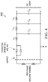
- FIGURE 4 illustrates an example PFN excitation circuit 400 for tertiary machine windings per phase according to this disclosure.
- the PFN excitation circuit 400 (or portions thereof) could be incorporated into (or used in conjunction with) the system 200 of FIGURES 2A-2B , the system 300 of FIGURES 3A-3B , or any other system.
- the PFN excitation circuit 400 is a three-stage PFN with output switches 441-443.
- the output switches 441-443 could be IGBT or thyristor switches with 100 kHz or greater switching frequency, although other switches could be used.
- Representative values for the PFN components in FIGURE 4 could include:
- One example use of the PFN excitation circuit 400 is to create a quasisinusoidal current waveform into the tertiary winding and to have the three solid-state switches triggered about 120° apart at whatever frequency is chosen. This creates a rapid response traveling wave of excitation, which is used for electrical machine excitation.
- the output voltage on the secondary windings 305 and 306 can rise rapidly (such as within microseconds) once the current in the tertiary winding 307 is established.
- the tertiary winding 307 has a minimum inductance in order to maximize the rate of rise of excitation current or maximize dv/dt and thus minimize the output pulse rise time.
- FIGURE 4 illustrates one example of a PFN excitation circuit 400
- various changes may be made to FIGURE 4 .
- FIGURE 4 shows a three-stage PFN, this is merely one example.
- the PFN excitation circuit 400 can have more than three or fewer than three stages.
- the makeup and arrangement of the PFN excitation circuit 400 are for illustration only. Components could be added, omitted, combined, or placed in any other configuration according to particular needs.
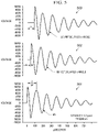
- FIGURE 5 illustrates example waveforms 501-503 for PFN excitation of the tertiary winding with three-phase triggered switches and 120° offset between each wave, according to this disclosure.
- the waveforms 501-503 could, for example, be used by the PFN excitation circuit 400 of FIGURE 4 in the systems 200, 300.
- FIGURE 5 shows the waveforms 501-503 created by a PFN-type excitation into a machine stator tertiary winding (such as the winding 307 of FIGURE 3A ).
- This creates a "traveling wave" of excitation of the machine magnetic flux, a very rapid rise of output pulsed power, and a decaying oscillation of applied excitation voltage (such as over seven cycles after the output switches 441-443, as thyristor devices, are triggered).
- the very rapid rise of output pulsed power occurs in an approximately 121 ⁇ s period time (about 8264 Hz frequency).
- FIGURE 5 illustrates examples of waveforms for PFN excitation
- various changes may be made to FIGURE 5 .
- FIGURE 5 shows three waveforms from three switches, this is merely one example.
- the PFN excitation circuit can have more than three or fewer than three stages, resulting in more or fewer waveforms.
Landscapes
- Engineering & Computer Science (AREA)
- Power Engineering (AREA)
- Control Of Eletrric Generators (AREA)
- Electric Propulsion And Braking For Vehicles (AREA)
- Charge And Discharge Circuits For Batteries Or The Like (AREA)
- Inverter Devices (AREA)
Claims (6)
- System (200, 300), das Folgendes umfasst:erste und zweite Quellen (210, 216; 310, 311), die konfiguriert sind, um Leistung an erste beziehungsweise zweite Mittelspannungsgleichstrom(medium-voltage direct current - MVDC)-Busse bereitzustellen; wobei die ersten und zweiten MVDC-Busse mit ersten beziehungsweise zweiten Spannungsvariablen-Frequenzvariablen(variable-voltage variable-frequency - VVVF)-Leistungswandlern (220, 221; 320, 322) verbunden sind;eine rotierende elektrische Maschine (202; 302), die erste und zweite Primärstatorwicklungen (203, 204; 303, 304) und erste und zweite Sekundärstatorwicklungen (305, 306) aufweist, wobei jede Primärstatorwicklung (203, 204; 303, 304) mit einem der ersten und zweiten MVDC-Busse über einen der ersten und zweiten VVVF-Leistungswandler (220, 221; 320, 322) elektrisch verbunden ist, wobei die rotierende elektrische Maschine (202; 302) konfiguriert ist, um die Leistung von den ersten und zweiten MVDC-Bussen aufzunehmen, wobei jede Sekundärstatorwicklung konfiguriert ist, um Ausgangsleistung an eine gepulste Last (234; 334, 335) bereitzustellen;einen Schwungradenergiespeicher (208; 308), der mit der rotierenden elektrischen Maschine (202; 302) gekoppelt und konfiguriert ist, um Trägheitsenergie zu speichern; undwenigstens ein Batterie- oder Ultrakondensatorteilsystem (228; 328), das mit der rotierenden elektrischen Maschine (202; 302) elektrisch verbunden ist, wobei das wenigstens eine Batterie- oder Ultrakondensatorteilsystem (228; 328) konfiguriert ist, um elektrische Energie von der rotierenden elektrischen Maschine (202; 302) aufzunehmen und dieser elektrische Energie bereitzustellen;wobei jeder VVVF-Leistungswandler (220, 221; 320, 322) konfiguriert ist, um die rotierende elektrische Maschine (202; 302) mit einstellbaren Geschwindigkeiten und gespeicherten Energiewerten zu betreiben.
- System nach Anspruch 1, wobei die erste Sekundärstatorwicklung (305) mit einer Vorwärts-Wechselstrom-zu-Gleichstrom-Wandlerbrücke (332) elektrisch verbunden ist und die zweite Sekundärstatorwicklung (306) mit einer Umgekehrt-Wechselstrom-zu-Gleichstrom-Wandlerbrücke (333) für einen bidirektionalen Leistungsfluss elektrisch verbunden ist.
- System nach Anspruch 1, wobei das wenigstens eine Batterie- oder Ultrakondensatorteilsystem (228; 328) mit einer Tertiärstatorwicklung (206; 307) der rotierenden elektrischen Maschine (202; 302) elektrisch verbunden ist.
- System nach Anspruch 1, das ferner Folgendes umfasst:
einen Erregerkreis (230; 330) eines impulsformenden Netzwerks (pulse forming network - PFN), der konfiguriert ist, um durch die rotierende elektrische Maschine (202; 302) unter Verwendung von Energie geladen zu werden, die durch den Schwungradenergiespeicher (208; 308) bereitgestellt wird. - System nach Anspruch 1, wobei die rotierende elektrische Maschine (202; 302) eine elektrische Maschine mit doppelt gespeister Induktion (doubly-fed induction electrical machine - DFIM) umfasst.
- System nach Anspruch 1, wobei die Ausgangsleistung konfiguriert werden kann, um eine Konstantspannungsausgangsleistung, eine Konstantstromausgangsleistung oder eine Kombination von beiden zu sein.
Priority Applications (2)
| Application Number | Priority Date | Filing Date | Title |
|---|---|---|---|
| EP21155136.1A EP3836333B1 (de) | 2016-04-01 | 2017-03-31 | Hybridenergiespeichermodule für pulsleistungseffektoren mit mittelspannungsgleichstrom (mvdc)-leistungsverteilung |
| EP21155083.5A EP3836332A1 (de) | 2016-04-01 | 2017-03-31 | Hybridenergiespeichermodule für pulsleistungseffektoren mit mittelspannungsgleichstrom (mvdc)-leistungsverteilung |
Applications Claiming Priority (2)
| Application Number | Priority Date | Filing Date | Title |
|---|---|---|---|
| US201662317431P | 2016-04-01 | 2016-04-01 | |
| PCT/US2017/025619 WO2018004765A2 (en) | 2016-04-01 | 2017-03-31 | Hybrid energy storage modules for pulsed power effectors with medium voltage direct current (mvdc) power distribution |
Related Child Applications (4)
| Application Number | Title | Priority Date | Filing Date |
|---|---|---|---|
| EP21155136.1A Division EP3836333B1 (de) | 2016-04-01 | 2017-03-31 | Hybridenergiespeichermodule für pulsleistungseffektoren mit mittelspannungsgleichstrom (mvdc)-leistungsverteilung |
| EP21155136.1A Division-Into EP3836333B1 (de) | 2016-04-01 | 2017-03-31 | Hybridenergiespeichermodule für pulsleistungseffektoren mit mittelspannungsgleichstrom (mvdc)-leistungsverteilung |
| EP21155083.5A Division EP3836332A1 (de) | 2016-04-01 | 2017-03-31 | Hybridenergiespeichermodule für pulsleistungseffektoren mit mittelspannungsgleichstrom (mvdc)-leistungsverteilung |
| EP21155083.5A Division-Into EP3836332A1 (de) | 2016-04-01 | 2017-03-31 | Hybridenergiespeichermodule für pulsleistungseffektoren mit mittelspannungsgleichstrom (mvdc)-leistungsverteilung |
Publications (2)
| Publication Number | Publication Date |
|---|---|
| EP3437170A2 EP3437170A2 (de) | 2019-02-06 |
| EP3437170B1 true EP3437170B1 (de) | 2022-05-04 |
Family
ID=60143744
Family Applications (3)
| Application Number | Title | Priority Date | Filing Date |
|---|---|---|---|
| EP17787271.0A Active EP3437170B1 (de) | 2016-04-01 | 2017-03-31 | Hybridenergiespeichermodule für pulsleistungseffektoren mit mittelspannungsgleichstrom (mvdc)-leistungsverteilung |
| EP21155136.1A Active EP3836333B1 (de) | 2016-04-01 | 2017-03-31 | Hybridenergiespeichermodule für pulsleistungseffektoren mit mittelspannungsgleichstrom (mvdc)-leistungsverteilung |
| EP21155083.5A Pending EP3836332A1 (de) | 2016-04-01 | 2017-03-31 | Hybridenergiespeichermodule für pulsleistungseffektoren mit mittelspannungsgleichstrom (mvdc)-leistungsverteilung |
Family Applications After (2)
| Application Number | Title | Priority Date | Filing Date |
|---|---|---|---|
| EP21155136.1A Active EP3836333B1 (de) | 2016-04-01 | 2017-03-31 | Hybridenergiespeichermodule für pulsleistungseffektoren mit mittelspannungsgleichstrom (mvdc)-leistungsverteilung |
| EP21155083.5A Pending EP3836332A1 (de) | 2016-04-01 | 2017-03-31 | Hybridenergiespeichermodule für pulsleistungseffektoren mit mittelspannungsgleichstrom (mvdc)-leistungsverteilung |
Country Status (3)
| Country | Link |
|---|---|
| US (3) | US10985563B2 (de) |
| EP (3) | EP3437170B1 (de) |
| WO (1) | WO2018004765A2 (de) |
Families Citing this family (29)
| Publication number | Priority date | Publication date | Assignee | Title |
|---|---|---|---|---|
| US11038398B2 (en) * | 2018-06-26 | 2021-06-15 | Raytheon Company | System and method for damping of torsional oscillations in large inertial energy storage systems |
| KR102800768B1 (ko) | 2018-07-31 | 2025-04-25 | 시온 파워 코퍼레이션 | 멀티플렉스 충전 방전 배터리 관리 시스템 |
| CN209218129U (zh) * | 2018-12-29 | 2019-08-06 | 中国人民解放军陆军工程大学 | 神经形态仿生调制电路和通信系统 |
| US10879812B2 (en) * | 2019-04-09 | 2020-12-29 | Wisconsin Alumni Research Foundation | Semiconductor switch |
| US11616378B2 (en) * | 2019-06-11 | 2023-03-28 | Raytheon Company | Power transfer system with multiple energy storage modules |
| US11489367B2 (en) | 2019-06-11 | 2022-11-01 | Raytheon Company | Polyphase contactless induction power transfer system for transferring electrical power across gap |
| US11056728B2 (en) | 2019-10-31 | 2021-07-06 | Sion Power Corporation | System and method for operating a rechargeable electrochemical cell or battery |
| US11424492B2 (en) | 2019-10-31 | 2022-08-23 | Sion Power Corporation | System and method for operating a rechargeable electrochemical cell or battery |
| US10958254B1 (en) * | 2020-01-09 | 2021-03-23 | Raytheon Company | Energy storage module with XRAM current multiplier |
| IT202000005371A1 (it) * | 2020-03-12 | 2021-09-12 | Danieli Automation Spa | Apparecchiatura e procedimento di controllo per controllare un motore elettrico di elevata potenza |
| GB202007819D0 (en) * | 2020-05-26 | 2020-07-08 | Siemens Ag | DC grid |
| JP6923722B1 (ja) * | 2020-07-28 | 2021-08-25 | 日立建機株式会社 | ドライブシステム |
| WO2022051308A1 (en) | 2020-09-01 | 2022-03-10 | Sion Power Corporation | Multiplexed battery management system |
| US11742661B2 (en) | 2020-10-16 | 2023-08-29 | Raytheon Company | Augmented bus impedance and thump control for electrical power systems |
| CN112383075B (zh) * | 2020-11-13 | 2022-06-03 | 太原理工大学 | 一种共直流母线多机运行储能系统能量管理控制装置 |
| CN112477690B (zh) * | 2020-11-13 | 2022-02-01 | 太原理工大学 | 一种新能源汽车驱动系统能量动态分配与优化控制装置 |
| US20220336872A1 (en) | 2021-02-05 | 2022-10-20 | Sion Power Corporation | Charge/discharge management in electrochemical cells, including partial cycle control |
| US11632021B2 (en) | 2021-04-05 | 2023-04-18 | Raytheon Company | Dynamo-electric machine |
| US11742683B2 (en) * | 2021-04-14 | 2023-08-29 | Toyota Motor Engineering & Manufacturing North America, Inc. | Managing storage of electrical energy |
| EP4338249B1 (de) | 2021-05-10 | 2025-07-02 | Terna S.p.A. | Doppeltgespeistes schwungradsystem mit fähigkeit zur bereitstellung eines doppelten trägheitsbeitrags, natürlicher und synthetischer und innovativer betriebslogik |
| IT202100017042A1 (it) * | 2021-06-29 | 2022-12-29 | Terna S P A | Sistema a volano a doppia alimentazione con capacita' di erogazione di un doppio contributo inerziale, naturale e sintetico, e relativa logica di funzionamento innovativa |
| US12088108B2 (en) | 2021-06-08 | 2024-09-10 | Hamilton Sundstrand Corporation | Smart power router and protection for medium voltage DC distribution |
| NO347044B1 (en) * | 2021-10-11 | 2023-04-24 | Kongsberg Maritime As | Onboard medium-voltage vessel electric charging apparatus and method for onboard charging. |
| US12136844B2 (en) * | 2021-12-21 | 2024-11-05 | Raytheon Company | Energy storage power source using a wound-rotor induction machine (WRIM) to charge and discharge energy storage elements (ESEs) |
| EP4391276A1 (de) * | 2022-12-20 | 2024-06-26 | Abb Schweiz Ag | Stromverteilungsanordnung |
| CN118264131A (zh) * | 2022-12-28 | 2024-06-28 | 台达电子工业股份有限公司 | 中压电源转换系统与分散式中压电源转换系统 |
| US12261560B2 (en) | 2023-05-03 | 2025-03-25 | Raytheon Company | Active harmonic filter and reactive power control system for naval ship power systems |
| WO2025155658A1 (en) * | 2024-01-16 | 2025-07-24 | Magna International Inc. | Battery integrated modular power electronic architectures and controls |
| US20250330066A1 (en) * | 2024-04-17 | 2025-10-23 | Raytheon Company | Multi-port energy storage system and control for laser power supply |
Family Cites Families (17)
| Publication number | Priority date | Publication date | Assignee | Title |
|---|---|---|---|---|
| US3975646A (en) * | 1975-01-13 | 1976-08-17 | Westinghouse Electric Corporation | Asynchronous tie |
| US5239250A (en) * | 1983-08-04 | 1993-08-24 | Allied-Signal Inc. | Capacitor-assisted line commutation for induction motor drives |
| US7071581B2 (en) * | 2001-01-31 | 2006-07-04 | Satcon Technology Corp. | Uninterruptible power supply system using a slip-ring, wound-rotor-type induction machine and a method for flywheel energy storage |
| DE102007014728A1 (de) | 2007-03-24 | 2008-10-02 | Woodward Seg Gmbh & Co. Kg | Verfahren und Vorrichtung zum Betrieb einer doppeltgespeisten Asynchronmaschine bei transienten Netzspannungsänderungen |
| EP2293407A1 (de) * | 2009-09-08 | 2011-03-09 | Converteam Technology Ltd | Energieübertragungs- und Verteilungssysteme |
| EP2394908B1 (de) * | 2010-06-08 | 2013-03-06 | GE Energy Power Conversion Technology Limited | Stromverteilungssystem und Verfahren für seine Steuerung. |
| US8624431B2 (en) * | 2011-02-26 | 2014-01-07 | General Electric Company | System and method for power sharing of front-end converters without communication link in a modular-stacked DC transmission system |
| US8558405B2 (en) * | 2011-05-26 | 2013-10-15 | Siemens Aktiengesellschaft | Method and system for operating and controlling a wind turbine to prevent excitation of subsynchronous oscillations within the wind turbine |
| US9531289B2 (en) | 2012-04-27 | 2016-12-27 | Raytheon Company | Electro-mechanical kinetic energy storage device and method of operation |
| US9373963B2 (en) | 2013-05-24 | 2016-06-21 | Raytheon Company | Energy transfer and storage apparatus for delivery of pulsed power |
| EP3968511A1 (de) * | 2013-09-04 | 2022-03-16 | General Electric Technology GmbH | Stromwandler |
| US9531247B2 (en) * | 2014-04-04 | 2016-12-27 | Raytheon Company | Inertial energy storage system and hydro-fluoro-ether power transformer scheme for radar power systems and large PFN charging |
| KR102224824B1 (ko) * | 2014-05-30 | 2021-03-08 | 삼성전자 주식회사 | Ito 전극패턴을 포함하는 전자장치 및 그 전자장치의 제조방법 |
| US9911532B2 (en) | 2014-08-25 | 2018-03-06 | Raytheon Company | Forced convection liquid cooling of fluid-filled high density pulsed power capacitor with native fluid |
| US9837996B2 (en) | 2015-01-07 | 2017-12-05 | Raytheon Company | Method and apparatus for control of pulsed power in hybrid energy storage module |
| US9667232B2 (en) | 2015-05-13 | 2017-05-30 | Raytheon Company | System and method for parallel configuration of hybrid energy storage module |
| US10450080B1 (en) * | 2016-03-28 | 2019-10-22 | United States Of America As Represented By The Administrator Of National Aeronautics And Space Administration | Variable frequency power system for hybrid electric aircraft propulsion |
-
2017
- 2017-03-31 EP EP17787271.0A patent/EP3437170B1/de active Active
- 2017-03-31 EP EP21155136.1A patent/EP3836333B1/de active Active
- 2017-03-31 EP EP21155083.5A patent/EP3836332A1/de active Pending
- 2017-03-31 WO PCT/US2017/025619 patent/WO2018004765A2/en not_active Ceased
-
2018
- 2018-10-01 US US16/148,331 patent/US10985563B2/en active Active
-
2020
- 2020-11-04 US US17/089,671 patent/US11404876B2/en active Active
- 2020-11-04 US US17/089,592 patent/US11418035B2/en active Active
Also Published As
| Publication number | Publication date |
|---|---|
| WO2018004765A3 (en) | 2018-03-08 |
| US11418035B2 (en) | 2022-08-16 |
| EP3836332A1 (de) | 2021-06-16 |
| EP3836333B1 (de) | 2026-01-07 |
| WO2018004765A2 (en) | 2018-01-04 |
| US11404876B2 (en) | 2022-08-02 |
| US10985563B2 (en) | 2021-04-20 |
| US20210376610A1 (en) | 2021-12-02 |
| EP3437170A2 (de) | 2019-02-06 |
| US20190036336A1 (en) | 2019-01-31 |
| US20210075217A1 (en) | 2021-03-11 |
| EP3836333A1 (de) | 2021-06-16 |
Similar Documents
| Publication | Publication Date | Title |
|---|---|---|
| US11418035B2 (en) | Hybrid energy storage modules for pulsed power effectors with medium voltage direct current (MVDC) power distribution | |
| US10298212B2 (en) | Method and apparatus for control of pulsed power in hybrid energy storage module | |
| US10491074B2 (en) | Electro-mechanical kinetic energy storage device and method of operation | |
| US9667232B2 (en) | System and method for parallel configuration of hybrid energy storage module | |
| JP6335327B2 (ja) | レーダーパワーシステム及び大規模pfn充電のための慣性エネルギ貯蔵システム及びハイドロフルオロエーテル電力変圧器スキーム | |
| US9373963B2 (en) | Energy transfer and storage apparatus for delivery of pulsed power | |
| JP7297106B2 (ja) | 複数のエネルギー蓄積モジュールを有する電力伝達システム | |
| US12027940B2 (en) | Rectifier | |
| RU2411629C1 (ru) | Многоуровневый транзисторный преобразователь частоты для управления электродвигателем переменного тока | |
| Kuznetsov | Advanced AC to AC power conversion techniques for naval ship propulsion drives |
Legal Events
| Date | Code | Title | Description |
|---|---|---|---|
| STAA | Information on the status of an ep patent application or granted ep patent |
Free format text: STATUS: UNKNOWN |
|
| STAA | Information on the status of an ep patent application or granted ep patent |
Free format text: STATUS: THE INTERNATIONAL PUBLICATION HAS BEEN MADE |
|
| PUAI | Public reference made under article 153(3) epc to a published international application that has entered the european phase |
Free format text: ORIGINAL CODE: 0009012 |
|
| STAA | Information on the status of an ep patent application or granted ep patent |
Free format text: STATUS: REQUEST FOR EXAMINATION WAS MADE |
|
| 17P | Request for examination filed |
Effective date: 20181022 |
|
| AK | Designated contracting states |
Kind code of ref document: A2 Designated state(s): AL AT BE BG CH CY CZ DE DK EE ES FI FR GB GR HR HU IE IS IT LI LT LU LV MC MK MT NL NO PL PT RO RS SE SI SK SM TR |
|
| AX | Request for extension of the european patent |
Extension state: BA ME |
|
| DAV | Request for validation of the european patent (deleted) | ||
| DAX | Request for extension of the european patent (deleted) | ||
| STAA | Information on the status of an ep patent application or granted ep patent |
Free format text: STATUS: EXAMINATION IS IN PROGRESS |
|
| 17Q | First examination report despatched |
Effective date: 20201015 |
|
| GRAP | Despatch of communication of intention to grant a patent |
Free format text: ORIGINAL CODE: EPIDOSNIGR1 |
|
| STAA | Information on the status of an ep patent application or granted ep patent |
Free format text: STATUS: GRANT OF PATENT IS INTENDED |
|
| RIC1 | Information provided on ipc code assigned before grant |
Ipc: H02J 3/32 20060101ALI20210930BHEP Ipc: H02P 25/22 20060101ALI20210930BHEP Ipc: H03K 3/57 20060101ALI20210930BHEP Ipc: H02J 3/30 20060101AFI20210930BHEP |
|
| INTG | Intention to grant announced |
Effective date: 20211021 |
|
| GRAJ | Information related to disapproval of communication of intention to grant by the applicant or resumption of examination proceedings by the epo deleted |
Free format text: ORIGINAL CODE: EPIDOSDIGR1 |
|
| STAA | Information on the status of an ep patent application or granted ep patent |
Free format text: STATUS: EXAMINATION IS IN PROGRESS |
|
| INTC | Intention to grant announced (deleted) | ||
| GRAP | Despatch of communication of intention to grant a patent |
Free format text: ORIGINAL CODE: EPIDOSNIGR1 |
|
| STAA | Information on the status of an ep patent application or granted ep patent |
Free format text: STATUS: GRANT OF PATENT IS INTENDED |
|
| GRAS | Grant fee paid |
Free format text: ORIGINAL CODE: EPIDOSNIGR3 |
|
| INTG | Intention to grant announced |
Effective date: 20220221 |
|
| GRAA | (expected) grant |
Free format text: ORIGINAL CODE: 0009210 |
|
| STAA | Information on the status of an ep patent application or granted ep patent |
Free format text: STATUS: THE PATENT HAS BEEN GRANTED |
|
| AK | Designated contracting states |
Kind code of ref document: B1 Designated state(s): AL AT BE BG CH CY CZ DE DK EE ES FI FR GB GR HR HU IE IS IT LI LT LU LV MC MK MT NL NO PL PT RO RS SE SI SK SM TR |
|
| REG | Reference to a national code |
Ref country code: GB Ref legal event code: FG4D |
|
| REG | Reference to a national code |
Ref country code: CH Ref legal event code: EP |
|
| REG | Reference to a national code |
Ref country code: AT Ref legal event code: REF Ref document number: 1490151 Country of ref document: AT Kind code of ref document: T Effective date: 20220515 |
|
| REG | Reference to a national code |
Ref country code: IE Ref legal event code: FG4D Ref country code: DE Ref legal event code: R096 Ref document number: 602017056990 Country of ref document: DE |
|
| REG | Reference to a national code |
Ref country code: SE Ref legal event code: TRGR |
|
| REG | Reference to a national code |
Ref country code: NO Ref legal event code: T2 Effective date: 20220504 |
|
| REG | Reference to a national code |
Ref country code: LT Ref legal event code: MG9D |
|
| REG | Reference to a national code |
Ref country code: NL Ref legal event code: MP Effective date: 20220504 |
|
| REG | Reference to a national code |
Ref country code: AT Ref legal event code: MK05 Ref document number: 1490151 Country of ref document: AT Kind code of ref document: T Effective date: 20220504 |
|
| PG25 | Lapsed in a contracting state [announced via postgrant information from national office to epo] |
Ref country code: PT Free format text: LAPSE BECAUSE OF FAILURE TO SUBMIT A TRANSLATION OF THE DESCRIPTION OR TO PAY THE FEE WITHIN THE PRESCRIBED TIME-LIMIT Effective date: 20220905 Ref country code: NL Free format text: LAPSE BECAUSE OF FAILURE TO SUBMIT A TRANSLATION OF THE DESCRIPTION OR TO PAY THE FEE WITHIN THE PRESCRIBED TIME-LIMIT Effective date: 20220504 Ref country code: LT Free format text: LAPSE BECAUSE OF FAILURE TO SUBMIT A TRANSLATION OF THE DESCRIPTION OR TO PAY THE FEE WITHIN THE PRESCRIBED TIME-LIMIT Effective date: 20220504 Ref country code: HR Free format text: LAPSE BECAUSE OF FAILURE TO SUBMIT A TRANSLATION OF THE DESCRIPTION OR TO PAY THE FEE WITHIN THE PRESCRIBED TIME-LIMIT Effective date: 20220504 Ref country code: GR Free format text: LAPSE BECAUSE OF FAILURE TO SUBMIT A TRANSLATION OF THE DESCRIPTION OR TO PAY THE FEE WITHIN THE PRESCRIBED TIME-LIMIT Effective date: 20220805 Ref country code: FI Free format text: LAPSE BECAUSE OF FAILURE TO SUBMIT A TRANSLATION OF THE DESCRIPTION OR TO PAY THE FEE WITHIN THE PRESCRIBED TIME-LIMIT Effective date: 20220504 Ref country code: ES Free format text: LAPSE BECAUSE OF FAILURE TO SUBMIT A TRANSLATION OF THE DESCRIPTION OR TO PAY THE FEE WITHIN THE PRESCRIBED TIME-LIMIT Effective date: 20220504 Ref country code: BG Free format text: LAPSE BECAUSE OF FAILURE TO SUBMIT A TRANSLATION OF THE DESCRIPTION OR TO PAY THE FEE WITHIN THE PRESCRIBED TIME-LIMIT Effective date: 20220804 Ref country code: AT Free format text: LAPSE BECAUSE OF FAILURE TO SUBMIT A TRANSLATION OF THE DESCRIPTION OR TO PAY THE FEE WITHIN THE PRESCRIBED TIME-LIMIT Effective date: 20220504 |
|
| PG25 | Lapsed in a contracting state [announced via postgrant information from national office to epo] |
Ref country code: RS Free format text: LAPSE BECAUSE OF FAILURE TO SUBMIT A TRANSLATION OF THE DESCRIPTION OR TO PAY THE FEE WITHIN THE PRESCRIBED TIME-LIMIT Effective date: 20220504 Ref country code: PL Free format text: LAPSE BECAUSE OF FAILURE TO SUBMIT A TRANSLATION OF THE DESCRIPTION OR TO PAY THE FEE WITHIN THE PRESCRIBED TIME-LIMIT Effective date: 20220504 Ref country code: LV Free format text: LAPSE BECAUSE OF FAILURE TO SUBMIT A TRANSLATION OF THE DESCRIPTION OR TO PAY THE FEE WITHIN THE PRESCRIBED TIME-LIMIT Effective date: 20220504 Ref country code: IS Free format text: LAPSE BECAUSE OF FAILURE TO SUBMIT A TRANSLATION OF THE DESCRIPTION OR TO PAY THE FEE WITHIN THE PRESCRIBED TIME-LIMIT Effective date: 20220904 |
|
| PG25 | Lapsed in a contracting state [announced via postgrant information from national office to epo] |
Ref country code: SM Free format text: LAPSE BECAUSE OF FAILURE TO SUBMIT A TRANSLATION OF THE DESCRIPTION OR TO PAY THE FEE WITHIN THE PRESCRIBED TIME-LIMIT Effective date: 20220504 Ref country code: SK Free format text: LAPSE BECAUSE OF FAILURE TO SUBMIT A TRANSLATION OF THE DESCRIPTION OR TO PAY THE FEE WITHIN THE PRESCRIBED TIME-LIMIT Effective date: 20220504 Ref country code: RO Free format text: LAPSE BECAUSE OF FAILURE TO SUBMIT A TRANSLATION OF THE DESCRIPTION OR TO PAY THE FEE WITHIN THE PRESCRIBED TIME-LIMIT Effective date: 20220504 Ref country code: EE Free format text: LAPSE BECAUSE OF FAILURE TO SUBMIT A TRANSLATION OF THE DESCRIPTION OR TO PAY THE FEE WITHIN THE PRESCRIBED TIME-LIMIT Effective date: 20220504 Ref country code: DK Free format text: LAPSE BECAUSE OF FAILURE TO SUBMIT A TRANSLATION OF THE DESCRIPTION OR TO PAY THE FEE WITHIN THE PRESCRIBED TIME-LIMIT Effective date: 20220504 Ref country code: CZ Free format text: LAPSE BECAUSE OF FAILURE TO SUBMIT A TRANSLATION OF THE DESCRIPTION OR TO PAY THE FEE WITHIN THE PRESCRIBED TIME-LIMIT Effective date: 20220504 |
|
| REG | Reference to a national code |
Ref country code: DE Ref legal event code: R097 Ref document number: 602017056990 Country of ref document: DE |
|
| PLBE | No opposition filed within time limit |
Free format text: ORIGINAL CODE: 0009261 |
|
| STAA | Information on the status of an ep patent application or granted ep patent |
Free format text: STATUS: NO OPPOSITION FILED WITHIN TIME LIMIT |
|
| PG25 | Lapsed in a contracting state [announced via postgrant information from national office to epo] |
Ref country code: AL Free format text: LAPSE BECAUSE OF FAILURE TO SUBMIT A TRANSLATION OF THE DESCRIPTION OR TO PAY THE FEE WITHIN THE PRESCRIBED TIME-LIMIT Effective date: 20220504 |
|
| 26N | No opposition filed |
Effective date: 20230207 |
|
| PG25 | Lapsed in a contracting state [announced via postgrant information from national office to epo] |
Ref country code: SI Free format text: LAPSE BECAUSE OF FAILURE TO SUBMIT A TRANSLATION OF THE DESCRIPTION OR TO PAY THE FEE WITHIN THE PRESCRIBED TIME-LIMIT Effective date: 20220504 |
|
| P01 | Opt-out of the competence of the unified patent court (upc) registered |
Effective date: 20230530 |
|
| PG25 | Lapsed in a contracting state [announced via postgrant information from national office to epo] |
Ref country code: MC Free format text: LAPSE BECAUSE OF FAILURE TO SUBMIT A TRANSLATION OF THE DESCRIPTION OR TO PAY THE FEE WITHIN THE PRESCRIBED TIME-LIMIT Effective date: 20220504 |
|
| REG | Reference to a national code |
Ref country code: CH Ref legal event code: PL |
|
| REG | Reference to a national code |
Ref country code: BE Ref legal event code: MM Effective date: 20230331 |
|
| PG25 | Lapsed in a contracting state [announced via postgrant information from national office to epo] |
Ref country code: LU Free format text: LAPSE BECAUSE OF NON-PAYMENT OF DUE FEES Effective date: 20230331 |
|
| REG | Reference to a national code |
Ref country code: IE Ref legal event code: MM4A |
|
| PG25 | Lapsed in a contracting state [announced via postgrant information from national office to epo] |
Ref country code: LI Free format text: LAPSE BECAUSE OF NON-PAYMENT OF DUE FEES Effective date: 20230331 Ref country code: IE Free format text: LAPSE BECAUSE OF NON-PAYMENT OF DUE FEES Effective date: 20230331 Ref country code: CH Free format text: LAPSE BECAUSE OF NON-PAYMENT OF DUE FEES Effective date: 20230331 |
|
| PG25 | Lapsed in a contracting state [announced via postgrant information from national office to epo] |
Ref country code: BE Free format text: LAPSE BECAUSE OF NON-PAYMENT OF DUE FEES Effective date: 20230331 |
|
| PG25 | Lapsed in a contracting state [announced via postgrant information from national office to epo] |
Ref country code: BG Free format text: LAPSE BECAUSE OF FAILURE TO SUBMIT A TRANSLATION OF THE DESCRIPTION OR TO PAY THE FEE WITHIN THE PRESCRIBED TIME-LIMIT Effective date: 20220504 |
|
| PG25 | Lapsed in a contracting state [announced via postgrant information from national office to epo] |
Ref country code: BG Free format text: LAPSE BECAUSE OF FAILURE TO SUBMIT A TRANSLATION OF THE DESCRIPTION OR TO PAY THE FEE WITHIN THE PRESCRIBED TIME-LIMIT Effective date: 20220504 |
|
| PG25 | Lapsed in a contracting state [announced via postgrant information from national office to epo] |
Ref country code: CY Free format text: LAPSE BECAUSE OF FAILURE TO SUBMIT A TRANSLATION OF THE DESCRIPTION OR TO PAY THE FEE WITHIN THE PRESCRIBED TIME-LIMIT; INVALID AB INITIO Effective date: 20170331 |
|
| PG25 | Lapsed in a contracting state [announced via postgrant information from national office to epo] |
Ref country code: HU Free format text: LAPSE BECAUSE OF FAILURE TO SUBMIT A TRANSLATION OF THE DESCRIPTION OR TO PAY THE FEE WITHIN THE PRESCRIBED TIME-LIMIT; INVALID AB INITIO Effective date: 20170331 |
|
| PG25 | Lapsed in a contracting state [announced via postgrant information from national office to epo] |
Ref country code: TR Free format text: LAPSE BECAUSE OF FAILURE TO SUBMIT A TRANSLATION OF THE DESCRIPTION OR TO PAY THE FEE WITHIN THE PRESCRIBED TIME-LIMIT Effective date: 20220504 |
|
| PGFP | Annual fee paid to national office [announced via postgrant information from national office to epo] |
Ref country code: SE Payment date: 20260219 Year of fee payment: 10 |
|
| PGFP | Annual fee paid to national office [announced via postgrant information from national office to epo] |
Ref country code: GB Payment date: 20260220 Year of fee payment: 10 |
|
| PGFP | Annual fee paid to national office [announced via postgrant information from national office to epo] |
Ref country code: DE Payment date: 20260219 Year of fee payment: 10 Ref country code: NO Payment date: 20260223 Year of fee payment: 10 |
|
| PGFP | Annual fee paid to national office [announced via postgrant information from national office to epo] |
Ref country code: IT Payment date: 20260219 Year of fee payment: 10 |
|
| PGFP | Annual fee paid to national office [announced via postgrant information from national office to epo] |
Ref country code: FR Payment date: 20260219 Year of fee payment: 10 |