EP3437183B1 - Vorrichtung zur regelung einer lichtmaschine eines kraftfahrzeugs und entsprechende lichtmaschine - Google Patents
Vorrichtung zur regelung einer lichtmaschine eines kraftfahrzeugs und entsprechende lichtmaschine Download PDFInfo
- Publication number
- EP3437183B1 EP3437183B1 EP17713717.1A EP17713717A EP3437183B1 EP 3437183 B1 EP3437183 B1 EP 3437183B1 EP 17713717 A EP17713717 A EP 17713717A EP 3437183 B1 EP3437183 B1 EP 3437183B1
- Authority
- EP
- European Patent Office
- Prior art keywords
- temperature
- excitation
- alternator
- speed
- current
- Prior art date
- Legal status (The legal status is an assumption and is not a legal conclusion. Google has not performed a legal analysis and makes no representation as to the accuracy of the status listed.)
- Active
Links
Images







Classifications
-
- H—ELECTRICITY
- H02—GENERATION; CONVERSION OR DISTRIBUTION OF ELECTRIC POWER
- H02P—CONTROL OR REGULATION OF ELECTRIC MOTORS, ELECTRIC GENERATORS OR DYNAMO-ELECTRIC CONVERTERS; CONTROLLING TRANSFORMERS, REACTORS OR CHOKE COILS
- H02P9/00—Arrangements for controlling electric generators for the purpose of obtaining a desired output
- H02P9/14—Arrangements for controlling electric generators for the purpose of obtaining a desired output by variation of field
- H02P9/26—Arrangements for controlling electric generators for the purpose of obtaining a desired output by variation of field using discharge tubes or semiconductor devices
- H02P9/30—Arrangements for controlling electric generators for the purpose of obtaining a desired output by variation of field using discharge tubes or semiconductor devices using semiconductor devices
-
- H—ELECTRICITY
- H02—GENERATION; CONVERSION OR DISTRIBUTION OF ELECTRIC POWER
- H02J—ELECTRIC POWER NETWORKS; CIRCUIT ARRANGEMENTS OR SYSTEMS FOR SUPPLYING OR DISTRIBUTING ELECTRIC POWER; SYSTEMS FOR STORING ELECTRIC ENERGY
- H02J7/00—Circuit arrangements for charging or discharging batteries or for supplying loads from batteries
- H02J7/14—Circuit arrangements for charging or discharging batteries or for supplying loads from batteries for charging batteries from dynamo-electric generators driven at varying speed, e.g. on vehicle
-
- H—ELECTRICITY
- H02—GENERATION; CONVERSION OR DISTRIBUTION OF ELECTRIC POWER
- H02J—ELECTRIC POWER NETWORKS; CIRCUIT ARRANGEMENTS OR SYSTEMS FOR SUPPLYING OR DISTRIBUTING ELECTRIC POWER; SYSTEMS FOR STORING ELECTRIC ENERGY
- H02J7/00—Circuit arrangements for charging or discharging batteries or for supplying loads from batteries
- H02J7/90—Regulation of charging or discharging current or voltage
- H02J7/971—Regulation of charging or discharging current or voltage the charge cycle being controlled or terminated in response to non-electric parameters
- H02J7/975—Regulation of charging or discharging current or voltage the charge cycle being controlled or terminated in response to non-electric parameters in response to temperature
- H02J7/977—Regulation of charging or discharging current or voltage the charge cycle being controlled or terminated in response to non-electric parameters in response to temperature of the battery
-
- H—ELECTRICITY
- H02—GENERATION; CONVERSION OR DISTRIBUTION OF ELECTRIC POWER
- H02P—CONTROL OR REGULATION OF ELECTRIC MOTORS, ELECTRIC GENERATORS OR DYNAMO-ELECTRIC CONVERTERS; CONTROLLING TRANSFORMERS, REACTORS OR CHOKE COILS
- H02P9/00—Arrangements for controlling electric generators for the purpose of obtaining a desired output
- H02P9/08—Control of generator circuit during starting or stopping of driving means, e.g. for initiating excitation
-
- H—ELECTRICITY
- H02—GENERATION; CONVERSION OR DISTRIBUTION OF ELECTRIC POWER
- H02P—CONTROL OR REGULATION OF ELECTRIC MOTORS, ELECTRIC GENERATORS OR DYNAMO-ELECTRIC CONVERTERS; CONTROLLING TRANSFORMERS, REACTORS OR CHOKE COILS
- H02P9/00—Arrangements for controlling electric generators for the purpose of obtaining a desired output
- H02P9/14—Arrangements for controlling electric generators for the purpose of obtaining a desired output by variation of field
- H02P9/26—Arrangements for controlling electric generators for the purpose of obtaining a desired output by variation of field using discharge tubes or semiconductor devices
- H02P9/30—Arrangements for controlling electric generators for the purpose of obtaining a desired output by variation of field using discharge tubes or semiconductor devices using semiconductor devices
- H02P9/305—Arrangements for controlling electric generators for the purpose of obtaining a desired output by variation of field using discharge tubes or semiconductor devices using semiconductor devices controlling voltage
-
- H—ELECTRICITY
- H02—GENERATION; CONVERSION OR DISTRIBUTION OF ELECTRIC POWER
- H02J—ELECTRIC POWER NETWORKS; CIRCUIT ARRANGEMENTS OR SYSTEMS FOR SUPPLYING OR DISTRIBUTING ELECTRIC POWER; SYSTEMS FOR STORING ELECTRIC ENERGY
- H02J7/00—Circuit arrangements for charging or discharging batteries or for supplying loads from batteries
- H02J7/90—Regulation of charging or discharging current or voltage
- H02J7/971—Regulation of charging or discharging current or voltage the charge cycle being controlled or terminated in response to non-electric parameters
- H02J7/975—Regulation of charging or discharging current or voltage the charge cycle being controlled or terminated in response to non-electric parameters in response to temperature
-
- H—ELECTRICITY
- H02—GENERATION; CONVERSION OR DISTRIBUTION OF ELECTRIC POWER
- H02P—CONTROL OR REGULATION OF ELECTRIC MOTORS, ELECTRIC GENERATORS OR DYNAMO-ELECTRIC CONVERTERS; CONTROLLING TRANSFORMERS, REACTORS OR CHOKE COILS
- H02P2101/00—Special adaptation of control arrangements for generators
- H02P2101/45—Special adaptation of control arrangements for generators for motor vehicles, e.g. car alternators
Definitions
- the present invention relates to a device for regulating an alternator of a motor vehicle.
- the invention also relates to the alternator comprising this regulation device.
- boost boost the output performance of an alternator from time to time by increasing an intensity of a current d. excitation circulating in a rotor of the alternator.
- One way to increase the flow performance of a standard alternator is to decrease the impedance of an excitation winding of the rotor, which has the effect of increasing the excitation current, and therefore the magnetic flux, for the same nominal voltage of the on-board network.
- the company VALEO EQUIPEMENTS ELECTRIQUES MOTEUR describes a method for limiting a maximum excitation current in an alternator-starter system for vehicles. According to this method, the maximum excitation current is determined from at least one preprogrammed maximum excitation current limiting curve, as a function of the temperature of the alternator-starter. A speed of rotation of the alternator-starter is also taken into account to determine the maximum excitation current.
- the method described allows effective stabilization of the temperature at stationary speed, but it was observed by the inventive entity that the current flow rate of the machine was degraded during speed transition phases.
- the return to a thermal equilibrium is a slow phenomenon (thermal time constant having an order of magnitude of 200 s) with regard to a speed transition which may be of the order of a few seconds, for example.
- the maximum excitation current may be unnecessarily limited by the limiting method as the temperature of the machine tends to stabilize.
- the present invention therefore aims to modify the behavior of a thermal limitation function in order to avoid this loss of flow rate, in particular during the vehicle deceleration and acceleration phases.
- It relates to a device for regulating a motor vehicle alternator slaving a DC voltage generated by this alternator to a predetermined voltage setpoint.
- This DC voltage is slaved by controlling a current flowing in an excitation circuit comprising an excitation winding of a rotor of the alternator.
- This regulation device is of the type of those known per se which also maintains a current temperature of the alternator below a predetermined maximum allowable temperature.
- the temperature control loop further comprises means for taking into account an ambient temperature and the correction law is parameterized by the ambient temperature.
- control module further comprises means for forcing the maximum admissible excitation percentage to the maximum reference excitation percentage.
- forcing means are activated according to the invention by an activation order from an engine control unit of the vehicle.
- the forcing means are activated, according to the invention, if and only if a temporal variation (dV / dt) of the current speed of rotation is greater in absolute value than a predetermined threshold.
- the forcing means remain activated, according to the invention, as long as the current temperature is below a limit temperature equal to the maximum admissible temperature increased by a predetermined temperature increase.
- the forcing means are deactivated, according to the invention, by a timer for a predetermined period when the current temperature reaches the limit temperature.
- the object of the invention is also a motor vehicle alternator comprising a regulation device as described above.
- the solid line curve 1 of the Figure 1a represents the characteristic of a flow rate I of an alternator as a function of its speed of rotation ⁇ for a maximum excitation (called “full field”) at a maximum ambient temperature (for example 125 ° C) and at an imposed operating voltage (for example 13.5V).
- the “iron” alternator temperature T that is to say at a point on the magnetic mass of the stator, can then be read for different rotational speeds ⁇ of the rotor at so-called “stabilized” points; the resulting curve is also shown in dotted line 2 on the Figure 1a .
- the alternator cooling means are unable to evacuate the heat due to the various losses by the Joule effect (iron losses, copper losses, etc.).
- the thermal equilibrium of the machine is then considered to be broken. If the alternator has been operating for too long in the temperature critical speed range ⁇ , the machine may be destroyed by excessive temperature.
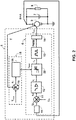
- the regulation device 5 of an alternator according to the invention focuses mainly on the problem of thermal stability of a "boosted" alternator.
- a solution proposed by the inventive entity is the use of the regulator 5 in order to control a current temperature T of the alternator using a sensor placed on the alternator ( more precisely, for example on the iron of a stator or on a rear bearing of the machine for measuring diode temperatures).
- this regulator 5 comprises a voltage control loop 6 making it possible to control a DC voltage B + A from a voltage setpoint U 0 of an on-board network of the vehicle, generally comprising a battery 7. and various equipment 8, powered by the alternator 9.
- the regulator 5 further comprises a temperature control loop 15.
- this temperature control loop 15 comprises a first temperature sensor supplying the current temperature T of the alternator 9.
- It can be a sensor external to regulator 5, placed on the stator iron or on the rear bearing to measure the temperature of the diodes, or alternatively, a sensor internal to regulator 5, measuring a junction temperature of the semiconductor switch 14 .
- a second comparator 18 with a predetermined maximum admissible temperature T max of the current temperature T generates a temperature error ⁇ T from which a control module 19 supplies the voltage control loop 6 with a maximum excitation percentage admissible r max making it possible to maintain the current temperature T of the alternator 9 at the value of the predetermined maximum admissible temperature T max .
- a slope of the maximum admissible excitation percentage r max as a function of the temperature error ⁇ T is about -5% / ° C, knowing that this slope will depend on the gains applied in the regulatory processing chain.
- the slope can be adapted in order to obtain a greater or lesser temperature regulation loop gain depending on a desired limited temperature precision.
- the maximum admissible excitation percentage r max supplied by the control module 19, 20, 21 is applied to a saturation module 22 inserted in series in the voltage control loop 6, between the first conditioning means 12 of the voltage error ⁇ V and the pulse width modulated signal generator 13.
- the resulting saturation function is shown on the Figure 3b .
- the output excitation percentage r o which is a function of the input excitation percentage r i is at most equal to the maximum admissible excitation percentage r max supplied by the control module 19, 20, 21.
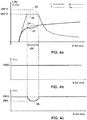
- FIGS. 4a, 4b and 4c show the effect of the temperature control loop 15, 16, 17 for an alternator 9 fitted with the regulation device 5 according to the invention by comparison with a standard alternator exhibiting a critical thermal equilibrium in a critical speed range ⁇ V without the regulation device 5 according to the invention, in the case where the current temperature T is stabilized in a quasi-stationary operating mode, or in a hypothesis where no account is taken of a current speed of rotation V.
- the current temperature T (thick dotted line 25) remains below 250 ° C.
- the regulation device 5 makes it possible to avoid this loss of flow I by taking into account the current speed of rotation V of the alternator 9 in the temperature control loop 15, 16, 17 in operating mode. dynamic.
- the Figure 6 establishes a comparison between the flow rate readings during the speed transition 28 when the temperature control loop 5, 16, 17 according to the invention is deactivated before the speed transition 28 (dotted line 29) and when it is active (solid line 30), on the assumption that the speed correction according to the invention is not applied.
- the behavior during the deceleration and acceleration phases of the vehicle is improved according to the invention by using the current speed of rotation V of the alternator 9 in addition to the current temperature T of the machine 9 in the loop d 'temperature control 15, 16, 17. This in order to anticipate the thermal state of the machine 9 and restore flow I as quickly as possible.
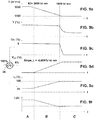
- the principle of the invention is to identify first the general form of a speed correction law for a given model of a family of alternators, then to store this general form in the regulation device 5.
- Slopes limiting the excitation r max / current speed of rotation V denoted Slope_L between the first and second speeds of rotation S1, S2, and Slope_H between the third and fourth speeds of rotation S3, S4, are also by approximation considered constant .
- Only the first and fourth speeds of rotation S1, S4 are variable and depend on an amplitude of the limitation, that is to say on the ambient temperature T amb .
- Each ambient temperature value T amb corresponds to a correction value providing a V cor correction as a function of the speed.
- the temperature control loop 16 comprises a control module 20 comprising speed correction means 32 in which the correction laws shown on the Figure 7 are stored.
- This control module 20 generates the speed correction V cor from the current speed of rotation V supplied by input means and from the ambient temperature T amb .
- r max 100% - C ⁇ T + V cor .
- this voltage servo loop 6 requires an input excitation duty cycle r i of 96% to maintain the desired voltage setpoint U 0 .
- the temperature control loop 16 transmits to the saturation module 22 that, in view of the current temperatures and rotation speed V of machine 9, 94% is the maximum applicable.
- the saturation module 22 will therefore ignore the 96% required by the voltage regulation 6 and will apply the 94% calculated by the temperature limitation 16.
- the direct consequence will be a measured voltage U b + lower than the voltage setpoint U 0 but a temperature controlled current T which will not exceed the limit temperature T max .
- the temperature control loop 17 comprises a control module 19, 21 comprising, in addition to speed correction means 32 in which the correction laws shown on the Figure 7 are stored, means 37 forcing from the maximum admissible excitation percentage r max to the maximum reference excitation percentage of 100%.
- This second embodiment incorporates the taking into account of the speed information presented previously and, moreover, temporarily authorizes a lifting of the excitation limitation during the phases of transition to speed 28. This in order to recover very quickly.
- a maximum flow rate I of the machine 9 as shown in Figure 12 (dotted line 38) by comparison with the flow rate curve I obtained with the first embodiment of the invention (solid line 35).
- ⁇ T A temporary increase in temperature, denoted ⁇ T, from the maximum admissible temperature T max up to a limit temperature T lim is authorized.
- a thermal limit is set at 240 ° C maximum on a stator temperature.
- the solid line curve 46 of the Figure 13 corresponds to the maximum admissible excitation percentage r max applied as a function of the current rotation speed V so as not to exceed 240 ° C on the stator.
- the dotted line curve 47 is an asymptotic plot of this same excitation limitation.
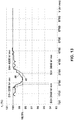
- the Figure 14 shows the temperature / flow rate behavior of the machine 9 as a function of the points stabilized in speed with the flow rate I (hollow lines 48, 49) and current temperature T (solid lines 50, 51) curves.
- the current temperature T (solid line 50) of the machine 9 according to the invention is controlled by reducing the flow rate I (hollow line 48).
- the curves in phantom 49, 51 are projections of the behavior of the machine 9 without the regulation device 5 according to the invention; the temperature of the alternator 9 would then be much too high (solid dotted line 51), with a maximum of 52 at 265 ° C., even if the flow rate is better (hollowed out dotted line 49).
- the various functional blocks of the regulation device 5, and in particular those of the control module 19, 20, 21, specified may be combined, split or replaced by other blocks so as to perform the same functions.
Landscapes
- Engineering & Computer Science (AREA)
- Power Engineering (AREA)
- Control Of Eletrric Generators (AREA)
Claims (10)
- Vorrichtung zur Regelung (5) einer Lichtmaschine (9) eines Kraftfahrzeugs, vom Typ derjenigen, die eine von der Lichtmaschine (9) erzeugte Gleichspannung (B+A) auf einen vorbestimmten Spannungssollwert (Uo) regeln, indem sie die Stärke eines Erregerstroms (IEXC) steuern, der in einem eine Erregerwicklung eines Rotors der Lichtmaschine (9) aufweisenden Erregerkreis fließt, und indem sie außerdem eine aktuelle Temperatur (T) der Lichtmaschine (9) unterhalb einer vorbestimmten zulässigen maximalen Temperatur (Tmax) halten, eine Spannungsregelschleife (6) umfassend, welche aufweist:- Mittel zur Erfassung (10) der Gleichspannung (B+A), die eine gemessene Spannung (Ub+) liefern;- einen ersten Komparator (11) zum Vergleich der gemessenen Spannung (Ub+) mit dem Spannungssollwert (U0), der einen Spannungsfehler (εV) erzeugt,und dadurch, dass sie außerdem eine Temperaturregelschleife (15, 16, 17) umfasst,
welche aufweist:- ein erstes Mittel zur Messung/Schätzung der Temperatur, das die aktuelle Temperatur (T) liefert;- einen zweiten Komparator (18), der einen Temperaturfehler (εT) zwischen der zulässigen maximalen Temperatur (Tmax) und der aktuellen Temperatur (T) erzeugt;- Eingangsmittel für eine aktuelle Drehzahl (V) der Lichtmaschine (9);dadurch gekennzeichnet, dass die Spannungsregelschleife (6) aufweist:- erste Konditionierungsmittel (12) für den Spannungsfehler (εV), die einen Prozentsatz der Eingangserregung (ri) liefern;- ein Sättigungsmodul (22), das in Abhängigkeit von dem Prozentsatz der Eingangserregung (ri) einen Prozentsatz der Ausgangserregung (ro) liefert, der auf einen zulässigen maximalen Prozentsatz der Erregung (rmax) begrenzt ist;- einen Generator (13) eines pulsweitenmodulierten (PWM) Signals, das ein Tastverhältnis aufweist, welches gleich dem Prozentsatz der Ausgangserregung (ro) ist;- einen von dem pulsweitenmodulierten (PWM) Signal angesteuerten Halbleiterschalter (14), der die Stromstärke (IEXC) steuert;und dadurch, dass die Temperaturregelschleife (15, 16, 17) ein Steuerungsmodul (19, 20, 21) aufweist, das den zulässigen maximalen Prozentsatz der Erregung (rmax) in Abhängigkeit von dem Temperaturfehler (εT) und von einer Drehzahlkorrektur (Vcor) liefert, die von Drehzahlkorrekturmitteln (32) gemäß einem vorbestimmten Korrekturgesetz in Abhängigkeit von der aktuellen Drehzahl (V) geliefert wird. - Vorrichtung zur Regelung (5) einer Lichtmaschine (9) eines Kraftfahrzeugs nach dem vorhergehenden Anspruch 1, dadurch gekennzeichnet, dass die Temperaturregelschleife (15, 16, 17) außerdem ein Mittel zur Berücksichtigung einer Umgebungstemperatur (Tamb) umfasst, und dadurch, dass das Korrekturgesetz mit der Umgebungstemperatur (Tamb) parametriert ist.
- Vorrichtung zur Regelung (5) einer Lichtmaschine (9) eines Kraftfahrzeugs nach dem vorhergehenden Anspruch 2, dadurch gekennzeichnet, dass das Korrekturgesetz eine als "wannenförmig" bezeichnete allgemeine Form hat und:- wenigstens einen negativen ersten Anstieg (Slope_L) zwischen einer ersten Drehzahl (S1), die in Abhängigkeit von der Umgebungstemperatur (Tamb) variabel ist, und einer vorbestimmten zweiten Drehzahl (S2) aufweist;- zwischen der zweiten Drehzahl (S2) und einer vorbestimmten dritten Drehzahl (S3) gleich null ist;- wenigstens einen positiven zweiten Anstieg (Slope_H) zwischen der dritten Drehzahl (S3) und einer vierten Drehzahl (S4), welche in Abhängigkeit von der Umgebungstemperatur variiert, aufweist.
- Vorrichtung zur Regelung (5) einer Lichtmaschine (9) eines Kraftfahrzeugs nach einem der vorhergehenden Ansprüche 1 bis 3, dadurch gekennzeichnet, dass das Steuerungsmodul (19, 20, 21) außerdem umfasst:- zweite Konditionierungsmittel (33) für den Temperaturfehler (εT), die einen Prozentsatz der thermischen Korrektur (CεT) liefern;- einen Summierkomparator (34), der den zulässigen maximalen Prozentsatz der Erregung (rmax) berechnet, indem er den Prozentsatz der thermischen Korrektur (CεT) von einer ersten Summe eines Referenz-Maximalprozentsatzes der Erregung und der Drehzahlkorrektur (Vcor) subtrahiert.
- Vorrichtung zur Regelung (5) einer Lichtmaschine (9) eines Kraftfahrzeugs nach dem vorhergehenden Anspruch 4, dadurch gekennzeichnet, dass das Steuerungsmodul (19, 20, 21) außerdem Mittel zum Erzwingen (37) der Regelung des zulässigen maximalen Prozentsatzes der Erregung (rmax) auf den Referenz-Maximalprozentsatz der Erregung (100 %) umfasst.
- Vorrichtung zur Regelung (5) einer Lichtmaschine (9) eines Kraftfahrzeugs nach dem vorhergehenden Anspruch 5, dadurch gekennzeichnet, dass die Erzwingungsmittel (37) durch einen Aktivierungsbefehl eines Motorsteuergerätes (39) des Fahrzeugs aktiviert werden.
- Vorrichtung zur Regelung (5) einer Lichtmaschine (9) eines Kraftfahrzeugs nach dem vorhergehenden Anspruch 6, dadurch gekennzeichnet, dass die Erzwingungsmittel (37) dann und nur dann aktiviert werden, wenn eine zeitliche Änderung (dV/dt) der aktuellen Drehzahl (V) dem absoluten Betrag nach größer als ein vorbestimmter Schwellenwert ist.
- Vorrichtung zur Regelung (5) einer Lichtmaschine (9) eines Kraftfahrzeugs nach dem vorhergehenden Anspruch 7, dadurch gekennzeichnet, dass die Erzwingungsmittel (37) so lange aktiviert bleiben, wie die aktuelle Temperatur (T) niedriger als eine Grenztemperatur (Tlim) ist, die gleich der um eine vorbestimmte Temperaturerhöhung (ΔT) erhöhten zulässigen maximalen Temperatur (Tmax) ist.
- Vorrichtung zur Regelung (5) einer Lichtmaschine (9) eines Kraftfahrzeugs nach dem vorhergehenden Anspruch 8, dadurch gekennzeichnet, dass die Erzwingungsmittel (37) von einem Timer (45) während einer vorbestimmten Dauer deaktiviert werden, wenn die aktuelle Temperatur (T) die Grenztemperatur (Tlim) erreicht.
- Lichtmaschine (9) eines Kraftfahrzeugs, welche eine Vorrichtung zur Regelung (5) nach einem der vorhergehenden Ansprüche 1 bis 9 umfasst.
Applications Claiming Priority (2)
| Application Number | Priority Date | Filing Date | Title |
|---|---|---|---|
| FR1652681A FR3049787B1 (fr) | 2016-03-29 | 2016-03-29 | Dispositif de regulation d'un alternateur de vehicule automobile et alternateur correspondant |
| PCT/FR2017/050438 WO2017168063A1 (fr) | 2016-03-29 | 2017-02-28 | Dispositif de regulation d'un alternateur de vehicule automobile et alternateur correspondant |
Publications (2)
| Publication Number | Publication Date |
|---|---|
| EP3437183A1 EP3437183A1 (de) | 2019-02-06 |
| EP3437183B1 true EP3437183B1 (de) | 2021-02-17 |
Family
ID=56119574
Family Applications (1)
| Application Number | Title | Priority Date | Filing Date |
|---|---|---|---|
| EP17713717.1A Active EP3437183B1 (de) | 2016-03-29 | 2017-02-28 | Vorrichtung zur regelung einer lichtmaschine eines kraftfahrzeugs und entsprechende lichtmaschine |
Country Status (6)
| Country | Link |
|---|---|
| US (1) | US20200335996A1 (de) |
| EP (1) | EP3437183B1 (de) |
| JP (1) | JP2019510461A (de) |
| CN (1) | CN108886335A (de) |
| FR (1) | FR3049787B1 (de) |
| WO (1) | WO2017168063A1 (de) |
Families Citing this family (1)
| Publication number | Priority date | Publication date | Assignee | Title |
|---|---|---|---|---|
| CN108471271B (zh) * | 2018-04-16 | 2021-03-23 | 成都极米科技股份有限公司 | 一种投影仪滑门电机控制方法及控制装置 |
Family Cites Families (8)
| Publication number | Priority date | Publication date | Assignee | Title |
|---|---|---|---|---|
| FR2420874A1 (fr) * | 1978-03-24 | 1979-10-19 | Sev Marchal | Regulateur associe a un alternateur notamment pour vehicule automobile |
| US4914361A (en) * | 1988-06-06 | 1990-04-03 | Hitachi, Ltd. | Method and apparatus for controlling the speed of moving body |
| JP4215025B2 (ja) * | 2005-04-25 | 2009-01-28 | 株式会社デンソー | 車両用発電制御装置 |
| US20070268003A1 (en) * | 2006-05-22 | 2007-11-22 | Kolomeitsev Sergei F | Systems and methods for maximizing the output of a vehicle alternator |
| FR2918225B1 (fr) * | 2007-06-28 | 2009-09-04 | Valeo Equip Electr Moteur | Machine electrique tournante destinee a etre montee sur un vehicule automobile |
| FR2938987B1 (fr) | 2008-11-24 | 2011-01-07 | Valeo Equip Electr Moteur | Procede de limitation de courant d'excitation maximum dans un systeme alterno-demarreur |
| FR2976422B1 (fr) * | 2011-06-08 | 2014-10-31 | Valeo Equip Electr Moteur | Procede de controle d'un couple resistant d'un alternateur de vehicule automobile, et systeme de mise en oeuvre de ce procede |
| FR2980319B1 (fr) * | 2011-09-20 | 2015-03-20 | Valeo Equip Electr Moteur | Procede et systeme de controle de la charge progressive d'un alternateur de vehicule automobile, et alternateur de vehicule automobile comprenant un tel systeme |
-
2016
- 2016-03-29 FR FR1652681A patent/FR3049787B1/fr not_active Expired - Fee Related
-
2017
- 2017-02-28 JP JP2018551467A patent/JP2019510461A/ja active Pending
- 2017-02-28 US US16/090,042 patent/US20200335996A1/en not_active Abandoned
- 2017-02-28 CN CN201780021625.8A patent/CN108886335A/zh active Pending
- 2017-02-28 EP EP17713717.1A patent/EP3437183B1/de active Active
- 2017-02-28 WO PCT/FR2017/050438 patent/WO2017168063A1/fr not_active Ceased
Non-Patent Citations (1)
| Title |
|---|
| None * |
Also Published As
| Publication number | Publication date |
|---|---|
| FR3049787A1 (fr) | 2017-10-06 |
| JP2019510461A (ja) | 2019-04-11 |
| FR3049787B1 (fr) | 2018-05-04 |
| CN108886335A (zh) | 2018-11-23 |
| WO2017168063A1 (fr) | 2017-10-05 |
| US20200335996A1 (en) | 2020-10-22 |
| EP3437183A1 (de) | 2019-02-06 |
Similar Documents
| Publication | Publication Date | Title |
|---|---|---|
| EP2719070B1 (de) | Verfahren zur steuerung des widerständigen drehmoments eines kraftfahrzeuggenerators und system zur durchführung dieses verfahrens | |
| FR2827249A1 (fr) | Dispositif de commande de direction | |
| FR2875652A1 (fr) | Procede et systeme pour commander la puissance a appliquer a des charges electriques | |
| FR2894735A1 (fr) | Generateur-moteur synchrone a enroulement de champ | |
| WO2015025089A1 (fr) | Procede de detection d'une deconnexion de batterie d'alimentation d'un vehicule automobile | |
| FR2979041A1 (fr) | Procede pour eviter les surtensions d'un reseau embarque d'un vehicule automobile | |
| WO2019122696A1 (fr) | Procédé de contrôle d'un convertisseur de courant continu dans un réseau de bord d'un véhicule automobile | |
| EP2259421B1 (de) | Verfahren zur Steuerung der progressiven Belastung einer Lichtmaschine eines Kraftfahrzeugs | |
| EP3867093B1 (de) | System zur vor-ort-diagnose der batterie eines elektrischen fahrrades | |
| EP3166220B1 (de) | Vorrichtung zur dynamischen begrenzung, und verfahren zur dynamischen begrenzung durch eine solche vorrichtung | |
| WO2013091826A1 (fr) | Commande d'une charge inductive avec mecanisme de reduction de courant sensible a la temperature | |
| EP4441862B1 (de) | Verfahren zur optimierten kühlung einer batterie eines elektro- oder hybridfahrzeugs | |
| WO2017168063A1 (fr) | Dispositif de regulation d'un alternateur de vehicule automobile et alternateur correspondant | |
| FR2983661A1 (fr) | Procede de gestion d'une machine electrique a excitation independante equipant un vehicule automobile | |
| EP3243271B1 (de) | Vorrichtung zur steuerung eines wechselstromgenerators eines kraftfahrzeugs und entsprechender wechselstromgenerator | |
| WO2010116108A1 (fr) | Dispositif de refroidissement pour véhicule automobile | |
| EP3095171B1 (de) | Verfahren zur steuerung eines als synchron gleichrichter einsetzbaren leistungselektronikmoduls, entsprechende steuerungsvorrichtung sowie diese vorrichtung enthaltende rotierende elektrische maschine in einem elektrischen fahrzeug | |
| EP2759054B1 (de) | Verfahren und system zur überwachung des ladungsfortschritts der lichtmaschine eines kraftfahrzeugs und kraftfahrzeug-lichtmaschine mit einem solchen system | |
| FR3026992A1 (fr) | Procede de pilotage d'un dispositif de charge de batterie, au regime moteur de ralenti | |
| EP3361087A1 (de) | System und verfahren zur repositionierung des rotors eines verbrennungsmotors | |
| EP4059131B1 (de) | Steuermodul und verfahren zum steuern des endes des motormodus für eine rotierende elektrische maschine | |
| FR3073692A1 (fr) | Alternateur demarreur pour un vehicule automobile | |
| FR3166500A1 (fr) | Procédé de contrôle d’un démarrage d’un moteur électrique, notamment un moteur d’entrainement d’un générateur d’un flux d’air | |
| FR2926414A1 (fr) | Procede d'optimisation d'un temps de reponse d'un alternateur sans perturbation d'un regime de moteur thermique et dispositif associe | |
| FR3019954A1 (fr) | Regulateur de tension d'un alternateur de vehicule automobile, incorporant une fonction de protection thermique de l'alternateur |
Legal Events
| Date | Code | Title | Description |
|---|---|---|---|
| STAA | Information on the status of an ep patent application or granted ep patent |
Free format text: STATUS: UNKNOWN |
|
| STAA | Information on the status of an ep patent application or granted ep patent |
Free format text: STATUS: THE INTERNATIONAL PUBLICATION HAS BEEN MADE |
|
| PUAI | Public reference made under article 153(3) epc to a published international application that has entered the european phase |
Free format text: ORIGINAL CODE: 0009012 |
|
| STAA | Information on the status of an ep patent application or granted ep patent |
Free format text: STATUS: REQUEST FOR EXAMINATION WAS MADE |
|
| 17P | Request for examination filed |
Effective date: 20180905 |
|
| AK | Designated contracting states |
Kind code of ref document: A1 Designated state(s): AL AT BE BG CH CY CZ DE DK EE ES FI FR GB GR HR HU IE IS IT LI LT LU LV MC MK MT NL NO PL PT RO RS SE SI SK SM TR |
|
| AX | Request for extension of the european patent |
Extension state: BA ME |
|
| DAV | Request for validation of the european patent (deleted) | ||
| DAX | Request for extension of the european patent (deleted) | ||
| STAA | Information on the status of an ep patent application or granted ep patent |
Free format text: STATUS: EXAMINATION IS IN PROGRESS |
|
| 17Q | First examination report despatched |
Effective date: 20200108 |
|
| GRAP | Despatch of communication of intention to grant a patent |
Free format text: ORIGINAL CODE: EPIDOSNIGR1 |
|
| STAA | Information on the status of an ep patent application or granted ep patent |
Free format text: STATUS: GRANT OF PATENT IS INTENDED |
|
| RIC1 | Information provided on ipc code assigned before grant |
Ipc: H02P 9/30 20060101AFI20200910BHEP Ipc: H02J 7/14 20060101ALI20200910BHEP Ipc: H02J 7/00 20060101ALI20200910BHEP |
|
| INTG | Intention to grant announced |
Effective date: 20200923 |
|
| GRAS | Grant fee paid |
Free format text: ORIGINAL CODE: EPIDOSNIGR3 |
|
| GRAA | (expected) grant |
Free format text: ORIGINAL CODE: 0009210 |
|
| STAA | Information on the status of an ep patent application or granted ep patent |
Free format text: STATUS: THE PATENT HAS BEEN GRANTED |
|
| AK | Designated contracting states |
Kind code of ref document: B1 Designated state(s): AL AT BE BG CH CY CZ DE DK EE ES FI FR GB GR HR HU IE IS IT LI LT LU LV MC MK MT NL NO PL PT RO RS SE SI SK SM TR |
|
| REG | Reference to a national code |
Ref country code: GB Ref legal event code: FG4D Free format text: NOT ENGLISH |
|
| REG | Reference to a national code |
Ref country code: CH Ref legal event code: EP |
|
| REG | Reference to a national code |
Ref country code: DE Ref legal event code: R096 Ref document number: 602017032634 Country of ref document: DE |
|
| REG | Reference to a national code |
Ref country code: AT Ref legal event code: REF Ref document number: 1362825 Country of ref document: AT Kind code of ref document: T Effective date: 20210315 |
|
| REG | Reference to a national code |
Ref country code: IE Ref legal event code: FG4D Free format text: LANGUAGE OF EP DOCUMENT: FRENCH |
|
| REG | Reference to a national code |
Ref country code: LT Ref legal event code: MG9D |
|
| REG | Reference to a national code |
Ref country code: NL Ref legal event code: MP Effective date: 20210217 |
|
| PG25 | Lapsed in a contracting state [announced via postgrant information from national office to epo] |
Ref country code: BG Free format text: LAPSE BECAUSE OF FAILURE TO SUBMIT A TRANSLATION OF THE DESCRIPTION OR TO PAY THE FEE WITHIN THE PRESCRIBED TIME-LIMIT Effective date: 20210517 Ref country code: LT Free format text: LAPSE BECAUSE OF FAILURE TO SUBMIT A TRANSLATION OF THE DESCRIPTION OR TO PAY THE FEE WITHIN THE PRESCRIBED TIME-LIMIT Effective date: 20210217 Ref country code: NO Free format text: LAPSE BECAUSE OF FAILURE TO SUBMIT A TRANSLATION OF THE DESCRIPTION OR TO PAY THE FEE WITHIN THE PRESCRIBED TIME-LIMIT Effective date: 20210517 Ref country code: PT Free format text: LAPSE BECAUSE OF FAILURE TO SUBMIT A TRANSLATION OF THE DESCRIPTION OR TO PAY THE FEE WITHIN THE PRESCRIBED TIME-LIMIT Effective date: 20210617 Ref country code: GR Free format text: LAPSE BECAUSE OF FAILURE TO SUBMIT A TRANSLATION OF THE DESCRIPTION OR TO PAY THE FEE WITHIN THE PRESCRIBED TIME-LIMIT Effective date: 20210518 Ref country code: FI Free format text: LAPSE BECAUSE OF FAILURE TO SUBMIT A TRANSLATION OF THE DESCRIPTION OR TO PAY THE FEE WITHIN THE PRESCRIBED TIME-LIMIT Effective date: 20210217 Ref country code: HR Free format text: LAPSE BECAUSE OF FAILURE TO SUBMIT A TRANSLATION OF THE DESCRIPTION OR TO PAY THE FEE WITHIN THE PRESCRIBED TIME-LIMIT Effective date: 20210217 |
|
| REG | Reference to a national code |
Ref country code: AT Ref legal event code: MK05 Ref document number: 1362825 Country of ref document: AT Kind code of ref document: T Effective date: 20210217 |
|
| PG25 | Lapsed in a contracting state [announced via postgrant information from national office to epo] |
Ref country code: SE Free format text: LAPSE BECAUSE OF FAILURE TO SUBMIT A TRANSLATION OF THE DESCRIPTION OR TO PAY THE FEE WITHIN THE PRESCRIBED TIME-LIMIT Effective date: 20210217 Ref country code: LV Free format text: LAPSE BECAUSE OF FAILURE TO SUBMIT A TRANSLATION OF THE DESCRIPTION OR TO PAY THE FEE WITHIN THE PRESCRIBED TIME-LIMIT Effective date: 20210217 Ref country code: RS Free format text: LAPSE BECAUSE OF FAILURE TO SUBMIT A TRANSLATION OF THE DESCRIPTION OR TO PAY THE FEE WITHIN THE PRESCRIBED TIME-LIMIT Effective date: 20210217 Ref country code: PL Free format text: LAPSE BECAUSE OF FAILURE TO SUBMIT A TRANSLATION OF THE DESCRIPTION OR TO PAY THE FEE WITHIN THE PRESCRIBED TIME-LIMIT Effective date: 20210217 Ref country code: NL Free format text: LAPSE BECAUSE OF FAILURE TO SUBMIT A TRANSLATION OF THE DESCRIPTION OR TO PAY THE FEE WITHIN THE PRESCRIBED TIME-LIMIT Effective date: 20210217 |
|
| PG25 | Lapsed in a contracting state [announced via postgrant information from national office to epo] |
Ref country code: IS Free format text: LAPSE BECAUSE OF FAILURE TO SUBMIT A TRANSLATION OF THE DESCRIPTION OR TO PAY THE FEE WITHIN THE PRESCRIBED TIME-LIMIT Effective date: 20210617 |
|
| REG | Reference to a national code |
Ref country code: BE Ref legal event code: MM Effective date: 20210228 |
|
| PG25 | Lapsed in a contracting state [announced via postgrant information from national office to epo] |
Ref country code: AT Free format text: LAPSE BECAUSE OF FAILURE TO SUBMIT A TRANSLATION OF THE DESCRIPTION OR TO PAY THE FEE WITHIN THE PRESCRIBED TIME-LIMIT Effective date: 20210217 Ref country code: CH Free format text: LAPSE BECAUSE OF NON-PAYMENT OF DUE FEES Effective date: 20210228 Ref country code: SM Free format text: LAPSE BECAUSE OF FAILURE TO SUBMIT A TRANSLATION OF THE DESCRIPTION OR TO PAY THE FEE WITHIN THE PRESCRIBED TIME-LIMIT Effective date: 20210217 Ref country code: LI Free format text: LAPSE BECAUSE OF NON-PAYMENT OF DUE FEES Effective date: 20210228 Ref country code: LU Free format text: LAPSE BECAUSE OF NON-PAYMENT OF DUE FEES Effective date: 20210228 Ref country code: EE Free format text: LAPSE BECAUSE OF FAILURE TO SUBMIT A TRANSLATION OF THE DESCRIPTION OR TO PAY THE FEE WITHIN THE PRESCRIBED TIME-LIMIT Effective date: 20210217 Ref country code: CZ Free format text: LAPSE BECAUSE OF FAILURE TO SUBMIT A TRANSLATION OF THE DESCRIPTION OR TO PAY THE FEE WITHIN THE PRESCRIBED TIME-LIMIT Effective date: 20210217 |
|
| REG | Reference to a national code |
Ref country code: DE Ref legal event code: R097 Ref document number: 602017032634 Country of ref document: DE |
|
| PG25 | Lapsed in a contracting state [announced via postgrant information from national office to epo] |
Ref country code: SK Free format text: LAPSE BECAUSE OF FAILURE TO SUBMIT A TRANSLATION OF THE DESCRIPTION OR TO PAY THE FEE WITHIN THE PRESCRIBED TIME-LIMIT Effective date: 20210217 Ref country code: DK Free format text: LAPSE BECAUSE OF FAILURE TO SUBMIT A TRANSLATION OF THE DESCRIPTION OR TO PAY THE FEE WITHIN THE PRESCRIBED TIME-LIMIT Effective date: 20210217 Ref country code: RO Free format text: LAPSE BECAUSE OF FAILURE TO SUBMIT A TRANSLATION OF THE DESCRIPTION OR TO PAY THE FEE WITHIN THE PRESCRIBED TIME-LIMIT Effective date: 20210217 Ref country code: MC Free format text: LAPSE BECAUSE OF FAILURE TO SUBMIT A TRANSLATION OF THE DESCRIPTION OR TO PAY THE FEE WITHIN THE PRESCRIBED TIME-LIMIT Effective date: 20210217 |
|
| PLBE | No opposition filed within time limit |
Free format text: ORIGINAL CODE: 0009261 |
|
| STAA | Information on the status of an ep patent application or granted ep patent |
Free format text: STATUS: NO OPPOSITION FILED WITHIN TIME LIMIT |
|
| 26N | No opposition filed |
Effective date: 20211118 |
|
| GBPC | Gb: european patent ceased through non-payment of renewal fee |
Effective date: 20210517 |
|
| PG25 | Lapsed in a contracting state [announced via postgrant information from national office to epo] |
Ref country code: AL Free format text: LAPSE BECAUSE OF FAILURE TO SUBMIT A TRANSLATION OF THE DESCRIPTION OR TO PAY THE FEE WITHIN THE PRESCRIBED TIME-LIMIT Effective date: 20210217 Ref country code: ES Free format text: LAPSE BECAUSE OF FAILURE TO SUBMIT A TRANSLATION OF THE DESCRIPTION OR TO PAY THE FEE WITHIN THE PRESCRIBED TIME-LIMIT Effective date: 20210217 Ref country code: IE Free format text: LAPSE BECAUSE OF NON-PAYMENT OF DUE FEES Effective date: 20210228 |
|
| PG25 | Lapsed in a contracting state [announced via postgrant information from national office to epo] |
Ref country code: SI Free format text: LAPSE BECAUSE OF FAILURE TO SUBMIT A TRANSLATION OF THE DESCRIPTION OR TO PAY THE FEE WITHIN THE PRESCRIBED TIME-LIMIT Effective date: 20210217 |
|
| PG25 | Lapsed in a contracting state [announced via postgrant information from national office to epo] |
Ref country code: IT Free format text: LAPSE BECAUSE OF FAILURE TO SUBMIT A TRANSLATION OF THE DESCRIPTION OR TO PAY THE FEE WITHIN THE PRESCRIBED TIME-LIMIT Effective date: 20210217 Ref country code: GB Free format text: LAPSE BECAUSE OF NON-PAYMENT OF DUE FEES Effective date: 20210517 |
|
| PG25 | Lapsed in a contracting state [announced via postgrant information from national office to epo] |
Ref country code: IS Free format text: LAPSE BECAUSE OF FAILURE TO SUBMIT A TRANSLATION OF THE DESCRIPTION OR TO PAY THE FEE WITHIN THE PRESCRIBED TIME-LIMIT Effective date: 20210617 |
|
| PG25 | Lapsed in a contracting state [announced via postgrant information from national office to epo] |
Ref country code: BE Free format text: LAPSE BECAUSE OF NON-PAYMENT OF DUE FEES Effective date: 20210228 |
|
| PG25 | Lapsed in a contracting state [announced via postgrant information from national office to epo] |
Ref country code: CY Free format text: LAPSE BECAUSE OF FAILURE TO SUBMIT A TRANSLATION OF THE DESCRIPTION OR TO PAY THE FEE WITHIN THE PRESCRIBED TIME-LIMIT Effective date: 20210217 |
|
| P01 | Opt-out of the competence of the unified patent court (upc) registered |
Effective date: 20230528 |
|
| PG25 | Lapsed in a contracting state [announced via postgrant information from national office to epo] |
Ref country code: HU Free format text: LAPSE BECAUSE OF FAILURE TO SUBMIT A TRANSLATION OF THE DESCRIPTION OR TO PAY THE FEE WITHIN THE PRESCRIBED TIME-LIMIT; INVALID AB INITIO Effective date: 20170228 |
|
| PG25 | Lapsed in a contracting state [announced via postgrant information from national office to epo] |
Ref country code: MK Free format text: LAPSE BECAUSE OF FAILURE TO SUBMIT A TRANSLATION OF THE DESCRIPTION OR TO PAY THE FEE WITHIN THE PRESCRIBED TIME-LIMIT Effective date: 20210217 |
|
| PG25 | Lapsed in a contracting state [announced via postgrant information from national office to epo] |
Ref country code: TR Free format text: LAPSE BECAUSE OF FAILURE TO SUBMIT A TRANSLATION OF THE DESCRIPTION OR TO PAY THE FEE WITHIN THE PRESCRIBED TIME-LIMIT Effective date: 20210217 |
|
| PG25 | Lapsed in a contracting state [announced via postgrant information from national office to epo] |
Ref country code: MT Free format text: LAPSE BECAUSE OF FAILURE TO SUBMIT A TRANSLATION OF THE DESCRIPTION OR TO PAY THE FEE WITHIN THE PRESCRIBED TIME-LIMIT Effective date: 20210217 |
|
| PGFP | Annual fee paid to national office [announced via postgrant information from national office to epo] |
Ref country code: DE Payment date: 20250212 Year of fee payment: 9 |
|
| PGFP | Annual fee paid to national office [announced via postgrant information from national office to epo] |
Ref country code: FR Payment date: 20250225 Year of fee payment: 9 |