EP3437388B1 - Commande de synchronisation de transmission en liaison montante - Google Patents
Commande de synchronisation de transmission en liaison montante Download PDFInfo
- Publication number
- EP3437388B1 EP3437388B1 EP17714185.0A EP17714185A EP3437388B1 EP 3437388 B1 EP3437388 B1 EP 3437388B1 EP 17714185 A EP17714185 A EP 17714185A EP 3437388 B1 EP3437388 B1 EP 3437388B1
- Authority
- EP
- European Patent Office
- Prior art keywords
- uplink
- wireless communication
- timing
- communication device
- repetition period
- Prior art date
- Legal status (The legal status is an assumption and is not a legal conclusion. Google has not performed a legal analysis and makes no representation as to the accuracy of the status listed.)
- Active
Links
Images



Classifications
-
- H—ELECTRICITY
- H04—ELECTRIC COMMUNICATION TECHNIQUE
- H04W—WIRELESS COMMUNICATION NETWORKS
- H04W56/00—Synchronisation arrangements
- H04W56/004—Synchronisation arrangements compensating for timing error of reception due to propagation delay
- H04W56/0045—Synchronisation arrangements compensating for timing error of reception due to propagation delay compensating for timing error by altering transmission time
-
- H—ELECTRICITY
- H04—ELECTRIC COMMUNICATION TECHNIQUE
- H04W—WIRELESS COMMUNICATION NETWORKS
- H04W4/00—Services specially adapted for wireless communication networks; Facilities therefor
- H04W4/70—Services for machine-to-machine communication [M2M] or machine type communication [MTC]
-
- H—ELECTRICITY
- H04—ELECTRIC COMMUNICATION TECHNIQUE
- H04W—WIRELESS COMMUNICATION NETWORKS
- H04W72/00—Local resource management
- H04W72/04—Wireless resource allocation
- H04W72/044—Wireless resource allocation based on the type of the allocated resource
- H04W72/0446—Resources in time domain, e.g. slots or frames
-
- H—ELECTRICITY
- H04—ELECTRIC COMMUNICATION TECHNIQUE
- H04W—WIRELESS COMMUNICATION NETWORKS
- H04W72/00—Local resource management
- H04W72/20—Control channels or signalling for resource management
- H04W72/21—Control channels or signalling for resource management in the uplink direction of a wireless link, i.e. towards the network
-
- H—ELECTRICITY
- H04—ELECTRIC COMMUNICATION TECHNIQUE
- H04W—WIRELESS COMMUNICATION NETWORKS
- H04W72/00—Local resource management
- H04W72/20—Control channels or signalling for resource management
- H04W72/23—Control channels or signalling for resource management in the downlink direction of a wireless link, i.e. towards a terminal
Definitions
- Embodiments of the disclosure generally relate to the field of wireless communication, and more specifically, to uplink transmission timing control in a wireless communication device, such as an Evolved Machine-type communication (eMTC) device and/or a Narrowband Internet-of-things (NB-IoT) device.
- a wireless communication device such as an Evolved Machine-type communication (eMTC) device and/or a Narrowband Internet-of-things (NB-IoT) device.
- eMTC Evolved Machine-type communication
- NB-IoT Narrowband Internet-of-things
- LTE Long Term Evolution of UMTS
- the timing advance control loop latency becomes longer than in conventional LTE system operation. This is because the uplink reference signals from multiple subframes may have to be averaged or filtered by the network node, to determine channel estimates from which the misalignment with respect to the desirable signal reception time can be determined. Additionally, when a half-duplex frequency-division duplexing (HD-FDD) configuration is used by the wireless communication device (e.g., in HD-FDD eMTC and/or NB-loT devices), the network node has fewer opportunities to send TACs to the device. Particularly, during an uplink transmission period, the wireless communication device operating in HD-FDD configuration will not listen to the downlink and therefore is out of reach for the network node until tuning back to a downlink reception period.
- HD-FDD half-duplex frequency-division duplexing
- a wireless communication system comprises a wireless communication device configured to operate in a coverage enhancement mode comprising a repetitive transmission of a first uplink signal during a first repetition period, and a network node serving the wireless communication device.
- the network node comprises a transmitting unit for transmitting a reference signal to the wireless communication device.
- the wireless communication device comprises a first determining unit configured to determine a change in a downlink timing based on the reference signal, a second determining unit configured to determine whether the first repetition period is ongoing and an adjusting unit configured to, in response to the change in the downlink timing and the first repetition period being ongoing, perform an adjustment of an uplink transmission timing of the first uplink signal outside the first repetition period.
- one or more of the objects are achieved by a method for an uplink transmission timing adjustment in a wireless communication device served by a network node and configured to operate in a coverage enhancement mode.
- the coverage enhancement mode comprises a repetitive transmission of a first uplink signal during a first repetition period.
- the method comprises determining a change in a downlink timing, determining whether the first repetition period is ongoing and in response to the change in the downlink timing and the first repetition period being ongoing, performing an adjustment of an uplink transmission timing of the first uplink signal outside the first repetition period.
- one or more of the objects are achieved by a method for an uplink transmission timing adjustment in a wireless communication device served by a network node and configured to operate in a coverage enhancement mode.
- the coverage enhancement mode comprises repetitive transmissions of multiple uplink signals within respective repetition periods.
- the method comprises aligning the respective repetition periods by shifting in time at least one of start or end points of the respective repetition periods according to a predetermined rule, such that an overlap time of the respective repetition periods is maximized or single transmission of the multiple uplink signals is minimized.
- a wireless communication device served by a network node and configured to operate in a coverage enhancement mode.
- the coverage enhancement mode comprises a repetitive transmission of a first uplink signal during a first repetition period.
- the wireless communication device comprises a first determining unit configured to determine a change in a downlink timing, a second determining unit configured to determine whether the first repetition period is ongoing, and an adjusting unit configured to, in response to the change in the downlink timing and the first repetition period being ongoing, perform an adjustment of an uplink transmission timing of the first uplink signal outside the first repetition period.
- one or more of the objects are achieved by a method for enhancing an uplink transmission timing adjustment procedure for a wireless communication device.
- the method comprises determining that the wireless communication device is to be configured to transmit at least two uplink signals over at least partly overlapping repetition periods, and enabling the wireless communication device to align the respective repetition periods of the at least two uplink signals.
- a network node for enhancing an uplink transmission timing adjustment procedure for a wireless communication device.
- the network node comprises a determining unit configured to determine that the wireless communication device is to be configured to transmit at least two uplink signals over at least partly overlapping repetition periods, and an enabling unit configured to enable the wireless communication device to align the respective repetition periods of the at least two uplink signals.
- a wireless communication device served by a network node and configured to operate in a coverage enhancement mode.
- the wireless communication device comprises a non-transitory machine-readable storage medium having stored instructions therein, and a processor communicatively coupled to the non-transitory machine-readable storage medium.
- the processor is configured to execute the instructions stored in the non-transitory machine-readable storage medium to perform a method in the wireless communication device.
- a network node for enhancing an uplink transmission timing adjustment procedure for a wireless communication device.
- the network node comprises a non-transitory machine-readable storage medium having stored instructions therein, and a processor communicatively coupled to the non-transitory machine-readable storage medium.
- the processor is configured to execute the instructions stored in the non-transitory machine-readable storage medium to perform a method in the network node.
- one or more of the objects are achieved by a method in a UE served by a serving cell.
- the method comprises the steps of determining that downlink timing of a reference signal received at the UE from the serving cell has changed with respect to a reference time by a certain amount; determining whether the UE is configured to transmit a first uplink signal with a certain repetition over a time period, TO; and determining an adjustment time resource in which the uplink transmit timing for transmitting the first signal is adjusted, which adjustment time resource is determined in response to the determined change in the downlink reception timing and depends on whether the UE is configured with the first signal with or without repetitions (e.g., adjustment time resource such as a subframe occurs immediately after T0 if repetition is configured).
- one or more of the objects are achieved by a method in a UE served by a serving cell.
- the method comprises the steps of: determining that downlink timing of a reference signal received at the UE from the serving cell has changed with respect to a reference time by a certain amount; determining that the UE is configured to transmit at least two uplink signals over at least partly overlapping repetition periods, comprising a first uplink signal with a certain repetition over a time period, T1 and a second uplink signal with a certain repetition over a time period, T2; and determining an adjustment time resource in which the uplink transmit timing for transmitting at least one of the first signal and the second signal is adjusted, which adjustment time resource is determined in response to the determined change in the downlink reception timing and further depends on the relations between the starting times of T1 and T2 and/or terminating times of T1 and T2 (e.g., adjustment time resource such as a subframe occurs immediately after T2 if T2 terminates after T1).
- one or more of the objects are achieved by a method in a network node serving a UE.
- the method comprises the steps of: determining that downlink timing of a reference signal received at the UE from the serving cell has changed with respect to a reference time by a certain amount; determining that the UE is to be configured to transmit at least two uplink signals over at least partly overlapping repetition periods comprising a first uplink signal with a certain repetition over a time period, T1 and a second uplink signal with a certain repetition over a time period, T2; and configuring the UE with information for enabling the UE to transmit the first uplink signal and the second uplink signal such that T1 and T2 are related by a certain relation, e.g., one or more of: T1 and T2 start at the same time, e.g., in the same time resource such as in the same subframe, T1 and T2 end at the same time, e.g., in the same time resource such as in the same subframe, T1
- one or more of the objects are achieved by a computer-readable medium carrying instructions, which, when executed by a processor, causes the processor to carry out one or more of the above methods.
- one or more of the objects are achieved by a computer-program accessible by a processor of a wireless communication device or a network node, which when executed by the processor, causes the processor to carry out one or more of the above methods.
- One or more of these aspects can facilitate accumulation and filtering of repeated uplink transmissions at the network node side, and thus improve the uplink throughput of the wireless communication system.
- circuit may include either a single component or a plurality of components, which are either active and/or passive and are connected or otherwise coupled together to provide the described function.
- references in the specification to "one embodiment,” “an embodiment,” “an example embodiment,”, etc., indicate that the embodiment described may include a particular feature, structure, or characteristic, but every embodiment may not necessarily include the particular feature, structure, or characteristic. Moreover, such phrases are not necessarily referring to the same embodiment. Further, when a particular feature, structure, or characteristic is described in connection with an embodiment, it is submitted that it is within the knowledge of one skilled in the art to affect such feature, structure, or characteristic in connection with other embodiments whether or not explicitly described.
- Bracketed text and blocks with dashed borders may be used herein to illustrate optional operations that add additional features to embodiments of the disclosure. However, such notation should not be taken to mean that these are the only options or optional operations, and/or that blocks with solid borders are not optional in certain embodiments of the disclosure.
- Coupled is used to indicate that two or more elements, which may or may not be in direct physical or electrical contact with each other, co-operate or interact with each other.
- Connected is used to indicate the establishment of communication between two or more elements that are coupled with each other.
- eMTC features specified in 3GPP technical contributions identified by 3GPP as contribution documents 3GPP RP-152024 and 3GPP R1-157926 include a low-complexity user equipment (UE) category called UE category M1 (or Cat-M1 for short) and coverage enhancement techniques, CE modes A and B, that can be used together with UE category M1 or any other LTE UE category.
- UE category M1 or Cat-M1 for short
- CE modes A and B coverage enhancement techniques
- All eMTC features for both Cat-M1 and CE modes A and B, as defined in 3GPP TS 36.133 V12.7.0, Section 7.1.2 , operate using a reduced maximum channel bandwidth compared to normal LTE.
- the maximum channel bandwidth in eMTC is 1.4 MHz, whereas it is up to 20 MHz in normal LTE.
- the eMTC UEs are still able to operate within the larger LTE system bandwidth, generally without problems.
- the main difference compared to normal LTE UEs is that the eMTCs can only be scheduled with 6 physical resource blocks (PRBs) at a time, where each of these PRBs has a bandwidth of 180 kHz.
- PRBs physical resource blocks
- CE modes A and B the coverage of physical channels is enhanced through various coverage enhancement techniques, the most important being repetition or retransmission.
- the objective of the Narrow Band Internet-of-things (NB-IoT) initiative of the 3GPP is to specify a radio access for cellular internet of things (loT), based to a great extent on a non-backward-compatible variant of E-UTRA (LTE), that addresses improved indoor coverage, support for massive number of low throughput devices, low delay sensitivity, ultra-low device cost, low device power consumption and (optimized) network architecture.
- LTE non-backward-compatible variant of E-UTRA
- the NB-loT carrier BW (Bw2) is 200 KHz.
- Examples of the operating bandwidth (Bw1) of LTE, in contrast, are 1.4 MHz, 3 MHz, 5 MHz, 10 MHz, 15 MHz, 20 MHz, etc.
- NB-loT radio access supports three different modes of operation:
- the downlink transmission is based on Orthogonal Frequency-Division Multiplexing (OFDM), with 15 kHz subcarrier spacing for all the scenarios: standalone, guard-band, and in-band.
- OFDM Orthogonal Frequency-Division Multiplexing
- SC-FDMA single-carrier Frequency-Division Multiple Access
- NB-loT supports both master information broadcast and system information broadcast which are carried by different physical channels.
- NB-loT UE For in-band operation, it is possible for NB-loT UE to decode NB-PBCH (also referred to as NPBCH) without knowing the legacy PRB index.
- NB-loT supports both downlink physical control channel (NB-PDCCH, also referred to as NPDCCH) and downlink physical shared channel (PDSCH, also referred to as NPDSCH).
- NB-PDCCH also referred to as NPDCCH
- PDSCH downlink physical shared channel
- NB-SSS also referred to as NSSS
- NB-MIB carried on NB-PBCH, also referred to as NPBCH
- downlink signals perhaps other downlink signals.
- NB-PSS primary synchronization signal
- NB-SSS secondary synchronization signal
- the uplink (UL) and downlink (DL) transmissions take place on different paired carrier frequencies but not simultaneously in time in the same cell. This means that the uplink and downlink transmissions take place in different time resources. Examples of a time resource are symbols, time slots, subframes, transmission time intervals (TTIs), interleaving times, etc.
- uplink and downlink e.g., subframes
- TTIs transmission time intervals
- uplink and downlink do not overlap in time.
- the number and location of subframes used for downlink, uplink, or unused subframes can vary on a frame-to-frame basis, or on a basis of multiple frames.
- subframes # 9, #0, #4 and #5 may be used for downlink, while subframes # 2 and #7 are used for uplink transmission. But in another frame (say frame#2), subframes #0 and #5 are used for downlink and subframes # 2, #3, #5, #7 and #8 are used for uplink transmission.
- the uplink transmissions from multiple user equipments (UEs) in LTE need to be time aligned at a receiver, such as a base station, e.g., an LTE eNode B or the like.
- a receiver such as a base station, e.g., an LTE eNode B or the like.
- the transmit timing of those UEs that are under the control of the same eNode B should be adjusted to ensure that their received signals arrive at the eNode B receiver at approximately the same time. More specifically, their received signals should arrive well within the cyclic prefix (CP), where the normal CP length is about 4.7 ⁇ s.
- CP cyclic prefix
- DFT Discrete Fourier Transform
- FFT Fast Four
- the uplink timing advance is maintained by the eNode B through timing advance commands, also referred to as timing alignment commands, sent to the UE based on measurements on uplink transmissions from that UE. For example, the eNode B measures a two-way propagation delay or round-trip time for each UE, to determine the value of the TA required for that UE.
- the corresponding adjustment of the uplink transmission timing is applied by the UE from the beginning of subframe n+6.
- NTA is defined above in section "Alignment of E-UTRA TDD measurement gaps with particular subframe offsets".
- TA timing advance command
- Timing advance updates are signaled by the evolved Node B (eNB) to the UE in MAC PDUs.
- eNB evolved Node B
- the path loss between loT device and the base station can be very large in some scenarios, such as when the device is used as a sensor or metering device located in a remote location such as in the basement of the building. In such scenarios, the reception of the signal from base station may be very challenging. For example, the path loss can be worse by 20 dB, compared to normal operation. In order to cope with such challenges, the coverage in uplink and/or in downlink has to be substantially enhanced with respect to the normal coverage (also referred to as legacy coverage). This is realized by employing one or several advanced techniques in the UE and/or in the radio network node for enhancing the coverage.
- Some non-limiting examples of such advanced techniques include transmit power boosting, repetition of transmitted signal, applying additional redundancy to the transmitted signal, use of advanced/enhanced receiver architectures, etc.
- the loT radio access is regarded to be operating in 'coverage enhancing mode' or coverage extending mode.
- the maximum number of repetitions for PDSCH and PUSCH, respectively, for coverage enhancement modes A and B are given by cell-specific broadcasted parameters:
- the exact number of repetitions to use by a particular wireless communication device is signaled dynamically via the downlink control information (DCI), which is carried over the downlink control channel M-PDCCH.
- DCI downlink control information
- This channel may be repeated according to a specific repetition number individually configured for each wireless communication device:
- a low complexity UE may also be capable of supporting enhanced coverage mode of operation.
- the coverage level of the UE with regard to a cell may be expressed in terms of a signal level, such as signal quality, signal strength or path loss, with regard to that cell.
- Fig. 1 is a simplified block diagram of an exemplary wireless communication system 100 in which one or more embodiments described herein may be implemented.
- the wireless communication system 100 may be described below with reference to LTE systems, and using LTE terminology. However, the techniques and apparatus described in the context of system 100 may be applicable, with suitable modifications, to any RAT or multi-RAT systems where the UE receives and/or transmit signals (e.g., data), e.g., LTE FDD/TDD, WCDMA/HSPA, GSM/GERAN, Wi Fi, WLAN, CDMA2000, NR, etc.
- the network node could be configured for operation using more than one cell, e.g., using PCell, SCell, PSCell.
- the wireless communication system 100 may include at least one network node 120 and at least one wireless communication device 110 served by the network node 120.
- the number of network nodes 120 and/or the wireless communication devices 110 as shown in Fig. 1 is only illustrative, and not limiting.
- the network node 120 may be referred to a radio base station, sometimes also referred to in the art as a macro base station, a node B, or B-node, an eNodeB (eNB), and may be sometimes also referred to in the art as a micro/femto/pico base stations, a micro/femto/pico node B, or micro/femto/pico B-node, a micro/femto/pico eNodeB (eNB). Further, the network node 120 could also be any other device in the wireless network, such as a WLAN access point, that could enable similar contributions to the D2D communications herein as an eNodeB does.
- a radio base station sometimes also referred to in the art as a macro base station, a node B, or B-node, an eNodeB (eNB)
- eNB eNodeB
- the network node 120 could also be any other device in the wireless network, such as
- the wireless communication devices 110 may be served by cells, and the numbers served by different cells need not be identical.
- the term "wireless communication device” as used herein may indicate all forms of devices enabled to communicate via a communication network, such as mobile telephones ("cellular" telephones) and laptops with mobile termination, and thus can be, for example, portable, pocket, hand-held devices, such as mobile phones, smart phones, personal digital assistants (PDA); computer-included devices, such as desktops, laptops; vehicles, or other devices, such as meters, household appliances, medical appliances, multimedia devices, etc., which communicate voice and/or data with a radio access network.
- cellular mobile telephones
- PDA personal digital assistants
- computer-included devices such as desktops, laptops
- vehicles, or other devices such as meters, household appliances, medical appliances, multimedia devices, etc., which communicate voice and/or data with a radio access network.
- Fig. 3a is a simplified block diagram of a wireless communication device 110 according to an exemplary embodiment.
- the wireless communication device 110 may comprise, but not be limited to, an adjusting unit 320, and first, second and third determining units 320, 330 and 340 operatively coupled with each other.
- Fig. 5a is a simplified block diagram of a network node 120 according to an exemplary embodiment.
- the network node 120 may comprise, but not limited to, a determining unit 510, an enabling unit 520 and a transmitting unit 530 operatively coupled with each other.
- the network node 120 transmits a reference signal to the wireless communication device 110 via the transmitting unit 530, and the wireless communication device 110 may be configured to operate in an enhanced coverage mode comprising a repetitive transmission of an uplink signal during a repetition period, and to determine a change in a downlink timing from the reference signal via the first determining unit 310.
- the wireless communication device 110 may determine that downlink timing of the received reference signal from the serving cell has changed with respect to a reference time by a certain amount.
- the wireless communication device 110 may further be configured to determine whether the repetition period is ongoing via the second determining unit 330.
- the wireless communication device 110 may be configured to perform an adjustment of an uplink transmission timing of the uplink signal outside the repetition period via the adjusting unit 320.
- the network node 120 may determine, via the determining unit 510, that the wireless communication device 110 is to be configured to transmit at least two uplink signals with at least partly overlapped repetition periods comprising as a first uplink signal with a certain repetition over a time period T1 and a second uplink signal with a certain repetition over a time period T2, and thus enable, via the enabling unit 520, the wireless communication device 110 to align the repetition periods T1 and T2 according to a predetermined rule, such that an overlap time of the repetition periods T1 and T2 can be maximized or single transmission of the at least two uplink signals can be minimized.
- the network node 120 may configure the wireless communication device 110 with information for enabling the wireless communication device 110 to transmit the first uplink signal and the second uplink signal such that the repetition periods T1 and T2 are related by a certain relation, e.g., one or more of:
- the third determining unit 340 in the wireless communication device 110 may be configured to determine whether the repetition period is longer than one radio resource time unit based on one of: downlink control information (DCI) transmitted by the network node, wherein the DCI contains explicit or implicit information on a number of repetitions to use for the repetitive transmission of the first uplink signals, and radio resource control (RRC) configuration provided by the network node, wherein the RRC configuration contains a number of resources for the wireless communication device in a radio resource time unit, and wherein the number of resources explicitly or implicitly indicates the number of repetitions.
- DCI downlink control information
- RRC radio resource control
- the timing adjustment behavior of a wireless communication device compliant to the EUTRAN standard is governed by several rules specified in 3GPP 36.133 V12.9.0, section 7.1.2. According to these rules, for non-initial transmission and LTE bandwidth 1.4MHz (minimum sample rate 1.92MS/s):
- a first transmission in HD-FDD uplink burst of repetitions is to be considered as an initial transmission or not. Since the wireless communication device has not been in a DRX inactivity period prior to the onset of the uplink transmission, and the HD-FDD uplink burst is not a transmission of PRACH, the first transmission in an uplink burst may be considered a non-initial transmission. In such an implementation, any serving cell timing drift that has been detected during the downlink repetition period of the HD-FDD would be corrected during the uplink repetition period, and would be corrected gradually according to the existing rules for non-initial transmissions as summarized above.
- Gradual uplink timing changes during an uplink repetition period may be particularly challenging for the network node.
- the gradual timing change results in a gradual change of (linear) phase of the received signal, and hence changes the perceived radio channel.
- Accumulation or filtering of channel estimates over the time domain may result in distorted channel estimates, and accumulation of the message part of the signal may likewise lead to a distorted accumulated message.
- the distortion in turn results in a degraded decoder performance in the network node.
- the wireless communication device may acquire new information on the downlink cell timing during an ongoing uplink transmission burst. If the wireless communication device changes the uplink timing during the repetition period, the gradual change in uplink timing will introduce distortion of the accumulated or filtered signals on the network node receiver side as described above, with degraded decoder performance in the network node.
- the frequency drift of the wireless communication device is relatively small, since first, the device has more opportunities to synchronize with the downlink carrier, and secondly, the uplink transmission power amplifier (PA) is operating during the time the UE synchronizes to the downlink carrier, leading to less fluctuations in temperature and hence a more stable frequency reference from the crystal oscillator.
- PA uplink transmission power amplifier
- NB-IoT radio access it is foreseen that it will be sufficient to use a downlink sample rate of about 240kS/s, since the NB-loT downlink system bandwidth is limited to 200 kHz, i.e., considerably less than for eMTC.
- the lower sample rate potentially leads to more dramatic serving cell downlink timing adjustments, since a one sample adjustment corresponds to ⁇ 128 TS ( ⁇ 4.2 ⁇ s).
- For an adjustment of downlink timing of one sample length it would take up 1.5 seconds (1500 uplink TTIs, derived from maximum change of 17.5 TSper 200ms) to adapt the uplink timing, if the existing solution from EUTRAN is used also for NB-IoT. During this time, the gradual changes in uplink transmit timing would lead to distortion as discussed above.
- uplink transmit timing control is not adequate for wireless communication devices that are engaged in communication where repetitions of uplink transmissions are used.
- the techniques and apparatus described herein address these issues, and include multiple embodiments for a wireless terminal, e.g., a UE, configured for transmitting signals in the uplink with certain number of repetitions.
- the term signal herein may refer to any of:
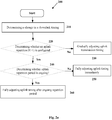
- Fig. 2a illustrates a method 200, performed by a wireless communication device 110, for uplink transmission timing control adjustment according to an exemplary embodiment, where the wireless communication device 110 is served by the network node 120 and configured to operate in a coverage enhancement mode comprising a repetitive transmission of an uplink signal within a repetition period.
- the wireless communication device 110 is served by the network node 120 and may be configured to operate in a coverage enhancement mode, where the coverage enhancement mode comprises a repetitive transmission of an uplink signal during a repetition period.
- the first determining unit 310 may be configured to determine a change in a downlink timing of the network node 120
- the adjusting unit 330 may be configured to, in response to the change in the downlink timing and the repetition period being ongoing, perform an adjustment of an uplink transmission timing outside the ongoing repetition period.
- wireless communication device 110 More details regarding the wireless communication device 110 may be described in connection with Figs. 2a and 3a hereinafter.
- the first determining unit 310 may be configured to determine that the downlink timing of the serving cell or the network node 120 has changed, at step 210, and the third determining unit 340 may be configured to check or determine whether uplink repetitions of repetition factor R larger than 1 are configured by the network node 120, at step 220. If no such repetitions are configured, the uplink transmission timing may be gradually adjusted according to the legacy rules on gradual adjustment, such as rules specified in 3GPP TS 36.133 V12.7.0, Section 7.1.2, at step 230.
- the rules may comprise one or more of the conditions consisting of: a. the maximum amount of the magnitude of the timing change in one adjustment shall be Tq seconds, b. the minimum aggregate adjustment rate shall be 7 ⁇ Ts per second, and c. the maximum aggregate adjustment rate shall be Tq per 200ms, d.
- Tq is depending on downlink and uplink characteristics and is mapped on the downlink bandwidth, e.g., as in Table 1 below.
- the downlink characteristics comprise any or a combination of: downlink system bandwidth, and coverage enhancement mode of operation, e.g., Mode A or Mode B operation, or an operation of repetitions.
- the uplink characteristics may comprise any or a combination of: uplink system bandwidth, subcarrier distance or spacing, symbol length and cyclic prefix length.
- the second determining unit 330 may be configured to check whether it is currently engaged in an uplink transmission where messages are repeated, at step 240. If not, the adjusting unit 320 may be configured to fully adjust the uplink transmission timing substantially immediately in response to the changed downlink timing in the cell or the network node 120, at step 250.
- the uplink transmission timing may be adjusted to within ⁇ Te seconds before the uplink repetition period begins, and shall remain constant during the next uplink repetition period, where Te is depending on the above downlink and uplink characteristics, and the uplink transmission timing shall remain constant during the uplink repetition period.
- the adjusting unit 320 may be configured to postpone the uplink transmission timing adjustment until the current uplink transmission period has ended, and preferably substantially immediately thereafter, to be prepared for the next uplink transmission as early as possible, at step 260.
- the uplink transmission timing may be adjusted to within ⁇ Te seconds before the next uplink repetition period or next uplink transmission begins and after the ongoing uplink transmission period has ended, and shall remain constant during the next ongoing uplink repetition period, where Te is depending on the above downlink and uplink characteristics.
- the first determining unit 310 may be further configured to determine a change in a downlink timing of a reference signal received at the wireless communication device from the network node with respect to a reference time. For example, the first determining unit 310 may be further configured to determine a relative change of timing of one or more reference signals broadcasted by the network node on the downlink, to a timing predicted for the reference signals by the wireless communication device based on one or more previous reference signals.
- the third determining unit 340 may be further configured to check whether a repetition period is longer than one radio resource time unit, based on DCI transmitted by the network node, where the DCI contains explicit or implicit information on the number of repetitions to use for a granted uplink transmission, e.g., applicable for PUSCH, depending on DCI and maxRepetitions. Besides, this checking step may be based on RRC configuration provided by the network node, where the RRC configuration contains the number of resources for the wireless communication device in a radio resource time unit, and where said number of resources explicitly or implicitly indicates the number of repetitions, e.g., applicable for PUCCH, depending on #RBs and maxRepetitions.
- One radio resource time unit may correspond to one EUTRAN subframe (1ms), e.g., applicable for eMTC, or to two EUTRAN subframes (2ms), e.g., applicable for NB-IoT3.75 kHz option.
- the presently disclosed techniques include methods implemented in a wireless communication device 110, such as UE, which is served by the network node and is configured to transmit one uplink signal with repetition during a repetition period. These methods may include, for example, the steps of: determining, by the first determining unit 310, a change in a downlink timing of the network node, 210; and in response to the change in the downlink timing and the ongoing repetition period, performing, by the adjusting unit 320, an adjustment of an uplink transmission timing outside the ongoing repetition period, 260.
- the method may further comprise the steps of: determining whether the UE is configured to transmit a first uplink signal with a certain repetition over a time period, TO; determining an adjustment time resource in which the uplink transmit timing for transmitting the first signal is adjusted, which adjustment time resource is determined in response to the determined change in the downlink reception timing and depends on whether the UE is configured with the first signal with or without repetitions (e.g., adjustment time resource such as a subframe occurs immediately after T0 if repetition is configured).
- a UE that is configured to transmit any of various uplink signals (e.g., PRACH, SRS, PUSCH, M-PUCCH, NB-PUSCH, NB-PUCCH, etc) on the uplink using a repetition factor R that is larger than one, i.e., R>1, shall consider the onset of each separate repetition period to be an initial transmission. Moreover, in the cases of FDD or TDD mode of operation, the UE shall not, when R>1, carry out autonomous changes of the uplink timing during the current repetition burst, i.e., uplink transmission period or duration over which an uplink signal being transmitted is repeated.
- R repetition factor
- This new UE behavior is needed because when message repetition is used it is undesirable to have the UE changing the uplink transmit timing during the repetition period. Any change in the UE uplink timing may destroy the channel estimation at the base station receiver. This in turn will prevent the base station receiver from receiving or correctly receiving signals transmitted by the UE with repetition.
- the UE is configured to transmit one signal with repetition over the entire repetition period (TO).
- the UE can be configured to transmit only PUSCH with 32 repetitions over 32 consecutive uplink time resources, e.g., 32 subframes, 32 TTIs, 32 interleaving time periods, etc. This corresponds to a repetition period (T0) of 32 ms for FDD.
- T0 in case of HD-FDD and TDD will be longer than 32 milliseconds (ms); the actual value of T0 would depend on the number of uplink subframes available in a frame.
- the presently disclosed techniques include methods implemented in a wireless communication device, such as UE, for adjusting uplink timing when configured to transmit combination of signals with and without repetitions during a repetition period.
- the UE is configured to operate in a coverage enhancement mode comprising a repetitive transmission of a first uplink signal during a first repetition period and a transmission of a second uplink signal without a repetition.
- These methods include determining, e.g., by the first determining unit 310, a change in a downlink timing of the serving network node or cell, at step 210, and in response to the change in the downlink timing and the ongoing repetition period, performing, e.g., by the adjusting unit 320, an adjustment of an uplink transmission timing of the first uplink signal outside the first repetition period, at step 260.
- the step of performing may further configure the second uplink signal with the same uplink transmission timing as that of the first uplink signal.
- the UE is configured to transmit at least one first signal with repetition over a repetition period (TO) and also another second signal during the repetition period of the first signal, i.e., during T0.
- the UE can be configured to transmit PUSCH with 32 repetitions over T0 and the UE may also perform at least one random access transmission during T0.
- the UE performs RA during T0 with one transmission attempt, i.e., an original transmission only, without repetitions.
- the UE may initiate a RA transmission autonomously or in response to a request received from the network node.
- the UE may perform a RA transmission for one or more of the following reasons, e.g., for performing or enabling eNB to perform positioning measurement such as TA, UE Rx-Tx time difference, eNB Rx-Tx time difference, etc.
- a RA transmission can, in principle, occur at any time uncorrelated with the first signal.
- the UE is not allowed to perform any autonomous uplink timing corrections even when transmitting the second signal during an ongoing uplink repetition period, T0 of the first signal.
- the UE may adjust its timing autonomously at the start or at the end of the current repetition period of the first signal. More specifically, the UE may transmit the RA during T0 using the same timing which is being used for transmitting PUSCH. This timing was the most favorable at the start of T0.
- T0 repetition period
- T0 in case of HD-FDD and TDD will be longer than 32 ms; the actual value of T0 would depend on the number of uplink subframes available in a frame.
- the presently disclosed techniques include methods implemented in a wireless communication device 100, such as a UE, of adjusting uplink timing when the wireless communication device 100 is configured to transmit multiple signals with repetitions during overlapping repetition periods.
- the UE may be configured to operate in a coverage enhancement mode comprising repetitive transmissions of at least two uplink signals with at least partly overlapping repetition periods comprising a first uplink signal with a certain repetition over a time period T1 and a second uplink signal with a certain repetition over a time period T2.
- These methods may comprise: determining, by the first determining unit 310, a change in a downlink timing of the serving network node or cell, at step 210, and in response to the change in the downlink timing and the ongoing repetition period(s), performing, by the adjusting unit 320, uplink transmission timings outside both of the first and second repetition periods, at step 260.
- the methods may further comprise a step of determining an adjustment time resource in which the uplink transmit timing for transmitting at least one of the first signal and the second signal is adjusted, which adjustment time resource is determined in response to the determined change in the downlink reception timing and further depends on the relations between the starting times of T1 and T2 and/or terminating times of T1 and T2 (e.g., an adjustment time resource such as a subframe occurs immediately after T2, if T2 terminates after T1).
- the UE is configured to transmit at least one first signal with a certain repetition over a first repetition period T1 and at least a second signal with a certain repetition over a second repetition period T2. It is further assumed that T1 and T2 at least partly overlap.
- the UE can be configured to transmit a first signal, such as PUSCH, with 32 repetitions over T1.
- the UE may also be configured to transmit a second signal, such as a random access, with a certain number of repetitions during T2.
- a UE may initiate RA transmission autonomously or in response to a request received from the network node.
- the UE may perform RA transmission for one or more of the following reasons, e.g., for performing or enabling eNB to perform positioning measurement such as TA, UE Rx-Tx time difference, eNB Rx-Tx time difference, etc.
- the UE behavior can be further described as follows.
- the UE is not allowed to perform any autonomous uplink transmit timing corrections or adjustments during ongoing uplink repetition periods of any of the uplink signals but is allowed to autonomously adjust its uplink transmit timing when no repetition period is ongoing, such as: before the beginning of the repetition period of a signal with the earliest starting time compared to the starting times of repetition periods of other signals overlapping in time, or after the end of the repetition period of a signal with the latest terminating time compared to the terminating times of repetition periods of other signals overlapping in time.
- the above UE behavior is elaborated with the example comprising the first and second signal transmission with at least partly overlapping repetition periods of T1 and T2 respectively. Assume that T1 starts before T2 and T1 ends before T2, i.e., T2 terminates after T1.
- the UE is not allowed to autonomously adjust its uplink timing from the start of T1 and until the end of T2. However, the UE is allowed to autonomously adjust or change its uplink transmit timing just before T1 or just after T2.
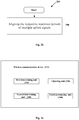
- Fig. 2b illustrates a method 280 performed by a wireless communication device 110 for uplink transmission timing control, according to other exemplary embodiments of the presently disclosed techniques.
- the method 280 may be implemented in a UE (e.g., involving a RA transmission, etc.).
- the wireless communication device 110 is served by a network node 120 and configured to operate in a coverage enhancement mode, wherein the coverage enhancement mode comprises repetitive transmissions of multiple uplink signals with respective repetition periods.
- the method 280 may comprise aligning the respective repetition periods by shifting in time at least one of start or end points of the respective repetition periods according to a predetermined rule, such that an overlap time of the respective repetition periods is maximized or single transmission of the multiple uplink signals is minimized, at step 290.
- the predetermined rule comprises one of:
- the UE is configured by the network node to transmit the first signal, PUSCH, with a certain repetition over the repetition period of T1.
- the network node may further request the UE to transmit a second signal, such as a random access, with a certain repetition over the repetition period of T2.
- the UE may be configured to transmit RA with all repetitions by the end of T1, i.e., T2 ends in the single and last time resource just before or after the T1.
- T2 the UE is allowed to adjust its uplink transmit timing immediately after T1, or one time resource after T1.
- the UE transmit timing adjustment is not delayed or the adjustment is applied with minimal delay when there are two or more signals configured for uplink transmissions with overlapping repetition periods.
- the transmission during T1 has precedence over the transmission in T2, and since T2 extends over the remaining time of T1, the UE can correct the timing at the start of T1.
- the UE would not be allowed to correct the timing at the onset of T2, since there would be a part of T1 left after T2 had been started.
- the aim of this approach is to allow alignment between the repetition periods of multiple uplink signals as much as possible.
- This alignment enables the UE to adjust the uplink transmit timing immediately or with a shorter delay after the end of the repetition period of each uplink signal.
- the overlap time of the repetition periods (Ta, Tb) is maximized, or single transmission of uplink signals is minimized.
- Fig. 3b is a simplified block diagram of a wireless communication device 110 that may be configured to carry out one or more of the techniques described herein.
- the wireless communication device 110 may comprise, but is not limited to, an Input/Output Interface 370, processor(s) 360, and a memory 350, operatively coupled with each other.
- the memory 350 may comprise, but not be limited to, a volatile (e.g., RAM) and/or non-volatile memory (e.g., a hard disk or flash memory).
- the memory 350 may be configured to store a computer program, which when executed by the processor(s) 360, causes to the processor 360 to perform any method performed in the wireless communication device 110.
- the combination of processor(s) 360 with such a memory 350 may be referred to as a processing circuit; it will be appreciated that when the memory 350 stores a computer program for carrying out one or more of the techniques described herein, the processing circuit is thereby configured to carry out those one or more techniques.
- the computer program can be stored in a remote location, for example computer program product 380, and be accessible by the processor(s) 360 via, for example carrier 390.
- the computer program product 380 can be distributed and/or stored on a removable computer readable media, e.g., diskette, CD (Compact Disk), DVD (Digital Video Disk), flash or similar removable memory media (e.g., compact flash, SD secure digital, memory stick, miniSD, MMC multimedia card, smart media), HD-DVD (High Definition DVD), or Bluray DVD, USB (Universal Serial Bus) based removable memory media, magnetic tape media, optical storage media, magneto-optical media, bubble memory, or distributed as a propagated signal via a network (e.g., Ethernet, ATM, ISDN, PSTN, X.25, Internet, Local Area Network (LAN), or similar networks capable of transporting data packets to the infrastructure node).
- a network e.g., Ethernet, ATM, ISDN, PSTN, X.25, Internet, Local Area Network (LAN), or similar networks capable of transporting data packets to the infrastructure node.
- Fig. 4 illustrates an example method 400 performed on the network side of the wireless communication system, such as in a network node 120, a cloud, or the like, for uplink transmission timing control, according to an exemplary embodiment.
- the network node 120 may be configured to enhance an uplink transmission timing adjustment procedure for a wireless communication device 110 served by the network node 120.
- the network node 120 may comprise, but not limited to, a determining unit 510, an enabling unit 520 and a transmitting unit 530.
- the determining unit 510 may be configured to determine that the wireless communication device 110 is to be configured to transmit at least two uplink signals over at least partly overlapping repetition periods.
- the enabling unit 520 may be configured to enable the wireless communication device 110 to align the respective repetition periods of the at least two uplink signals. More details regarding the network node 120 may be described in connection with Figs. 4, 5a and 5b hereinafter.
- a method 400 for enhancing an uplink transmission timing adjustment procedure for a wireless communication device 110 may comprise the steps of: determining, by the determining unit 510, that the wireless communication device 100 is to be configured to transmit at least two uplink signals over at least partly overlapping repetition periods, e.g., as shown at step 410 of Figure 4 ; and enabling, by the enabling unit 520, the wireless communication device 110 to align the respective repetition periods of the at least two uplink signals, as shown at step 420 of Figure 4 .
- the enabling unit 520 may be further configured to enable the wireless communication device 110 to align the respective repetition periods by shifting in time at least one of the start or end points of the respective repetition periods according to a predetermined rule, such that an overlap time of the respective repetition periods is maximized or single transmission of the multiple uplink signals is minimized.
- the predetermined rule comprises one of:
- the UE is configured by the network node to transmit the first signal, PUSCH, with a certain repetition over the repetition period of T1.
- the network node may further request the UE to transmit a second signal, random access, with a certain repetition over the repetition period of T2.
- the UE may be configured to transmit RA with all repetitions by the end of T1, i.e., T2 ends in the single and last time resource just before or after the T1.
- T2 By scheduling T2 at the end of T1, the UE is allowed to adjust its uplink transmit timing immediately after T1, or one time resource after T1.
- the UE transmit timing adjustment is not delayed or the adjustment is applied with minimal delay when there are two or more signals configured for uplink transmissions with overlapping repetition periods.
- the transmission during T1 has precedence over the transmission in T2, and since T2 extends over the remaining time of T1, the UE can correct the timing at the start of T1.
- the UE would not be allowed to correct the timing at the onset of T2, since there would be a part of T1 left after T2 had been started.
- the aim of this approach is to allow alignment between the repetition periods of multiple uplink signals as much as possible.
- This alignment enables the UE to adjust the uplink transmit timing immediately or with a shorter delay after the end of the repetition period of each uplink signal.
- the overlap time of the repetition periods (Ta, Tb) is maximized or single transmission of uplink signals is minimized.
- Fig. 5b is a simplified block diagram of an example network node 120, which may be configured to carry out one or more of the techniques described herein.
- the network node 120 may comprise, but is limited to, an Input/Output Interface 570, processor(s) 560, and a memory 550, operatively coupled with each other.
- the memory 550 may comprise, but not be limited to, a volatile (e.g., RAM) and/or non-volatile memory (e.g., a hard disk or flash memory).
- the memory 550 may be configured to store a computer program, which when executed by the processor(s) 560, causes the processor(s) 560 to perform any method performed in the network node 120.
- the combination of processor(s) 560 with such a memory 550 may be referred to as a processing circuit; it will be appreciated that when the memory 550 stores a computer program for carrying out one or more of the techniques described herein, the processing circuit is thereby configured to carry out those one or more techniques.
- the computer program can be stored in a remote location, for example computer program product 580, and be accessible by the processor 560 via, for example carrier 590.
- the computer program product 580 can be distributed and/or stored on a removable computer readable media, e.g., diskette, CD (Compact Disk), DVD (Digital Video Disk), flash or similar removable memory media (e.g., compact flash, SD secure digital, memory stick, miniSD, MMC multimedia card, smart media), HD-DVD (High Definition DVD), or Bluray DVD, USB (Universal Serial Bus) based removable memory media, magnetic tape media, optical storage media, magneto-optical media, bubble memory, or distributed as a propagated signal via a network (e.g., Ethernet, ATM, ISDN, PSTN, X.25, Internet, Local Area Network (LAN), or similar networks capable of transporting data packets to the infrastructure node).
- a network e.g., Ethernet, ATM, ISDN, PSTN, X.25, Internet, Local Area Network (LAN), or similar networks capable of transporting data packets to the infrastructure node.
- Examples of the first node are NodeB, MeNB, SeNB, a network node belonging to MCG or SCG, base station (BS), multi-standard radio (MSR) radio node such as MSR BS, eNodeB, network controller, radio network controller (RNC), base station controller (BSC), relay, donor node controlling relay, base transceiver station (BTS), access point (AP), transmission points, transmission nodes, RRU, RRH, nodes in distributed antenna system (DAS), core network node (e.g., MSC, MME etc), O&M, OSS, SON, positioning node (e.g., E-SMLC), MDT, etc.
- BS base station
- MSR multi-standard radio
- RNC radio network controller
- BSC base station controller
- relay donor node controlling relay
- BTS base transceiver station
- AP access point
- DAS distributed antenna system
- core network node e.g., MSC, MME etc
- O&M core network no
- Examples of the second node are target device, device to device (D2D) UE, proximity capable UE (also referred to asProSe UE), machine-type UE or UE capable of machine to machine (M2M) communication, PDA, PAD, Tablet, mobile terminals, smart phone, laptop embedded equipped (LEE), laptop mounted equipment (LME), USB dongles, etc.
- D2D device to device
- ProSe UE proximity capable UE
- M2M machine-type UE or UE capable of machine to machine (M2M) communication
- PDA personal area network
- PAD tablet
- mobile terminals smart phone
- LEE laptop embedded equipped
- LME laptop mounted equipment
- USB dongles etc.
- ProSe also known as D2D, sidelink
- the ProSe operation by a UE is in a half-duplex mode, i.e., the UE can either transmit ProSe signals/channels or receive ProSe signals/channels.
- the ProSe UEs can also act as ProSe relay UEs whose tasks are to relay some signals between ProSe UEs, but also to other nodes (e.g., network node).
- There is also associated control information for ProSe some of which is transmitted by ProSe UEs and the other is transmitted by eNBs (e.g., ProSe resource grants for ProSe communication transmitted via cellular downlink control channels).
- the ProSe transmissions may occur on resources which are configured by the network or selected autonomously by the ProSe UE.
- the ProSe transmissions (e.g., PSDCH) include several (e.g., 3) retransmissions that are transmitted on consecutive subframes. The retransmissions or repetitions are needed to achieve good SD-RSRP measurement performance.
- the SD-RSRP measurement is used to perform ProSe relay selection by ProSe UEs.
Landscapes
- Engineering & Computer Science (AREA)
- Computer Networks & Wireless Communication (AREA)
- Signal Processing (AREA)
- Mobile Radio Communication Systems (AREA)
Claims (30)
- Système de communication sans fil (100) comprenant:un dispositif de communication sans fil (110) configuré pour prendre en charge un mode d'amélioration de couverture comprenant une transmission répétitive d'un premier signal de liaison montante pendant une première période de répétition; etun nœud de réseau (120) desservant le dispositif de communication sans fil (110), le nœud de réseau comprenant un émetteur (530) configuré pour transmettre un signal de référence au dispositif de communication sans fil (110),caractérisé en ce que le dispositif de communication sans fil (110) comprend un circuit de traitement (360) configuré pour:déterminer un changement d'une synchronisation de liaison descendante sur la base du signal de référence (310);déterminer si la première période de répétition est en cours (330); et,en réponse au changement de la synchronisation de liaison descendante et la première période de répétition étant en cours, effectuer un ajustement d'une synchronisation de transmission de liaison montante en dehors de la première période de répétition (320).
- Système de communication sans fil selon la revendication 1, dans lequel le nœud de réseau (120) comprend un circuit de traitement (560) configuré pour:déterminer que le dispositif de communication sans fil (110) doit être configuré pour transmettre un deuxième signal de liaison montante pendant une deuxième période de répétition chevauchant au moins partiellement la première période de répétition (510); etpermettre au dispositif de communication sans fil (110) d'aligner la première période de répétition et la deuxième période de répétition selon une règle prédéterminée, de telle sorte qu'un temps de chevauchement de la première période de répétition et de la deuxième période de répétition soit maximisé ou qu'une transmission unique des signaux de liaison montante multiple soit minimisée (520).
- Système de communication sans fil selon la revendication 2, dans lequel la règle prédéterminée comprend l'une parmi:la première période de répétition et la deuxième période de répétition commencent en même temps;la première période de répétition et la deuxième période de répétition se terminent en même temps;la première période de répétition et la deuxième période de répétition commencent durant une première durée; etla première période de répétition et la deuxième période de répétition se terminent durant une deuxième durée.
- Système de communication sans fil selon l'une quelconque des revendications 1 à 3, dans lequel le circuit de traitement (360) du dispositif de communication sans fil (110) est configuré pour déterminer si la première période de répétition est plus longue qu'une unité de temps de ressource radio (340), sur la base de l'une parmi :une information de commande de liaison descendante, DCI, transmise par le nœud de réseau (120), dans lequel la DCI contient des informations explicites ou implicites sur un certain nombre de répétitions à utiliser pour la transmission répétitive des premiers signaux de liaison montante etune configuration de commande de ressources radio, RRC, fournie par le nœud de réseau (120), dans lequel la configuration de RRC contient un certain nombre de ressources pour le dispositif de communication sans fil (110) dans une unité de temps de ressource radio, et dans lequel le nombre de ressources indique explicitement ou implicitement le nombre de répétitions.
- Procédé (200) pour un ajustement de synchronisation de transmission de liaison montante dans un dispositif de communication sans fil (110) desservi par un nœud de réseau (120) et configuré pour prendre en charge un mode d'amélioration de couverture, dans lequel le mode d'amélioration de couverture comprend une transmission répétitive d'un premier signal de liaison montante pendant une première période de répétition, caractérisé en ce qu'il comprend:la détermination d'un changement dans une synchronisation de liaison descendante (210);la détermination selon laquelle la première période de répétition est en cours (240); eten réponse au changement de la synchronisation de liaison descendante et de la première période de répétition en cours, l'exécution d'un ajustement d'une synchronisation de transmission de liaison montante en dehors de la première période de répétition (260).
- Procédé selon la revendication 5, dans lequel la détermination d'un changement d'une synchronisation de liaison descendante (210) comprend:
la détermination d'un changement d'une synchronisation de liaison descendante d'un signal de référence reçu au niveau du dispositif de communication sans fil (110) du nœud de réseau (120) par rapport à un temps de référence. - Procédé selon la revendication 6, dans lequel la détermination d'un changement d'une synchronisation de liaison descendante (210) comprend:
la détermination d'un changement relatif de synchronisation d'un ou plusieurs signaux de référence diffusés par le nœud de réseau (120) sur la liaison descendante, à une synchronisation prédite pour les signaux de référence par le dispositif de communication sans fil (110) sur la base d'un ou plusieurs signaux de référence précédents. - Procédé selon l'une quelconque des revendications 5 à 7, dans lequel la synchronisation de transmission de liaison montante est ajustée à ± Te secondes avant le début d'une transmission de liaison montante suivante et après la fin de la période de transmission de liaison montante, et dans lequel Te indique une valeur de limite d'erreur de synchronisation et dépend des caractéristiques de liaison descendante et de liaison montante.
- Procédé selon l'une quelconque des revendications 5 à 7, dans lequel le mode d'amélioration de couverture comprend en outre une transmission d'un deuxième signal de liaison montante sans répétition, et dans lequel l'étape d'exécution (260) comprend en outre:
la configuration du deuxième signal de liaison montante avec une même synchronisation de transmission de liaison montante que celle du premier signal de liaison montante. - Procédé selon l'une quelconque des revendications 5 à 7, dans lequel le mode d'amélioration de couverture comprend en outre une transmission répétitive d'un deuxième signal de liaison montante avec une deuxième période de répétition chevauchant au moins partiellement la première période de répétition, et dans lequel l'étape d'exécution (260) comprend en outre:
en réponse au changement de la synchronisation de liaison descendante, effectuer l'ajustement de la synchronisation de transmission de liaison montante en dehors des première et deuxième périodes de répétition. - Procédé selon l'une quelconque des revendications 5 à 7, dans lequel si la première période de répétition n'est pas en cours, la synchronisation de transmission de liaison montante est ajustée à ± Te secondes avant le début de la première période de répétition, et dans lequel Te est indicatif d'une valeur de limite d'erreur de synchronisation et dépend des caractéristiques de liaison descendante et de liaison montante.
- Procédé selon l'une quelconque des revendications 8 et 11, dans lequel les caractéristiques de liaison montante comprennent l'une ou une combinaison de la largeur de bande de système de liaison montante, la distance de sous-porteuse, la longueur de symbole, la longueur de préfixe cyclique, et dans lequel les caractéristiques de liaison descendante comprennent l'un ou une combinaison de la largeur de bande de système de liaison descendante, et un mode de fonctionnement de répétition.
- Procédé selon l'une quelconque des revendications 5 à 7, comprenant en outre la détermination si la première période de répétition est plus longue qu'une unité de temps de ressource radio, sur la base de l'une parmi (220):une information de commande de liaison descendante, DCI, transmise par le nœud de réseau, dans lequel la DCI contient des informations explicites ou implicites sur un certain nombre de répétitions à utiliser pour la transmission répétitive des premiers signaux de liaison montante, etune configuration de commande de ressources radio, RRC, fournie par le nœud de réseau, dans lequel la configuration de RRC contient un certain nombre de ressources pour le dispositif de communication sans fil dans une unité de temps de ressource radio, et dans lequel le nombre de ressources indique explicitement ou implicitement le nombre de répétitions.
- Procédé selon la revendication 13, dans lequel si la première période de répétition n'est pas plus longue qu'une unité de temps de ressource radio, la synchronisation de transmission de liaison montante est ajustée selon une règle comprenant les conditions suivantes:a. une amplitude maximale d'un changement de synchronisation d'un ajustement doit être Tq secondes;b. un taux d'ajustement global minimal doit être de 7 * Ts par seconde, dans lequel Ts est une unité de synchronisation de base; etc. le taux d'ajustement global maximal doit être Tq par 200 ms, dans lequel Tq dépend des caractéristiques de liaison descendante et de liaison montante.
- Procédé selon la revendication 14, dans lequel Tq est mappé sur une largeur de bande de liaison descendante selon un tableau suivant :
Bande passante de liaison descendante (MHZ) Tq 1,4 17,5 Ts 3 9, 5 Ts 5 5,5 Ts ≥ 10 3,5 Ts - Procédé selon l'une quelconque des revendications 13 à 15, dans lequel l'unité de temps d'une ressource radio correspond à une sous-trame d'un réseau d'accès radio terrestre universel évolué, EUTRAN, ou deux sous-trames EUTRAN.
- Procédé selon l'une quelconque des revendications 5 à 16, dans lequel le dispositif de communication sans fil comprend au moins l'un parmi:un dispositif de communication de type machine évoluée, eMTC; etun dispositif Internet des objets à bande étroite, NB-IoT.
- Dispositif de communication sans fil (110) desservi par un nœud de réseau (120) et configuré pour prendre en charge un mode d'amélioration de couverture, dans lequel le mode d'amélioration de couverture comprend une transmission répétitive d'un premier signal de liaison montante pendant une première période de répétition, caractérisé en ce que le dispositif de communication sans fil (110) comprend un circuit de traitement (360) configuré pour:déterminer un changement dans une synchronisation de liaison descendante (310);déterminer si la première période de répétition est en cours (330); et,en réponse au changement de la synchronisation de liaison descendante et de la première période de répétition en cours, effectuer un ajustement d'une synchronisation de transmission de liaison montante en dehors de la première période de répétition (320).
- Dispositif de communication sans fil selon la revendication 18, dans lequel le circuit de traitement (360) est en outre configuré pour:
déterminer un changement dans une synchronisation de liaison descendante d'un signal de référence reçu au dispositif de communication sans fil (110) à partir du nœud de réseau (120) par rapport à un temps de référence. - Dispositif de communication sans fil selon la revendication 19, dans lequel le circuit de traitement (360) est en outre configuré pour:
déterminer un changement relatif de synchronisation d'un ou plusieurs signaux de référence diffusés par le nœud de réseau (120) sur la liaison descendante, à une synchronisation prédite pour les signaux de référence par le dispositif de communication sans fil (110) sur la base d'un ou plusieurs signaux de référence précédents. - Dispositif de communication sans fil selon l'une quelconque des revendications 18 à 20, dans lequel la synchronisation de transmission de liaison montante est ajustée à ± Te secondes avant le début d'une transmission de liaison montante suivante et après la fin de la période de transmission de liaison montante en cours, et dans lequel Te indique une valeur de limite d'erreur de synchronisation et dépend des caractéristiques de liaison descendante et de liaison montante.
- Dispositif de communication sans fil selon l'une quelconque des revendications 18 à 20, dans lequel le mode d'amélioration de couverture comprend en outre une transmission d'un deuxième signal de liaison montante sans répétition, et dans lequel le circuit de traitement (360) est en outre configuré pour:
configurer le deuxième signal de liaison montante avec une même synchronisation de transmission de liaison montante que celle du premier signal de liaison montante. - Dispositif de communication sans fil selon l'une quelconque des revendications 18 à 20, dans lequel le mode d'amélioration de couverture comprend en outre une transmission répétitive d'un deuxième signal de liaison montante avec une deuxième période de répétition chevauchant au moins partiellement la première période de répétition, et dans lequel le circuit de traitement (360) est en outre configuré pour:
en réponse au changement de la synchronisation de liaison descendante, effectuer l'ajustement de la synchronisation de transmission de liaison montante en dehors des première et deuxième périodes de répétition. - Dispositif de communication sans fil selon l'une quelconque des revendications 18 à 20, dans lequel le circuit de traitement (360) est en outre configuré pour:
si la première période de répétition n'est pas en cours, régler la synchronisation de transmission de liaison montante à ± Te secondes avant le commencement de la première période de répétition, dans lequel Te indique une valeur de limite d'erreur de synchronisation et dépend des caractéristiques de liaison descendante et de liaison montante. - Dispositif de communication sans fil selon l'une quelconque des revendications 21 et 24, dans lequel les caractéristiques de liaison montante comprennent l'un ou une combinaison de la bande passante de système de liaison montante, l'espacement de sous-porteuse, la longueur de symbole, la longueur de préfixe cyclique, et dans lequel les caractéristiques de liaison descendante comprennent l'un ou une combinaison de la bande passante de système de liaison descendante et un mode de fonctionnement de répétition.
- Dispositif de communication sans fil selon l'une quelconque des revendications 18 à 20, dans lequel le circuit de traitement (360) est en outre configuré pour déterminer si la première période de répétition est plus longue qu'une unité de temps de ressource radio (340), sur la base de l'une parmi :une information de commande de liaison descendante, DCI, transmise par le nœud de réseau, dans lequel la DCI contient des informations explicites ou implicites sur un certain nombre de répétitions à utiliser pour la transmission répétitive des premiers signaux de liaison montante, etune configuration de commande de ressources radio, RRC, fournie par le nœud de réseau, dans lequel la configuration de RRC contient un certain nombre de ressources pour le dispositif de communication sans fil dans une unité de temps de ressource radio, et dans lequel le nombre de ressources indique explicitement ou implicitement le nombre de répétitions.
- Dispositif de communication sans fil selon la revendication 26, dans lequel le circuit de traitement (360) est en outre configuré pour, si la première période de répétition n'est pas plus longue qu'une unité de temps de ressource radio, ajuster le temps de transmission de liaison montante selon une règle comprenant les conditions suivantes :a. une amplitude maximale d'un changement de synchronisation d'un ajustement doit être Tq secondes ;b. un taux d'ajustement global minimal doit être de 7 * Ts par seconde, dans lequel Ts est une unité de synchronisation de base ; etc. le taux d'ajustement global maximal doit être Tq par 200 ms, dans lequel Tq dépend des caractéristiques de liaison descendante et de liaison montante.
- Dispositif de communication sans fil selon la revendication 27, dans lequel Tq est mappé sur une largeur de bande de liaison descendante selon un tableau suivant :
Bande passante de liaison descendante (MHZ) Tq 1,4 17,5 Ts 3 9, 5 Ts 5 5,5 Ts ≥ 10 3,5 Ts - Dispositif de communication sans fil selon les revendications 26 à 28, dans lequel l'unité de temps de ressource radio correspond à une sous-trame d'un réseau d'accès radio terrestre universel évolué, EUTRAN, ou deux sous-trames EUTRAN.
- Dispositif de communication sans fil selon l'une quelconque des revendications 18 à 29, dans lequel le dispositif de communication sans fil comprend au moins l'un parmi:un dispositif de communication de type machine évoluée, eMTC; etun dispositif Internet des objets à bande étroite, NB-IoT.
Priority Applications (1)
| Application Number | Priority Date | Filing Date | Title |
|---|---|---|---|
| EP20195617.4A EP3826383B1 (fr) | 2016-03-31 | 2017-03-28 | Commande de synchronisation de transmission de liaison montante |
Applications Claiming Priority (3)
| Application Number | Priority Date | Filing Date | Title |
|---|---|---|---|
| CNPCT/CN2016/078095 | 2016-03-31 | ||
| US15/253,318 US10555297B2 (en) | 2016-03-31 | 2016-08-31 | Uplink transmission timing control |
| PCT/EP2017/057268 WO2017167723A2 (fr) | 2016-03-31 | 2017-03-28 | Commande de synchronisation de transmission en liaison montante |
Related Child Applications (1)
| Application Number | Title | Priority Date | Filing Date |
|---|---|---|---|
| EP20195617.4A Division EP3826383B1 (fr) | 2016-03-31 | 2017-03-28 | Commande de synchronisation de transmission de liaison montante |
Publications (2)
| Publication Number | Publication Date |
|---|---|
| EP3437388A2 EP3437388A2 (fr) | 2019-02-06 |
| EP3437388B1 true EP3437388B1 (fr) | 2020-09-16 |
Family
ID=59959960
Family Applications (2)
| Application Number | Title | Priority Date | Filing Date |
|---|---|---|---|
| EP20195617.4A Active EP3826383B1 (fr) | 2016-03-31 | 2017-03-28 | Commande de synchronisation de transmission de liaison montante |
| EP17714185.0A Active EP3437388B1 (fr) | 2016-03-31 | 2017-03-28 | Commande de synchronisation de transmission en liaison montante |
Family Applications Before (1)
| Application Number | Title | Priority Date | Filing Date |
|---|---|---|---|
| EP20195617.4A Active EP3826383B1 (fr) | 2016-03-31 | 2017-03-28 | Commande de synchronisation de transmission de liaison montante |
Country Status (9)
| Country | Link |
|---|---|
| US (2) | US10555297B2 (fr) |
| EP (2) | EP3826383B1 (fr) |
| JP (2) | JP6653394B2 (fr) |
| KR (2) | KR102126403B1 (fr) |
| CN (2) | CN108886756B (fr) |
| ES (1) | ES2832623T3 (fr) |
| HU (1) | HUE053201T2 (fr) |
| WO (1) | WO2017167723A2 (fr) |
| ZA (1) | ZA201805930B (fr) |
Families Citing this family (31)
| Publication number | Priority date | Publication date | Assignee | Title |
|---|---|---|---|---|
| US10541802B2 (en) * | 2016-03-31 | 2020-01-21 | Telefonaktiebolaget Lm Ericsson (Publ) | Application of timing advance command in wireless communication device in enhanced coverage mode |
| US10555297B2 (en) | 2016-03-31 | 2020-02-04 | Telefonaktiebolaget Lm Ericsson (Publ) | Uplink transmission timing control |
| WO2017179922A2 (fr) * | 2016-04-14 | 2017-10-19 | 엘지전자 주식회사 | Procédé de transmission d'informations en retour dans un environnement fed2d et appareil associé |
| US10645658B2 (en) * | 2016-09-06 | 2020-05-05 | Mediatek Inc. | Method and apparatus for uplink power consumption reduction in NB-IoT |
| ES2920144T3 (es) * | 2016-09-30 | 2022-08-01 | Ericsson Telefon Ab L M | Ajuste de temporización autónomo para un dispositivo inalámbrico |
| US20190350038A1 (en) * | 2017-01-05 | 2019-11-14 | Telefonaktiebolaget Lm Ericsson (Publ) | Methods and devices for facilitating discontinuous reception |
| WO2018144836A1 (fr) * | 2017-02-03 | 2018-08-09 | Intel IP Corporation | Améliorations d'acquisition d'informations de système pour dispositifs sans fil |
| US11228965B2 (en) * | 2017-03-24 | 2022-01-18 | Motorola Mobility Llc | Determining a time-frequency resource using a system parameter |
| US10939385B2 (en) * | 2017-03-30 | 2021-03-02 | Lg Electronics Inc. | Uplink transmission power control method and device using same |
| US11057800B2 (en) | 2017-05-04 | 2021-07-06 | Qualcomm Incorporated | Neighbor cell measurement and reselection for narrowband operation |
| KR102288629B1 (ko) | 2017-05-04 | 2021-08-11 | 삼성전자 주식회사 | 무선 통신 시스템에서 상향 제어 채널 전송 방법 및 장치 |
| US20180343132A1 (en) * | 2017-05-25 | 2018-11-29 | Qualcomm Inc. | Enhanced resource sharing for prs measurements |
| EP3718321A4 (fr) * | 2017-12-01 | 2021-07-21 | Nokia Technologies Oy | Partitionnement en blocs de répétitions |
| CN111343579B (zh) * | 2018-12-19 | 2021-08-06 | 大唐移动通信设备有限公司 | 一种定位方法和相关设备 |
| US10841772B2 (en) * | 2018-12-28 | 2020-11-17 | Wipro Limited | Method and system for controlling communication between internet-of-things (IOT) devices |
| CN113661747B (zh) * | 2019-02-15 | 2024-06-18 | 瑞典爱立信有限公司 | 涉及上行链路传输的方法、设备和计算机可读介质 |
| CN110225595B (zh) * | 2019-05-29 | 2022-05-24 | 成都中科微信息技术研究院有限公司 | 一种结合srs周期的调度基站及系统 |
| US11382098B2 (en) * | 2019-06-14 | 2022-07-05 | Qualcomm Incorporated | Sidelink timing control |
| CN111064539B (zh) * | 2019-12-23 | 2021-10-26 | 展讯半导体(南京)有限公司 | 一种上行同步方法、通信装置及存储介质 |
| US12416701B2 (en) * | 2020-05-13 | 2025-09-16 | Telefonaktiebolaget Lm Ericsson (Publ) | Methods and apparatuses to account for timing errors of a user equipment in positioning measurements |
| CN113973395B (zh) * | 2020-07-24 | 2024-01-26 | 维沃移动通信有限公司 | 随机接入方法、配置方法及相关设备 |
| CN114126050B (zh) * | 2020-08-27 | 2025-02-21 | 华为技术有限公司 | 下行传输的方法和通信装置 |
| CN114666885A (zh) * | 2020-12-23 | 2022-06-24 | 北京三星通信技术研究有限公司 | 同步方法、装置、设备及计算机可读存储介质 |
| JP7430283B2 (ja) | 2021-01-14 | 2024-02-09 | エルジー エレクトロニクス インコーポレイティド | カバレッジの改善 |
| US11516066B2 (en) * | 2021-01-15 | 2022-11-29 | Qualcomm Incorporated | Reference signal bundling for uplink channel repetition |
| US12317264B2 (en) * | 2021-02-19 | 2025-05-27 | Qualcomm Incorporated | Indicating PUCCH repetition factor using reference signal of preceding PDCCH |
| US20220360368A1 (en) * | 2021-05-04 | 2022-11-10 | Qualcomm Incorporated | Repetition across slot boundary handling |
| EP4445663A4 (fr) * | 2021-12-08 | 2025-07-30 | Nokia Technologies Oy | Améliorations sur la transmission en liaison montante |
| US20260040252A1 (en) * | 2022-08-04 | 2026-02-05 | Apple Inc. | Gradual Timing Adjustments for Air-to-Ground UE |
| AU2022480348A1 (en) * | 2022-09-27 | 2025-03-20 | Zte Corporation | Timing adjustment techniques for uplink transmission |
| WO2025174221A1 (fr) * | 2024-02-16 | 2025-08-21 | 엘지전자 주식회사 | Procédé de transmission et de réception de liaison montante pour ido ambiant, et appareil associé |
Family Cites Families (29)
| Publication number | Priority date | Publication date | Assignee | Title |
|---|---|---|---|---|
| CN100566232C (zh) * | 2005-08-08 | 2009-12-02 | 大唐移动通信设备有限公司 | 时分双工系统支持可变覆盖范围的方法 |
| CN101286791A (zh) * | 2007-04-13 | 2008-10-15 | 中兴通讯股份有限公司 | 时分同步码分多址接入系统的上行同步保持方法 |
| EP3654535A1 (fr) | 2008-02-01 | 2020-05-20 | Guangdong Oppo Mobile Telecommunications Corp., Ltd. | Système et procédé de synchronisation temporelle de liaison montante en conjonction avec une réception discontinue |
| US8842633B2 (en) | 2009-05-04 | 2014-09-23 | Blackberry Limited | Systems and methods for mobile stations to identify radio access technologies |
| WO2011087416A2 (fr) | 2010-01-15 | 2011-07-21 | Telefonaktiebolaget Lm Ericsson (Publ) | Traitement de synchronisation de liaison montante |
| US8761097B2 (en) * | 2010-05-19 | 2014-06-24 | Qualcomm Incorporated | Systems and methods for enhancing uplink coverage in interference scenerios |
| US9055595B2 (en) | 2011-02-15 | 2015-06-09 | Telefonaktiebolaget L M Ericsson (Publ) | Bandwidth-based configuration of measurement gaps |
| CN104254995B (zh) * | 2012-01-24 | 2018-05-11 | 交互数字专利控股公司 | 用于改善的上行链路覆盖的系统和方法 |
| EP3937551A3 (fr) | 2012-01-25 | 2022-02-09 | Comcast Cable Communications, LLC | Canal d'accès aléatoire dans des communications sans fil à porteuses multiples avec des groupes d'avance temporelle |
| EP2813112B1 (fr) * | 2012-02-07 | 2018-08-01 | Telefonaktiebolaget LM Ericsson (publ) | Signaux de référence dans une communication sans fil |
| US9167547B2 (en) | 2012-09-27 | 2015-10-20 | Blackberry Limited | Uplink timing maintenance upon time alignment timer expiry |
| CN105493417B (zh) * | 2013-07-26 | 2018-11-09 | Lg 电子株式会社 | 发送用于mtc的信号的方法及其设备 |
| WO2015056947A1 (fr) * | 2013-10-14 | 2015-04-23 | 엘지전자 주식회사 | Procédé de renforcement de la couverture dans un système de communications sans fil, et appareil à cet effet |
| CN104581925B (zh) | 2013-10-29 | 2019-01-08 | 电信科学技术研究院 | 一种覆盖增强机制下的定时维护方法及装置 |
| CN104601276B (zh) * | 2013-10-31 | 2019-06-25 | 宏达国际电子股份有限公司 | 在无线通信系统中处理覆盖率增强的方法 |
| US9667386B2 (en) * | 2013-11-13 | 2017-05-30 | Samsung Electronics Co., Ltd | Transmission of control channel and data channels for coverage enhancements |
| CN110601804B (zh) | 2014-01-27 | 2022-04-12 | 太阳专利托管公司 | 通信方法和用户设备 |
| EP3675566B1 (fr) * | 2014-01-29 | 2022-07-06 | InterDigital Patent Holdings, Inc. | Procédé et appareil d'accès et d'adaptation de liaisons pour transmissions sans fil à couverture améliorée |
| US10206122B2 (en) | 2014-02-25 | 2019-02-12 | Mediatek Inc. | Direction finding positioning in wireless local area networks |
| JP6461198B2 (ja) | 2014-05-09 | 2019-01-30 | ノキア テクノロジーズ オーユー | Mbsfn測定構成及び報告 |
| US9768847B2 (en) | 2014-07-02 | 2017-09-19 | Telefonaktiebolaget Lm Ericsson (Publ) | Methods and network nodes for enabling accurate measurements |
| WO2016013698A1 (fr) | 2014-07-24 | 2016-01-28 | 엘지전자 주식회사 | Procédé et appareil pour transmettre des signaux de rétroaction |
| EP3562249B1 (fr) | 2014-08-15 | 2024-07-24 | InterDigital Patent Holdings, Inc. | Prise en charge de procédures d'accès aléatoire et de radiomessagerie pour wtru à capacité réduite dans un système lte |
| KR102451343B1 (ko) | 2014-08-15 | 2022-10-06 | 인터디지탈 패튼 홀딩스, 인크 | 롱 텀 에볼루션 시스템에서의 시분할 듀플렉스를 위한 커버리지 향상 및 향상된 간섭 완화 및 트래픽 적응 |
| CN107079250A (zh) * | 2014-11-05 | 2017-08-18 | Lg电子株式会社 | 在无线通信系统中发送针对机器型通信用户设备的寻呼的方法和设备 |
| KR20180004120A (ko) | 2015-04-08 | 2018-01-10 | 인터디지탈 패튼 홀딩스, 인크 | 감소된 출력 및 커버리지 향상을 가지는 무선 송수신 유닛(wtru)용 멀티서브대역 기반 전송 방법 및 장치 |
| JP6041229B2 (ja) | 2015-10-29 | 2016-12-07 | 住友電気工業株式会社 | ダイヤモンド複合体、ダイヤモンド複合体の製造方法、及び単結晶ダイヤモンドの製造方法 |
| JP6185096B2 (ja) * | 2016-02-04 | 2017-08-23 | 株式会社Nttドコモ | ユーザ端末、無線基地局及び無線通信方法 |
| US10555297B2 (en) | 2016-03-31 | 2020-02-04 | Telefonaktiebolaget Lm Ericsson (Publ) | Uplink transmission timing control |
-
2016
- 2016-08-31 US US15/253,318 patent/US10555297B2/en active Active
-
2017
- 2017-03-28 CN CN201780020869.4A patent/CN108886756B/zh active Active
- 2017-03-28 EP EP20195617.4A patent/EP3826383B1/fr active Active
- 2017-03-28 KR KR1020187031230A patent/KR102126403B1/ko active Active
- 2017-03-28 JP JP2018551356A patent/JP6653394B2/ja active Active
- 2017-03-28 WO PCT/EP2017/057268 patent/WO2017167723A2/fr not_active Ceased
- 2017-03-28 KR KR1020207017534A patent/KR102241743B1/ko active Active
- 2017-03-28 ES ES17714185T patent/ES2832623T3/es active Active
- 2017-03-28 HU HUE17714185A patent/HUE053201T2/hu unknown
- 2017-03-28 EP EP17714185.0A patent/EP3437388B1/fr active Active
- 2017-03-28 CN CN202011253163.2A patent/CN112312364B/zh active Active
-
2018
- 2018-09-04 ZA ZA2018/05930A patent/ZA201805930B/en unknown
-
2019
- 2019-12-09 JP JP2019222166A patent/JP7112381B2/ja active Active
- 2019-12-16 US US16/715,739 patent/US11864166B2/en active Active
Non-Patent Citations (1)
| Title |
|---|
| None * |
Also Published As
| Publication number | Publication date |
|---|---|
| ZA201805930B (en) | 2019-12-18 |
| US20200120671A1 (en) | 2020-04-16 |
| CN108886756A (zh) | 2018-11-23 |
| EP3826383B1 (fr) | 2024-03-20 |
| JP7112381B2 (ja) | 2022-08-03 |
| US20170290001A1 (en) | 2017-10-05 |
| EP3826383A1 (fr) | 2021-05-26 |
| EP3826383C0 (fr) | 2024-03-20 |
| CN112312364A (zh) | 2021-02-02 |
| HUE053201T2 (hu) | 2021-06-28 |
| CN108886756B (zh) | 2020-12-01 |
| US10555297B2 (en) | 2020-02-04 |
| KR102126403B1 (ko) | 2020-06-24 |
| WO2017167723A3 (fr) | 2017-11-02 |
| KR20180129877A (ko) | 2018-12-05 |
| WO2017167723A2 (fr) | 2017-10-05 |
| JP2020074521A (ja) | 2020-05-14 |
| ES2832623T3 (es) | 2021-06-10 |
| KR20200075897A (ko) | 2020-06-26 |
| JP6653394B2 (ja) | 2020-02-26 |
| JP2019515530A (ja) | 2019-06-06 |
| EP3437388A2 (fr) | 2019-02-06 |
| CN112312364B (zh) | 2024-04-12 |
| KR102241743B1 (ko) | 2021-04-19 |
| US11864166B2 (en) | 2024-01-02 |
Similar Documents
| Publication | Publication Date | Title |
|---|---|---|
| US11864166B2 (en) | Uplink transmission timing control | |
| US20230083477A1 (en) | Application of Timing Advance Command in Wireless Communication Device in Enhanced Coverage Mode | |
| US10721704B2 (en) | Network node, user equipment and methods therein for adjusting the transmit timing of uplink transmissions | |
| US11497015B2 (en) | Autonomous timing adjustment for a wireless device |
Legal Events
| Date | Code | Title | Description |
|---|---|---|---|
| STAA | Information on the status of an ep patent application or granted ep patent |
Free format text: STATUS: UNKNOWN |
|
| STAA | Information on the status of an ep patent application or granted ep patent |
Free format text: STATUS: THE INTERNATIONAL PUBLICATION HAS BEEN MADE |
|
| PUAI | Public reference made under article 153(3) epc to a published international application that has entered the european phase |
Free format text: ORIGINAL CODE: 0009012 |
|
| STAA | Information on the status of an ep patent application or granted ep patent |
Free format text: STATUS: REQUEST FOR EXAMINATION WAS MADE |
|
| 17P | Request for examination filed |
Effective date: 20181005 |
|
| AK | Designated contracting states |
Kind code of ref document: A2 Designated state(s): AL AT BE BG CH CY CZ DE DK EE ES FI FR GB GR HR HU IE IS IT LI LT LU LV MC MK MT NL NO PL PT RO RS SE SI SK SM TR |
|
| AX | Request for extension of the european patent |
Extension state: BA ME |
|
| DAV | Request for validation of the european patent (deleted) | ||
| DAX | Request for extension of the european patent (deleted) | ||
| GRAP | Despatch of communication of intention to grant a patent |
Free format text: ORIGINAL CODE: EPIDOSNIGR1 |
|
| STAA | Information on the status of an ep patent application or granted ep patent |
Free format text: STATUS: GRANT OF PATENT IS INTENDED |
|
| INTG | Intention to grant announced |
Effective date: 20200504 |
|
| GRAS | Grant fee paid |
Free format text: ORIGINAL CODE: EPIDOSNIGR3 |
|
| GRAA | (expected) grant |
Free format text: ORIGINAL CODE: 0009210 |
|
| STAA | Information on the status of an ep patent application or granted ep patent |
Free format text: STATUS: THE PATENT HAS BEEN GRANTED |
|
| AK | Designated contracting states |
Kind code of ref document: B1 Designated state(s): AL AT BE BG CH CY CZ DE DK EE ES FI FR GB GR HR HU IE IS IT LI LT LU LV MC MK MT NL NO PL PT RO RS SE SI SK SM TR |
|
| REG | Reference to a national code |
Ref country code: GB Ref legal event code: FG4D |
|
| REG | Reference to a national code |
Ref country code: CH Ref legal event code: EP |
|
| REG | Reference to a national code |
Ref country code: DE Ref legal event code: R096 Ref document number: 602017023715 Country of ref document: DE |
|
| REG | Reference to a national code |
Ref country code: IE Ref legal event code: FG4D |
|
| REG | Reference to a national code |
Ref country code: AT Ref legal event code: REF Ref document number: 1315339 Country of ref document: AT Kind code of ref document: T Effective date: 20201015 |
|
| REG | Reference to a national code |
Ref country code: SE Ref legal event code: TRGR |
|
| REG | Reference to a national code |
Ref country code: NL Ref legal event code: FP |
|
| REG | Reference to a national code |
Ref country code: NO Ref legal event code: T2 Effective date: 20200916 |
|
| REG | Reference to a national code |
Ref country code: RO Ref legal event code: EPE |
|
| PG25 | Lapsed in a contracting state [announced via postgrant information from national office to epo] |
Ref country code: BG Free format text: LAPSE BECAUSE OF FAILURE TO SUBMIT A TRANSLATION OF THE DESCRIPTION OR TO PAY THE FEE WITHIN THE PRESCRIBED TIME-LIMIT Effective date: 20201216 Ref country code: FI Free format text: LAPSE BECAUSE OF FAILURE TO SUBMIT A TRANSLATION OF THE DESCRIPTION OR TO PAY THE FEE WITHIN THE PRESCRIBED TIME-LIMIT Effective date: 20200916 Ref country code: HR Free format text: LAPSE BECAUSE OF FAILURE TO SUBMIT A TRANSLATION OF THE DESCRIPTION OR TO PAY THE FEE WITHIN THE PRESCRIBED TIME-LIMIT Effective date: 20200916 |
|
| PG25 | Lapsed in a contracting state [announced via postgrant information from national office to epo] |
Ref country code: LV Free format text: LAPSE BECAUSE OF FAILURE TO SUBMIT A TRANSLATION OF THE DESCRIPTION OR TO PAY THE FEE WITHIN THE PRESCRIBED TIME-LIMIT Effective date: 20200916 Ref country code: RS Free format text: LAPSE BECAUSE OF FAILURE TO SUBMIT A TRANSLATION OF THE DESCRIPTION OR TO PAY THE FEE WITHIN THE PRESCRIBED TIME-LIMIT Effective date: 20200916 |
|
| REG | Reference to a national code |
Ref country code: LT Ref legal event code: MG4D |
|
| PG25 | Lapsed in a contracting state [announced via postgrant information from national office to epo] |
Ref country code: SM Free format text: LAPSE BECAUSE OF FAILURE TO SUBMIT A TRANSLATION OF THE DESCRIPTION OR TO PAY THE FEE WITHIN THE PRESCRIBED TIME-LIMIT Effective date: 20200916 Ref country code: EE Free format text: LAPSE BECAUSE OF FAILURE TO SUBMIT A TRANSLATION OF THE DESCRIPTION OR TO PAY THE FEE WITHIN THE PRESCRIBED TIME-LIMIT Effective date: 20200916 Ref country code: LT Free format text: LAPSE BECAUSE OF FAILURE TO SUBMIT A TRANSLATION OF THE DESCRIPTION OR TO PAY THE FEE WITHIN THE PRESCRIBED TIME-LIMIT Effective date: 20200916 Ref country code: PT Free format text: LAPSE BECAUSE OF FAILURE TO SUBMIT A TRANSLATION OF THE DESCRIPTION OR TO PAY THE FEE WITHIN THE PRESCRIBED TIME-LIMIT Effective date: 20210118 Ref country code: CZ Free format text: LAPSE BECAUSE OF FAILURE TO SUBMIT A TRANSLATION OF THE DESCRIPTION OR TO PAY THE FEE WITHIN THE PRESCRIBED TIME-LIMIT Effective date: 20200916 |
|
| PG25 | Lapsed in a contracting state [announced via postgrant information from national office to epo] |
Ref country code: IS Free format text: LAPSE BECAUSE OF FAILURE TO SUBMIT A TRANSLATION OF THE DESCRIPTION OR TO PAY THE FEE WITHIN THE PRESCRIBED TIME-LIMIT Effective date: 20210116 Ref country code: AL Free format text: LAPSE BECAUSE OF FAILURE TO SUBMIT A TRANSLATION OF THE DESCRIPTION OR TO PAY THE FEE WITHIN THE PRESCRIBED TIME-LIMIT Effective date: 20200916 |
|
| REG | Reference to a national code |
Ref country code: ES Ref legal event code: FG2A Ref document number: 2832623 Country of ref document: ES Kind code of ref document: T3 Effective date: 20210610 |
|
| REG | Reference to a national code |
Ref country code: DE Ref legal event code: R097 Ref document number: 602017023715 Country of ref document: DE |
|
| REG | Reference to a national code |
Ref country code: HU Ref legal event code: AG4A Ref document number: E053201 Country of ref document: HU |
|
| PG25 | Lapsed in a contracting state [announced via postgrant information from national office to epo] |
Ref country code: SK Free format text: LAPSE BECAUSE OF FAILURE TO SUBMIT A TRANSLATION OF THE DESCRIPTION OR TO PAY THE FEE WITHIN THE PRESCRIBED TIME-LIMIT Effective date: 20200916 |
|
| PLBE | No opposition filed within time limit |
Free format text: ORIGINAL CODE: 0009261 |
|
| STAA | Information on the status of an ep patent application or granted ep patent |
Free format text: STATUS: NO OPPOSITION FILED WITHIN TIME LIMIT |
|
| 26N | No opposition filed |
Effective date: 20210617 |
|
| PG25 | Lapsed in a contracting state [announced via postgrant information from national office to epo] |
Ref country code: DK Free format text: LAPSE BECAUSE OF FAILURE TO SUBMIT A TRANSLATION OF THE DESCRIPTION OR TO PAY THE FEE WITHIN THE PRESCRIBED TIME-LIMIT Effective date: 20200916 Ref country code: SI Free format text: LAPSE BECAUSE OF FAILURE TO SUBMIT A TRANSLATION OF THE DESCRIPTION OR TO PAY THE FEE WITHIN THE PRESCRIBED TIME-LIMIT Effective date: 20200916 |
|
| PG25 | Lapsed in a contracting state [announced via postgrant information from national office to epo] |
Ref country code: MC Free format text: LAPSE BECAUSE OF FAILURE TO SUBMIT A TRANSLATION OF THE DESCRIPTION OR TO PAY THE FEE WITHIN THE PRESCRIBED TIME-LIMIT Effective date: 20200916 |
|
| REG | Reference to a national code |
Ref country code: BE Ref legal event code: MM Effective date: 20210331 |
|
| PG25 | Lapsed in a contracting state [announced via postgrant information from national office to epo] |
Ref country code: LU Free format text: LAPSE BECAUSE OF NON-PAYMENT OF DUE FEES Effective date: 20210328 |
|
| REG | Reference to a national code |
Ref country code: AT Ref legal event code: UEP Ref document number: 1315339 Country of ref document: AT Kind code of ref document: T Effective date: 20200916 |
|
| PG25 | Lapsed in a contracting state [announced via postgrant information from national office to epo] |
Ref country code: BE Free format text: LAPSE BECAUSE OF NON-PAYMENT OF DUE FEES Effective date: 20210331 |
|
| P01 | Opt-out of the competence of the unified patent court (upc) registered |
Effective date: 20230523 |
|
| PG25 | Lapsed in a contracting state [announced via postgrant information from national office to epo] |
Ref country code: CY Free format text: LAPSE BECAUSE OF FAILURE TO SUBMIT A TRANSLATION OF THE DESCRIPTION OR TO PAY THE FEE WITHIN THE PRESCRIBED TIME-LIMIT Effective date: 20200916 |
|
| PG25 | Lapsed in a contracting state [announced via postgrant information from national office to epo] |
Ref country code: MK Free format text: LAPSE BECAUSE OF FAILURE TO SUBMIT A TRANSLATION OF THE DESCRIPTION OR TO PAY THE FEE WITHIN THE PRESCRIBED TIME-LIMIT Effective date: 20200916 |
|
| PG25 | Lapsed in a contracting state [announced via postgrant information from national office to epo] |
Ref country code: MT Free format text: LAPSE BECAUSE OF FAILURE TO SUBMIT A TRANSLATION OF THE DESCRIPTION OR TO PAY THE FEE WITHIN THE PRESCRIBED TIME-LIMIT Effective date: 20200916 |
|
| PGFP | Annual fee paid to national office [announced via postgrant information from national office to epo] |
Ref country code: ES Payment date: 20250401 Year of fee payment: 9 |
|
| PGFP | Annual fee paid to national office [announced via postgrant information from national office to epo] |
Ref country code: CH Payment date: 20250401 Year of fee payment: 9 |
|
| REG | Reference to a national code |
Ref country code: CH Ref legal event code: U11 Free format text: ST27 STATUS EVENT CODE: U-0-0-U10-U11 (AS PROVIDED BY THE NATIONAL OFFICE) Effective date: 20260401 |
|
| PGFP | Annual fee paid to national office [announced via postgrant information from national office to epo] |
Ref country code: SE Payment date: 20260327 Year of fee payment: 10 |
|
| PGFP | Annual fee paid to national office [announced via postgrant information from national office to epo] |
Ref country code: GB Payment date: 20260327 Year of fee payment: 10 |
|
| PGFP | Annual fee paid to national office [announced via postgrant information from national office to epo] |
Ref country code: DE Payment date: 20260327 Year of fee payment: 10 Ref country code: NO Payment date: 20260327 Year of fee payment: 10 Ref country code: IE Payment date: 20260327 Year of fee payment: 10 |
|
| PGFP | Annual fee paid to national office [announced via postgrant information from national office to epo] |
Ref country code: AT Payment date: 20260327 Year of fee payment: 10 |
|
| PGFP | Annual fee paid to national office [announced via postgrant information from national office to epo] |
Ref country code: RO Payment date: 20260304 Year of fee payment: 10 Ref country code: IT Payment date: 20260319 Year of fee payment: 10 |
|
| PGFP | Annual fee paid to national office [announced via postgrant information from national office to epo] |
Ref country code: HU Payment date: 20260311 Year of fee payment: 10 Ref country code: NL Payment date: 20260326 Year of fee payment: 10 |
|
| PGFP | Annual fee paid to national office [announced via postgrant information from national office to epo] |
Ref country code: FR Payment date: 20260325 Year of fee payment: 10 |
|
| PGFP | Annual fee paid to national office [announced via postgrant information from national office to epo] |
Ref country code: TR Payment date: 20260310 Year of fee payment: 10 |
|
| PGFP | Annual fee paid to national office [announced via postgrant information from national office to epo] |
Ref country code: GR Payment date: 20260326 Year of fee payment: 10 Ref country code: PL Payment date: 20260306 Year of fee payment: 10 |