EP3437576A1 - Dispositif de stabilisation pour os ou vertèbres - Google Patents
Dispositif de stabilisation pour os ou vertèbres Download PDFInfo
- Publication number
- EP3437576A1 EP3437576A1 EP17184814.6A EP17184814A EP3437576A1 EP 3437576 A1 EP3437576 A1 EP 3437576A1 EP 17184814 A EP17184814 A EP 17184814A EP 3437576 A1 EP3437576 A1 EP 3437576A1
- Authority
- EP
- European Patent Office
- Prior art keywords
- rod
- stabilization device
- fixation member
- receiving part
- contact
- Prior art date
- Legal status (The legal status is an assumption and is not a legal conclusion. Google has not performed a legal analysis and makes no representation as to the accuracy of the status listed.)
- Granted
Links
Images




Classifications
-
- A—HUMAN NECESSITIES
- A61—MEDICAL OR VETERINARY SCIENCE; HYGIENE
- A61B—DIAGNOSIS; SURGERY; IDENTIFICATION
- A61B17/00—Surgical instruments, devices or methods
- A61B17/56—Surgical instruments or methods for treatment of bones or joints; Devices specially adapted therefor
- A61B17/58—Surgical instruments or methods for treatment of bones or joints; Devices specially adapted therefor for osteosynthesis, e.g. bone plates, screws or setting implements
- A61B17/68—Internal fixation devices, including fasteners and spinal fixators, even if a part thereof projects from the skin
- A61B17/70—Spinal positioners or stabilisers, e.g. stabilisers comprising fluid filler in an implant
- A61B17/7001—Screws or hooks combined with longitudinal elements which do not contact vertebrae
- A61B17/7032—Screws or hooks with U-shaped head or back through which longitudinal rods pass
-
- A—HUMAN NECESSITIES
- A61—MEDICAL OR VETERINARY SCIENCE; HYGIENE
- A61B—DIAGNOSIS; SURGERY; IDENTIFICATION
- A61B17/00—Surgical instruments, devices or methods
- A61B17/56—Surgical instruments or methods for treatment of bones or joints; Devices specially adapted therefor
- A61B17/58—Surgical instruments or methods for treatment of bones or joints; Devices specially adapted therefor for osteosynthesis, e.g. bone plates, screws or setting implements
- A61B17/68—Internal fixation devices, including fasteners and spinal fixators, even if a part thereof projects from the skin
- A61B17/70—Spinal positioners or stabilisers, e.g. stabilisers comprising fluid filler in an implant
- A61B17/7001—Screws or hooks combined with longitudinal elements which do not contact vertebrae
- A61B17/7002—Longitudinal elements, e.g. rods
- A61B17/701—Longitudinal elements with a non-circular, e.g. rectangular, cross-section
-
- A—HUMAN NECESSITIES
- A61—MEDICAL OR VETERINARY SCIENCE; HYGIENE
- A61B—DIAGNOSIS; SURGERY; IDENTIFICATION
- A61B17/00—Surgical instruments, devices or methods
- A61B17/56—Surgical instruments or methods for treatment of bones or joints; Devices specially adapted therefor
- A61B17/58—Surgical instruments or methods for treatment of bones or joints; Devices specially adapted therefor for osteosynthesis, e.g. bone plates, screws or setting implements
- A61B17/68—Internal fixation devices, including fasteners and spinal fixators, even if a part thereof projects from the skin
- A61B17/70—Spinal positioners or stabilisers, e.g. stabilisers comprising fluid filler in an implant
- A61B17/7001—Screws or hooks combined with longitudinal elements which do not contact vertebrae
- A61B17/7035—Screws or hooks, wherein a rod-clamping part and a bone-anchoring part can pivot relative to each other
-
- A—HUMAN NECESSITIES
- A61—MEDICAL OR VETERINARY SCIENCE; HYGIENE
- A61B—DIAGNOSIS; SURGERY; IDENTIFICATION
- A61B17/00—Surgical instruments, devices or methods
- A61B17/56—Surgical instruments or methods for treatment of bones or joints; Devices specially adapted therefor
- A61B17/58—Surgical instruments or methods for treatment of bones or joints; Devices specially adapted therefor for osteosynthesis, e.g. bone plates, screws or setting implements
- A61B17/68—Internal fixation devices, including fasteners and spinal fixators, even if a part thereof projects from the skin
- A61B17/70—Spinal positioners or stabilisers, e.g. stabilisers comprising fluid filler in an implant
- A61B17/7001—Screws or hooks combined with longitudinal elements which do not contact vertebrae
- A61B17/7035—Screws or hooks, wherein a rod-clamping part and a bone-anchoring part can pivot relative to each other
- A61B17/7037—Screws or hooks, wherein a rod-clamping part and a bone-anchoring part can pivot relative to each other wherein pivoting is blocked when the rod is clamped
-
- A—HUMAN NECESSITIES
- A61—MEDICAL OR VETERINARY SCIENCE; HYGIENE
- A61B—DIAGNOSIS; SURGERY; IDENTIFICATION
- A61B17/00—Surgical instruments, devices or methods
- A61B17/56—Surgical instruments or methods for treatment of bones or joints; Devices specially adapted therefor
- A61B17/58—Surgical instruments or methods for treatment of bones or joints; Devices specially adapted therefor for osteosynthesis, e.g. bone plates, screws or setting implements
- A61B17/68—Internal fixation devices, including fasteners and spinal fixators, even if a part thereof projects from the skin
- A61B17/70—Spinal positioners or stabilisers, e.g. stabilisers comprising fluid filler in an implant
- A61B17/7074—Tools specially adapted for spinal fixation operations other than for bone removal or filler handling
- A61B17/7076—Tools specially adapted for spinal fixation operations other than for bone removal or filler handling for driving, positioning or assembling spinal clamps or bone anchors specially adapted for spinal fixation
-
- A—HUMAN NECESSITIES
- A61—MEDICAL OR VETERINARY SCIENCE; HYGIENE
- A61B—DIAGNOSIS; SURGERY; IDENTIFICATION
- A61B17/00—Surgical instruments, devices or methods
- A61B17/56—Surgical instruments or methods for treatment of bones or joints; Devices specially adapted therefor
- A61B17/58—Surgical instruments or methods for treatment of bones or joints; Devices specially adapted therefor for osteosynthesis, e.g. bone plates, screws or setting implements
- A61B17/68—Internal fixation devices, including fasteners and spinal fixators, even if a part thereof projects from the skin
- A61B17/84—Fasteners therefor or fasteners being internal fixation devices
- A61B17/86—Pins or screws or threaded wires; nuts therefor
- A61B17/8605—Heads, i.e. proximal ends projecting from bone
- A61B17/861—Heads, i.e. proximal ends projecting from bone specially shaped for gripping driver
- A61B17/8615—Heads, i.e. proximal ends projecting from bone specially shaped for gripping driver at the central region of the screw head
-
- A—HUMAN NECESSITIES
- A61—MEDICAL OR VETERINARY SCIENCE; HYGIENE
- A61B—DIAGNOSIS; SURGERY; IDENTIFICATION
- A61B17/00—Surgical instruments, devices or methods
- A61B17/56—Surgical instruments or methods for treatment of bones or joints; Devices specially adapted therefor
- A61B17/58—Surgical instruments or methods for treatment of bones or joints; Devices specially adapted therefor for osteosynthesis, e.g. bone plates, screws or setting implements
- A61B17/68—Internal fixation devices, including fasteners and spinal fixators, even if a part thereof projects from the skin
- A61B17/84—Fasteners therefor or fasteners being internal fixation devices
- A61B17/86—Pins or screws or threaded wires; nuts therefor
- A61B17/8605—Heads, i.e. proximal ends projecting from bone
- A61B17/861—Heads, i.e. proximal ends projecting from bone specially shaped for gripping driver
- A61B17/862—Heads, i.e. proximal ends projecting from bone specially shaped for gripping driver at the periphery of the screw head
-
- A—HUMAN NECESSITIES
- A61—MEDICAL OR VETERINARY SCIENCE; HYGIENE
- A61B—DIAGNOSIS; SURGERY; IDENTIFICATION
- A61B17/00—Surgical instruments, devices or methods
- A61B17/56—Surgical instruments or methods for treatment of bones or joints; Devices specially adapted therefor
- A61B17/58—Surgical instruments or methods for treatment of bones or joints; Devices specially adapted therefor for osteosynthesis, e.g. bone plates, screws or setting implements
- A61B17/68—Internal fixation devices, including fasteners and spinal fixators, even if a part thereof projects from the skin
- A61B17/84—Fasteners therefor or fasteners being internal fixation devices
- A61B17/86—Pins or screws or threaded wires; nuts therefor
- A61B17/8625—Shanks, i.e. parts contacting bone tissue
Definitions
- the invention relates to a stabilization device for bones or vertebrae, more particularly to a device for stabilizing the spinal column that comprises a rod and a receiving part of a bone anchor that is adapted to the shape of the rod.
- US 8, 257, 399 describes an anchoring device for anchoring a rod in bone or in a vertebra for use with at least two rods having a different diameter.
- the bone anchoring device comprises a receiving part with a base for receiving the rod and with a fixation member for fixing the rod in the receiving part.
- the fixation member and the base each have a contact surface which contact surfaces are shaped such that the rod is clamped along three contact lines.
- the rod of the stabilization device has at least a rod portion with a rod axis and with a number of n distinct external surfaces that are arranged in an n-fold rotationally symmetrical manner around the rod axis.
- a rod support of a receiving part of the bone anchoring device and a fixation member each comprise at least one contact surface that is configured to contact one of the external surfaces of the rod, wherein said contact surfaces and said external surfaces are configured and arranged to clamp the rod along at least three surface areas of the rod.
- the rod can be rotated relative to the receiving part and fixed every time when an external surface of the rod cooperates with the contact surface of the base and the fixation member.
- two or more contact surfaces are provided at the fixation member.
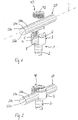
- the stabilization device includes a bone anchoring device 1, a stabilization member in form of a rod 20 and a fixation member 40.
- the bone anchoring device 1 includes a shank 2 that has a bone thread in at least a portion thereof. At one end of the shank 2 a receiving part 3 for receiving the rod 20 is formed.
- the receiving part 3 is designed as a substantially cylindrical part that is fixedly connected to one end of the shank 2 to form a so-called monoaxial bone anchor.
- a recess 4 forming two free legs 5, 6 is provided by means of which a channel for receiving the rod 20 is defined.
- a coaxial bore 7 extends from a free end of the legs 5, 6 to a distance from the free end.
- the coaxial bore 7 is at least partially threaded for permitting the fixation member 40 to be screwed into the bore.
- the channel formed by the legs 5, 6 comprises a base 8 and two opposite sidewalls 9, 10.
- the sidewalls 9, 10 are substantially flat and extend in a substantially vertical direction, i.e. substantially parallel to the shank axis or central axis C of the receiving part 3.
- the distance of the sidewalls 9, 10 and hence, the width of the channel is slightly larger than the largest outer diameter of the rod 20 to be accommodated in the recess 4, so that the rod 20 can be inserted and guided therein in the direction of the rod axis L.
- the base 8 of the recess 4 has a substantially V-shaped cross-section.
- the angle ⁇ is preferably adapted to the shape of the rod 20 as described below.
- the angle ⁇ may be an obtuse angle, i.e. it is greater than 90° and smaller than 180°.
- 10 transition portions 8c may be present that may be rounded or may be flat.
- a coaxial bore 11 may be formed in the center of the channel.
- a circumferentially extending groove 12 for engaging with an instrument for performing surgical steps may be provided on an outer surface of the legs 5, 6 of the receiving part. Furthermore, an undercut 13 may be formed below the thread of the coaxial bore 7 as shown in Figs. 3, 4 and 11 .
- the rod 20 is straight and comprises a rod axis L.
- a plurality of n flat external surfaces 21a, 21b, ..., 21i are formed on the outside of the rod 20. More specifically, in a cross-sectional view, the flat external surfaces lie on the sides of a regular polygon.
- the inside of the rod can be solid.
- the external surfaces 21 a, 21 b, ... ,21i extend along the whole length of the rod 20 and are spaced apart from each other in a circumferential direction at regular distances. Between the flat external surfaces 21a, 21b, ... ,21i intermediate surfaces 22a, 22b ... 22i are formed. The width of the intermediate surfaces 22a, 22b ...
- the intermediate surfaces may be cylindrical or may be flat.
- a cylindrical shape may have an advantage in view of easier rotation of the rod relative to the receiving part 3. In total, there is an equal number n of intermediate surfaces compared to the number n of flat external surfaces.
- the number n of the flat external surfaces 21, 21b, ... ,21i is preferably greater than 3, more preferably an uneven number and more preferably an uneven number greater than 5.
- 9 flat external surfaces are provided. The latter has been found to be suitable for a rod having a largest outer diameter between around 5 mm and around 7 mm.
- the rod 20 has a rotationally symmetrical cross-section in a plane perpendicular to the rod axis L with respect to rotation of the rod around the rod axis L by distinct angles.
- the cross-section of the rod is n-fold rotationally symmetrical around a center point of the cross-sectional plane.
- the rod may be manufactured by starting from a rod with a circular cross-section and treating the outer surface thereof by grinding or cutting to generate the flat external surfaces.
- the fixation member 40 is designed as a set screw that cooperates with the internal thread of the coaxial bore 7 of the legs 5, 6.
- the fixation member 40 comprises a contact surface 41.
- the contact surface 41 is flat in at least a region of the whole surface area that is configured to touch the rod.
- the whole lower surface of the set screw is flat.
- a recess 42 for engagement with a screwing-in tool is provided.
- the fixation member 40 has such a length in an axial direction that when the fixation member 40 is screwed-in between the legs 5, 6 and presses onto the inserted rod 20, the fixation member 40 projects only slightly or does not project out of the receiving part 3.
- the bone anchoring device 1, the fixation member 40 and the rod 20 may be made of bio-compatible materials, for example of titanium or stainless steel, of a bio-compatible alloy, such as a NiTi-alloy, for example Nitinol, of magnesium or magnesium alloys or from a bio-compatible plastic material, such as, for example, polyether ether ketone (PEEK) or poly-1-lactide acid (PLLA).
- a bio-compatible alloy such as a NiTi-alloy, for example Nitinol
- a bio-compatible plastic material such as, for example, polyether ether ketone (PEEK) or poly-1-lactide acid (PLLA).
- PEEK polyether ether ketone
- PLLA poly-1-lactide acid
- At least two bone anchoring devices are inserted into a bone or a vertebra and the rod 20 is inserted into the channel until it rests on the base 8 on the bottom of the receiving part 3. Since consecutive external surfaces 21a, 21b, ... ,21i include an angle ⁇ corresponding to the angle ⁇ of the V-shaped base 8 of the receiving part, the rod 20 will assume when inserted a preferred position such that two adjacent external flat surfaces 21a, 21b, etc., contact the contact surfaces 8a, 8b of the V-shaped base 8.
- the rod 20 is clamped in a form-fit manner at three surface areas, namely at two surface areas established by the contact of the contact surfaces 8a, 8b with the external flat surfaces 21a, 21b and one surface area established by the uppermost external surface 21 f of the rod and the contact surface 41 of the fixation member 40.
- the rod is shown as a straight rod, also curved rods may be provided in the same manner.
- the external surfaces are then curved along the rod axis which has then to be defined infinitesimally for each cross-section of the rod.
- the flat external surfaces may also be provided only on portions of the rod in a lengthwise direction and other portions of the rod may have a circular cross-section.
- the rod can be fixed along three contact areas when such a portion of the rod having the flat external surfaces is placed into the receiving part 3 or it may be used as a rod having a circular cross-section when the portion with the circular cross-section is located into the receiving part 3.
- the intermediate surfaces 22a, 22b ... 22i can also be omitted.
- the rod can have a regular polygonal cross-section.
- the intermediate surfaces can also have another shape.
- the number of flat external surfaces is not limited to an uneven number, it can also be an even number.
- the rod may also have cavities inside, such as a channel, i.e. the rod needs not to be a solid rod.
- the fixation member 40 needs not to have a full flat bottom side. It is sufficient that one flat contact surface exists that cooperates with the uppermost flat external surface 21 f of the rod.
- the rod 20' comprises a plurality of concave external surfaces 21a', 21b' ... 21i'.
- the concave external surfaces 21a', 21b' ... 21 i' correspond to the flat external surfaces of the first embodiment.
- intermediate surfaces 22a', 22b' etc. that may be curved or flat can be present as in the first embodiment.
- the base 8' is also substantially V-shaped and comprises two surfaces 8a', 8b' that are inclined with respect to each other and have convex projections in a cross-sectional view that fit into the concave external surfaces 21a', 21b' of the rod 20'.
- a cylindrical projection 41 a' is provided that is shaped and sized so as to fit in the concave external surface 21 f of the rod 20' that is located on the uppermost side of the rod, when the rod is inserted.
- the modified embodiment provides for an additional form-fit contribution to the rod fixation.
- the stabilization device according to the second embodiment differs from the stabilization device according to the first embodiment by the design of the fixation member. All other parts are identical or highly similar to those of the first embodiment and of the modification of the first embodiment. Hence, also the rod according to the modification of the first embodiment as depicted in Figs. 12 to 14 and all modifications thereof described above can be applied to the stabilization device according to the second embodiment.
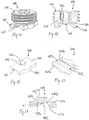
- the fixation member 400 comprises a first fixation member 401 and a second fixation member 410 rotatably connected to the first fixation member 401.
- the first fixation member 401 is designed in the form of a set screw that is configured to cooperate with the internal thread provided on an inner wall of the legs 5, 6.
- the first fixation member 401 has a recess 402 configured to be engaged by a screwing-in tool at the side that is facing away from the second fixation member 410.
- a coaxial bore 403 extends from the bottom of the recess 402 to the lower side 404 of the first fixation member 401.
- the lower side 404 may be formed as a flat surface.
- the second fixation member 410 has a substantially rectangular contour.
- a length of the second fixation member 410 corresponds substantially to a length of the channel formed by the recess 4 of the receiving part 3.
- a width of the second fixation member 410 is only slightly smaller than a width of the recess 4 of the receiving part 3 so that the second fixation member 410 may be inserted into the recess 5 and be guided therein.
- An upper surface 411 of the second fixation member 410 may be flat.
- a projection 412 is provided that may be cylindrical and serves to rotationally engage the first fixation member 401 as shown in Figs. 17 and 18 .
- a rim 413 may be provided that holds the second fixation member 410 in the bore 403 of the first fixation member 401.
- two cylinder segment-shaped bulges 414 may be provided that can engage into the coaxial bore 7 in the receiving part 3.
- a lower side of the second fixation member 410 that faces the rod 20 when the fixation member 400 is in the receiving part 3 comprises a groove 415 that extends in the longitudinal direction of the second fixation member 410.
- the groove 415 has three flat surface portions 415a, 415b and 415c extending in the longitudinal direction.
- the flat surfaces 415a, 415b and 415c form a contour that is adapted to the contour of the outer surface of the rod, i.e. each of the flat surfaces forms a contact surface that engages a corresponding flat external surface of the rod 20.
- two consecutive contact surfaces 415a, 415c or 415c, 415b form an angle ⁇ ' that corresponds to the angle ⁇ formed by the consecutive flat external surfaces of the rod 20.
- intermediate rounded portions 416a, 416b may be formed.
- the second fixation member 410 is moved downward by rotating the first fixation member 401 thereby engaging and clamping the rod 20.
- the second fixation member 410 may also be designed with five contact surfaces or more, thereby increasing the clamping area further. Also, an even number of contact surfaces, for example 2, may be provided on the second fixation member 410 so that the number of external surfaces on the rod in the base that cooperate with the contact surfaces may also be an even number. In the second embodiment, the base in the receiving part may also be flat so as to provide only one contact surface.
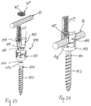
- the third embodiment includes a bone anchoring device that is designed as a polyaxial bone anchor including an outer locking ring.
- the rod 20 corresponds to the rod 20 of the first embodiment. It shall be understood that all modifications of the rod of the first embodiment can be applied also to the stabilization device of the third embodiment.
- the fixation member 400 of the second embodiment may be used.
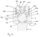
- the polyaxial bone anchoring device 100 comprises a bone anchoring element 101 with a shank 102 and a head 103 having a spherically-shaped outer surface portion.
- the bone anchoring element 101 may be a bone screw with a threaded shank.
- the head 103 may have a recess 104 that serves for engagement with a tool, such as a driver.
- a receiving part 105 is provided for receiving the head 103 and connecting the bone anchoring element 101 via the head 103 to the rod 20.
- the fixation member 40" in the form of a set screw may be provided for fixing the rod 20 in the receiving part 105.
- the bone anchoring device 100 includes a locking ring 107 for locking the head 103 in the receiving part 105.
- the receiving part 105 has an upper end 5a and a lower end 5b. Adjacent to the upper end 5a, a rod receiving portion 150 is provided and adjacent to the lower end 5b a head receiving portion 160 is provided.
- the rod receiving portion 150 is substantially cylindrical and comprises a coaxial bore 151 that extends from the upper end 5a into the head receiving portion 160.
- the bore 151 comprises an internal thread in at least a region thereof for receiving the fixation member 40.
- a substantially U-shaped recess 152 that forms a channel for receiving the rod 20 extends from the upper end 5a to almost the beginning of the head receiving portion 160.
- a groove or otherwise weakened section 153 is provided that allows to break-off the upper portion of the receiving part 105 that serves as extended tabs.
- the extended tabs it is possible to manipulate the polyaxial bone anchoring device with an inserted rod 20 that is positioned at a higher position compared to the final position at the bottom of the recess 152 so that, for example, a vertebra can be pulled against the rod 20.
- the engagement structure may comprise circumferentially extending ribs 154.
- the ribs 154 are arranged asymmetrically with respect to a plane including a central axis C of the receiving part 105 and a channel axis of the substantially U-shaped recess 152. Thereby, a rib-free surface 155 is formed on each side from the U-shaped recess.
- a flat portion 156 is formed in an outer surface of the receiving part 105 for cooperating with the locking ring 107. Furthermore, two cut-outs 157 are formed at the bottom of the channel 152 that is formed by the recess 152. Through the cut-outs 157 a portion of the locking ring 106 can extend.
- the head receiving portion 160 has a substantially cap-like shape with a hollow substantially spherical interior portion 161 for pivotably receiving the head 3 therein.
- a plurality of slits 162 render the head receiving portion 160 flexible so that when pressure is exerted onto the head receiving portion 160 by the locking ring 106, the head 3 can be clamped and finally locked.
- the locking ring 107 is designed to encompass the head receiving portion 160. It has an internal substantially cylindrical section 170 that is configured to compress the head receiving portion 160 to lock the head 103 therein. Further, the locking ring 107 comprises two opposite upstanding sections 171 that may serve for engagement with the receiving part 105 to preliminarily hold the locking ring 106 in an upper position. Moreover, two opposite projections 172 are provided at an upper side of the locking ring 107 that serve for supporting the rod 20. The opposite projections 172 have an upper surface 173 comprising two contact surfaces 173a, 173b that are inclined with respect to each other and that form an angle corresponding to the angle of the flat external surfaces 21 a, 21 b of the rod 20. In other words, the upper surface 173 of the projections 172 forms a base for the rod 20. A circumferential width of the projections 172 is such that the projections 172 can extend through the cut-outs 157 of the rod receiving portion 150.
- the locking ring 107 also comprises two upstanding arms 175 that are asymmetrical with respect to a plane that extends through the central axis C and through the middle of the projections 172 in the same manner as the ribs 154 of the receiving portion 150 are arranged.
- an engagement structure 176 in form of ribs and a groove is provided that is configured to be engaged by an instrument.
- the engagement structure 176 is aligned with the ribs 154 on the receiving part 105 so that the rib-free surface portions 155 of the rod receiving portion 150 are exposed. This may facilitate the application of an instrument.
- the projections 172 extend into the cut-outs 157 and provide a rod support surface 173.
- the fixation member 40" may have a tool engagement recess 42" that extends fully through the fixation member 40".
- a lower contact surface 41" is ring-shaped.
- the receiving part 105 with the pre-assembled locking ring 107 is mounted onto the head 103 of the bone anchoring device 101 so that the head 103 is in the hollow interior 161.
- the rod 20 When the rod 20 is inserted it rests on the base provided by the rod support surface 173.
- the rod 20 presses onto the rod support surface 173 thereby moving the locking ring 107 down.
- the head receiving portion 160 is compressed so that the head 103 is locked.
- the rod is clamped at three surface areas, two on the rod support surface and one on the fixation member 40".
- monoaxial and polyaxial bone anchoring devices are only exemplary and all other types of monoaxial and polyaxial bone anchoring devices can be used, as long as they provide for a rod support surface.
- polyaxial bone anchors with an inner compression member can be used in the same manner.
- the bone anchoring element and/or the shank can have any design that makes it suitable for anchoring in the bone or a vertebra.
Landscapes
- Health & Medical Sciences (AREA)
- Orthopedic Medicine & Surgery (AREA)
- Life Sciences & Earth Sciences (AREA)
- Surgery (AREA)
- Neurology (AREA)
- Heart & Thoracic Surgery (AREA)
- Engineering & Computer Science (AREA)
- Biomedical Technology (AREA)
- Nuclear Medicine, Radiotherapy & Molecular Imaging (AREA)
- Medical Informatics (AREA)
- Molecular Biology (AREA)
- Animal Behavior & Ethology (AREA)
- General Health & Medical Sciences (AREA)
- Public Health (AREA)
- Veterinary Medicine (AREA)
- Surgical Instruments (AREA)
Priority Applications (4)
| Application Number | Priority Date | Filing Date | Title |
|---|---|---|---|
| EP17184814.6A EP3437576B1 (fr) | 2017-08-03 | 2017-08-03 | Dispositif de stabilisation pour os ou vertèbres |
| US16/050,753 US11134991B2 (en) | 2017-08-03 | 2018-07-31 | Stabilization device for bones or vertebrae |
| JP2018143474A JP2019025336A (ja) | 2017-08-03 | 2018-07-31 | 骨または椎骨のための安定化装置 |
| CN201810859821.9A CN109381250A (zh) | 2017-08-03 | 2018-08-01 | 用于骨或椎骨的稳定装置 |
Applications Claiming Priority (1)
| Application Number | Priority Date | Filing Date | Title |
|---|---|---|---|
| EP17184814.6A EP3437576B1 (fr) | 2017-08-03 | 2017-08-03 | Dispositif de stabilisation pour os ou vertèbres |
Publications (2)
| Publication Number | Publication Date |
|---|---|
| EP3437576A1 true EP3437576A1 (fr) | 2019-02-06 |
| EP3437576B1 EP3437576B1 (fr) | 2022-02-09 |
Family
ID=59523030
Family Applications (1)
| Application Number | Title | Priority Date | Filing Date |
|---|---|---|---|
| EP17184814.6A Active EP3437576B1 (fr) | 2017-08-03 | 2017-08-03 | Dispositif de stabilisation pour os ou vertèbres |
Country Status (4)
| Country | Link |
|---|---|
| US (1) | US11134991B2 (fr) |
| EP (1) | EP3437576B1 (fr) |
| JP (1) | JP2019025336A (fr) |
| CN (1) | CN109381250A (fr) |
Cited By (2)
| Publication number | Priority date | Publication date | Assignee | Title |
|---|---|---|---|---|
| WO2022064070A1 (fr) * | 2020-09-28 | 2022-03-31 | Mimeo Medical Gmbh | Dispositif d'ostéosynthèse modulaire et à fixation temporaire pour vertèbres |
| EP4111992A1 (fr) * | 2021-07-01 | 2023-01-04 | Biedermann Technologies GmbH & Co. KG | Dispositif d'ancrage d'os |
Families Citing this family (7)
| Publication number | Priority date | Publication date | Assignee | Title |
|---|---|---|---|---|
| US9259247B2 (en) | 2013-03-14 | 2016-02-16 | Medos International Sarl | Locking compression members for use with bone anchor assemblies and methods |
| FR3035318B1 (fr) * | 2015-04-24 | 2017-05-19 | Medicrea Int | Materiel d'osteosynthese vertebrale |
| CN111728683A (zh) * | 2020-07-15 | 2020-10-02 | 四川大学华西医院 | 椎体嵌入式固定装置 |
| AU2022230734A1 (en) | 2021-03-05 | 2023-10-19 | Medos International Sarl | Multi-feature polyaxial screw |
| US12127766B2 (en) | 2021-03-05 | 2024-10-29 | Medos International Sàrl | Selectively locking polyaxial screw |
| CN115670621B (zh) * | 2022-10-26 | 2026-03-24 | 浙江德康医疗器械有限公司 | 一种仿生微动可调结构的椎弓根螺钉 |
| KR102836394B1 (ko) * | 2023-02-02 | 2025-07-22 | 박경우 | 피로파단 방지를 위한 척추경 고정장치 |
Citations (6)
| Publication number | Priority date | Publication date | Assignee | Title |
|---|---|---|---|---|
| WO2007087476A1 (fr) * | 2006-01-27 | 2007-08-02 | Warsaw Orthopedic, Inc. | Tiges vertébrales ayant des rigidités à la flexion différentes autour d'axes différents et procédés d'utilisation |
| EP1857065A1 (fr) * | 2006-05-16 | 2007-11-21 | BIEDERMANN MOTECH GmbH | Elément longitudinal pour la chirurgie rachidienne ou d'urgence |
| US20070270819A1 (en) * | 2006-04-25 | 2007-11-22 | Justis Jeff R | Surgical instruments and techniques for controlling spinal motion segments with positioning of spinal stabilization elements |
| US20080086130A1 (en) * | 2006-10-06 | 2008-04-10 | Depuy Spine, Inc. | Torsionally stable fixation |
| WO2011006267A1 (fr) * | 2009-07-16 | 2011-01-20 | Spinesave Ag | Dispositif dancrage destiné à une tige de liaison pour stabiliser la colonne vertébrale |
| US8257399B2 (en) | 2007-12-13 | 2012-09-04 | Biedermann Technologies Gmbh & Co. Kg | Anchoring device for anchoring a rod in bones or vertebrae |
Family Cites Families (15)
| Publication number | Priority date | Publication date | Assignee | Title |
|---|---|---|---|---|
| FR2833151B1 (fr) * | 2001-12-12 | 2004-09-17 | Ldr Medical | Implant d'ancrage osseux a tete polyaxiale |
| KR101414716B1 (ko) * | 2006-05-16 | 2014-07-04 | 비이더만 테크놀로지스 게엠베하 & 코. 카게 | 척주 수술 또는 외상 수술에 사용하기 위한 종방향 부재 및이 종방향 부재를 구비한 안정화 장치 |
| US20080051780A1 (en) * | 2006-08-04 | 2008-02-28 | Zimmer Spine, Inc. | Spinal rod connector |
| US7931676B2 (en) * | 2007-01-18 | 2011-04-26 | Warsaw Orthopedic, Inc. | Vertebral stabilizer |
| WO2010030772A1 (fr) * | 2008-09-10 | 2010-03-18 | Life Spine, Inc. | Tige spinale |
| ES2375879T3 (es) * | 2008-12-23 | 2012-03-07 | Biedermann Motech Gmbh | Zona de recepción de una varilla para acoplar la varilla en un elemento de anclaje óseo y dispositivo de anclaje óseo con dicha zona de recepción. |
| EP2384709B1 (fr) * | 2010-05-05 | 2012-09-05 | Biedermann Technologies GmbH & Co. KG | Pièce de réception destinée à recevoir une tige pour coupler la tige à un élément d'ancrage d'os, dispositif d'ancrage d'os, procédé et outil d'assemblage |
| ES2473915T3 (es) * | 2010-12-10 | 2014-07-08 | Biedermann Technologies Gmbh & Co. Kg | Pieza receptora para recibir y alojar una barra con el fin de acoplarla a un elemento de anclaje de hueso y dispositivo de anclaje de hueso con dicha pieza receptora |
| EP2468197B1 (fr) * | 2010-12-23 | 2012-11-21 | Biedermann Technologies GmbH & Co. KG | Dispositif de stabilisation permettant de stabiliser les éléments osseux ou vertèbres |
| EP2574297B1 (fr) * | 2011-09-30 | 2015-11-11 | Biedermann Technologies GmbH & Co. KG | Dispositif d'ancrage d'os et outil fonctionnant avec un tel dispositif d'ancrage d'os |
| EP2591738A1 (fr) * | 2011-11-14 | 2013-05-15 | Biedermann Technologies GmbH & Co. KG | Dispositif polyaxial d'ancrage osseux |
| US9451987B2 (en) * | 2011-11-16 | 2016-09-27 | K2M, Inc. | System and method for spinal correction |
| US8764804B2 (en) * | 2012-09-28 | 2014-07-01 | Warsaw Orthopedic, Inc. | Bone fastener and methods of use |
| US9017386B2 (en) * | 2013-03-08 | 2015-04-28 | Warsaw Orthopedic, Inc. | Iliac connectors |
| EP3120791B1 (fr) * | 2015-07-24 | 2017-11-22 | Biedermann Technologies GmbH & Co. KG | Dispositif d'ancrage osseux polyaxial et instrument destiné à être utilisé avec celui-ci |
-
2017
- 2017-08-03 EP EP17184814.6A patent/EP3437576B1/fr active Active
-
2018
- 2018-07-31 US US16/050,753 patent/US11134991B2/en active Active
- 2018-07-31 JP JP2018143474A patent/JP2019025336A/ja active Pending
- 2018-08-01 CN CN201810859821.9A patent/CN109381250A/zh active Pending
Patent Citations (6)
| Publication number | Priority date | Publication date | Assignee | Title |
|---|---|---|---|---|
| WO2007087476A1 (fr) * | 2006-01-27 | 2007-08-02 | Warsaw Orthopedic, Inc. | Tiges vertébrales ayant des rigidités à la flexion différentes autour d'axes différents et procédés d'utilisation |
| US20070270819A1 (en) * | 2006-04-25 | 2007-11-22 | Justis Jeff R | Surgical instruments and techniques for controlling spinal motion segments with positioning of spinal stabilization elements |
| EP1857065A1 (fr) * | 2006-05-16 | 2007-11-21 | BIEDERMANN MOTECH GmbH | Elément longitudinal pour la chirurgie rachidienne ou d'urgence |
| US20080086130A1 (en) * | 2006-10-06 | 2008-04-10 | Depuy Spine, Inc. | Torsionally stable fixation |
| US8257399B2 (en) | 2007-12-13 | 2012-09-04 | Biedermann Technologies Gmbh & Co. Kg | Anchoring device for anchoring a rod in bones or vertebrae |
| WO2011006267A1 (fr) * | 2009-07-16 | 2011-01-20 | Spinesave Ag | Dispositif dancrage destiné à une tige de liaison pour stabiliser la colonne vertébrale |
Cited By (4)
| Publication number | Priority date | Publication date | Assignee | Title |
|---|---|---|---|---|
| WO2022064070A1 (fr) * | 2020-09-28 | 2022-03-31 | Mimeo Medical Gmbh | Dispositif d'ostéosynthèse modulaire et à fixation temporaire pour vertèbres |
| US12564426B2 (en) | 2020-09-28 | 2026-03-03 | Mimeo Medical Gmbh | Modular and temporarily fixable osteosynthesis device for vertebrae |
| EP4111992A1 (fr) * | 2021-07-01 | 2023-01-04 | Biedermann Technologies GmbH & Co. KG | Dispositif d'ancrage d'os |
| US12171467B2 (en) | 2021-07-01 | 2024-12-24 | Biedermann Technologies Gmbh & Co. Kg | Bone anchoring device |
Also Published As
| Publication number | Publication date |
|---|---|
| EP3437576B1 (fr) | 2022-02-09 |
| JP2019025336A (ja) | 2019-02-21 |
| US11134991B2 (en) | 2021-10-05 |
| US20190038319A1 (en) | 2019-02-07 |
| CN109381250A (zh) | 2019-02-26 |
Similar Documents
| Publication | Publication Date | Title |
|---|---|---|
| EP3437576B1 (fr) | Dispositif de stabilisation pour os ou vertèbres | |
| US11925396B2 (en) | Locking element for a polyaxial bone anchor, bone plate assembly and tool | |
| US9066759B2 (en) | Receiving part for receiving a rod for coupling the rod to a bone anchoring element and a bone anchoring device | |
| US8764805B2 (en) | Stabilization device for stabilizing vertebrae or bone parts | |
| US8192470B2 (en) | Bone anchoring device | |
| US9277942B2 (en) | Polyaxial bone anchoring device with enlarged pivot angle | |
| EP2938278B1 (fr) | Dispositifs de fixation orthopédiques | |
| EP2591740B1 (fr) | Dispositif polyaxial d'ancrage osseux | |
| EP2604204B1 (fr) | Dispositif d'ancrage d'os monoplanaire doté d'un plan d'articulation sélectionnable | |
| EP2851021B1 (fr) | Ensemble de couplage d'une tige à un élément d'ancrage osseux, dispositif d'ancrage osseux polyaxial et dispositif de stabilisation modulaire | |
| EP2559390A1 (fr) | Dispositif d'ancrage d'os polyaxial doté d'un angle de pivot élargi | |
| EP2559391A1 (fr) | Système d'ancrage d'os polyaxial | |
| EP3419537B1 (fr) | Élément de fixation d'os polyaxial | |
| EP4008284A1 (fr) | Dispositif de connexion a utiliser avec les elements d'extension d'un ancrage osseux | |
| EP3730078B1 (fr) | Ensemble de fermeture pour fixer un élément de stabilisation dans une partie réceptrice d'un dispositif d'ancrage d'os | |
| US20160278832A1 (en) | Spine fixation device and spine fixation system |
Legal Events
| Date | Code | Title | Description |
|---|---|---|---|
| PUAI | Public reference made under article 153(3) epc to a published international application that has entered the european phase |
Free format text: ORIGINAL CODE: 0009012 |
|
| STAA | Information on the status of an ep patent application or granted ep patent |
Free format text: STATUS: THE APPLICATION HAS BEEN PUBLISHED |
|
| AK | Designated contracting states |
Kind code of ref document: A1 Designated state(s): AL AT BE BG CH CY CZ DE DK EE ES FI FR GB GR HR HU IE IS IT LI LT LU LV MC MK MT NL NO PL PT RO RS SE SI SK SM TR |
|
| AX | Request for extension of the european patent |
Extension state: BA ME |
|
| STAA | Information on the status of an ep patent application or granted ep patent |
Free format text: STATUS: REQUEST FOR EXAMINATION WAS MADE |
|
| 17P | Request for examination filed |
Effective date: 20190131 |
|
| RBV | Designated contracting states (corrected) |
Designated state(s): AL AT BE BG CH CY CZ DE DK EE ES FI FR GB GR HR HU IE IS IT LI LT LU LV MC MK MT NL NO PL PT RO RS SE SI SK SM TR |
|
| RIC1 | Information provided on ipc code assigned before grant |
Ipc: A61B 17/70 20060101AFI20201130BHEP |
|
| GRAP | Despatch of communication of intention to grant a patent |
Free format text: ORIGINAL CODE: EPIDOSNIGR1 |
|
| STAA | Information on the status of an ep patent application or granted ep patent |
Free format text: STATUS: GRANT OF PATENT IS INTENDED |
|
| INTG | Intention to grant announced |
Effective date: 20210113 |
|
| GRAJ | Information related to disapproval of communication of intention to grant by the applicant or resumption of examination proceedings by the epo deleted |
Free format text: ORIGINAL CODE: EPIDOSDIGR1 |
|
| STAA | Information on the status of an ep patent application or granted ep patent |
Free format text: STATUS: REQUEST FOR EXAMINATION WAS MADE |
|
| INTC | Intention to grant announced (deleted) | ||
| GRAP | Despatch of communication of intention to grant a patent |
Free format text: ORIGINAL CODE: EPIDOSNIGR1 |
|
| STAA | Information on the status of an ep patent application or granted ep patent |
Free format text: STATUS: GRANT OF PATENT IS INTENDED |
|
| INTG | Intention to grant announced |
Effective date: 20210910 |
|
| GRAS | Grant fee paid |
Free format text: ORIGINAL CODE: EPIDOSNIGR3 |
|
| GRAA | (expected) grant |
Free format text: ORIGINAL CODE: 0009210 |
|
| STAA | Information on the status of an ep patent application or granted ep patent |
Free format text: STATUS: THE PATENT HAS BEEN GRANTED |
|
| AK | Designated contracting states |
Kind code of ref document: B1 Designated state(s): AL AT BE BG CH CY CZ DE DK EE ES FI FR GB GR HR HU IE IS IT LI LT LU LV MC MK MT NL NO PL PT RO RS SE SI SK SM TR |
|
| REG | Reference to a national code |
Ref country code: GB Ref legal event code: FG4D |
|
| REG | Reference to a national code |
Ref country code: CH Ref legal event code: EP Ref country code: AT Ref legal event code: REF Ref document number: 1467030 Country of ref document: AT Kind code of ref document: T Effective date: 20220215 |
|
| REG | Reference to a national code |
Ref country code: IE Ref legal event code: FG4D |
|
| REG | Reference to a national code |
Ref country code: DE Ref legal event code: R096 Ref document number: 602017053097 Country of ref document: DE |
|
| REG | Reference to a national code |
Ref country code: LT Ref legal event code: MG9D |
|
| REG | Reference to a national code |
Ref country code: NL Ref legal event code: MP Effective date: 20220209 |
|
| REG | Reference to a national code |
Ref country code: AT Ref legal event code: MK05 Ref document number: 1467030 Country of ref document: AT Kind code of ref document: T Effective date: 20220209 |
|
| PG25 | Lapsed in a contracting state [announced via postgrant information from national office to epo] |
Ref country code: SE Free format text: LAPSE BECAUSE OF FAILURE TO SUBMIT A TRANSLATION OF THE DESCRIPTION OR TO PAY THE FEE WITHIN THE PRESCRIBED TIME-LIMIT Effective date: 20220209 Ref country code: RS Free format text: LAPSE BECAUSE OF FAILURE TO SUBMIT A TRANSLATION OF THE DESCRIPTION OR TO PAY THE FEE WITHIN THE PRESCRIBED TIME-LIMIT Effective date: 20220209 Ref country code: PT Free format text: LAPSE BECAUSE OF FAILURE TO SUBMIT A TRANSLATION OF THE DESCRIPTION OR TO PAY THE FEE WITHIN THE PRESCRIBED TIME-LIMIT Effective date: 20220609 Ref country code: NO Free format text: LAPSE BECAUSE OF FAILURE TO SUBMIT A TRANSLATION OF THE DESCRIPTION OR TO PAY THE FEE WITHIN THE PRESCRIBED TIME-LIMIT Effective date: 20220509 Ref country code: NL Free format text: LAPSE BECAUSE OF FAILURE TO SUBMIT A TRANSLATION OF THE DESCRIPTION OR TO PAY THE FEE WITHIN THE PRESCRIBED TIME-LIMIT Effective date: 20220209 Ref country code: LT Free format text: LAPSE BECAUSE OF FAILURE TO SUBMIT A TRANSLATION OF THE DESCRIPTION OR TO PAY THE FEE WITHIN THE PRESCRIBED TIME-LIMIT Effective date: 20220209 Ref country code: HR Free format text: LAPSE BECAUSE OF FAILURE TO SUBMIT A TRANSLATION OF THE DESCRIPTION OR TO PAY THE FEE WITHIN THE PRESCRIBED TIME-LIMIT Effective date: 20220209 Ref country code: ES Free format text: LAPSE BECAUSE OF FAILURE TO SUBMIT A TRANSLATION OF THE DESCRIPTION OR TO PAY THE FEE WITHIN THE PRESCRIBED TIME-LIMIT Effective date: 20220209 Ref country code: BG Free format text: LAPSE BECAUSE OF FAILURE TO SUBMIT A TRANSLATION OF THE DESCRIPTION OR TO PAY THE FEE WITHIN THE PRESCRIBED TIME-LIMIT Effective date: 20220509 |
|
| PG25 | Lapsed in a contracting state [announced via postgrant information from national office to epo] |
Ref country code: PL Free format text: LAPSE BECAUSE OF FAILURE TO SUBMIT A TRANSLATION OF THE DESCRIPTION OR TO PAY THE FEE WITHIN THE PRESCRIBED TIME-LIMIT Effective date: 20220209 Ref country code: LV Free format text: LAPSE BECAUSE OF FAILURE TO SUBMIT A TRANSLATION OF THE DESCRIPTION OR TO PAY THE FEE WITHIN THE PRESCRIBED TIME-LIMIT Effective date: 20220209 Ref country code: GR Free format text: LAPSE BECAUSE OF FAILURE TO SUBMIT A TRANSLATION OF THE DESCRIPTION OR TO PAY THE FEE WITHIN THE PRESCRIBED TIME-LIMIT Effective date: 20220510 Ref country code: FI Free format text: LAPSE BECAUSE OF FAILURE TO SUBMIT A TRANSLATION OF THE DESCRIPTION OR TO PAY THE FEE WITHIN THE PRESCRIBED TIME-LIMIT Effective date: 20220209 Ref country code: AT Free format text: LAPSE BECAUSE OF FAILURE TO SUBMIT A TRANSLATION OF THE DESCRIPTION OR TO PAY THE FEE WITHIN THE PRESCRIBED TIME-LIMIT Effective date: 20220209 |
|
| PG25 | Lapsed in a contracting state [announced via postgrant information from national office to epo] |
Ref country code: IS Free format text: LAPSE BECAUSE OF FAILURE TO SUBMIT A TRANSLATION OF THE DESCRIPTION OR TO PAY THE FEE WITHIN THE PRESCRIBED TIME-LIMIT Effective date: 20220609 |
|
| PG25 | Lapsed in a contracting state [announced via postgrant information from national office to epo] |
Ref country code: SM Free format text: LAPSE BECAUSE OF FAILURE TO SUBMIT A TRANSLATION OF THE DESCRIPTION OR TO PAY THE FEE WITHIN THE PRESCRIBED TIME-LIMIT Effective date: 20220209 Ref country code: SK Free format text: LAPSE BECAUSE OF FAILURE TO SUBMIT A TRANSLATION OF THE DESCRIPTION OR TO PAY THE FEE WITHIN THE PRESCRIBED TIME-LIMIT Effective date: 20220209 Ref country code: RO Free format text: LAPSE BECAUSE OF FAILURE TO SUBMIT A TRANSLATION OF THE DESCRIPTION OR TO PAY THE FEE WITHIN THE PRESCRIBED TIME-LIMIT Effective date: 20220209 Ref country code: EE Free format text: LAPSE BECAUSE OF FAILURE TO SUBMIT A TRANSLATION OF THE DESCRIPTION OR TO PAY THE FEE WITHIN THE PRESCRIBED TIME-LIMIT Effective date: 20220209 Ref country code: DK Free format text: LAPSE BECAUSE OF FAILURE TO SUBMIT A TRANSLATION OF THE DESCRIPTION OR TO PAY THE FEE WITHIN THE PRESCRIBED TIME-LIMIT Effective date: 20220209 Ref country code: CZ Free format text: LAPSE BECAUSE OF FAILURE TO SUBMIT A TRANSLATION OF THE DESCRIPTION OR TO PAY THE FEE WITHIN THE PRESCRIBED TIME-LIMIT Effective date: 20220209 |
|
| REG | Reference to a national code |
Ref country code: DE Ref legal event code: R097 Ref document number: 602017053097 Country of ref document: DE |
|
| PG25 | Lapsed in a contracting state [announced via postgrant information from national office to epo] |
Ref country code: AL Free format text: LAPSE BECAUSE OF FAILURE TO SUBMIT A TRANSLATION OF THE DESCRIPTION OR TO PAY THE FEE WITHIN THE PRESCRIBED TIME-LIMIT Effective date: 20220209 |
|
| PLBE | No opposition filed within time limit |
Free format text: ORIGINAL CODE: 0009261 |
|
| STAA | Information on the status of an ep patent application or granted ep patent |
Free format text: STATUS: NO OPPOSITION FILED WITHIN TIME LIMIT |
|
| 26N | No opposition filed |
Effective date: 20221110 |
|
| PG25 | Lapsed in a contracting state [announced via postgrant information from national office to epo] |
Ref country code: SI Free format text: LAPSE BECAUSE OF FAILURE TO SUBMIT A TRANSLATION OF THE DESCRIPTION OR TO PAY THE FEE WITHIN THE PRESCRIBED TIME-LIMIT Effective date: 20220209 |
|
| PG25 | Lapsed in a contracting state [announced via postgrant information from national office to epo] |
Ref country code: MC Free format text: LAPSE BECAUSE OF FAILURE TO SUBMIT A TRANSLATION OF THE DESCRIPTION OR TO PAY THE FEE WITHIN THE PRESCRIBED TIME-LIMIT Effective date: 20220209 |
|
| PG25 | Lapsed in a contracting state [announced via postgrant information from national office to epo] |
Ref country code: LU Free format text: LAPSE BECAUSE OF NON-PAYMENT OF DUE FEES Effective date: 20220803 |
|
| REG | Reference to a national code |
Ref country code: BE Ref legal event code: MM Effective date: 20220831 |
|
| P01 | Opt-out of the competence of the unified patent court (upc) registered |
Effective date: 20230525 |
|
| PG25 | Lapsed in a contracting state [announced via postgrant information from national office to epo] |
Ref country code: IT Free format text: LAPSE BECAUSE OF FAILURE TO SUBMIT A TRANSLATION OF THE DESCRIPTION OR TO PAY THE FEE WITHIN THE PRESCRIBED TIME-LIMIT Effective date: 20220209 Ref country code: IE Free format text: LAPSE BECAUSE OF NON-PAYMENT OF DUE FEES Effective date: 20220803 Ref country code: FR Free format text: LAPSE BECAUSE OF NON-PAYMENT OF DUE FEES Effective date: 20220831 |
|
| PG25 | Lapsed in a contracting state [announced via postgrant information from national office to epo] |
Ref country code: BE Free format text: LAPSE BECAUSE OF NON-PAYMENT OF DUE FEES Effective date: 20220831 |
|
| PG25 | Lapsed in a contracting state [announced via postgrant information from national office to epo] |
Ref country code: HU Free format text: LAPSE BECAUSE OF FAILURE TO SUBMIT A TRANSLATION OF THE DESCRIPTION OR TO PAY THE FEE WITHIN THE PRESCRIBED TIME-LIMIT; INVALID AB INITIO Effective date: 20170803 |
|
| PG25 | Lapsed in a contracting state [announced via postgrant information from national office to epo] |
Ref country code: MK Free format text: LAPSE BECAUSE OF FAILURE TO SUBMIT A TRANSLATION OF THE DESCRIPTION OR TO PAY THE FEE WITHIN THE PRESCRIBED TIME-LIMIT Effective date: 20220209 Ref country code: CY Free format text: LAPSE BECAUSE OF FAILURE TO SUBMIT A TRANSLATION OF THE DESCRIPTION OR TO PAY THE FEE WITHIN THE PRESCRIBED TIME-LIMIT Effective date: 20220209 |
|
| PG25 | Lapsed in a contracting state [announced via postgrant information from national office to epo] |
Ref country code: MT Free format text: LAPSE BECAUSE OF FAILURE TO SUBMIT A TRANSLATION OF THE DESCRIPTION OR TO PAY THE FEE WITHIN THE PRESCRIBED TIME-LIMIT Effective date: 20220209 |
|
| PGFP | Annual fee paid to national office [announced via postgrant information from national office to epo] |
Ref country code: DE Payment date: 20250827 Year of fee payment: 9 |
|
| PGFP | Annual fee paid to national office [announced via postgrant information from national office to epo] |
Ref country code: GB Payment date: 20250819 Year of fee payment: 9 |
|
| PGFP | Annual fee paid to national office [announced via postgrant information from national office to epo] |
Ref country code: CH Payment date: 20250901 Year of fee payment: 9 |
|
| PG25 | Lapsed in a contracting state [announced via postgrant information from national office to epo] |
Ref country code: TR Free format text: LAPSE BECAUSE OF FAILURE TO SUBMIT A TRANSLATION OF THE DESCRIPTION OR TO PAY THE FEE WITHIN THE PRESCRIBED TIME-LIMIT Effective date: 20220209 |