EP3437664A1 - Procédé de stérilisation - Google Patents
Procédé de stérilisation Download PDFInfo
- Publication number
- EP3437664A1 EP3437664A1 EP18194063.6A EP18194063A EP3437664A1 EP 3437664 A1 EP3437664 A1 EP 3437664A1 EP 18194063 A EP18194063 A EP 18194063A EP 3437664 A1 EP3437664 A1 EP 3437664A1
- Authority
- EP
- European Patent Office
- Prior art keywords
- pressure
- container
- residual water
- water
- time
- Prior art date
- Legal status (The legal status is an assumption and is not a legal conclusion. Google has not performed a legal analysis and makes no representation as to the accuracy of the status listed.)
- Withdrawn
Links
Images








Classifications
-
- A—HUMAN NECESSITIES
- A23—FOODS OR FOODSTUFFS; TREATMENT THEREOF, NOT COVERED BY OTHER CLASSES
- A23B—PRESERVATION OF FOODS, FOODSTUFFS OR NON-ALCOHOLIC BEVERAGES; CHEMICAL RIPENING OF FRUIT OR VEGETABLES
- A23B5/00—Preservation of eggs or egg products
- A23B5/02—Drying; Subsequent reconstitution
- A23B5/022—Drying with use of gas or vacuum
-
- A—HUMAN NECESSITIES
- A61—MEDICAL OR VETERINARY SCIENCE; HYGIENE
- A61L—METHODS OR APPARATUS FOR STERILISING MATERIALS OR OBJECTS IN GENERAL; DISINFECTION, STERILISATION OR DEODORISATION OF AIR; CHEMICAL ASPECTS OF BANDAGES, DRESSINGS, ABSORBENT PADS OR SURGICAL ARTICLES; MATERIALS FOR BANDAGES, DRESSINGS, ABSORBENT PADS OR SURGICAL ARTICLES
- A61L2/00—Disinfection or sterilisation of materials or objects, in general; Accessories therefor
- A61L2/16—Disinfection or sterilisation of materials or objects, in general; Accessories therefor using chemical substances
- A61L2/20—Gaseous substances, e.g. vapours
-
- A—HUMAN NECESSITIES
- A23—FOODS OR FOODSTUFFS; TREATMENT THEREOF, NOT COVERED BY OTHER CLASSES
- A23B—PRESERVATION OF FOODS, FOODSTUFFS OR NON-ALCOHOLIC BEVERAGES; CHEMICAL RIPENING OF FRUIT OR VEGETABLES
- A23B2/00—Preservation of foods or foodstuffs, in general
- A23B2/10—Preservation of foods or foodstuffs, in general by treatment with pressure variation, shock, acceleration or shear stress
-
- A—HUMAN NECESSITIES
- A23—FOODS OR FOODSTUFFS; TREATMENT THEREOF, NOT COVERED BY OTHER CLASSES
- A23B—PRESERVATION OF FOODS, FOODSTUFFS OR NON-ALCOHOLIC BEVERAGES; CHEMICAL RIPENING OF FRUIT OR VEGETABLES
- A23B2/00—Preservation of foods or foodstuffs, in general
- A23B2/70—Preservation of foods or foodstuffs, in general by treatment with chemicals
-
- A—HUMAN NECESSITIES
- A23—FOODS OR FOODSTUFFS; TREATMENT THEREOF, NOT COVERED BY OTHER CLASSES
- A23B—PRESERVATION OF FOODS, FOODSTUFFS OR NON-ALCOHOLIC BEVERAGES; CHEMICAL RIPENING OF FRUIT OR VEGETABLES
- A23B7/00—Preservation of fruit or vegetables; Chemical ripening of fruit or vegetables
- A23B7/02—Dehydrating; Subsequent reconstitution
-
- A—HUMAN NECESSITIES
- A23—FOODS OR FOODSTUFFS; TREATMENT THEREOF, NOT COVERED BY OTHER CLASSES
- A23B—PRESERVATION OF FOODS, FOODSTUFFS OR NON-ALCOHOLIC BEVERAGES; CHEMICAL RIPENING OF FRUIT OR VEGETABLES
- A23B9/00—Preservation of edible seeds, e.g. cereals
- A23B9/08—Drying; Subsequent reconstitution
-
- A—HUMAN NECESSITIES
- A61—MEDICAL OR VETERINARY SCIENCE; HYGIENE
- A61L—METHODS OR APPARATUS FOR STERILISING MATERIALS OR OBJECTS IN GENERAL; DISINFECTION, STERILISATION OR DEODORISATION OF AIR; CHEMICAL ASPECTS OF BANDAGES, DRESSINGS, ABSORBENT PADS OR SURGICAL ARTICLES; MATERIALS FOR BANDAGES, DRESSINGS, ABSORBENT PADS OR SURGICAL ARTICLES
- A61L2/00—Disinfection or sterilisation of materials or objects, in general; Accessories therefor
- A61L2/16—Disinfection or sterilisation of materials or objects, in general; Accessories therefor using chemical substances
-
- A—HUMAN NECESSITIES
- A23—FOODS OR FOODSTUFFS; TREATMENT THEREOF, NOT COVERED BY OTHER CLASSES
- A23V—INDEXING SCHEME RELATING TO FOODS, FOODSTUFFS OR NON-ALCOHOLIC BEVERAGES AND LACTIC OR PROPIONIC ACID BACTERIA USED IN FOODSTUFFS OR FOOD PREPARATION
- A23V2002/00—Food compositions, function of food ingredients or processes for food or foodstuffs
-
- A—HUMAN NECESSITIES
- A61—MEDICAL OR VETERINARY SCIENCE; HYGIENE
- A61L—METHODS OR APPARATUS FOR STERILISING MATERIALS OR OBJECTS IN GENERAL; DISINFECTION, STERILISATION OR DEODORISATION OF AIR; CHEMICAL ASPECTS OF BANDAGES, DRESSINGS, ABSORBENT PADS OR SURGICAL ARTICLES; MATERIALS FOR BANDAGES, DRESSINGS, ABSORBENT PADS OR SURGICAL ARTICLES
- A61L2/00—Disinfection or sterilisation of materials or objects, in general; Accessories therefor
- A61L2/24—Apparatus using programmed or automatic operation
Definitions
- the present invention relates to a method for sterilizing an object under pressure within a container using a sterilant and a sterilizer using the method.
- Conventional well-known method for sterilizing an object such as medical instrument includes applying heat or pressure from a source of high pressure steam, dry heat, electromagnetic radiation, hydrogen peroxide, gas plasma, or EOG gas.
- the conventional method may be inapplicable to the object which can be damaged by heat or pressure.
- the high pressure steam or the high temperature dry heat may be inapplicable to some objects.
- the electromagnetic radiation may be inapplicable to other objects such as hollow metal or plastic composite material.
- the EOG gas sterilization may be applicable to any object irrespective of its material, it needs a considerable time for aeration procedures for the purpose of toxicity removal, which decreases the operational availability of the practical sterilizer.
- One conventional solution that may solve those problems is a gas plasma sterilization method.
- the method uses a sterilant containing hydrogen peroxide which is brought into contact with every surface portion of the object which has been washed and then dried completely.
- One known drying technique which may be used in the plasma gas sterilization is placing the object in a sterilization container, decompressing the interior of the container to vaporize residual water on the object, and then pumping to exhaust the generated vapor into the atmosphere and thereby to dry the object and the interior of the container.
- Patent Document 1 discloses a sterilization method using the technique, in which the interior of the object containing container is decompressed to about 40 to 200 Pa which is considered to be most advantageous for the generation of plasma within the container to vaporize the residual water on the object. Specifically, in this process, the vaporization of the residual water on the object loses its calories. Then, the object is heated at the generation of plasma within the interior of the container at a reduced pressure of about 40 to 200 Pa. Further, heat is transferred from the high-temperature container to the object through air introduced at the restoring of the pressure in the container to an atmospheric pressure or a quasi-atmospheric pressure (pressure which is close to the atmospheric pressure), increasing the temperature of the object and the residual water. Subsequently, a process for depressurizing the interior of the container to about 40 to 133 Pa and thereby to vaporize the residual water on the object is repeated at least twice.
- Patent Document 1 JP 4526649 B2
- Non-patent Document 1 Rika YOSHIDA et al, "Hydrogen Peroxide Vapour in the Proximity of Hydrogen Peroxide Sterilisers", Jpn J Environment Infect, vol. 26, no.4; p239-242, 2011
- Non-Patent Document 1 to remove the residual sterilant is one of the drawbacks which should be solved practically.
- Another problem associated with the plasma gas sterilization may be that the residual water in the sterilization container loses its calories due to its vaporization caused at the drying of the object, which may provide an adverse effect on the drying of the object by the decompression boiling.
- the above-described drying technique employed in the conventional sterilization method using the agent may be effective for the objects with little residual water and without deep concaved portion.
- the water retained in the deep concaved portions may be extracted therefrom and vaporized in the course of the first decompressing process.
- the pressure in the container is reduced to less than about 670 Pa, most preferably about 40 to 200 Pa to vaporize the residual water.
- some water may not be vaporized to remain on the object even in a pressure less than the triple point of water, i.e., 610 Pa. Under such pressure, the temperature of the residual water is less than its freezing point, causing the water to freeze into ice which may block the residual water in the concaved portions from being evaporated to remain on the object.
- the above sterilization method decompresses, without interruption, the interior of the container to about 40 to 200 Pa which is most preferable for the plasma generation, through the triple point of water, which may freeze the residual water presenting in the concaved portions or at their entrances. Therefore, the incoming air which is introduced into the container for recovering the pressure in the container to the atmospheric pressure or quasi-atmospheric pressure may not be served for heating the object because it is blocked by the frozen water presenting in the concaved portions or at their entrances, which in turn result in an insufficient drying of the object.
- a major object of the invention is to increase a contact efficiency of the sterilant in the sterilization process in which the interior of the container is decompressed and thereby to sterilize the object by the contact with the introduced sterilant, and to minimize or eliminate a residual sterilant in the container after the sterilization process.
- a first aspect of the present invention relates to a method for sterilizing an object in a container using a sterilant, the method including the steps of:
- the method according to the first aspect of the present invention may further include comprising the step (A6) of determining whether residual water exists in the container after the step (A2), wherein the steps (A3), (A1), (A2) and (A6) are performed in this order if it is determined in the step (A6) that the residual water exists, and wherein the steps (A4) and (A5) are performed in this order if it is determined in the step (A6) that the residual water does not exist.
- whether the residual water exists may be determined in the step (A6) based on an actual time in which the pressure in the container is decreased to the first pressure. Also, the step (A6) may comprise comparing a reference time stored in a memory and the actual time, and wherein, if the actual time is equal to or less than the reference time, it is determined that no residual water exists.
- a second aspect of the present invention relates to a method for sterilizing an object in a container using a sterilant, the method including the steps of:
- whether the residual water exists in the container may be determined in the step (B6) based on a rate of pressure increase per unit time in the step (B2).
- the step (B6) may include comparing a reference rate of pressure increase stored in a memory and the actual rate of pressure increase, and wherein, if the actual rate of pressure increase is equal to or less than the reference rate of pressure increase, it is determined that no residual water exists.
- a third aspect of the present invention relates to a sterilizer for sterilizing an object in a container using a sterilant, the sterilizer including:
- a fourth aspect of the present invention relates to a sterilizer for sterilizing an object in a container using a sterilant, the sterilizer including:
- One aspect of the present invention relates to a method for sterilizing an object in a container using a sterilant, the method comprising the steps of:
- the method according to the present invention enables the residual water, which is impregnated onto the object to be sterilized during the pre-washing, to be efficiently and certainly drained away before the sterilant injection. Further, the method enables the residual water to be drained away while the pressure is maintained which is equal to or higher than the triple point pressure at which water freezes, during the pressure decreasing process, thereby determining the existence of the residual water. If the residual water exists, the pressure in the container is increased to the atmospheric pressure or the quasi-atmospheric pressure and the object is heated to drain away the residual water. Further, these steps are repeated until that the object does not include the residual water thereon is determined, the pressure is decreased to a pressure which is lower than the triple point pressure at which water freezes and subsequently the sterilant is injected into the container for sterilization.
- the pressure increasing/decreasing process is repeated between the atmospheric pressure (or the quasi-atmospheric pressure) and the pressure which is equal to or higher than the triple point pressure of water for the purpose of drying the inside of the container which accommodates the object to be sterilized therein, the period of time required for the pressure decreasing process is used to determine the inside of the container is adequately dried, and subsequently the pressure is decreased to the pressure which is lower than the triple point pressure to inject the sterilant into the container, thereby increasing the contact efficiency of the sterilant and minimizing or eliminating the residual sterilant in the container after the sterilization process.
- the reference time for decreasing the pressure is used to determine the inside of the container is adequately dried and thereby to determine the existence of the residual water without complete measurements and/or calculations, in a case where the same instruments are used.
- the pressure increasing/decreasing process is repeated between the atmospheric pressure (or the quasi-atmospheric pressure) and the pressure which is equal to or higher than the triple point pressure of water for the purpose of drying the inside of the container which accommodates the object to be sterilized therein
- the actual rate of pressure increase measured during the pressure increasing process may be compared with the reference rate to determine the inside of the container is adequately dried, and subsequently the pressure is decreased to the pressure which is lower than the triple point pressure to inject the sterilant into the container, thereby increasing the contact efficiency of the sterilant and minimizing or eliminating the residual sterilant in the container after the sterilization process.
- the reference rate of pressure increase is used to determine the inside of the container is adequately dried and thereby to determine the existence of the residual water without complete measurements and/or calculations, in a case where the same instruments are used and free of influence from the operating condition of a pump used for decreasing the pressure.
- the pressure increasing/decreasing process is repeated between the atmospheric pressure (or the quasi-atmospheric pressure) and the pressure which is equal to or higher than the triple point pressure of water for the purpose of drying the inside of the container which accommodates the object to be sterilized therein, the period of time required for the pressure decreasing process is used to determine the inside of the container is adequately dried, and subsequently the pressure is decreased to the pressure which is lower than the triple point pressure to inject the sterilant into the container, thereby increasing the contact efficiency of the sterilant and minimizing or eliminating the residual sterilant in the container after the sterilization process.
- the apparatus according to the third aspect of the present invention enables the residual water, which is impregnated onto the object to be sterilized during the pre-washing, to be efficiently and certainly drained away before the sterilant injection. This enables the drying process with a shorter time without any heating process or the heated gas and thereby the gas can be used for drying the object which can be damaged by heat or pressure without causing any problems. Further, the apparatus does not require an inflowing means for inflowing warm or hot air into the container, avoiding causing the system of the sterilizer in its entirety become complicated and/or huge.
- the pressure increasing/decreasing process is repeated between the atmospheric pressure (or the quasi-atmospheric pressure) and the pressure which is equal to or higher than the triple point pressure of water for the purpose of drying the inside of the container which accommodates the object to be sterilized therein
- the actual rate of pressure increase measured during the pressure increasing process may be compared with the reference rate to determine the inside of the container is adequately dried, and subsequently the pressure is decreased to the pressure which is lower than the triple point pressure to inject the sterilant into the container, thereby increasing the contact efficiency of the sterilant and minimizing or eliminating the residual sterilant in the container after the sterilization process.
- the apparatus according to the fourth aspect of the present invention enables the residual water, which is impregnated onto the object to be sterilized during the pre-washing, to be efficiently and certainly drained away before the sterilant injection. This enables the drying process with a shorter time without any heating process or the heated gas and thereby the gas can be used for drying the object which can be damaged by heat or pressure without causing any problems. Further, the apparatus does not require an inflowing means for inflowing warm or hot air into the container, avoiding causing the system of the sterilizer in its entirety become complicated and/or huge.
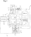
- Fig. 1 is a block diagram schematically showing a sterilizer in its entirety according to an embodiment of the present invention.
- the sterilizer 1 which is referred to as simply “apparatus” as necessary, is designed to sterilize the object 2 by using a sterilant within an adequately decompressed container 11.
- the sterilizer 1 includes a sterilant supply system 6, a sterilization system 10, an intake/exhaust piping system 15 for controlling an air into and out of the container 11, and a controller 23 which controls the sterilizer 1 in its entirety.
- the sterilant supply system 6 includes a tank 7 which reserves the sterilant, a sterilant injector 8, and a sterilant injection solenoid valve 9.
- the sterilant injector 8 is configured to measure an appropriate quantity of the sterilant to supply it into the container 11 after the solenoid valve 9 is opened in response to a control signal from the controller 23.
- the sterilization system 10 includes the container 11 having an internal box 12 mounted therein for accommodating the object 2 to be sterilized.
- the system 10 further includes a high-frequency generator 13 provided outside the container 11 for generating plasma within an interior of the container 11, and a pressure measuring unit 14 for measuring a pressure in the container 11.
- the container 11 is fluidly connected to the sterilant supply system 6 and the intake/exhaust piping system 15.
- the container 11 and its internal box 12 are each made of electrically conductive material having a certain strength, stiffness and corrosion resistance.
- the container 11 and the internal box 12 are electrically insulated each other.
- the container 11 serving as an external box and the internal box 12 each may be made of a metal plate such as a steel plate.
- the container or external box 11 is formed by bending and machining a commonly-used metal plate to form the air-tightly sealable interior inside the internal box.
- the internal box 12 is formed by bending and machining a perforated metal plate or a metal plate having many perforations so that the vaporized sterilant or fluid such as air or gaseous plasma can freely move between the interior and the exterior of the internal box 12.
- the high-frequency generator 13 which serves as a plasma generator, is disposed outside of the container 11.
- the high-frequency generator 13 may include a high-frequency circuit and a high-frequency power source.
- the intake/exhaust piping system 15 includes an intake piping system 16 through which an atmospheric air is introduced into the container 11 and an exhaust piping system 19 through which the air in the container 11 is exhausted to the outside thereof.
- the intake piping system 16 includes an air filter 17 which purifies the atmospheric air when it is introduced into the container 11 and an introduction solenoid valve 18 which is opened for the introduction of the atmospheric air.
- the exhaust piping system 19 includes an air displacement pump 20 which evacuates the container 11, and a solenoid valve 21 which is opened for the evacuation.
- This arrangement allows that the atmospheric air is cleaned by the air filter 17 located at the upstream side of the solenoid valve 18 as it is introduced into the container 11 in response to a control signal from the controller 23. Likewise, the atmosphere in the container 11 is cleaned by an exhaust gas filter 22 located at the downstream side of the air displacement pump 20 as it is evacuated in response to a control signal from the controller 23.
- the controller 23, which controls the sterilizer 1 in its entirety, has a microcomputer as a main component.
- the controller 23 may be mounted on a control panel (not shown).
- the sterilant injector 8 and the solenoid valve 9 in the sterilant supply system 6, the high-frequency generator 13 and the pressure measuring unit 14 in the sterilization system 10, the solenoid valve for introducing the atmospheric air 18, the air displacement pump 20 and the solenoid valve 21 in the intake/exhaust piping system 15 are each connected for signal transmission and reception to the controller 23 so that they are controlled by control signals received from the controller 23.
- Each of the solenoid valves 9, 18 and 21 may be any one of conventional electromagnetic control valves.
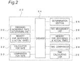
- Fig. 2 is a block diagram showing the controller 23 of the sterilizer 1 shown in Fig. 1 in detail.
- pressures and temperatures are denoted by reference signs such as P101, T101 illustrated in Figs. 5 to 8 and Figs. 13 to 16 for the better understanding of the operation.
- the controller 23 of the sterilizer 1 includes a residual water determining unit/section 25 which determines the existence of a residual water, a time measurement unit 26 which measures an actual time T101 spent for decreasing the pressure in the container to a predetermined first pressure P101, a memory 27 which stores a reference time T101a which is a reference value for decreasing the pressure to the first pressure P101 and the actual time T101, and a time comparator 28 which compares the actual time T101 with the reference time T101a stored in the memory 27.
- the units 25 to 28 are connected for signal transmission and reception to the operator 24.
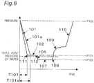
- the period of time T101 a which is the reference time for decreasing the pressure in the container 11 to the first pressure P101, corresponds to a period of time for decreasing the pressure in the container 11 to the first pressure P101 in the pressure decreasing step 101a described below when no residual water is detected on the object 2.
- the controller 23 includes a time calculating unit 29 which calculates a time difference in the pressure decrease, stored in the memory 27, which may be caused due to the variation of the first pressure P101, a pressure increasing rate determining unit 30 which measures a rate of pressure increase from the first pressure P101, a memory 31 which stores a reference rate of pressure increase Rp114a and an actual rate of pressure increase Rp114, a calculator 32 which calculates a rate of pressure increase per unit time, and a comparator 33 which compares the reference rate of pressure increase Rp114a with the actual rate of pressure increase Rp114.
- the units 29 to 33 are connected for signal transmission and reception to the operator 24.
- the reference rate of pressure increase Rp114a is a reference value for increasing the pressure from the first pressure P101.
- the reference rate of pressure increase Rp114a further corresponds to a rate of pressure increase for increasing the pressure from the first pressure P101 when no residual water is detected on the object 2 to be sterilized.
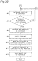
- Figs. 3A to 3C are flowcharts illustrating the operation of the sterilizer according to the first embodiment of the present invention.
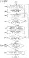
- step #1 the object 2 to be sterilized is accommodated in the internal box 12 of the container 11.
- step #2 the air displacement pump 20 is energized to decrease the pressure in the container 11.
- step #3 a determination is made whether the pressure in the container 11 reaches the first pressure P101 which is equal to or higher than the triple point pressure of water.
- the pressure in the container 11 is measured by the pressure measuring unit 14, and the measurement is transmitted to the controller 23. Based on the output signal from the operator 24 of the controller 23, the displacement pump 20 and the solenoid valve 21 are controlled so that the pressure in the container 11 is decreased to the target pressure, i.e., the first pressure P101. If it is determined that the pressure in the container 11 reaches the first pressure P101, the pressure in the container 11 is maintained at the first pressure P101 for a certain period of time.
- the time measurement unit 26 measures the actual time T101 required for the pressure in the container to reach the first pressure P101 from the beginning of the pressure reduction control.
- the measured actual time T101 is stored in the memory 27.
- the air displacement pump 20 is deactivated and the solenoid valve 21 is closed, for a certain period of time.
- step #4 as described above, the air displacement pump 20 is activated again and the solenoid valve 21 is controlled so that the pressure in the container 11 is maintained at the first pressure P101 for a certain period of time T102.
- step #5 a comparison is made between the reference time T101a stored in the memory 27 and the actual time.
- the reference time T101 a is the reference value for decreasing the pressure in the container 11 to the first pressure P101 and corresponds to a period of time for decreasing the pressure in the container 11 to the first pressure P101 when no residual water is detected on the object 2 in the pressure decreasing step 101a.
- the actual time T101 is the period of time for actually decreasing the pressure in the container 11 to the first pressure P101.
- the actual time T101 and the reference time T101a are adjusted by using a difference between the pressures inside and outside the container at the beginning of the pressure decreasing operation at the time calculating unit 29. Then, the determination section 25 uses the adjusted time to determine whether T101 is equal to or less than T101a, i.e., T101 ⁇ T101a. The result is used to determine the existence of residual water on the object 2 to be sterilized.
- step #5 If it is determined in step #5 that no residual water exists on the object 2, the displacement pump 20 and the solenoid valve 21 are controlled to decrease the pressure in the container 11. If it is determined in step #7 that the pressure in the container 11 is decreased to the third pressure P103 which is lower than the triple point pressure of water, the pressure in the third pressure in the container 11 is maintained at the third pressure for a certain period of time. After the elapse of the time, in step #9 the sterilant is injected into the container 11. The condition in the container 11 is maintained for a certain period of time, and then plasma is generated within the container 11 in step #10. Then, in step #11 the pressure in the container 11 is increased to the second pressure P102. Next, in step #12 the object 2 is removed from the container 11 to terminate the sterilization step.
- step #13 the pressure in the container 11 is increased to the second pressure P102.
- step #14 the pressure in the container 11 is maintained at the second pressure for a certain period of time. Then, steps #15 to #19 are repeated, which correspond to steps #2 to #5, respectively.
- step #19 If it is determined in step #19 that the T105 is equal to or less than T101a, namely, no residual water exists on the object 2, a determination is made in step #20 whether the number of times repeating the steps #15 to #19 is less than a predetermined value. If it is determined in step #20 that the number of repetitions is less than the predetermined value, the steps #6 to #12 are performed and then the sterilization process is terminated. If on the other hand it is determined in step #20 that the number of repetitions is greater than the predetermined value (if NO), an error message is indicated on the display (not shown) to turn off the system in step #21.
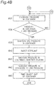
- step #31 before driving the sterilization system, in step #31, the object 2 to be sterilized is accommodated in the internal box 12 of the container 11.
- step #32 the air displacement pump 20 is energized to decrease the pressure in the container 11.
- step #33 a determination is made whether the pressure in the container 11 reaches the first pressure P101 which is equal to or higher than the triple point pressure of water.
- the pressure in the container 11 is measured by the pressure measuring unit 14, and the measurement is transmitted to the controller 23. Based on the output signal from the operator 24 of the controller 23, the displacement pump 20 and the solenoid valve 21 are controlled so that the pressure in the container 11 is decreased to the target pressure, i.e., the first pressure P101. If it is determined that the pressure in the container 11 reaches the first pressure P101, the solenoid valves 9, 18, and 21 connected to the container 11 are closed in step #34.
- the pressure measuring unit 14 continues to measure the pressure inside the container, and the time measurement unit 26 is activated to measure a period of time elapsed T102.
- a pressure difference between the first pressure P101 and the pressure measured after the elapse of the time T102 is obtained by the pressure increasing rate determining unit 30.
- the pressure difference and the period of time T102 are used to calculate an actual rate of pressure increase Rp114 by means of the calculator 32.
- the calculation result is temporarily stored in the memory 31.
- the memory 31 stores a reference rate of pressure increase Rp114a.
- a difference between the actual rate of pressure increase Rp114 and the reference rate of pressure increase Rp114a, both stored in the memory 31, is calculated and, based on the result, it is determined by the comparator 33 whether the actual rate of pressure increase Rp114 is equal to or less than the reference rate of pressure increase Rp114a.
- the reference rate of pressure increase Rp114a corresponds to the rate of pressure increase in the pressure increase operation from the first pressure P101 when no residual water exists. Accordingly, the existence of water on the object 2 can be determined by comparing the rates of increase Rp114 and Rp114a.
- step #36 If it is determined in step #36 that the actual rate of pressure increase Rp114 is equal to or less than the reference rate of pressure increase Rp114a, namely, no residual water exists on the object 2, the displacement pump 20 and the solenoid valve 21 are controlled to decrease the pressure in the container 11 in step #38. If it is determined in step #39 that the pressure in the container 11 is decreased to the third pressure P103 which is lower than the triple point pressure of water, the pressure in the container 11 is controlled at the third pressure for a certain period of time. After the elapse of the time T102, in step #40 the sterilant is injected into the container 11. After the further elapse of a certain period of time during which the container 11 is maintained in the same condition, plasma is generated in the container 11 in step #41. Then, in step #42 the pressure in the container 11 is increased to the second pressure P102. In the next step #43, the object 2 is removed from the container 11 and the sterilization process is terminated.
- step #36 If it is determined in step #36 that the actual rate of pressure increase Rp114 is greater than the reference rate of pressure increase Rp114a; namely, the residual water exists on the object 2, in step #44 the pressure in the container 11 is increased to the second pressure P102. Then, in the next step #45 the second pressure in the container 11 is maintained for a certain period of time. Then, steps #46 to #50 are repeated, which correspond to steps #32 to #36, respectively.
- step #50 If it is determined in step #50 that the actual rate of pressure increase Rp114 is equal to or less than the reference rate of pressure increase Rp114a; namely, no residual water exists on the object 2, in step #51, a determination is made in step #51 whether the number of times repeating the steps #46 to #50 is less than a predetermined value. If it is determined in step #51 that the number of repetitions is less than the predetermined value, the steps #37 to #43 are performed and then the sterilization process is terminated. If on the other hand it is determined in step #51 that the number of repetitions is greater than the predetermined value, an error message is indicated on the display (not shown) to turn off the system in step #52.
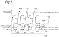
- step 101 For the first embodiment shown in Figs. 3A to 3C , a relation between the sterilization time elapsed and the pressure in which no residual water exists on the object 2 will be described with reference to a graph shown in Fig. 5 .
- the pressure in the container 11 is decreased by the displacement pump 20 during which the residual water existing outside or inside the object 2 is evaporated.
- the residual water loses its calories as it is evaporated. This process is hereinafter referred to as "step 101".
- the pressure is decreased to the first pressure P101 which is higher than the triple point pressure of water.
- the first pressure P101 is equal to or higher than the triple point pressure of water (610 Pa) at which water freezes into ice.
- the first pressure P101 is preferably in the range between 610 and 2,000 Pa, more preferably between 670 and 1,000 Pa.
- the first pressure P101 in the container 11 is maintained for the period of time T102. In this step, heat is transferred from the object to the cold residual water, warming and thereby evaporating the residual water.
- the first pressure P101 is higher than the triple point pressure of water, 610 Pa, which ensures that the residual water does not freeze during step 102.
- the first pressure P101 in the container 11 is maintained through the opening/closing control of the solenoid valve 21 connected to the air displacement pump 20, in response to a control signal from the controller 23 and using the pressure measured by the pressure measuring unit 14.
- the period of time T102 in step 102 may be equal to a period of time during which a half quantity of heat is transferred to the residual water.
- the period of time T102 is about 5 seconds.
- the certain period of time T102 is about 25 seconds.
- step 103 subsequent to step 102, the solenoid valve 18 is opened to allow the atmospheric air to inflow into the container 11 through the air filter 17.
- the pressure in the container 11 is increased to the second pressure P102 which is equal to the atmospheric pressure or quasi-atmospheric pressure which is close to the atmospheric pressure, thereby inflowing the atmospheric air having a higher temperature than that of the atmosphere in the container 11 into the container 11.
- the object 2 and the residual water are exposed to the atmospheric air, resulting in the increase of their temperatures.
- step 104 subsequent to step 103 the second pressure P102 is maintained in the container 11, and heat from the atmospheric air introduced in step 103 is transferred to the object 2 and the residual water.
- the period of time of step 104 may be determined as necessary.
- the object 2 and the residual water are heated in steps 103 and 104.
- the temperatures of the atmosphere in the container 11 and the object 2 in the container are higher than those at the end 112 of step 102, causing the decompression boiling of the residual water.
- steps 103, 104, 105 and 102 are repeated until it is determined at the end 11 of step 101 that no residual water exists in the container by the residual water determining section 25. If it is determined that no residual water exist at that point 111, the program proceeds to step 106 after the completion 112 of step 102 and then to step 107 in which the interior of the container 11 is maintained at the third pressure P103 which is equal to or less than the first pressure P101.
- the third pressure P103 is an appropriate pressure for injecting the sterilant into the container 11 and for the generation of plasma.
- the third pressure P103 is preferably in a range between 30 and 200 Pa.
- the third pressure P103 is equal to or less than the triple point pressure of water (610 Pa), at which water freezes into ice. Because the previous drying process has removed the residual water, no freezing would occur on the object 2.
- a high-frequency wave may be applied from the high-frequency generator 13 between the container 11 and the internal box 12 for the plasma generation.
- step 107 a predetermined quantity of the sterilant is injected via the solenoid valve 9 into the container 11 in the form of steam or vapor.
- step 109 the sterilant injected in the container 11 passes through the perforations of the internal box and subsequently adheres to the object 2 for its sterilization.
- a certain period of time necessary for the effective sterilization is allocated to step 109.
- step 109 the pressure in the container 11 is increased to the second pressure P102, terminating the first sterilization step. More preferably, step 109 is repeatedly performed, thereby ensuring the sterilization effect.
- the period of time T101 necessary for decreasing the pressure to the first pressure P101 which is equal to or higher than the triple point pressure of water is measured at the time measurement unit 26 through the monitoring the output of the pressure measuring unit 14 after starting the operation by the sterilization system.
- the period of time T101 spent for step 101 has a relationship with a quantity of the residual water existing on the object 2 in which the period of time T101 increases with the quantity of the residual water.
- Fig. 6 is a partial enlarged view of the graph in Fig. 5 showing an embodiment in which no residual water is detected by the determining section 25.
- the determining section determines that no residual water exists on the object 2 and the program proceeds from the end 112 in step 102 through steps 106 and 107 to step 108.
- the reference time T101a varies depending on the object 2 such as tweezers, scissors, forceps, endoscope, catheter, tray, hairdressing equipment, knives, cutting board and vaccine.
- Fig. 7 is a partial enlarged view of the graph in Fig. 5 showing an embodiment in which the residual water is detected by the determining section 25.
- the determining section 25 determines that the residual water exists on the object 2 and the program proceeds from the end 112 in step 102 through steps 103 and 104 to step 105.
- step 105 If it is determined that the actual time T105 for completing step 105 is greater than the reference time T101a in the memory 27, it is determined that there exists the residual water and then the program proceeds from the end 112 of step 102 through steps 103 and 104 to step 105 to repeat the drying process as shown in Fig. 7 . If, on the other hand, it is determined that T105 is equal to or less than T101a and then no residual water exists on the object 2, the program proceeds from the end 112 of step 102 through steps 106, 107, 108 and 109 to step 110 to terminate the sterilization step, as shown in Fig. 8 .
- step 104 If only a considerably small time or substantially no time is spent for step 104, the pressure in the container 11 at the beginning of step 105 may differ from the atmospheric pressure. In this instance, the actual time T105 in step 105 can vary. Therefore, at the beginning of step 105, a difference between the pressure in the container 11 measured by the pressure measuring unit 14 and the atmospheric pressure is calculated by the time calculating unit 28, which may be used for correcting the actual time T105 required for completing step 105 (see step #18 of Fig. 3C ).
- the number of repetition of the drying process may be limited.
- an error massage may be indicated on the display (not shown) of the sterilizer 1 and, if the drying process is repeated more than the predetermined number, the operation of the sterilizer 1 is terminated (see steps #20 and #21 of Fig. 3C ).
- the drying process is repeated as long as the residual water exists on the object 2, the pressure in the container 11 will never decrease less than the triple point pressure of water, which prevents the residual water on the object 2 from freezing.
- the sterilant injection begins only after the residual water is removed. Therefore, no problem occurs which would otherwise be caused by the freezing of the residual water.
- Fig. 9 is a graph showing a relationship between the pressure in the container and the time elapsed in the pressure reduction process obtained by an experiment in which an object, for example, a stainless tray was sterilized according to the sterilization process described as the first embodiment of the invention.
- the period of time T101 required for the pressure to reach the triple point pressure of water (610Pa) from the beginning the pressure decreasing operation increases in proportion to the quantity of the residual water on the tray.
- Fig. 10 is an enlarged graph showing a relationship between the pressure in the container and the time elapsed during which the pressure decreased near and to the triple point pressure of water 610 Pa in the experiment shown in Fig. 9 .
- T101 time elapsed during which the pressure decreased near and to the triple point pressure of water 610 Pa in the experiment shown in Fig. 9 .
- T101 time elapsed during which the pressure decreased near and to the triple point pressure of water 610 Pa in the experiment shown in Fig. 9 .
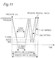
- FIG. 11 An experiment was made to examine an influence of pressure variation patterns to the quantity of residual water for an object made of an elongate hollow tube in the application of the sterilization process according to the first embodiment of the invention. The result is shown in Fig. 11 .
- Two pressure patterns with a single heating process were used.
- Used as the object was a fluororesin PTFE tube having an outer diameter of 2.0 millimeters, an inner diameter of 1.0 millimeters, and a length of 3,700 millimeters. One end of the tube was closed, and the tube was filled with about 2.9 milliliter water. The water filled tube was placed in the container 11. The water in the tube was observed through a window provided on the container 11.
- the first pressure pattern is that described in Patent Document 1 in which the pressure in the container 11 was decreased continuously to 50 Pa which is lower than the triple point pressure of water (610 Pa) in the first pressure decreasing process and the decreased pressure 50 Pa was maintained for three minutes. Then, the pressure was increased to the atmospheric pressure in the drying step. Immediately after the drying process, the pressure was decreased again to 50 Pa and then increased up to the atmospheric pressure in which a quantity of the residual water was measured.
- the water in the tube began to evaporate due to the decompression boiling after starting the pressure decrease from the atmospheric pressure. Then, when the pressure reached about 300 Pa and 200 Pa below the triple point pressure of water (610 Pa), water began to freeze into ice at the opening of the tube, which prevented the water from moving out of the tube. To melt the ice, plasma energy was supplied into the container for three minutes under the reduced pressure of 50 Pa, but the ice was not removed completely and the water still remained in the tube.
- the ice at the opening of the tube was melted by maintaining the pressure in the container at 50 Pa for three minutes and then introducing the atmospheric pressure into the container. This is because the heat of the heated container 11 was transferred through the incoming air to the tube and then to the residual water to melt the ice. In the process of pressure decrease to 50 Pa, a part of the residual water in the tube is removed out of the tube due to the decompression boiling; however, the water was still observed in the tube at 50 Pa. Immediately after the pressure decreased to 50 Pa, the atmospheric pressure was introduced in the container 1 and then the tube was taken out of the container in which an amount of water remaining in the tube was measured, which showed that 0.6 milliliters of water existed.
- the second pressure pattern is that described in the first embodiment of the invention, in which the pressure in the container 11 was decreased continuously to 1,100 Pa higher than the triple point pressure of water (610 Pa), the pressure 1,100 Pa was maintained for three minutes, the atmospheric pressure was introduced in the container, the pressure in the container is reduced again to 50 Pa, the atmospheric pressure was introduced in the container, and then an amount of residual water was measured.
- the water in the tube is evaporated after the pressure began to decrease from the atmospheric pressure due to the decompression boiling.
- the evaporation by the decompression boiling was maintained during which the pressure was maintained at 1,100 Pa less than the triple point pressure of water (610 Pa). This is because the heat of the tube was transferred for three minutes to the water cooled through the decompression boiling to maintain the boiling of the water.
- the water was observed in the tube after the elapse of three minutes in which the pressure in the container was maintained at 1,100 Pa, no water was frozen because the pressure in the container was maintained higher than the triple point pressure of water (610 Pa).
- the pressure in the container was maintained at 1,100 Pa for three minutes and then increased to the atmospheric pressure, during which heat of the heated container 11 was transferred through the atmospheric air inflowing into the container 11, increasing the temperature of the tube and the residual water thereon. Then, in the process of decreasing the pressure in the container 11 to 50 Pa, the residual water in the tube was partly evaporated from the tube due to the decompression boiling. When the pressure reached 50 Pa, there was a little residual water observed in the tube. Then, the pressure was increased to the atmospheric pressure, and the tube was taken out of the container 11 in which an amount of water remaining in the tube was measured, which showed that 0.2 milliliters of water existed.
- the second method or the second pressure pattern according to the first embodiment of the present invention generated less residual water than the first method or the first pressure pattern according to the process described in Patent Document 1.
- the possible cause is that in the first method the water frozen into ice at the opening of the tube to prevent the water in the tube from being evaporated effectively while in the second method the generation of the ice was effectively prevented and the water evaporation was accelerated.
- the second method may be suitable than the first method because the freezing of the residual water can be prevented throughout the operation. Also, a period of time required from the beginning to the end of the operation of the first method is 15 minutes and 50 seconds which is greater than that of the second method (i.e., 10 minutes and 30 seconds), and therefore the second method is more preferably in terms of execution time and energy consumption.
- the object 2 was a PTFE (fluororesin) tube having an outer diameter of 2.0 millimeters, an inner diameter of 1.0 millimeters, and a length of 2,000 millimeters. One end of the tube was closed, and the tube was filled with about 1.6 milliliter water. The water filled tube was placed in the container 11. The water in the tube was observed through a window provided on the container 11.
- PTFE fluororesin
- the pressure in the container 11 was decreased to 50 Pa lower than the triple point pressure of water (610 Pa).
- the pressure (50 Pa) was maintained for three minutes. Then the pressure was increased to the atmospheric pressure.
- the water began to evaporate immediately after the pressure decrease from the atmospheric pressure due to the decompression boiling. Then, the water began to freeze at the opening of the tube when the pressure decreased to about 300 to 200 Pa less than the triple point pressure of water (610 Pa), which prevented water from being evaporated from the tube.
- the pressure of 50 Pa was maintained for three minutes, plasma was generated to supply heat energy for melting the frozen ice; however, the frozen ice was maintained at the opening of the tube and thereby the residual water was retained within the tube.
- the ice was melted in the process for increasing the pressure in the container in order to measure the residual water.
- the tube was taken out of the container and then the residual water was measured, which showed that 0.4 milliliters of residual water existed on the tube.
- the pressure in the container 11 was decreased to 1,100 Pa higher than the triple point pressure of water (610 Pa) in the first pressure decreasing process and the pressure (1,100 Pa) was maintained for three minutes.
- the pressure was decreased again to 50 Pa and then increased to the atmospheric pressure.
- the water in the tube began to evaporate due to the decompression boiling.
- the evaporation of the water continued while the pressure is maintained at 1,100 Pa greater than the triple point pressure of water (610 Pa) because the water cooled due to the decompression boiling was heated for three minutes by the tube and thereby the decompression boiling was maintained due to the temperature increase of the water.
- the pressure of 1,100 Pa was maintained for three minutes and then decreased to 50 Pa. Immediately thereafter, the pressure was increased to the atmospheric pressure, and the tube was taken out from the container 11. Then, the measurement was made to determine the quantity of water remaining on the tube; however, no residual water was detected.
- the first method similar to that described in Patent Document 1 generated more residual water than that in the second method according to the first embodiment of the present invention. This is attributed to the fact that the ice blocks the opening of the tube to prevent the residual water from being vaporized effectively. Therefore, the second method capable of preventing the residual water from freezing throughout the operation is more preferably for vaporing the residual water and drying the tube.
- the first and second methods took substantially the same time, i.e., 8 minutes and 50 seconds for their operations.
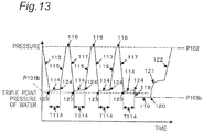
- Fig. 13 is a graph showing a relationship between period of time and pressure in the container during the sterilization process according to the second embodiment of the invention.
- the interior of the container 11 is decompressed by means of an exhausting pump 20 and thereby the residual water on the object 2 is evaporated and then exhausted.
- the residual water loses its temperature; namely, it is cooled.
- step 113 This step is hereinafter referred to as "step 113".
- the pressure in the container is decreased to the first pressure P101b which is equal to or higher than the triple point pressure at which water freezes (610 Pa).
- the first pressure P101b is preferably in a range between 610 Pa and 2,000 Pa, most preferably in a range between 670 Pa and 1,000 Pa.
- the solenoid valve 21 is closed. Then, the program proceeds to step 114 in which the pressure in the container 11 is increased from the first pressure P101b through the evaporation of the residual water.
- step 114 it is determined at the end 124 of step 114 that the rate of pressure increase Rp114 from the first pressure P101b is higher than the reference rate of pressure increase Rp114a, the program proceeds to step 115.
- the period of time T114 in step 114 is used to determining the rate of pressure increase Rp114.
- step 115 the solenoid valve 18 is opened to increase the pressure in the container 11 to the second pressure P102b which is equal to or close to the atmospheric pressure, causing the object 2 to be exposed to the heated atmospheric air, which results in the increase in temperature of the object 2 and the residual water thereon.
- step 116 the second pressure P102b is maintained. During the entire period of time of step 116, heat is transferred from the atmospheric air to the object 2 and the residual water thereon. The period of time can be determined depending on the types of the objects 2.
- step 115 and 116 are heated during steps 115 and 116 so that they have at step 117 higher temperatures than those at the end 124 of step 114, which causes the residual water to evaporate through the decompression boiling.
- the drying process as described above is repeated through steps 115, 116, 117 and 114 in this order, thereby accelerating the drying of the residual water.
- step 119 the pressure in the container 11 is decreased to the third pressure P103b which is lower than or approximately equal to the first pressure P101b.
- the third pressure P103b which is suitable for injecting the sterilant into the container 31 and for generating plasma, is preferably in a range between 30 Pa and 200 Pa.
- the third pressure P103b is lower than the triple point pressure at which water freezes (610 Pa). The drying process removes the residual water which might otherwise generate ice on the object 2.
- a high-frequency wave 13 from the high-frequency generator 13 may be applied between the container 11 and the internal box 12 to generate the plasma.
- a predetermined quantity of the sterilant is injected via the solenoid valve 9 into the container 11 in the form of steam or vapor.
- the injected sterilant passes the perforations of the internal box and subsequently adheres to the object 2.
- a certain time necessary for the effective sterilization is allocated to step 121.
- the pressure in the container 11 is increased to the second pressure P102b, which terminates the first sterilization step.
- step 109 is repeated to enhance the sterilization effect.
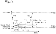
- Fig. 14 is an enlarged view of the graph of Fig. 13 for the operation in which no residual water is detected.
- the rate of pressure increase Rp114 is calculated by the pressure increasing rate determining unit 30, using a difference between the pressure P123 at the start 123 and the pressure at the end 124 of step 114 which are measured by the pressure measuring unit 14, and the period of time T114 spend in step 114.
- the memory 31 stores the reference rate of pressure increase Rp114a in which no residual water is detected.
- the rate of pressure increase in the container 11 correlates with the quantity of the residual water on the object 2 so that a vapor pressure as well as the rate of pressure increases as the quantity of the residual water.
- the measured rate of pressure increase Rp114 is compared with the reference rate of pressure increase Rp114a and it is determined that Rp114 is equal to or less than Rp114a, it is determined that no residual water exists on the object 2 by the determining section 25. Then, the program proceeds from the end 124 of step 114 through steps 118, 119 and 121 to step 122 in this order.
- the reference rate of pressure increase Rp114a varies depending on the types of the objects 2 such as tweezers, scissors, forceps, endoscope, catheter, tray, hairdressing equipment, knives, cutting board and vaccine.
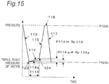
- Fig. 15 is an enlarged view showing a part of the graph Fig. 13 which illustrates an operation performed when it is determined that the residual water exists on the object.
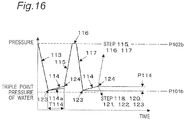
- Fig. 16 is a graph showing a process subsequent to that shown in Fig. 15 in which it is determined whether the residual water exists on the object. If it is determined by the comparator 33 that the actual rate of pressure increase Rp114 is greater than the reference rate of pressure increase Rp114a and, as a result, it is determined by the determining section 25 that the residual water exists on the object, as shown in Fig. 5 the program proceeds from the end 124 of step 114 to the drying process performed in steps 115, 116, 117 and 114.
- the program proceeds from the end 124 of step 114 through steps 118, 119 and 121 to step 122 to terminate the sterilization step.
- the number of repetition of the drying process may be limited.
- an error message may be indicated on the display (not shown) of the sterilizer 1 if the drying process is repeated more than a predetermined number and also the sterilizer 1 is deactivated in steps #51 and #52 of Fig. 4C .
- the drying process is repeated.
- the pressure in the container 11 is maintained less than the triple point pressure of water, which prevents the residual water on the object 2 from freezing.
- the sterilant is injected only after the removal of the residual water and therefore no freezing occurs on the object.
- the experiment was made by disposing a plastic tray or bowl in the container 11, placing a certain amount of water on the tray, opening a solenoid valve 21 to decrease the pressure in the container to 1,000 Pa (which is higher than the triple point pressure of water 610 Pa), and then closing the solenoid valve 21.
- a relationship was experimentally determined between a period of time elapsed after the pressure in the container 11 reached 1,000 Pa and the pressure in the container 11. The experiment was performed for five different quantities of residual water ranging between 0 and 50 milliliter.
- Fig. 18 is a graph showing a variation of the pressure together with a point of freezing and points of measuring the concentration of the residual hydrogen peroxide.
- the quantities of the residual sterilant on the object 2 were measured in the first and second patterns and the measurements were compared.
- the first pattern the sterilant was injected in the container in which the frozen water existed on the object.
- the second pattern the sterilant was injected in the container in which no water existed on the object.
- the sterilant was injected into the container in which the residual water frozen.
- the first pattern included disposing a stainless tray with 50 gram water received thereon in the container 11, and decreasing the pressure in the container 11.
- the pressure decreasing process the water frozen into ice when the pressure decreased to 250 Pa (less than the triple point pressure of water 610 Pa).
- the pressure decreasing continued for 25 minutes at which the pressure in the container reached 110 Pa.
- 2.2 milliliter sterilant containing 60 percent hydrogen peroxide was injected into the container 11. After eight minutes elapsed, the pressure in the container increased due to the evaporation of the hydrogen peroxide to 590 Pa. Then, the pressure was increased to the atmospheric pressure.
- the tray was taken out of the container 11 and was washed after melting the ice on the tray into a solution of hydrogen peroxide.
- the concentration and the weight of the hydrogen peroxide were measured to determine the quantity of the residual hydrogen peroxide on the tray.
- the measured quantity of residual hydrogen peroxide per unit area on the tray was 1.2 mg/cm 2 .
- the sterilant was injected in the container in which no the residual water or ice existed. Specifically, a dried stainless-steel tray was placed in the container 11 and the pressure in the container was decreased. Then, the pressure in the container 11 was maintained in a range between 110 Pa to 120 Pa. After 25 minutes elapsed from the start of the pressure decreasing process, 2.2 milliliter sterilant containing 60 percent hydrogen peroxide was injected into the container 11. After eight minutes elapsed, the pressure in the container increased to 1,250 Pa due to the evaporation of the hydrogen peroxide. Then, the pressure in the container was increased to the atmospheric pressure.
- the tray was taken out of the container 11 and an appropriate amount of water was put on the tray to wash tray and to generate a solution of hydrogen peroxide. Using the weight of the solution and the concentration of hydrogen peroxide in the solution, the quantity of the residual hydrogen peroxide on the tray was measured. The measured quantity of hydrogen peroxide per unit area was 0.0053 mg/cm 2 .
- water of 10g was placed on a stainless-steel tray which was disposed in the container 11.
- the pressure in the container 11 was decreased to 700 Pa to 800 Pa which was higher than the triple point pressure of water 610 Pa. Then, (a) the decreased pressure was maintained for a minute, (b) the pressure was increased to the atmospheric pressure which was maintained for five minutes, and (c) the pressure was decreased again. These steps (a) to (c) were repeated eight times. After confirmed the fact that no water existed on the tray, the pressure was decreased to 60 Pa which was maintained for 12 minutes. 2.2 milliliter sterilant containing 60 percent hydrogen peroxide was injected into the container 11. After eight minutes elapsed, the pressure in the container increased to 2,300 Pa due to the evaporation of the hydrogen peroxide. Then, the pressure in the container 11 was increased to the atmospheric pressure.
- the tray was taken out of the container 11 and an appropriate amount of water was placed on the tray which tray was then washed to generate a solution of hydrogen peroxide. Using the weight of the solution and the concentration of hydrogen peroxide in the solution, the quantity of the residual hydrogen peroxide on the tray was measured. The measured quantity of hydrogen peroxide per unit area was 0.0019 mg/cm 2 .
- the sterilization method according to the invention prevents the residual water from freezing into ice on the object or in the vicinity thereof in the sterilization process in which the container is decompressed and then the object is sterilized. That is that the condensation of the sterilant and the defective sterilization are overcome by the drying process which is conducted under the pressure more than the triple point pressure of water and by the sterilizing process which is conducted after confirming that the interior of the container is fully dried.
- the sterilization method and the sterilizer according to the present invention are applicable to various types of sterilizers such as a gas plasma sterilizer, a sterilizer using hydrogen peroxide, a sterilizer using peracetic acid vapor, in which a method including a step of decreasing the pressure less than the triple point pressure of water.
- the object 2 may include various things such as cut vegetables, herbs, leaves of tobacco, plant seeds, eggs, rice, tea, or mushrooms. Further, they are applicable to various purposes such as keeping freshness, preventing flavor deterioration, drying foods, removing odor from shoes, and sterilizing the soil.
- the present invention is effectively used in a method for sterilizing an object to be sterilized in a decompressed container using a sterilant and a sterilizer.
Landscapes
- Life Sciences & Earth Sciences (AREA)
- Engineering & Computer Science (AREA)
- Chemical & Material Sciences (AREA)
- Wood Science & Technology (AREA)
- Zoology (AREA)
- Food Science & Technology (AREA)
- Polymers & Plastics (AREA)
- Health & Medical Sciences (AREA)
- General Chemical & Material Sciences (AREA)
- Chemical Kinetics & Catalysis (AREA)
- Epidemiology (AREA)
- Animal Behavior & Ethology (AREA)
- General Health & Medical Sciences (AREA)
- Public Health (AREA)
- Veterinary Medicine (AREA)
- Apparatus For Disinfection Or Sterilisation (AREA)
Applications Claiming Priority (3)
| Application Number | Priority Date | Filing Date | Title |
|---|---|---|---|
| JP2012215307 | 2012-09-27 | ||
| PCT/JP2013/075498 WO2014050744A1 (fr) | 2012-09-27 | 2013-09-20 | Procédé et dispositif de stérilisation |
| EP13840965.1A EP2902042A4 (fr) | 2012-09-27 | 2013-09-20 | Procédé et dispositif de stérilisation |
Related Parent Applications (1)
| Application Number | Title | Priority Date | Filing Date |
|---|---|---|---|
| EP13840965.1A Division EP2902042A4 (fr) | 2012-09-27 | 2013-09-20 | Procédé et dispositif de stérilisation |
Publications (1)
| Publication Number | Publication Date |
|---|---|
| EP3437664A1 true EP3437664A1 (fr) | 2019-02-06 |
Family
ID=50388148
Family Applications (2)
| Application Number | Title | Priority Date | Filing Date |
|---|---|---|---|
| EP18194063.6A Withdrawn EP3437664A1 (fr) | 2012-09-27 | 2013-09-20 | Procédé de stérilisation |
| EP13840965.1A Withdrawn EP2902042A4 (fr) | 2012-09-27 | 2013-09-20 | Procédé et dispositif de stérilisation |
Family Applications After (1)
| Application Number | Title | Priority Date | Filing Date |
|---|---|---|---|
| EP13840965.1A Withdrawn EP2902042A4 (fr) | 2012-09-27 | 2013-09-20 | Procédé et dispositif de stérilisation |
Country Status (6)
| Country | Link |
|---|---|
| US (1) | US10058106B2 (fr) |
| EP (2) | EP3437664A1 (fr) |
| JP (1) | JP6139542B2 (fr) |
| CN (1) | CN104661687B (fr) |
| RU (1) | RU2670972C9 (fr) |
| WO (1) | WO2014050744A1 (fr) |
Families Citing this family (14)
| Publication number | Priority date | Publication date | Assignee | Title |
|---|---|---|---|---|
| ES2875881T3 (es) * | 2013-09-06 | 2021-11-11 | Tso3 Inc | Métodos y aparatos de esterilización y control adaptativo de los mismos |
| US10709803B2 (en) | 2013-09-06 | 2020-07-14 | Ts03 Inc. | Sterilization apparatus and adaptive control thereof |
| JP6408904B2 (ja) * | 2014-12-25 | 2018-10-17 | 東京エレクトロン株式会社 | 真空引き方法及び真空処理装置 |
| JP6631031B2 (ja) * | 2015-04-24 | 2020-01-15 | キヤノンマーケティングジャパン株式会社 | 滅菌方法 |
| US10441672B2 (en) * | 2016-04-26 | 2019-10-15 | Asp Global Manufacturing Gmbh | Apparatus and method for detecting moisture in a vacuum chamber |
| US9931427B2 (en) | 2016-05-11 | 2018-04-03 | Ethicon, Inc. | Apparatus and method for detecting moisture in a vacuum chamber |
| US10350319B2 (en) * | 2017-01-23 | 2019-07-16 | Sterilucent, Inc. | Method for liquid detection and drying |
| US10458705B2 (en) | 2017-02-02 | 2019-10-29 | Asp Global Manufacturing Gmbh | Apparatus and method for detecting moisture in a vacuum chamber |
| FI3600456T3 (fi) | 2017-03-27 | 2023-10-26 | Regeneron Pharma | Sterilointimenetelmä |
| AU2019389294B2 (en) * | 2018-11-29 | 2025-01-09 | Ethicon, Inc. | Operating room coating applicator and method |
| FR3093404B1 (fr) * | 2019-03-08 | 2023-04-14 | Jean Marc Tachet Creation | Procédé d’enrichissement d’aliments en protéines et/ou en compléments alimentaires |
| WO2020201932A1 (fr) | 2019-03-29 | 2020-10-08 | Advanced Sterilization Products, Inc. | Procédé de détermination de volume de charge pour un appareil de stérilisation |
| EP3886946A1 (fr) | 2019-06-05 | 2021-10-06 | Regeneron Pharmaceuticals, Inc. | Dispositifs et procédés pour l'administration précise de doses |
| USD1120314S1 (en) | 2022-11-30 | 2026-03-24 | Regeneron Pharmaceuticals, Inc. | Dose delivery device |
Citations (2)
| Publication number | Priority date | Publication date | Assignee | Title |
|---|---|---|---|---|
| JP4526649B2 (ja) | 1999-03-31 | 2010-08-18 | エシコン・インコーポレイテッド | 滅菌処理方法 |
| US20100316527A1 (en) * | 2009-06-11 | 2010-12-16 | Sterilucent, Inc. | Apparatus and method for drying and then sterilizing objects in a load using a chemical sterilant |
Family Cites Families (7)
| Publication number | Priority date | Publication date | Assignee | Title |
|---|---|---|---|---|
| US5317896A (en) | 1992-03-13 | 1994-06-07 | American Sterilizer Company | Method of detecting liquid in a sterilization system |
| US5656238A (en) * | 1994-10-11 | 1997-08-12 | Johnson & Johnson Medical, Inc. | Plasma-enhanced vacuum drying |
| US5961922A (en) * | 1996-10-04 | 1999-10-05 | Johnson & Johnson Medical, Inc. | Method and apparatus for detecting water entrapment in a vaccum chamber |
| CA2443046C (fr) * | 2003-09-26 | 2011-10-11 | Tso3 Inc. | Methode de sterilisation a l'ozone amelioree |
| BRPI0400237A (pt) * | 2004-01-16 | 2005-08-16 | Tadashi Shiosawa | Processo de esterelização a vácuo com aplicação de vapor de uma mistura de ácido peracético com peróxido de hidrogênio e plasma de gás residual de ar atmosférico excitado por descarga elétrica dc pulsada; dispositivos e métodos operacionais utilizados no processo de esterilização |
| JP3859691B2 (ja) | 2004-03-31 | 2006-12-20 | 株式会社湯山製作所 | 滅菌方法及び装置 |
| US8230616B2 (en) * | 2009-06-11 | 2012-07-31 | Sterilucent, Inc. | Apparatus and method for drying and sterilizing objects in a load |
-
2013
- 2013-09-20 CN CN201380050042.XA patent/CN104661687B/zh active Active
- 2013-09-20 EP EP18194063.6A patent/EP3437664A1/fr not_active Withdrawn
- 2013-09-20 WO PCT/JP2013/075498 patent/WO2014050744A1/fr not_active Ceased
- 2013-09-20 RU RU2015107047A patent/RU2670972C9/ru not_active Application Discontinuation
- 2013-09-20 EP EP13840965.1A patent/EP2902042A4/fr not_active Withdrawn
- 2013-09-20 JP JP2014538468A patent/JP6139542B2/ja active Active
- 2013-09-20 US US14/431,127 patent/US10058106B2/en active Active
Patent Citations (2)
| Publication number | Priority date | Publication date | Assignee | Title |
|---|---|---|---|---|
| JP4526649B2 (ja) | 1999-03-31 | 2010-08-18 | エシコン・インコーポレイテッド | 滅菌処理方法 |
| US20100316527A1 (en) * | 2009-06-11 | 2010-12-16 | Sterilucent, Inc. | Apparatus and method for drying and then sterilizing objects in a load using a chemical sterilant |
Non-Patent Citations (1)
| Title |
|---|
| RIKA YOSHIDA ET AL.: "Hydrogen Peroxide Vapour in the Proximity of Hydrogen Peroxide Sterilisers", JPN J ENVIRONMENT INFECT, vol. 26, no. 4, 2011, pages 239 - 242 |
Also Published As
| Publication number | Publication date |
|---|---|
| US10058106B2 (en) | 2018-08-28 |
| EP2902042A1 (fr) | 2015-08-05 |
| US20150313250A1 (en) | 2015-11-05 |
| RU2670972C2 (ru) | 2018-10-26 |
| RU2670972C9 (ru) | 2018-11-22 |
| EP2902042A4 (fr) | 2016-09-21 |
| JPWO2014050744A1 (ja) | 2016-08-22 |
| RU2015107047A (ru) | 2016-11-20 |
| CN104661687B (zh) | 2018-01-09 |
| WO2014050744A1 (fr) | 2014-04-03 |
| JP6139542B2 (ja) | 2017-05-31 |
| CN104661687A (zh) | 2015-05-27 |
Similar Documents
| Publication | Publication Date | Title |
|---|---|---|
| US10058106B2 (en) | Sterilization method and sterilizer | |
| EP1146915B1 (fr) | Methode de sterilisation d'un article garantissant l'asepsie dudit article | |
| JP4689090B2 (ja) | 滅菌に対する負荷の適合性を判定する方法 | |
| US9522205B2 (en) | Multi mode low temperature plasma sterilizer | |
| JP2004130080A (ja) | 温度調整型拡散通路による滅菌方法 | |
| JP4421181B2 (ja) | 滅菌剤を濃縮し、濃縮した滅菌剤で物品を滅菌する装置及び方法 | |
| JP7214348B2 (ja) | 医療器具の乾燥方法 | |
| US20200038534A1 (en) | Apparatus and method for detecting moisture in a vacuum chamber | |
| CN107432943A (zh) | 用于检测真空室中水分的设备和方法 | |
| JP2004130081A (ja) | 容器の中の流れによる滅菌方法 | |
| EP3570898B1 (fr) | Procédé de détection et de séchage de liquide | |
| JP4330940B2 (ja) | 制限装置を伴う滅菌装置 |
Legal Events
| Date | Code | Title | Description |
|---|---|---|---|
| PUAI | Public reference made under article 153(3) epc to a published international application that has entered the european phase |
Free format text: ORIGINAL CODE: 0009012 |
|
| STAA | Information on the status of an ep patent application or granted ep patent |
Free format text: STATUS: THE APPLICATION HAS BEEN PUBLISHED |
|
| AC | Divisional application: reference to earlier application |
Ref document number: 2902042 Country of ref document: EP Kind code of ref document: P |
|
| AK | Designated contracting states |
Kind code of ref document: A1 Designated state(s): AL AT BE BG CH CY CZ DE DK EE ES FI FR GB GR HR HU IE IS IT LI LT LU LV MC MK MT NL NO PL PT RO RS SE SI SK SM TR |
|
| STAA | Information on the status of an ep patent application or granted ep patent |
Free format text: STATUS: REQUEST FOR EXAMINATION WAS MADE |
|
| 17P | Request for examination filed |
Effective date: 20190802 |
|
| RBV | Designated contracting states (corrected) |
Designated state(s): AL AT BE BG CH CY CZ DE DK EE ES FI FR GB GR HR HU IE IS IT LI LT LU LV MC MK MT NL NO PL PT RO RS SE SI SK SM TR |
|
| STAA | Information on the status of an ep patent application or granted ep patent |
Free format text: STATUS: EXAMINATION IS IN PROGRESS |
|
| 17Q | First examination report despatched |
Effective date: 20201223 |
|
| STAA | Information on the status of an ep patent application or granted ep patent |
Free format text: STATUS: THE APPLICATION IS DEEMED TO BE WITHDRAWN |
|
| 18D | Application deemed to be withdrawn |
Effective date: 20250617 |