EP3437758A1 - Dispositif de mesure permettant la mesure d'une fente de coulée d'une installation de coulée continue et utilisation dudit dispositif de mesure permettant la mesure d'une fente de coulée - Google Patents
Dispositif de mesure permettant la mesure d'une fente de coulée d'une installation de coulée continue et utilisation dudit dispositif de mesure permettant la mesure d'une fente de coulée Download PDFInfo
- Publication number
- EP3437758A1 EP3437758A1 EP17184150.5A EP17184150A EP3437758A1 EP 3437758 A1 EP3437758 A1 EP 3437758A1 EP 17184150 A EP17184150 A EP 17184150A EP 3437758 A1 EP3437758 A1 EP 3437758A1
- Authority
- EP
- European Patent Office
- Prior art keywords
- measuring device
- measuring
- rotation
- arms
- segment
- Prior art date
- Legal status (The legal status is an assumption and is not a legal conclusion. Google has not performed a legal analysis and makes no representation as to the accuracy of the status listed.)
- Withdrawn
Links
Images



Classifications
-
- B—PERFORMING OPERATIONS; TRANSPORTING
- B22—CASTING; POWDER METALLURGY
- B22D—CASTING OF METALS; CASTING OF OTHER SUBSTANCES BY THE SAME PROCESSES OR DEVICES
- B22D11/00—Continuous casting of metals, i.e. casting in indefinite lengths
- B22D11/16—Controlling or regulating processes or operations
- B22D11/20—Controlling or regulating processes or operations for removing cast stock
- B22D11/208—Controlling or regulating processes or operations for removing cast stock for aligning the guide rolls
-
- B—PERFORMING OPERATIONS; TRANSPORTING
- B21—MECHANICAL METAL-WORKING WITHOUT ESSENTIALLY REMOVING MATERIAL; PUNCHING METAL
- B21B—ROLLING OF METAL
- B21B38/00—Methods or devices for measuring, detecting or monitoring specially adapted for metal-rolling mills, e.g. position detection, inspection of the product
- B21B38/10—Methods or devices for measuring, detecting or monitoring specially adapted for metal-rolling mills, e.g. position detection, inspection of the product for measuring roll-gap, e.g. pass indicators
-
- B—PERFORMING OPERATIONS; TRANSPORTING
- B22—CASTING; POWDER METALLURGY
- B22D—CASTING OF METALS; CASTING OF OTHER SUBSTANCES BY THE SAME PROCESSES OR DEVICES
- B22D11/00—Continuous casting of metals, i.e. casting in indefinite lengths
- B22D11/16—Controlling or regulating processes or operations
-
- G—PHYSICS
- G01—MEASURING; TESTING
- G01B—MEASURING LENGTH, THICKNESS OR SIMILAR LINEAR DIMENSIONS; MEASURING ANGLES; MEASURING AREAS; MEASURING IRREGULARITIES OF SURFACES OR CONTOURS
- G01B5/00—Measuring arrangements characterised by the use of mechanical techniques
- G01B5/14—Measuring arrangements characterised by the use of mechanical techniques for measuring distance or clearance between spaced objects or spaced apertures
Definitions
- the invention relates to a measuring device for measuring a casting gap in a continuous casting plant and to a use of this measuring device for measuring a casting gap.
- a continuous casting plant - for casting steel slabs - comprises - in a passage direction of the strand through the continuous casting - including a pan with an outlet pipe, arranged below the pan distribution basin with a pouring tube and arranged in the distribution basin plugs and one below the Verteilerbeckens arranged and a lower end of the pouring tube receiving and cooled wide side plates and cooled narrow side plates having mold.
- liquid steel which is introduced via the outlet pipe in the distribution basin. From the distribution basin in turn, the liquid steel is introduced via the pouring tube into the mold, wherein a mass flow of the steel flowing into the mold is controlled by means of the plug.
- the steel cools (primarily) at its contact surfaces with the (cooled) broad side plates and the (cooled) narrow side plates of the mold and solidifies in this case, so that the steel emerges from the mold in the form of a strand having a rectangular cross section.
- the strand Upon emergence, the strand has a solidified shell of - usually - a few centimeters thick, while much of its cross-section is still liquid.
- the strand is by means of a strand guiding system by a below or below the mold arranged so-called casting arc - from a vertical to a horizontal - and then output of the pouring bow horizontally further - led or by strand guide system support elements, d. H. Rolls of the strand guiding system, supported and guided or transported away.
- the roles of the strand guiding system which are usually installed in segments (roller track segments) or directly in the casting, come - usually in pairs and so forming a casting gap or roller gap - on opposite sides of the strand (vividly seen on an upper side and on a lower side the strand) - this supporting and guiding - to the plant, in addition to a degree of bulging of the strand, which occurs bulging due to acting on a strand shell ferrostatic pressure to reduce.
- the strand is cooled by air / water spraying (secondary).
- a follower unit such. B. a flame cutting machine, by means of which the strand - in the form of slabs - is cut or cut.
- the strand can also be further processed directly by a (different) follower unit, for example a rolling stand of a cast-rolled composite plant, without first being cut into pieces.
- a (different) follower unit for example a rolling stand of a cast-rolled composite plant, without first being cut into pieces.
- the strand guide rollers of the strand guiding system by means of which the strand - supported - is transported away and are exposed to the highest stresses, belong because of their u. a. shaping / maintaining influence on the strand and its strand surface - and thus on the quality of the strand or the slab - to central components of a continuous casting plant.
- monitoring of the casting or roll gap d. H. the monitoring of the distance of the two "pairwise belonging", on the opposite sides of the strand or at the top and at the bottom of the strand coming to rest (and so the casting gap forming), the strand leading support elements / rollers of the strand guiding system, in Specifically, a measurement and / or adjustment of a (given value) specifiable casting or roll gap, for the quality of the slab of outstanding importance.
- An object of the invention is to provide a measuring device for measuring a casting or roll gap in a continuous casting, which is inexpensive and by means of which the G fauxspaltshift can be performed efficiently and with high accuracy.
- This object is achieved by a measuring device for measuring a casting or roll gap (hereinafter usually only casting or roll gap) in a continuous casting plant and by using this measuring device for measuring a casting or roll gap with the features of the respective independent claim ,
- the measuring device for measuring a casting gap in a continuous casting plant has two arms which are rotatable about a common axis of rotation, i. H. a first arm and a second arm, and a Drehwinkelaufillon for measuring a relative (rotation) angle of the two arms to each other.
- such a Drehwinkelaufrich an analog Wheelwinkelaufsacrificing or rotary / swivel angle sensor in particular an analog inductive Drehwinkelaufsacrificing or rotary / swivel angle sensor, be, which in particular by its compact design, its high (measurement) accuracy and its excellent "price For money.
- the inductive rotary / swivel angle sensor RIPS series P505 the company ALTHEN GmbH measuring and sensor technology.
- the RIPS P505 turn / tilt sensor itself contains all the electronics, including the necessary EMC components.
- the rotary encoder is installed in a metal housing, tight to IP67. Flange and servo mount are made of aluminum.
- Each of the two arms has at least one segment, in simple terms a (spatial) portion, whose respective segment outer surface is a portion of a surface of a common sphere.
- segment outer surfaces also referred to as spherical shells
- spherical shells have a matching, ie the same, three-dimensional (space) curvature or sphere of a (specific or common) sphere.
- the (segment) outer surface of an arm segment can be understood as that surface of the respective arm segment which faces away from the respective other arm segment.
- the arm segments but also the other components of the measuring device may be made of a steel material, they are characterized highly wear resistant.
- the segment outer surfaces may be further treated, for example, ground and / or hardened, so as to be even more wear-resistant and / or smoother.
- the device When using the measuring device for measuring a casting gap in a continuous casting plant, the device can then be introduced into a casting / roll gap formed by two associated support elements / rolls such that one of the two outer segments contacts one of the two associated support elements / rolls.
- the relative (locking) angle of rotation of the two arms relative to one another can then be measured using the rotary angle sensor.
- the relative (rotation) angle can then be converted into a linear distance measure, i. H. the height of the G convince- / Rollenspalts, be converted.
- the measurement of the casting / roll gap between the (belonging together, the casting gap forming) roles can be done both in a workshop and in the continuous casting.
- the measured value for the casting / roller gap can then be used as the calibration value for a position-controlled roller table segment.
- the invention is based on the consideration and knowledge that systematic (measurement) errors can occur with each measurement, for example by incorrectly adjusted, as tilted or twisted (in the casting gap) introduced or used, measuring devices (systematic geometric measurement error).
- segment outer surfaces as a surface portion of a common ball (“ball segment / ball shell"), it is possible to eliminate such a systematic or systematic geometric measurement error, for example, wrong, such as tilted, adjustment (the measuring device in the casting gap) or to eliminate or minimize as much as possible.
- the measuring device according to the invention is - as far as possible - “immune” to systematic geometric measurement errors.
- the measuring device according to the invention is - as far as possible - immune to systematic geometrical measurement errors, such as may arise in the case of a tilted position of the measuring device in the casting gap
- the measuring device according to the invention enables, in particular, a restricted casting gap (due to geometrical conditions and / or environmental conditions) or roller gap, for example, in the "inside" of a roller conveyor segment, can be measured efficiently and with high accuracy, the measuring device according to the invention - because of their "immunity error" - just not completely exactly inserted or positioned in the casting gap.
- a casting gap measurement (in particular under "difficult conditions") can be carried out efficiently and with high accuracy, whereby high-quality slabs can then be produced in a continuous casting plant.
- the safety - in the manual measurement of a particular hard to reach casting gap by an operator - can be increased by the measuring device according to the invention, simplifies the "error immunity" of the measuring device according to the invention the manual insertion of the measuring device in the casting gap to be measured.
- a measuring device is cost-effective, in particular because of its easily manufactured (individual) components, whereby standard components can also be used here. In addition, it is very compact.
- the measuring device provides a new measuring device with which it is possible to efficiently and with, in particular in a roller conveyor segment with individually adjustable roles, especially accessible with difficulty or especially under "difficult conditions", casting / roller gap high accuracy to measure.
- the diameter of the common ball is selected from a range of 150 mm to 350 mm, in particular from a range of 200 mm to 300 mm, particularly preferably from a range of 220 mm to 250 mm.
- the spherical radius defining the sphere in the case of the arm segments or "spherical segments / spherical shells" can be from a range of 75 mm to 175 mm, in particular from a range of 100 mm to 150 mm, particularly preferably from a range of 110 mm to 125 mm, be selected.
- the diameter in the measuring device can be adapted to a desired casting / roll gap.
- the diameter of the sphere in the measuring device may also be 230 mm.
- spherical coordinates r (spherical radius), ⁇ (azimuth angle), ⁇ (polar angle)
- [0 ° ⁇ ⁇ ⁇ about 90 ° ] or [0 ° ⁇ ⁇ ⁇ about 80 °] or [0 ° ⁇ ⁇ ⁇ about 70 °] or [0 ° ⁇ ⁇ ⁇ about 60 °] is writable.
- Such designed or measured segment outer surfaces represent a good compromise between a large contact area (of segment outer surface and roller surface) and thus a large "tilt tolerance range" or a plurality of measurement positions and a small size of the measuring device.
- the two arms rotatable about a common axis of rotation using a spring are braced against each other.
- a spring or spiral spring may be so “functionally” mounted between the arms that their tension “pushing apart” of the arms, ie an increase in an opening angle between the arms, causes.
- the two arms rotatable about a common axis of rotation using a rolling bearing, in particular a ball bearing, are rotatably supported against each other. If standard bearings are used here, this can have a cost-effective effect on the measuring device.
- the two arms rotatable about a common axis of rotation one, in particular using at least one, in particular mechanical, stop limitable, maximum mechanical (Ver) rotation angle range of about +/- 12.5 ° or from about +/- 10 ° or from about +/- 7.5 ° or from about +/- 5 °.
- the two arms which are rotatable about a common axis of rotation can measure, in particular using the rotational angle sensor, the maximum metrological (rotation) range of about +/- 12.5 ° or about +/- 10 ° or from approx. +/- 7.5 ° or approx. +/- 5 ° or approx. +/- 5 °.
- the maximum mechanical (ver) rotation angle range and / or the maximum metrological (ver) rotation angle range can, as well as the ball diameter also, to the target value of the G dirt- / Rollenspalts to be measured be adjusted.
- the arms of the measuring device can be 20 mm above the target value of the target G fauxspalts out or can close up to 55mm below the setpoint (to possibly a mechanical end stop becomes effective).
- the measuring device would thus have a maximum mechanical clearance of 185 mm to 250 mm.
- an angular position of the arms in an opening range of 220 mm-240 mm can be detected metrologically by means of the above-exemplified measuring device (ball diameter and target-cast-roll gap 230 mm), which with the selected geometry at the rotational angle sensor a measuring range of ⁇ 7, 5 ° corresponds.
- the maximum mechanical (locking) rotational angle range is greater than the maximum metrological (locking) rotational angle range.
- the arms of the measuring device can open beyond a target value of the casting gap to be measured or can close below the setpoint (to possibly a mechanical end stop is effective), without that this would be detected by each Wheelwinkelaufillon.
- Sollg cashspalt 230 mm the dummy bar itself typically a mechanical height of 200 mm (for weight and cost reasons, the dummy bar is built as easy as necessary and therefore has a lower height than the roller gap itself) and is moved by the driver rollers in the roller table.
- the Drehwinkelaufsacrificing is an analog Wheelwinkelaufmix, in particular an inductive analog Wheelwinkelaufmix is.
- a necessary A / D conversion of an analog signal of such an analog rotary encoder can also be done with commercially available and therefore inexpensive industrial standard electronic components and is no real disadvantage compared to digital angle encoders.
- the analog signal of such an analog rotary encoder (cf the above example of a measuring device) at a maximum measuring or angular range of ⁇ 7.5 ° - corresponding to a mechanical movement of the measuring device of ⁇ 10 mm - can be converted to 13 bits, which is an angular resolution of approximately 7 seconds of arc or a spatial resolution of the casting gap to be measured of about 25 microns corresponds, which in turn corresponds to half of - for example - required measurement accuracy with respect to the casting gap of 50 microns.
- each of the two arms has at least one first further extension segment, in particular a first further and a second further extension segment, which first and / or second extension segment is connected to the respective segment, in particular in one piece.
- Such extension segments in the measuring device can facilitate the positioning of the measuring device (in the casting / roll gap).
- first and / or the second extension segment has a respective extension segment outer surface, which is a portion of a surface of a right circular cylinder, in particular a straight circular cylinder having the diameter of the common ball.
- each arm has a base support on which the respective segment and / or the first further extension segment and / or the second further extension segment is releasably, in particular using a screw, arranged / are.
- the Drehwinkelaufsacrificing in the region of the common axis of rotation of the two rotatable about the common axis of rotation arms, in particular at least partially in a longitudinal bore in a shaft through which passes the common axis of rotation is arranged.
- the Drehwinkelaufillon can be arranged in the "interior" of the common axis of rotation of the arms of the measuring device.
- the Drehwinkelaufsacrificing can be protected from external environmental influences, such as mechanical shocks, moisture and / or dust; Also, such an arrangement can contribute to a compact design of the measuring device.
- the two arms rotatable about the common axis of rotation are configured such that when the two arms rotatable about the common axis of rotation are rotated relative to each other, the two segment outer surfaces on the surface of the common sphere are to be rotated lie ("initial position” with "initial height"), then a center of the common sphere spaced, in particular at a distance of about 60 mm or about 55mm or about 50 mm or about 45 mm, from the common Rotary axis is located ("center offset").
- the measuring device is arranged on a longitudinal rail, movable in a longitudinal direction of the longitudinal rail, in particular motorized or movable by hand.
- a power supply in particular a power supply, of an engine, can take place via supply lines or batteries.
- a data acquisition of measurement data of the measuring device and / or a control of the motor (evaluation unit) can be mounted directly on the rail or housed in a separate evaluation box.
- a Human Machine Interface can be used to control a measurement process and for a measurement, evaluation and visualization.
- Data between the HMI and the evaluation unit can be transmitted by cable or wireless.
- HMI can serve both PCs, notebooks, tablets and smartphones.
- This longitudinal rail can then be pushed into a roller conveyor segment or between its rollers - and secured there, by means of suitable securing elements, against displacement in or against the roller gangway longitudinal direction (passage direction) become. If the measuring device is then moved along the longitudinal rail, the individual roller gaps of the roller table segment can be measured individually and one after the other.
- measuring unit may preferably be provided that the measuring device - or more thereof - in a cold strand, in particular in a cold leg member, installed or attached to such is or are.
- the cold strand formed in this way can then be pulled through the continuous casting plant.
- an evaluation unit which can also be accommodated in the cold leg.
- the transmission of the data between the evaluation unit and the HMI can also take place here via cable (which is plugged into the evaluation unit when the cold string is in its rest position), as well as wirelessly ("wireless").
- both the measured data and the voltage transmission can be wireless.
- the measuring tongs are - as far as possible - “immune” to systematic geometrical measurement errors, whereby the measuring device does not have to be completely exactly inserted or positioned in the casting gap, then nevertheless a "mathematical correction” can be made, especially with a measuring device tilted into the measuring gap "of the measured by the measuring device G glovesspalts or the determined G fauxspaltagonists be made, which "mathematically” takes into account or corrects this tilting or skewing.
- Such tilting of the measuring device can be brought about, for example, by forcing a longitudinal rail carrying the measuring device into a tilted position (skewing) by rolling the roller conveyor segment in which it is inserted, for example in the case of a curved roller conveyor segment.
- a tilt sensor may be provided in the measuring device, for example on the measuring device (for example, there on one of the two measuring arms ) or mounted on the longitudinal rail, in particular using an absolute inclination angle of the measuring device or the longitudinal rail against a vertical or the vertical direction, d. h., is measurable against the direction of earth gravity or in the direction of gravitational acceleration.
- the (tilted) corrected casting gap can then be described (and calculated) as a function of the absolute tilt angle (of the tilt sensor) and the relative angle of rotation of the rotary transducer, including other geometrical dimensions such as a length of the arms and / or or the radius of the sphere, the roll diameter, can enter into the function.
- FIG. 1 to FIG. 4 show different views of a measuring clamp 1 for measuring a casting gap 2 in a continuous casting plant 3 (see. FIG. 6 ).
- the measuring clamp 1 has two arms 5, 6, which are mounted on a common rotary shaft 4 or shaft 36 and are independently rotatable by means of a deep groove ball bearing 18. Pliers jaws 5, 6, which are forced apart by means of a strong coil spring 17.
- this coil spring 17 For the bracing of this coil spring 17 are cylinder head bolts 31, at each of which spring ends of this coil spring 17 come to a stop provided.
- the deep groove ball bearing 18 and the Drehwinkelaufillon 7 are "outwardly" by means - a countersunk screws 31 screwed to the shaft 36 - bearing cover 37 protected.
- Such analog inductive Drehwinkelaufsacrificing such as the sensor used in the measuring clamp 1 7, compared to digital angle sensors have the advantage that they have a much smaller design with comparable angular resolution, which is in the measuring clamp 1 due to local mechanical restrictions of crucial importance.
- the senor 7 used in the measuring tongs 1 - with its compact dimensions - can be easily placed "inside” the common axis of rotation 4 of the two jaws 5, 6, what him (in connection with the bearing cap 37) against external environmental influences, such as mechanical Shock, moisture or dust protects.
- the necessary A / D conversion of the analogue signal generated by the analogue inductive sensor 7 can likewise be carried out using commercially available and accordingly low cost industry standard electronic components.
- the analog or digitized angle signal can then be converted further into a "linear" distance value (gap dimension).
- each jaw 5, 6 has a base support 29 and 30, respectively, on which at each of three segments 9, 22, 24 and 10, 23, 25, that is, two outer segments 22, 24 and 23, 25 and a central segment 9, 10, by means of cylindrical screws 31 - are positively - screwed.
- the respective central segments 9, 10 of a respective forceps jaw 5 and 6 form a spherical shell 9, 10, i. the respective segment outer surface 11 or 12 of the respective centrally arranged segment 9 or 10 forms a portion of a surface 13 of a common ball 14.
- segment outer surfaces 11 and 12, respectively, of the respective centrally arranged segments 9 and 10 respectively have a matching, i. the same, three-dimensional (space) curvature or sphere 13 of a (specific or common) ball 14 (with a specific ball diameter 15).
- the respective segment outer surface 11 or 12 of the respective centrally arranged segment 9 or 10 or its dimension / area size can be described by the spherical coordinates (r (spherical radius), ⁇ (azimuth angle), ⁇ (polar angle)) and - in their dimension / area size are defined, wherein the ball radius r 16 (or so then the diameter 15 of the common ball 14 (diameter 15 is twice ball radius r 16) is adapted to the desired value of a casting gap 2 to be measured.
- the two spherical shells 9, 10 are each arranged on "their" respective jaws 5 and 6 (geometric), that the center 33 of the common ball 14 has a certain distance 34 ("midpoint offset") to the common axis of rotation 4.
- a midpoint offset of approximately 50 mm is provided.
- the two respective segments 22, 24 and 23, 25 (extension segments" 22, 24 and 23, 25) arranged on either side of the respective spherical shell 9 and 10 respectively form a cylindrical shell 22, 24 or 23, 25 of a straight circular cylinder 27 ie, a portion of a straight circular hollow cylinder 27, whose respective cylindrical shell outer surface / surface 38, 40 and 39, 41 forms a portion of the cylindrical shell outer surface / surface 26 of the right circular cylinder 27.
- the dimension / area size of the respective extension segment 22, 24 or 23, 25 descriptive / defining "azimuth angle ⁇ " of each cylinder shell outer surface / - surface 38, 40 and 39, 41 agrees with the azimuth angle ⁇ respective segment outer surface 11 and 12 of the respective centrally arranged segments 9 and 10 match.
- the measuring clamp 1 is typically designed for the measurement of roller / roller segments in continuous casting 3 with a pouring gap 2 between 200 mm and 300 mm, wherein the position of the jaws 5, 6 in a range 21 of a maximum of ⁇ 15 mm relative to the casting gap 2 - means of the angle sensor 7 - can be detected.
- the geometry of the forceps jaws 5, 6, in particular also the diameter 15 of the common ball 14, and the measuring range 21 of the angle sensor 7 are adapted to the desired value of the respective casting gap 2.
- the angular position 8 of the tong cheeks 5, 6 can be detected by measurement in an opening region (see 21) of 220 mm-240 mm, which in the case of the selected geometry Measuring pliers 1 and the jaws 5, 6, in particular also the center offset 34 of the ball center 33 of the common ball 14 to the common axis of rotation 4 of the two jaws 5, 6 and the ball diameter 15 of the common ball 14, then the angle sensor 7 a (maximum metrological) Measuring range 21 of ⁇ 7.5 ° corresponds.
- the jaws 5, 6 can typically open up to 20 mm above the target value of the G fauxspalts 2 and close, for example, up to 55 mm below the setpoint, to a - means a cylinder head screw 31 in the respective base support 29 to 30 screwed - mechanical end stop 19 (a mechanical end stop 19 per jaw 5, 6) is effective.
- the analogue output signal of the analogue inductive sensor 7 used in the measuring clamp 1 can - with a maximum angular range, i. H. here at the maximum metrological (twist) rotation angle range 21, of ⁇ 7.5 ° (here corresponding to the resulting inherent mechanical movement of the clamp 2 of ⁇ 10 mm at an initial height (G hasslespaltsollwert) of 230 mm) with 13 bit to be converted, which an angular resolution of almost 7 seconds of arc or a spatial resolution of the measured casting gap 2 of about 25 microns corresponds.
- a maximum angular range i. H. here at the maximum metrological (twist) rotation angle range 21, of ⁇ 7.5 ° (here corresponding to the resulting inherent mechanical movement of the clamp 2 of ⁇ 10 mm at an initial height (G hasslespaltsollwert) of 230 mm) with 13 bit to be converted, which an angular resolution of almost 7 seconds of arc or a spatial resolution of the measured casting gap 2 of about 25
- the measuring clamp 1 When measuring a casting gap in a continuous casting machine, the measuring clamp 1 is then inserted into the support elements / rollers 56 and 57 which are connected by two (for the support elements / rollers 56 and 57 cf. FIG. 6 ) formed casting / roll gap 2 that each one of the two spherical shell outer surfaces 11 and 12 one of the two associated support members / rollers 56 and 57 contacted.
- the relative (rotation) angle of rotation 8 of the two jaws 5, 6 are measured to each other.
- the relative (rotation) angle 8 is then used an evaluation in a linear distance, ie the height of the casting / roller gap 2, converted.
- This evaluation can be housed in a separate evaluation box (not shown), which is connected via a data line with the measuring clamp 1 or sensor 7 (not shown) - and via which data line the measurement data of the sensor 7 - for evaluation - transferable to the transmitter are.
- a human machine interface for example a PC, a notebook, a tablet or a smartphone, (not shown) can be used to control the measuring process of the measuring clamp 1, to measure itself, to evaluate the measurement and visualization.
- HMI human machine interface
- the two spherical shell outer surfaces 11 and 12 respectively in the measuring clamp 1 as a surface portion 13 of a common sphere 14, it is possible to adjust the systematic or systematic geometrical measurement error, for example in the case of incorrect, such as tilted, adjustment (the measuring clamp 1 in the casting gap 2 ), or to eliminate or minimize as much as possible.
- the measuring clamp 1 is - as far as possible - “immune” against systematic geometric measurement errors, whereby the measuring clamp 1 does not have to be completely inserted or positioned exactly in the casting gap 2.
- measuring tongs 1 in particular a (limited geometrically and / or ambient conditionally limited) G umanspalt 2, for example, in the "inside" of a roller table segment, to measure efficiently and with high accuracy.
- the measuring clamp 1 can, as described, be used as a separate measuring tool for measuring a casting gap 2, as well as being installed in (larger) measuring units or measuring systems 50 for such measurements.
- FIG. 5 and FIG. 6 show a measuring rail 58 for measuring a casting gap 2 between rollers 56, 57 of a roller conveyor segment 59 in a continuous casting plant 3.
- this measuring system "measuring rail” 58 has a longitudinal member 52, ie a rail system 52, in short only longitudinal rail 52, of two mutually parallel rails 60, 61
- a power supply or the power supply of the motor 54 which is controllable by means of a corresponding control (for example, together with the evaluation electronics accommodated in the evaluation box), takes place via a supply line (or via a battery) (not shown).
- This measuring system "measuring rail” 58 or its longitudinal rail 52 can - for a G umanspaltunk - then pushed into the roller conveyor segment 59 or between the rollers 56, 57 - and there - by means of suitable, on the longitudinal rail 52 and at the Rails 60, 61 arranged securing elements 63 - are secured against displacement in or against the roller gangway longitudinal direction (passage direction) 64.
- the individual roller gaps 2 of the roller table segment 59 can be measured individually and one after the other.
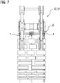
- FIG. 7 shows a - correspondingly formed - cold strand 51 for measuring a casting gap 2 in a continuous caster.
- this measuring system has cold rolling train "51 chain-connected cold strand members 55, in which a 55 three measuring tongs 1 - symmetrically arranged over the width - are installed.
Landscapes
- Engineering & Computer Science (AREA)
- Mechanical Engineering (AREA)
- Physics & Mathematics (AREA)
- General Physics & Mathematics (AREA)
- Continuous Casting (AREA)
- Length Measuring Devices With Unspecified Measuring Means (AREA)
- A Measuring Device Byusing Mechanical Method (AREA)
Priority Applications (5)
| Application Number | Priority Date | Filing Date | Title |
|---|---|---|---|
| EP17184150.5A EP3437758A1 (fr) | 2017-08-01 | 2017-08-01 | Dispositif de mesure permettant la mesure d'une fente de coulée d'une installation de coulée continue et utilisation dudit dispositif de mesure permettant la mesure d'une fente de coulée |
| CN201880050516.3A CN110914006B (zh) | 2017-08-01 | 2018-07-24 | 对连铸设备中的浇铸缝隙进行测量的测量装置以及这种测量装置用于测量浇铸缝隙的应用 |
| EP18740868.7A EP4013561A1 (fr) | 2017-08-01 | 2018-07-24 | Dispositif de mesure pour la mesure d'une fente de coulée sur une installation de coulée continue et utilisation de ce dispositif de mesure pour la mesure d'une fente de coulée |
| KR1020197038166A KR102530547B1 (ko) | 2017-08-01 | 2018-07-24 | 연속 주조 시스템에서 주조 갭을 측정하기 위한 측정 장치 및 주조 갭을 측정하기 위한 이와 같은 측정 장치의 용도 |
| PCT/EP2018/069977 WO2019025228A1 (fr) | 2017-08-01 | 2018-07-24 | Dispositif de mesure pour la mesure d'une fente de coulée sur une installation de coulée continue et utilisation de ce dispositif de mesure pour la mesure d'une fente de coulée |
Applications Claiming Priority (1)
| Application Number | Priority Date | Filing Date | Title |
|---|---|---|---|
| EP17184150.5A EP3437758A1 (fr) | 2017-08-01 | 2017-08-01 | Dispositif de mesure permettant la mesure d'une fente de coulée d'une installation de coulée continue et utilisation dudit dispositif de mesure permettant la mesure d'une fente de coulée |
Publications (1)
| Publication Number | Publication Date |
|---|---|
| EP3437758A1 true EP3437758A1 (fr) | 2019-02-06 |
Family
ID=59506134
Family Applications (2)
| Application Number | Title | Priority Date | Filing Date |
|---|---|---|---|
| EP17184150.5A Withdrawn EP3437758A1 (fr) | 2017-08-01 | 2017-08-01 | Dispositif de mesure permettant la mesure d'une fente de coulée d'une installation de coulée continue et utilisation dudit dispositif de mesure permettant la mesure d'une fente de coulée |
| EP18740868.7A Pending EP4013561A1 (fr) | 2017-08-01 | 2018-07-24 | Dispositif de mesure pour la mesure d'une fente de coulée sur une installation de coulée continue et utilisation de ce dispositif de mesure pour la mesure d'une fente de coulée |
Family Applications After (1)
| Application Number | Title | Priority Date | Filing Date |
|---|---|---|---|
| EP18740868.7A Pending EP4013561A1 (fr) | 2017-08-01 | 2018-07-24 | Dispositif de mesure pour la mesure d'une fente de coulée sur une installation de coulée continue et utilisation de ce dispositif de mesure pour la mesure d'une fente de coulée |
Country Status (4)
| Country | Link |
|---|---|
| EP (2) | EP3437758A1 (fr) |
| KR (1) | KR102530547B1 (fr) |
| CN (1) | CN110914006B (fr) |
| WO (1) | WO2019025228A1 (fr) |
Citations (3)
| Publication number | Priority date | Publication date | Assignee | Title |
|---|---|---|---|---|
| JPS54151515A (en) * | 1978-05-22 | 1979-11-28 | Nippon Steel Corp | Measuring instruments for roll gap and roll alignment in continuous casting machine |
| US4294305A (en) * | 1978-10-25 | 1981-10-13 | Kawasaki Steel Corporation | Roll gap measuring device for continuous casting machine |
| JPS571554A (en) * | 1980-06-02 | 1982-01-06 | Nippon Steel Corp | Method and device for measuring roll gap of continuously cast ingot guide roll |
Family Cites Families (10)
| Publication number | Priority date | Publication date | Assignee | Title |
|---|---|---|---|---|
| FR2317032A1 (fr) * | 1975-07-08 | 1977-02-04 | Pechiney Aluminium | Procede de coulee continue dans la jante d'une roue |
| JPS5568162A (en) * | 1978-11-14 | 1980-05-22 | Kawasaki Steel Corp | Roll gap measuring method for continuous casting machine |
| JPH07115139B2 (ja) * | 1990-05-25 | 1995-12-13 | 住友金属工業株式会社 | 連続鋳造用ロール対間隔測定方法・装置 |
| CN201463868U (zh) * | 2009-07-28 | 2010-05-12 | 宝山钢铁股份有限公司 | 连铸机辊缝测试装置 |
| CN201543791U (zh) * | 2009-10-15 | 2010-08-11 | 宝山钢铁股份有限公司 | 连铸机铸辊辊缝仪 |
| CN102039390B (zh) * | 2010-11-11 | 2012-08-15 | 哈尔滨工业大学 | 冶金铸机双摆角式辊缝测量装置 |
| JP2014063628A (ja) * | 2012-09-21 | 2014-04-10 | Jfe Steel Corp | バッテリー電源の劣化予兆検知方法および装置 |
| KR20140069502A (ko) * | 2012-11-29 | 2014-06-10 | 주식회사 포스코 | 연속 주조 설비의 롤 정렬상태 및 갭 측정장치 |
| CN204535684U (zh) * | 2015-04-14 | 2015-08-05 | 武汉中飞扬测控工程有限公司 | 可预收缩手持式辊缝仪 |
| CN106181578B (zh) * | 2016-07-28 | 2018-08-21 | 西安交通大学 | 一种测量扭矩和轴向力的旋转式铣削力传感器 |
-
2017
- 2017-08-01 EP EP17184150.5A patent/EP3437758A1/fr not_active Withdrawn
-
2018
- 2018-07-24 CN CN201880050516.3A patent/CN110914006B/zh active Active
- 2018-07-24 EP EP18740868.7A patent/EP4013561A1/fr active Pending
- 2018-07-24 KR KR1020197038166A patent/KR102530547B1/ko active Active
- 2018-07-24 WO PCT/EP2018/069977 patent/WO2019025228A1/fr not_active Ceased
Patent Citations (3)
| Publication number | Priority date | Publication date | Assignee | Title |
|---|---|---|---|---|
| JPS54151515A (en) * | 1978-05-22 | 1979-11-28 | Nippon Steel Corp | Measuring instruments for roll gap and roll alignment in continuous casting machine |
| US4294305A (en) * | 1978-10-25 | 1981-10-13 | Kawasaki Steel Corporation | Roll gap measuring device for continuous casting machine |
| JPS571554A (en) * | 1980-06-02 | 1982-01-06 | Nippon Steel Corp | Method and device for measuring roll gap of continuously cast ingot guide roll |
Also Published As
| Publication number | Publication date |
|---|---|
| WO2019025228A1 (fr) | 2019-02-07 |
| CN110914006B (zh) | 2022-08-12 |
| CN110914006A (zh) | 2020-03-24 |
| KR20200037752A (ko) | 2020-04-09 |
| EP4013561A1 (fr) | 2022-06-22 |
| KR102530547B1 (ko) | 2023-05-08 |
Similar Documents
| Publication | Publication Date | Title |
|---|---|---|
| EP2024110B1 (fr) | Dispositif de mesure de la largeur et/ou de la position d'une bande métallique ou d'une brame | |
| DE3841439C2 (fr) | ||
| DE8523750U1 (de) | Rollenführung, insbesondere für Knüppel, Stab- und Drahtwalzgerüste | |
| DE2633379B2 (de) | Vorrichtung zum Vermessen der Geometrie des Formhohlraumes von Stranggießkokillen | |
| EP0257383B1 (fr) | Dispositif de réglage axial des cylindres des cages de laminoir pour la fabrication des profilés en acier | |
| DE102007051237A1 (de) | Verfahren und Vorrichtung zum Einstellen des Lagerspiels oder der Vorspannung von Wälzlageranordnungen | |
| DE2529552B2 (de) | Vorrichtung zum messen der auf ein drehteil ausgeuebten radialkraft | |
| EP3212351B1 (fr) | Unité de rouleau de guidage de barre destinée à une machine pour la coulée continue | |
| EP1817125A2 (fr) | Procede et segment de rouleaux pour determiner la solidification a coeur et/ou l'extremite du cratere liquide lors de la coulee continue de metaux, notamment de materiaux a base d'acier | |
| EP3623076B1 (fr) | Dispositif de mesure et méthode de mesure permettant de déterminer l'inclinaison de coté court et la largeur de coulée d'une lingotière | |
| DE202008005154U1 (de) | Vorrichtung zur Überprüfung der Maß-, Form- und Lagetoleranzen von Konturen an Werkstücken | |
| WO2013041083A2 (fr) | Installation et procédé de laminage | |
| DE2331916A1 (de) | Vorrichtung zum messen der seitlichen lage eines gleises zum nachbargleis | |
| DE2807496C3 (de) | Vorrichtung zur konstanthaltung des Elevationswinkels des Beobachtungsstrahls eines von einem Fahrzeug getragenen Periskopsystems | |
| AT524361B1 (de) | Wälzlageranordnung | |
| EP3546086B1 (fr) | Procédé destiné à la coulée continue d'une structure métallique à l'aide d'une lingotière et d'une brique de coulée | |
| EP4013561A1 (fr) | Dispositif de mesure pour la mesure d'une fente de coulée sur une installation de coulée continue et utilisation de ce dispositif de mesure pour la mesure d'une fente de coulée | |
| EP0301651B1 (fr) | Dispositif pour positionner un capteur | |
| DE2432856A1 (de) | Diamant-abrichtvorrichtung | |
| DE2322474A1 (de) | Ueberwachungsvorrichtung | |
| DE3512290A1 (de) | Messeinrichtung zum messen des spaltes zwischen zwei walzen oder rollen sowie verfahren zur durchfuehrung der messung | |
| DE102016003043B4 (de) | Messgerät zum Einmessen von Rotationskörper-Makrogeometrie | |
| DE2645022B2 (de) | Meßvorrichtung für drehgelagerte Arbeitswalzen, insbesondere für Stütz-, Treib- und Richtwalzen in MetallstranggieBanlagen | |
| DE4204562A1 (de) | Rohrmessvorrichtung | |
| EP3663017A1 (fr) | Surveillance d'un état d'usure d'un rouleau de guidage de barre coulée d'une installation de coulée continue |
Legal Events
| Date | Code | Title | Description |
|---|---|---|---|
| PUAI | Public reference made under article 153(3) epc to a published international application that has entered the european phase |
Free format text: ORIGINAL CODE: 0009012 |
|
| AK | Designated contracting states |
Kind code of ref document: A1 Designated state(s): AL AT BE BG CH CY CZ DE DK EE ES FI FR GB GR HR HU IE IS IT LI LT LU LV MC MK MT NL NO PL PT RO RS SE SI SK SM TR |
|
| AX | Request for extension of the european patent |
Extension state: BA ME |
|
| STAA | Information on the status of an ep patent application or granted ep patent |
Free format text: STATUS: THE APPLICATION IS DEEMED TO BE WITHDRAWN |
|
| 18D | Application deemed to be withdrawn |
Effective date: 20190807 |