EP3437792A1 - Verfahren zur herstellung einer turbinenschaufel - Google Patents
Verfahren zur herstellung einer turbinenschaufel Download PDFInfo
- Publication number
- EP3437792A1 EP3437792A1 EP18174829.4A EP18174829A EP3437792A1 EP 3437792 A1 EP3437792 A1 EP 3437792A1 EP 18174829 A EP18174829 A EP 18174829A EP 3437792 A1 EP3437792 A1 EP 3437792A1
- Authority
- EP
- European Patent Office
- Prior art keywords
- segment
- alloy
- blade
- section
- joint
- Prior art date
- Legal status (The legal status is an assumption and is not a legal conclusion. Google has not performed a legal analysis and makes no representation as to the accuracy of the status listed.)
- Withdrawn
Links
- 238000004519 manufacturing process Methods 0.000 title claims abstract description 24
- 229910045601 alloy Inorganic materials 0.000 claims abstract description 121
- 239000000956 alloy Substances 0.000 claims abstract description 121
- 238000005304 joining Methods 0.000 claims abstract description 19
- 238000000034 method Methods 0.000 claims description 20
- 238000010438 heat treatment Methods 0.000 claims description 19
- PXHVJJICTQNCMI-UHFFFAOYSA-N Nickel Chemical compound [Ni] PXHVJJICTQNCMI-UHFFFAOYSA-N 0.000 claims description 18
- 230000008569 process Effects 0.000 claims description 14
- 239000013078 crystal Substances 0.000 claims description 13
- 229910000601 superalloy Inorganic materials 0.000 claims description 13
- 229910052759 nickel Inorganic materials 0.000 claims description 9
- 229910017052 cobalt Inorganic materials 0.000 claims description 7
- 239000010941 cobalt Substances 0.000 claims description 7
- GUTLYIVDDKVIGB-UHFFFAOYSA-N cobalt atom Chemical compound [Co] GUTLYIVDDKVIGB-UHFFFAOYSA-N 0.000 claims description 7
- 238000003466 welding Methods 0.000 claims description 6
- 238000009792 diffusion process Methods 0.000 claims description 3
- 238000010894 electron beam technology Methods 0.000 claims description 3
- 239000007791 liquid phase Substances 0.000 claims description 3
- 230000003647 oxidation Effects 0.000 claims description 3
- 238000007254 oxidation reaction Methods 0.000 claims description 3
- 238000001556 precipitation Methods 0.000 claims description 3
- 239000012720 thermal barrier coating Substances 0.000 claims description 3
- 230000001052 transient effect Effects 0.000 claims description 3
- 239000007789 gas Substances 0.000 description 26
- 230000008901 benefit Effects 0.000 description 15
- 229910001152 Bi alloy Inorganic materials 0.000 description 14
- 239000000463 material Substances 0.000 description 13
- 238000012360 testing method Methods 0.000 description 7
- 238000013461 design Methods 0.000 description 6
- 238000013101 initial test Methods 0.000 description 5
- 229910000838 Al alloy Inorganic materials 0.000 description 2
- 230000009286 beneficial effect Effects 0.000 description 2
- 239000012530 fluid Substances 0.000 description 2
- 239000000446 fuel Substances 0.000 description 2
- 229910001026 inconel Inorganic materials 0.000 description 2
- 230000014759 maintenance of location Effects 0.000 description 2
- 239000007787 solid Substances 0.000 description 2
- 229910001247 waspaloy Inorganic materials 0.000 description 2
- 239000004215 Carbon black (E152) Substances 0.000 description 1
- 239000000654 additive Substances 0.000 description 1
- 230000000996 additive effect Effects 0.000 description 1
- -1 but not limited to Inorganic materials 0.000 description 1
- 239000011248 coating agent Substances 0.000 description 1
- 238000000576 coating method Methods 0.000 description 1
- 239000000567 combustion gas Substances 0.000 description 1
- 238000004891 communication Methods 0.000 description 1
- 230000006835 compression Effects 0.000 description 1
- 238000007906 compression Methods 0.000 description 1
- 238000007796 conventional method Methods 0.000 description 1
- 238000005260 corrosion Methods 0.000 description 1
- 230000007797 corrosion Effects 0.000 description 1
- 230000008878 coupling Effects 0.000 description 1
- 238000010168 coupling process Methods 0.000 description 1
- 238000005859 coupling reaction Methods 0.000 description 1
- 239000000284 extract Substances 0.000 description 1
- 230000012447 hatching Effects 0.000 description 1
- 229930195733 hydrocarbon Natural products 0.000 description 1
- 150000002430 hydrocarbons Chemical class 0.000 description 1
- 238000012986 modification Methods 0.000 description 1
- 230000004048 modification Effects 0.000 description 1
- 238000012545 processing Methods 0.000 description 1
- 230000009467 reduction Effects 0.000 description 1
- 230000004044 response Effects 0.000 description 1
- 230000003068 static effect Effects 0.000 description 1
- 239000000126 substance Substances 0.000 description 1
Images


Classifications
-
- F—MECHANICAL ENGINEERING; LIGHTING; HEATING; WEAPONS; BLASTING
- F01—MACHINES OR ENGINES IN GENERAL; ENGINE PLANTS IN GENERAL; STEAM ENGINES
- F01D—NON-POSITIVE DISPLACEMENT MACHINES OR ENGINES, e.g. STEAM TURBINES
- F01D5/00—Blades; Blade-carrying members; Heating, heat-insulating, cooling or antivibration means on the blades or the members
- F01D5/12—Blades
- F01D5/28—Selecting particular materials; Particular measures relating thereto; Measures against erosion or corrosion
- F01D5/288—Protective coatings for blades
-
- B—PERFORMING OPERATIONS; TRANSPORTING
- B23—MACHINE TOOLS; METAL-WORKING NOT OTHERWISE PROVIDED FOR
- B23P—METAL-WORKING NOT OTHERWISE PROVIDED FOR; COMBINED OPERATIONS; UNIVERSAL MACHINE TOOLS
- B23P15/00—Making specific metal objects by operations not covered by a single other subclass or a group in this subclass
- B23P15/04—Making specific metal objects by operations not covered by a single other subclass or a group in this subclass turbine or like blades from several pieces
-
- F—MECHANICAL ENGINEERING; LIGHTING; HEATING; WEAPONS; BLASTING
- F01—MACHINES OR ENGINES IN GENERAL; ENGINE PLANTS IN GENERAL; STEAM ENGINES
- F01D—NON-POSITIVE DISPLACEMENT MACHINES OR ENGINES, e.g. STEAM TURBINES
- F01D5/00—Blades; Blade-carrying members; Heating, heat-insulating, cooling or antivibration means on the blades or the members
- F01D5/12—Blades
- F01D5/14—Form or construction
- F01D5/147—Construction, i.e. structural features, e.g. of weight-saving hollow blades
-
- F—MECHANICAL ENGINEERING; LIGHTING; HEATING; WEAPONS; BLASTING
- F01—MACHINES OR ENGINES IN GENERAL; ENGINE PLANTS IN GENERAL; STEAM ENGINES
- F01D—NON-POSITIVE DISPLACEMENT MACHINES OR ENGINES, e.g. STEAM TURBINES
- F01D5/00—Blades; Blade-carrying members; Heating, heat-insulating, cooling or antivibration means on the blades or the members
- F01D5/12—Blades
- F01D5/28—Selecting particular materials; Particular measures relating thereto; Measures against erosion or corrosion
-
- F—MECHANICAL ENGINEERING; LIGHTING; HEATING; WEAPONS; BLASTING
- F01—MACHINES OR ENGINES IN GENERAL; ENGINE PLANTS IN GENERAL; STEAM ENGINES
- F01D—NON-POSITIVE DISPLACEMENT MACHINES OR ENGINES, e.g. STEAM TURBINES
- F01D9/00—Stators
- F01D9/02—Nozzles; Nozzle boxes; Stator blades; Guide conduits, e.g. individual nozzles
-
- F—MECHANICAL ENGINEERING; LIGHTING; HEATING; WEAPONS; BLASTING
- F04—POSITIVE - DISPLACEMENT MACHINES FOR LIQUIDS; PUMPS FOR LIQUIDS OR ELASTIC FLUIDS
- F04D—NON-POSITIVE-DISPLACEMENT PUMPS
- F04D29/00—Details, component parts, or accessories
- F04D29/26—Rotors specially for elastic fluids
- F04D29/32—Rotors specially for elastic fluids for axial flow pumps
- F04D29/321—Rotors specially for elastic fluids for axial flow pumps for axial flow compressors
- F04D29/324—Blades
-
- F—MECHANICAL ENGINEERING; LIGHTING; HEATING; WEAPONS; BLASTING
- F05—INDEXING SCHEMES RELATING TO ENGINES OR PUMPS IN VARIOUS SUBCLASSES OF CLASSES F01-F04
- F05D—INDEXING SCHEME FOR ASPECTS RELATING TO NON-POSITIVE-DISPLACEMENT MACHINES OR ENGINES, GAS-TURBINES OR JET-PROPULSION PLANTS
- F05D2220/00—Application
- F05D2220/30—Application in turbines
- F05D2220/32—Application in turbines in gas turbines
-
- F—MECHANICAL ENGINEERING; LIGHTING; HEATING; WEAPONS; BLASTING
- F05—INDEXING SCHEMES RELATING TO ENGINES OR PUMPS IN VARIOUS SUBCLASSES OF CLASSES F01-F04
- F05D—INDEXING SCHEME FOR ASPECTS RELATING TO NON-POSITIVE-DISPLACEMENT MACHINES OR ENGINES, GAS-TURBINES OR JET-PROPULSION PLANTS
- F05D2230/00—Manufacture
- F05D2230/20—Manufacture essentially without removing material
- F05D2230/23—Manufacture essentially without removing material by permanently joining parts together
- F05D2230/232—Manufacture essentially without removing material by permanently joining parts together by welding
- F05D2230/233—Electron beam welding
-
- F—MECHANICAL ENGINEERING; LIGHTING; HEATING; WEAPONS; BLASTING
- F05—INDEXING SCHEMES RELATING TO ENGINES OR PUMPS IN VARIOUS SUBCLASSES OF CLASSES F01-F04
- F05D—INDEXING SCHEME FOR ASPECTS RELATING TO NON-POSITIVE-DISPLACEMENT MACHINES OR ENGINES, GAS-TURBINES OR JET-PROPULSION PLANTS
- F05D2230/00—Manufacture
- F05D2230/20—Manufacture essentially without removing material
- F05D2230/23—Manufacture essentially without removing material by permanently joining parts together
- F05D2230/232—Manufacture essentially without removing material by permanently joining parts together by welding
- F05D2230/236—Diffusion bonding
-
- F—MECHANICAL ENGINEERING; LIGHTING; HEATING; WEAPONS; BLASTING
- F05—INDEXING SCHEMES RELATING TO ENGINES OR PUMPS IN VARIOUS SUBCLASSES OF CLASSES F01-F04
- F05D—INDEXING SCHEME FOR ASPECTS RELATING TO NON-POSITIVE-DISPLACEMENT MACHINES OR ENGINES, GAS-TURBINES OR JET-PROPULSION PLANTS
- F05D2230/00—Manufacture
- F05D2230/20—Manufacture essentially without removing material
- F05D2230/23—Manufacture essentially without removing material by permanently joining parts together
- F05D2230/232—Manufacture essentially without removing material by permanently joining parts together by welding
- F05D2230/239—Inertia or friction welding
-
- F—MECHANICAL ENGINEERING; LIGHTING; HEATING; WEAPONS; BLASTING
- F05—INDEXING SCHEMES RELATING TO ENGINES OR PUMPS IN VARIOUS SUBCLASSES OF CLASSES F01-F04
- F05D—INDEXING SCHEME FOR ASPECTS RELATING TO NON-POSITIVE-DISPLACEMENT MACHINES OR ENGINES, GAS-TURBINES OR JET-PROPULSION PLANTS
- F05D2230/00—Manufacture
- F05D2230/40—Heat treatment
- F05D2230/41—Hardening; Annealing
- F05D2230/411—Precipitation hardening
-
- F—MECHANICAL ENGINEERING; LIGHTING; HEATING; WEAPONS; BLASTING
- F05—INDEXING SCHEMES RELATING TO ENGINES OR PUMPS IN VARIOUS SUBCLASSES OF CLASSES F01-F04
- F05D—INDEXING SCHEME FOR ASPECTS RELATING TO NON-POSITIVE-DISPLACEMENT MACHINES OR ENGINES, GAS-TURBINES OR JET-PROPULSION PLANTS
- F05D2300/00—Materials; Properties thereof
- F05D2300/10—Metals, alloys or intermetallic compounds
- F05D2300/17—Alloys
- F05D2300/175—Superalloys
-
- F—MECHANICAL ENGINEERING; LIGHTING; HEATING; WEAPONS; BLASTING
- F05—INDEXING SCHEMES RELATING TO ENGINES OR PUMPS IN VARIOUS SUBCLASSES OF CLASSES F01-F04
- F05D—INDEXING SCHEME FOR ASPECTS RELATING TO NON-POSITIVE-DISPLACEMENT MACHINES OR ENGINES, GAS-TURBINES OR JET-PROPULSION PLANTS
- F05D2300/00—Materials; Properties thereof
- F05D2300/10—Metals, alloys or intermetallic compounds
- F05D2300/17—Alloys
- F05D2300/177—Ni - Si alloys
-
- F—MECHANICAL ENGINEERING; LIGHTING; HEATING; WEAPONS; BLASTING
- F05—INDEXING SCHEMES RELATING TO ENGINES OR PUMPS IN VARIOUS SUBCLASSES OF CLASSES F01-F04
- F05D—INDEXING SCHEME FOR ASPECTS RELATING TO NON-POSITIVE-DISPLACEMENT MACHINES OR ENGINES, GAS-TURBINES OR JET-PROPULSION PLANTS
- F05D2300/00—Materials; Properties thereof
- F05D2300/60—Properties or characteristics given to material by treatment or manufacturing
- F05D2300/606—Directionally-solidified crystalline structures
Definitions
- the present disclosure is directed to a gas turbine engine. More particularly, to a turbine blade and a method of fabricating a turbine blade for a gas turbine engine.
- Gas turbine engines include a compressor section, a turbine section, and a combustor section.
- the compressor section pressurizes air.
- the combustor section burns a hydrocarbon fuel in the presence of the pressurized air.
- the turbine section extracts energy from combustion gases.
- Blades and vanes generally reside in the turbine section of the gas turbine engine.
- Conventional blades are generally fabricated from a single alloy which may not be optimum for all applications. Various regions of conventional blades are often limited by strength or life of the crystal material used to fabricate the blades.
- a method of manufacturing a blade includes forming a first segment of a blade using a first alloy, forming a second segment of a blade using a second alloy, determining a joint location of the first segment of the blade, and joining the first segment and the second segment at the joint location of the first segment.
- the first alloy is at least one of a cobalt superalloy and the second alloy is at least one of a nickel-based alloy and a superalloy different from an alloy of the first alloy.
- the second alloy is at least one of a nickel-based alloy and a superalloy different from an alloy of the first alloy.
- the joining the first segment and the second segment includes at least one of frictional welding, diffusion bonding, transient liquid phase bonding, or electron beam welding.
- the first alloy is a single crystal alloy and the second alloy is a single crystal alloy different from the first alloy.
- the first segment is an attachment section and the second segment is an airfoil section.
- the first alloy and the second alloy are directionally solidified alloys.
- the first segment of the blade and the second segment of the blade meet at a joint region, wherein the joint region is at least one of an airfoil root joint or a mid-platform joint.
- the method of manufacturing further includes performing a heat treatment on the blade.
- the heat treatment includes at least one of a solution heat treatment, a precipitation heat treatment, or stress relief.
- a segmented portion of a gas turbine engine includes a first segment, a second segment coupled to the first segment, wherein the first segment is made of a first alloy and the second segment is a second alloy, and wherein the first alloy is different from the second alloy, and a joint region, wherein the joint region includes a location where the first segment and the second segment meet.
- the first segment and the second segment are joined together to form a blade.
- first segment and the second segment are joined together to form a vane.
- first segment comprises an attachment section and a platform section.
- the second segment comprises an airfoil and a shroud.
- the first alloy is a single crystal alloy and the second alloy has equiaxed crystals.
- the blade has at least one of a single or double knife edge.
- the first segment and the second segment are coupled together at the joint section placed in a platform section.
- At least a portion of a heat treatment of the segmented portion occurs after a joining process or before the joining process for one or more of the first alloy and the second alloy.
- a blade for a gas turbine engine includes a first segment including an attachment section, a platform section, wherein the first segment is made of a first alloy, and a second segment including a airfoil section, a tip shroud, and an airfoil root joint, wherein the second segment is made of a second alloy distinct from the first alloy, and wherein the second segment is coupled to the first segment at the airfoil root joint.
- any reference to attached, fixed, connected, or the like may include permanent, removable, temporary, partial, full, and/or any other possible attachment option. Additionally, any reference to without contact (or similar phrases) may also include reduced contact or minimal contact.
- Cross hatching lines may be used throughout the figures to denote different parts but not necessarily to denote the same or different materials.
- aft refers to the direction associated with the exhaust (e.g., the back end) of a gas turbine engine.
- forward refers to the direction associated with the intake (e.g., the front end) of a gas turbine engine.
- An A-R-C axis is shown in various drawings to illustrate the axial, radial, and circumferential directions, respectively.
- radially outward refers to the direction generally away from the axis of rotation of a turbine engine.
- radially inward refers to the direction generally towards the axis of rotation of a turbine engine.
- Multi-alloy blades may be manufactured so that a single blade comprises multiple materials and, accordingly, blade portions may be created using materials that suit the particular use case for that portion of the blade.
- Conventional joinery and conventional materials may not be sufficient to create a blade for use in a demand environment, such as, a gas turbine engine.
- solid state joining processes may be employed to join at least two different alloy together to form a single blade.
- the use of multiple alloys in turbine blade manufacturing may be beneficial as a blade may be produced that, in various embodiments, has both lower density and lower weight.
- Gas turbine engine 20 may be a two-spool turbofan that generally incorporates a fan section 122, a compressor section 124, a combustor section 126 and a turbine section 128.
- Alternative engines may include, for example, an augmentor section among other systems or features.
- fan section 122 can drive fluid (e.g., air) along a path of bypass airflow B while compressor section 124 can drive fluid along a core flowpath C for compression and communication into combustor section 126 then expansion through turbine section 128.
- fluid e.g., air
- compressor section 124 can drive fluid along a core flowpath C for compression and communication into combustor section 126 then expansion through turbine section 128.
- Gas turbine engine 20 may generally comprise a low speed spool 130 and a high speed spool 132 mounted for rotation about an engine central longitudinal axis A-A' relative to an engine static structure 136 (also referred to as an engine casing structure) via several bearing systems 138, 138-1, and 138-2.
- Engine central longitudinal axis A-A' is oriented in the z direction on the provided xyz axes. It should be understood that various bearing systems 138 at various locations may alternatively or additionally be provided, including for example, bearing system 138, bearing system 138-1, and bearing system 138-2.
- Low speed spool 130 may generally comprise an inner shaft 140 that interconnects a fan 142, a low pressure compressor 144, and a low pressure turbine 146.
- Inner shaft 140 may be connected to fan 142 through a geared architecture 48 that can drive fan 142 at a lower speed than low speed spool 130.
- Geared architecture 148 may comprise a gear assembly 160 enclosed within a gear housing 162.
- Gear assembly 160 couples inner shaft 140 to a rotating fan structure.
- High speed spool 132 may comprise an outer shaft 150 that interconnects a high pressure compressor 152 and high pressure turbine 154. As used herein, a "high pressure" compressor or turbine experiences a higher pressure than a corresponding "low pressure” compressor or turbine.
- a combustor 156 may be located between high pressure compressor 152 and high pressure turbine 154.
- a mid-turbine frame 157 of engine casing structure 136 may be located generally between high pressure turbine 154 and low pressure turbine 146.
- Mid-turbine frame 157 may support one or more bearing systems 138 in turbine section 128.
- Inner shaft 140 and outer shaft 150 may be concentric and rotate via bearing systems 138 about the engine central longitudinal axis A-A', which is collinear with their longitudinal axes.
- the core airflow C may be compressed by low pressure compressor 144 then high pressure compressor 152, mixed and burned with fuel in combustor 156, then expanded over high pressure turbine 154 and low pressure turbine 146. Turbines 146, 154 rotationally drive the respective low speed spool F and high speed spool 132 in response to the expansion.
- the gas turbine engine 20 may be, for example, a high-bypass ratio geared engine. In various embodiments, the bypass ratio of the gas turbine engine 20 may be greater than about six (6). In various embodiments, the bypass ratio of the gas turbine engine 20 may be greater than ten (10).
- the geared architecture 148 may be an epicyclic gear train, such as a star gear system (sun gear in meshing engagement with a plurality of star gears supported by a carrier and in meshing engagement with a ring gear) or other gear system.
- the geared architecture 148 may have a gear reduction ratio of greater than about 2.3 and the low pressure turbine 146 may have a pressure ratio that is greater than about five (5).
- the bypass ratio of the gas turbine engine 20 is greater than about ten (10:1).
- the diameter of the fan 142 may be significantly larger than that of the low pressure compressor 144, and the low pressure turbine 146 may have a pressure ratio that is greater than about five (5:1).
- the low pressure turbine 146 pressure ratio may be measured prior to the inlet of the low pressure turbine 146 as related to the pressure at the outlet of the low pressure turbine 146 prior to an exhaust nozzle. It should be understood, however, that the above parameters are exemplary of various embodiments of a suitable geared architecture engine and that the present disclosure contemplates other gas turbine engines including direct drive turbofans.
- a gas turbine engine may comprise an industrial gas turbine (IGT) or a geared engine, such as a geared turbofan, or non-geared engine, such as a turbofan, a turboshaft, or may comprise any gas turbine engine as desired.
- Rotor assembly 30 such as that of a stage of the LPT is illustrated.
- Rotor assembly 30 includes a plurality of blades 32 circumferentially disposed around a respective rotor disk 34.
- the rotor disk 34 generally includes a hub 36, a rim 38, and a web 40 which extends therebetween. It should be understood that a multiple of disks may be contained within each engine section and that although one blade from the LPT section is illustrated and described in the disclosed embodiment, other sections will also benefit herefrom.
- rotor assembly 30 Although a particular rotor assembly 30 is illustrated and described in the disclosed embodiment, other sections which have other blades such as fan blades, low pressure compressor blades, high pressure compressor blades, high pressure turbine blades, low pressure turbine blades, and power turbine blades may also benefit herefrom.
- each blade 32 generally includes an attachment section 42, a platform section 44, and an airfoil section 46 along a blade axis B.
- Each of the blades 32 is received within a blade retention slot 48 (as illustrated in Figure 2 ) formed within the rim 38 of the rotor disk.
- airfoil section 46 is coupled to platform section 44. Airfoil section 46 extends from platform section 44.
- the blade retention slot 48 includes a contour such as a dove-tail, fir-tree or bulb type which corresponds with a contour of the attachment section 42 to provide engagement therewith.
- a distal end section 46T includes a tip shroud 50 that may include rails 52 which define knife edge seals which interface with stationary engine structure.
- the rails 52 define annular knife seals when assembled to the rotor disk 34. That is, the tip shroud 50 on one blade 32 interfaces with the tip shroud 50 on an adjacent blade 32 to form an annular turbine ring tip shroud.
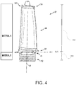
- a first segment 316, of turbine blade 32 which may include attachment section 42 and platform section 44, is formed using a first alloy.
- a second segment 314, which may include airfoil section 46 and tip shroud 50, is formed using a second alloy.
- the first alloy may be, for example, an aluminum alloy or a superalloy, such as a cobalt or a nickel-based alloy.
- the second alloy, different from the first alloy may be, for example, an aluminum alloy or a superalloy, such as a cobalt or a nickel-based alloy.
- a superalloy may generally be an alloy that exhibits additional characteristics over general alloys. For example, a superalloy may have greater mechanical strength, stability, and corrosion resistance such as INCONEL, WASPALOY, PWA 658, etc.
- a first segment 416, of turbine blade 32 which may include attachment section 42 and a portion of platform section 44, is formed using a first alloy.
- the first alloy may be, for example, a superalloy, such as a cobalt or a nickel-based alloy.
- the second alloy, selected to be different from the first alloy may be, for example, a superalloy, such as a cobalt or a nickel-based alloy.
- first segment 316, 416 is formed in a case or casing using the first alloy.
- Second segment 314, 414 is formed in a second case or casing using the second alloy.
- the joining process may produce acceptable material properties in and around a joint region (e.g, 416) or threshold location of the first segment.
- the processing order depends upon which path produces the desired combination of properties at, for example, both the joint and in the parent materials.
- a threshold location of the first segment may be determined to be, for example, a location with high structural margins and low stress.
- Such a location may be determined by performing a series of stress tests of the first segment to determine the location where the first segment may be coupled to the second segment. As described below and in conjunction with Figures 3 and 4 , the threshold location is at a designated joint location.
- one or more solid state processes such as frictional welding, diffusion bonding, transient liquid phase bonding, and/or electron beam welding may be used to join various segments of blade 32.
- an additive manufacturing process may be utilized to form blade 32.
- the heat treatment of the turbine blade occurs after a joining process.
- the heat treatment includes at least one of a solution heat treatment, a precipitation heat treatment, or stress relief.
- blade 32 is formed as a bi-alloy turbine blade whereby multiple elements of different alloys are fabricated together to form a single blade 32.
- a plurality of alloys with a plurality of segments may be added such that more than two alloys are utilized.
- a multi-segment blade with three alloys may fabricated together to form a single blade 32.
- blade 32 may contain a first alloy for an attachment region of blade 32 and a second unique alloy for the airfoil section 46 of blade 32.
- a tri-segment blade may be comprised of two or three alloys.
- Partial or total heat treatment of the two or three alloy segments may occur prior to joining of the segments.
- a partial heat treatment of the segments may occur prior to joining the segments and the remainder of the heat treatment may occur after joining the segments, when, for example, all segments are joined into a single piece.
- blade 32 may be coated with an oxidation resistance or thermal barrier coating.
- the coating of blade 32 with an oxidation resistance or thermal barrier coating can also serve as a step in heat treatment or stress relief.
- blade 32 may utilize a single crystal alloy for the attachment region including platform section 44 with an equiax alloy being utilized for airfoil section 46.
- the equiax alloy may include superalloys such as but not limited to, cobalt and nickel-based alloys, such as those sold under the trademarks INCONEL, WASPALOY, and PWA 658 alloys, etc.
- a joint region or threshold location includes the location where the first unique alloy is coupled to the second unique alloy.
- the joint region may include an airfoil root joint 318 placed in an airfoil root platform (airfoil section 314, 414).
- the joint region may include a mid-platform joint 418 placed in a mid-platform (platform section 314, 414).
- the regions below the platform are often limited by strength or life and want to be a single crystal material. Therefore, introduction of bi-alloy designs with regions below the platform (e.g., with mid-platform joint) are presented. Above platform regions can be creep limited or may lack the benefit from a material of lower density or higher elastic modulus. Therefore, in some embodiments of bi-alloy designs are introduced with a airflow root joint.
- downstream components may benefit from reduced blade weight in that in 1) containment structures can be lightened (or thinned) and 2) lower live rim pull can result in lightened rotors or through simplified attachment design. Note that additional benefits may be achieved by the blade in blade tuning by placing materials of preferential density and modulus in influential locations for critical modes.
- bi-alloy turbine blades may be beneficial to the design of gas engine 10.
- bi-alloy turbine blades offer reduced weight, improved rotor dynamics, which may in turn reduce turbine stage count, and provide tuning benefits.
- Conventional blades that are fabricated from a single alloy which is often not the optimum for all locations.
- initial testing indicating the benefits over conventional methods were conducted.
- a 3.25% decrease in weight was achieved in using a bi-alloy blade design with mid-platform joint as illustrated in the tables below.
- Table 2 below illustrates initial test results using bi-alloys with BM 1.31.
- a 7.23% decrease in weight was achieved using another bi-alloy blade design with an airfoil root joint as illustrated in the tables below with Table 3 using baseline single alloy testing and Table 4 with bi-alloy testing.
- Table 2 illustrates initial test results using bi-alloys with BM 1.31.
- the single alloy test illustrates a residual growth of 0.0794 with a weight of 9.96 lbs (4517.780 grams) as compared to the bi-alloy test where a residual growth of 0.787 was observed and a weight of 9.24 lbs (4191.1935 grams).
- the segmented portion of the gas turbine engine includes a first segment and a second segment coupled to the first segment and a joint region.
- the first segment is made of a first alloy and the second segment is a second alloy.
- the first alloy is different from the second alloy.
- the joint region includes a location where the first segment and the second segment meet.
- the first segment and the second segment are joined together to form a blade.
- the first segment and the second segment are joined together to form a vane.
- the first segment when the segmented portion is a blade, the first segment includes an attachment section and a platform section. In various embodiments of the segmented portion, when the segmented portion is a blade, the second segment comprises an airfoil and a shroud. In various embodiments of the segmented portion, when the segmented portion is a blade, the first segment and the second segment are coupled together at the joint section placed in a platform section.
- the first alloy is a single crystal alloy and the second alloy has equiaxed crystals.
- the blade when the segmented portion is a blade, the blade has at least one of a single or double knife edge.
- at least a portion of a heat treatment of the segmented portion occurs after a joining process or before the joining process for one or more of the first alloy and the second alloy.
- references to "one embodiment”, “an embodiment”, “an example embodiment”, etc. indicate that the embodiment described may include a particular feature, structure, or characteristic, but every embodiment may not necessarily include the particular feature, structure, or characteristic. Moreover, such phrases are not necessarily referring to the same embodiment. Further, when a particular feature, structure, or characteristic is described in connection with an embodiment, it is submitted that it is within the knowledge of one skilled in the art to affect such feature, structure, or characteristic in connection with other embodiments whether or not explicitly described. After reading the description, it will be apparent to one skilled in the relevant art(s) how to implement the disclosure in alternative embodiments.
Landscapes
- Engineering & Computer Science (AREA)
- Mechanical Engineering (AREA)
- General Engineering & Computer Science (AREA)
- Chemical & Material Sciences (AREA)
- Materials Engineering (AREA)
- Architecture (AREA)
- Turbine Rotor Nozzle Sealing (AREA)
Applications Claiming Priority (1)
| Application Number | Priority Date | Filing Date | Title |
|---|---|---|---|
| US15/666,260 US20190040749A1 (en) | 2017-08-01 | 2017-08-01 | Method of fabricating a turbine blade |
Publications (1)
| Publication Number | Publication Date |
|---|---|
| EP3437792A1 true EP3437792A1 (de) | 2019-02-06 |
Family
ID=62486461
Family Applications (1)
| Application Number | Title | Priority Date | Filing Date |
|---|---|---|---|
| EP18174829.4A Withdrawn EP3437792A1 (de) | 2017-08-01 | 2018-05-29 | Verfahren zur herstellung einer turbinenschaufel |
Country Status (2)
| Country | Link |
|---|---|
| US (1) | US20190040749A1 (de) |
| EP (1) | EP3437792A1 (de) |
Citations (7)
| Publication number | Priority date | Publication date | Assignee | Title |
|---|---|---|---|---|
| US20090269193A1 (en) * | 2008-04-28 | 2009-10-29 | Larose Joel | Multi-cast turbine airfoils and method for making same |
| WO2015041775A1 (en) * | 2013-09-17 | 2015-03-26 | United Technologies Corporation | Turbine blades and manufacture methods |
| EP2853323A2 (de) * | 2013-09-26 | 2015-04-01 | General Electric Company | Verfahren zur Herstellung einer Komponente und thermisches Verwaltungsverfahren |
| WO2015047485A2 (en) * | 2013-07-29 | 2015-04-02 | United Technologies Corporation | Gas turbine engine cmc airfoil assembly |
| WO2015047698A1 (en) * | 2013-09-24 | 2015-04-02 | United Technologies Corporation | Bonded multi-piece gas turbine engine component |
| US20150345296A1 (en) * | 2014-05-29 | 2015-12-03 | General Electric Company | Turbine bucket assembly and turbine system |
| EP3000980A2 (de) * | 2014-09-29 | 2016-03-30 | United Technologies Corporation | Hybridgegenstand mit gamma tial legierung |
Family Cites Families (18)
| Publication number | Priority date | Publication date | Assignee | Title |
|---|---|---|---|---|
| US4884820A (en) * | 1987-05-19 | 1989-12-05 | Union Carbide Corporation | Wear resistant, abrasive laser-engraved ceramic or metallic carbide surfaces for rotary labyrinth seal members |
| DE4219469A1 (de) * | 1992-06-13 | 1993-12-16 | Asea Brown Boveri | Hohen Temperaturen aussetzbares Bauteil, insbesondere Turbinenschaufel, und Verfahren zur Herstellung dieses Bauteils |
| DE4219470A1 (de) * | 1992-06-13 | 1993-12-16 | Asea Brown Boveri | Bauteil für hohe Temperaturen, insbesondere Turbinenschaufel, und Verfahren zur Herstellung dieses Bauteils |
| EP1329592A1 (de) * | 2002-01-18 | 2003-07-23 | Siemens Aktiengesellschaft | Turbine mit mindestens vier Stufen und Verwendung einer Turbinenschaufel mit verringerter Masse |
| US6666653B1 (en) * | 2002-05-30 | 2003-12-23 | General Electric Company | Inertia welding of blades to rotors |
| US20060239825A1 (en) * | 2005-04-21 | 2006-10-26 | Honeywell International Inc. | Bi-cast blade ring for multi-alloy turbine rotor |
| US7341431B2 (en) * | 2005-09-23 | 2008-03-11 | General Electric Company | Gas turbine engine components and methods of fabricating same |
| US7828526B2 (en) * | 2007-04-11 | 2010-11-09 | General Electric Company | Metallic blade having a composite inlay |
| US20090068016A1 (en) * | 2007-04-20 | 2009-03-12 | Honeywell International, Inc. | Shrouded single crystal dual alloy turbine disk |
| US8708655B2 (en) * | 2010-09-24 | 2014-04-29 | United Technologies Corporation | Blade for a gas turbine engine |
| US8851845B2 (en) * | 2010-11-17 | 2014-10-07 | General Electric Company | Turbomachine vane and method of cooling a turbomachine vane |
| US9121296B2 (en) * | 2011-11-04 | 2015-09-01 | United Technologies Corporation | Rotatable component with controlled load interface |
| US9303520B2 (en) * | 2011-12-09 | 2016-04-05 | General Electric Company | Double fan outlet guide vane with structural platforms |
| US9650898B2 (en) * | 2012-12-27 | 2017-05-16 | United Technologies Corporation | Airfoil with variable profile responsive to thermal conditions |
| US10253639B2 (en) * | 2015-02-05 | 2019-04-09 | Rolls-Royce North American Technologies, Inc. | Ceramic matrix composite gas turbine engine blade |
| EP3069802B1 (de) * | 2015-03-17 | 2018-11-07 | MTU Aero Engines GmbH | Verfahren zur herstellung eines bauteils aus einem verbund-werkstoff mit einer metall-matrix und eingelagerten intermetallischen phasen |
| DE102016203785A1 (de) * | 2016-03-08 | 2017-09-14 | MTU Aero Engines AG | Verfahren zum Herstellen einer Schaufel für eine Strömungsmaschine |
| EP3238868A1 (de) * | 2016-04-27 | 2017-11-01 | MTU Aero Engines GmbH | Verfahren zum herstellen einer schaufel für eine strömungsmaschine |
-
2017
- 2017-08-01 US US15/666,260 patent/US20190040749A1/en not_active Abandoned
-
2018
- 2018-05-29 EP EP18174829.4A patent/EP3437792A1/de not_active Withdrawn
Patent Citations (7)
| Publication number | Priority date | Publication date | Assignee | Title |
|---|---|---|---|---|
| US20090269193A1 (en) * | 2008-04-28 | 2009-10-29 | Larose Joel | Multi-cast turbine airfoils and method for making same |
| WO2015047485A2 (en) * | 2013-07-29 | 2015-04-02 | United Technologies Corporation | Gas turbine engine cmc airfoil assembly |
| WO2015041775A1 (en) * | 2013-09-17 | 2015-03-26 | United Technologies Corporation | Turbine blades and manufacture methods |
| WO2015047698A1 (en) * | 2013-09-24 | 2015-04-02 | United Technologies Corporation | Bonded multi-piece gas turbine engine component |
| EP2853323A2 (de) * | 2013-09-26 | 2015-04-01 | General Electric Company | Verfahren zur Herstellung einer Komponente und thermisches Verwaltungsverfahren |
| US20150345296A1 (en) * | 2014-05-29 | 2015-12-03 | General Electric Company | Turbine bucket assembly and turbine system |
| EP3000980A2 (de) * | 2014-09-29 | 2016-03-30 | United Technologies Corporation | Hybridgegenstand mit gamma tial legierung |
Also Published As
| Publication number | Publication date |
|---|---|
| US20190040749A1 (en) | 2019-02-07 |
Similar Documents
| Publication | Publication Date | Title |
|---|---|---|
| US10533446B2 (en) | Alternative W-seal groove arrangement | |
| US10344612B2 (en) | Compact advanced passive tip clearance control | |
| US20170002671A1 (en) | Axial transfer tube | |
| US10968782B2 (en) | Rotatable vanes | |
| US11041396B2 (en) | Axial-radial cooling slots on inner air seal | |
| EP3477047B1 (de) | Segmentierte strukturverbindungen zur scheibenfrequenzabstimmung und zugehöriges gasturbinentriebwerk mit solchen strukturverbindungen | |
| US9896955B2 (en) | Static axial brush seal with dual bristle packs | |
| US10830048B2 (en) | Gas turbine rotor disk having scallop shield feature | |
| US20170328224A1 (en) | Contoured retaining ring | |
| US10006466B2 (en) | Clamped HPC seal ring | |
| US11021976B2 (en) | Hardware geometry for increasing part overlap and maintaining clearance | |
| US8944770B2 (en) | Integrated ceramic matrix composite rotor disk hub geometry for a gas turbine engine | |
| EP3437792A1 (de) | Verfahren zur herstellung einer turbinenschaufel | |
| US20190309643A1 (en) | Axial stiffening ribs/augmentation fins | |
| US10513947B2 (en) | Adjustable flow split platform cooling for gas turbine engine | |
| US9976427B2 (en) | Installation fault tolerant damper | |
| US11408300B2 (en) | Rotor overspeed protection assembly | |
| US9926789B2 (en) | Flow splitting baffle | |
| US10371263B2 (en) | Hydraulic seal for non-mainshaft, rotating to static | |
| EP3470685A1 (de) | Spaltverschluss-schleissrücken | |
| US20160201802A1 (en) | Knife edge seal tree | |
| US10408088B2 (en) | Mid-turbine frame stator with repairable bushing and retention pin | |
| US20190078451A1 (en) | Stator vane support with anti-rotation features |
Legal Events
| Date | Code | Title | Description |
|---|---|---|---|
| PUAI | Public reference made under article 153(3) epc to a published international application that has entered the european phase |
Free format text: ORIGINAL CODE: 0009012 |
|
| STAA | Information on the status of an ep patent application or granted ep patent |
Free format text: STATUS: THE APPLICATION HAS BEEN PUBLISHED |
|
| AK | Designated contracting states |
Kind code of ref document: A1 Designated state(s): AL AT BE BG CH CY CZ DE DK EE ES FI FR GB GR HR HU IE IS IT LI LT LU LV MC MK MT NL NO PL PT RO RS SE SI SK SM TR |
|
| AX | Request for extension of the european patent |
Extension state: BA ME |
|
| STAA | Information on the status of an ep patent application or granted ep patent |
Free format text: STATUS: REQUEST FOR EXAMINATION WAS MADE |
|
| 17P | Request for examination filed |
Effective date: 20190806 |
|
| RBV | Designated contracting states (corrected) |
Designated state(s): AL AT BE BG CH CY CZ DE DK EE ES FI FR GB GR HR HU IE IS IT LI LT LU LV MC MK MT NL NO PL PT RO RS SE SI SK SM TR |
|
| STAA | Information on the status of an ep patent application or granted ep patent |
Free format text: STATUS: THE APPLICATION HAS BEEN WITHDRAWN |
|
| 18W | Application withdrawn |
Effective date: 20210218 |
|
| RAP1 | Party data changed (applicant data changed or rights of an application transferred) |
Owner name: RAYTHEON TECHNOLOGIES CORPORATION |