EP3437804A1 - Robotersteuerungsverfahren - Google Patents
Robotersteuerungsverfahren Download PDFInfo
- Publication number
- EP3437804A1 EP3437804A1 EP17194103.2A EP17194103A EP3437804A1 EP 3437804 A1 EP3437804 A1 EP 3437804A1 EP 17194103 A EP17194103 A EP 17194103A EP 3437804 A1 EP3437804 A1 EP 3437804A1
- Authority
- EP
- European Patent Office
- Prior art keywords
- robot
- qualify
- vicinity
- judged
- objects
- Prior art date
- Legal status (The legal status is an assumption and is not a legal conclusion. Google has not performed a legal analysis and makes no representation as to the accuracy of the status listed.)
- Withdrawn
Links
Images
Classifications
-
- B—PERFORMING OPERATIONS; TRANSPORTING
- B25—HAND TOOLS; PORTABLE POWER-DRIVEN TOOLS; MANIPULATORS
- B25J—MANIPULATORS; CHAMBERS PROVIDED WITH MANIPULATION DEVICES
- B25J9/00—Program-controlled manipulators
- B25J9/16—Program controls
- B25J9/1674—Program controls characterised by safety, monitoring, diagnostic
- B25J9/1676—Avoiding collision or forbidden zones
-
- B—PERFORMING OPERATIONS; TRANSPORTING
- B25—HAND TOOLS; PORTABLE POWER-DRIVEN TOOLS; MANIPULATORS
- B25J—MANIPULATORS; CHAMBERS PROVIDED WITH MANIPULATION DEVICES
- B25J19/00—Accessories fitted to manipulators, e.g. for monitoring, for viewing; Safety devices combined with or specially adapted for use in connection with manipulators
- B25J19/02—Sensing devices
-
- F—MECHANICAL ENGINEERING; LIGHTING; HEATING; WEAPONS; BLASTING
- F16—ENGINEERING ELEMENTS AND UNITS; GENERAL MEASURES FOR PRODUCING AND MAINTAINING EFFECTIVE FUNCTIONING OF MACHINES OR INSTALLATIONS; THERMAL INSULATION IN GENERAL
- F16P—SAFETY DEVICES IN GENERAL; SAFETY DEVICES FOR PRESSES
- F16P3/00—Safety devices acting in conjunction with the control or operation of a machine; Control arrangements requiring the simultaneous use of two or more parts of the body
- F16P3/12—Safety devices acting in conjunction with the control or operation of a machine; Control arrangements requiring the simultaneous use of two or more parts of the body with means, e.g. feelers, which in case of the presence of a body part of a person in or near the danger zone influence the control or operation of the machine
- F16P3/14—Safety devices acting in conjunction with the control or operation of a machine; Control arrangements requiring the simultaneous use of two or more parts of the body with means, e.g. feelers, which in case of the presence of a body part of a person in or near the danger zone influence the control or operation of the machine the means being photocells or other devices sensitive without mechanical contact
- F16P3/142—Safety devices acting in conjunction with the control or operation of a machine; Control arrangements requiring the simultaneous use of two or more parts of the body with means, e.g. feelers, which in case of the presence of a body part of a person in or near the danger zone influence the control or operation of the machine the means being photocells or other devices sensitive without mechanical contact using image capturing devices
-
- F—MECHANICAL ENGINEERING; LIGHTING; HEATING; WEAPONS; BLASTING
- F16—ENGINEERING ELEMENTS AND UNITS; GENERAL MEASURES FOR PRODUCING AND MAINTAINING EFFECTIVE FUNCTIONING OF MACHINES OR INSTALLATIONS; THERMAL INSULATION IN GENERAL
- F16P—SAFETY DEVICES IN GENERAL; SAFETY DEVICES FOR PRESSES
- F16P3/00—Safety devices acting in conjunction with the control or operation of a machine; Control arrangements requiring the simultaneous use of two or more parts of the body
- F16P3/12—Safety devices acting in conjunction with the control or operation of a machine; Control arrangements requiring the simultaneous use of two or more parts of the body with means, e.g. feelers, which in case of the presence of a body part of a person in or near the danger zone influence the control or operation of the machine
- F16P3/14—Safety devices acting in conjunction with the control or operation of a machine; Control arrangements requiring the simultaneous use of two or more parts of the body with means, e.g. feelers, which in case of the presence of a body part of a person in or near the danger zone influence the control or operation of the machine the means being photocells or other devices sensitive without mechanical contact
- F16P3/147—Safety devices acting in conjunction with the control or operation of a machine; Control arrangements requiring the simultaneous use of two or more parts of the body with means, e.g. feelers, which in case of the presence of a body part of a person in or near the danger zone influence the control or operation of the machine the means being photocells or other devices sensitive without mechanical contact using electro-magnetic technology, e.g. tags or radar
-
- B—PERFORMING OPERATIONS; TRANSPORTING
- B25—HAND TOOLS; PORTABLE POWER-DRIVEN TOOLS; MANIPULATORS
- B25J—MANIPULATORS; CHAMBERS PROVIDED WITH MANIPULATION DEVICES
- B25J9/00—Program-controlled manipulators
- B25J9/16—Program controls
- B25J9/1694—Program controls characterised by use of sensors other than normal servo-feedback from position, speed or acceleration sensors, perception control, multi-sensor controlled systems, sensor fusion
- B25J9/1697—Vision controlled systems
-
- G—PHYSICS
- G05—CONTROLLING; REGULATING
- G05B—CONTROL OR REGULATING SYSTEMS IN GENERAL; FUNCTIONAL ELEMENTS OF SUCH SYSTEMS; MONITORING OR TESTING ARRANGEMENTS FOR SUCH SYSTEMS OR ELEMENTS
- G05B2219/00—Program-control systems
- G05B2219/30—Nc systems
- G05B2219/40—Robotics, robotics mapping to robotics vision
- G05B2219/40202—Human robot coexistence
-
- G—PHYSICS
- G05—CONTROLLING; REGULATING
- G05B—CONTROL OR REGULATING SYSTEMS IN GENERAL; FUNCTIONAL ELEMENTS OF SUCH SYSTEMS; MONITORING OR TESTING ARRANGEMENTS FOR SUCH SYSTEMS OR ELEMENTS
- G05B2219/00—Program-control systems
- G05B2219/30—Nc systems
- G05B2219/40—Robotics, robotics mapping to robotics vision
- G05B2219/40203—Detect position of operator, create non material barrier to protect operator
Definitions
- the present invention relates to a method for controlling a robot and to a robot system in which the method is used.
- SSM speed and separation monitoring
- a sensor having the spatial resolution required for detecting the position of the human is not per se capable of distinguishing between humans and non-human, in particular inanimate, objects. Motion as such is not a criterion, since any object newly appearing within the detection range of the sensor, can only have got there by moving or by having been moved. However, if any object detected by the sensor is assigned a safe distance which would be appropriate for a human, interaction between human and robot would still be practically impossible since the robot would be unable to touch any object brought into its reach, and the robot might easily be slowed down or even prevented from carrying out a programmed task by an object it cannot pass without violating its safe distance.
- the object is achieved by a method for controlling a robot comprising the steps of:
- the distance to which the safety zone extends may be zero; i.e. the robot may be allowed to touch or even to grip and manipulate the object.
- the vicinity can be regarded as equivalent to the detection range of the sensor or of a plurality of sensors on whose outputs the decision of step a) is based.
- an object which qualifies for extended protection should be any human, whereas an object which does not should be inanimate.
- an object when an object has newly entered the vicinity of the robot, it may not yet be possible to tell whether it is human or not; therefore, when an object is detected to enter the vicinity of the robot, it should initially be judged to qualify for extended protection, notwithstanding that this judgment may be reversed later, when more information on the object has been gathered.
- Workpieces also have to be brought into the vicinity in order to be worked upon by the robot. If these were initially judged to qualify for extended protection as mentioned above, the robot would be prevented from touching them and working on them at least until the information has been gathered by which the workpiece can be judged to be inanimate, whereby the work of the robot would be slowed down considerably.
- a workpiece entry point should be defined in the vicinity of the robot, so that an object which enters the vicinity by the workpiece entry point can be judged not to qualify for extended protection. In that case, of course, the vicinity of the robot should be designed so that the workpiece entry point is inaccessible to a human from outside the vicinity.
- the safety distance can be set very low or even zero because the first object can safely be expected not to move unpredictably and possibly hit the robot.
- the distance between the first object and a second object becomes less than a predetermined limit, and at least one of the objects has been judged to qualify for extended protection, then the other object is judged to qualify, too.
- Such a change in the qualification of the first object causes an abrupt increase of its safety zone, by which the robot may suddenly find itself in the safety zone without having moved.
- it is useful to requalify the first object before the human actually has been able to seize it i.e. at a time when the distance between the second object (which might be a human) and the first object is not yet less than a pre-set threshold, which is defined as to characterize seizure of the first object by the human, this threshold may be defined as zero or as close to zero.
- the status of the first object can be reverted to non-qualifying.
- the decision that an object is most probably inanimate and does therefore not qualify for extended protection can be based on various criteria.
- One criterion is the absence of detectable motion of the object.
- An advantage of this criterion is that it can be examined, albeit roughly, at no extra cost, using the same spatially resolving sensor as for detection of the object. Reliability of the criterion is considerably improved if a highly sensitive sensor capable of detecting micro-motion due to respiration or heartbeat is used, as described e.g. in US 2011 025547 A1 or US 2014 316261 A1 .
- a physical property of the object such as size, shape, weight or surface temperature is incompatible with a human being or not. Judgment of shape and size can also be carried out based on data from the spatially resolving sensor mentioned above. Such a judgment must take account of the fact that a detected object may comprise a human and an inanimate object carried by him, so that an object can be judged not to qualify with certainty if the shape or a dimension of the object is too small for a human to fit in.
- weight-sensitive sensor mats covering the floor of the robot's vicinity For a judgment based on weight or surface temperature, additional sensors become necessary, such as weight-sensitive sensor mats covering the floor of the robot's vicinity, a pyrometer for contact-free temperature measurement, or the like.
- Judgment may also be facilitated by the use of specific tags.
- Objects which are intended to be used in the vicinity of the robot e.g. workpieces to be worked on by the robot, tools etc. can be provided with tags that are adapted to be read by a sensor of the robot system and which specify the nature of the tagged object.
- tags e.g. a QR tag, which can be read by a camera serving as the spatially resolving sensor;
- an RFID tag has the advantage that it can be read regardless of whether it faces a sensor antenna or not.
- the data of the tag should not be used as the sole indicator of the nature of an object; it should be checked whether the data read from the tag fit detectable physical properties of the detected object, in order to find out whether the detected object is only the tagged object or whether it is a combination of the tagged object and another object, which might be a human carrying the tagged object.
- Judgement can also be made or inferred from a pre-defined computer model, for example, CAD or virtual reality model for the already known devices and fixed setup of equipment in the scenery.
- the computer model considered as a "digital twin" of the real environment, can be periodically rescanned for an update of environment changes.
- a robot system comprising a robot, a sensor system for surveilling a vicinity of the robot and a processor unit for controlling the robot based on data from the sensor system using the method as described above, and a computer program product comprising program code means which enable a computer to perform the method.
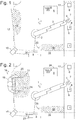
- Fig. 1 is a schematic plan view of an industrial robot 1 and its working environment.
- the robot 1 has a stationary base 2, one articulated arm 3 and an end effector 4 at the free end of the arm, but it should be kept in mind that the method which will be described subsequently is also applicable to more complex systems in which the robot is mobile and/or in which it comprises more than one arm and/or more than one end effector.
- the motion of the robot 1 is controlled by a processor unit 5, typically a microcomputer, in order to carry out a predefined manufacturing task, for example combining each of a series of first workpieces 6, supplied by a conveyor 7, with a second workpiece 8, taken from a crate 9.
- a processor unit 5 typically a microcomputer
- the processor unit 5 may comprise two functionally separate but cooperating processor units: A first processor unit for controlling the robot, and a second processor unit for sensor data evaluation. Both can be within the same electronics rack, but can also be set up apart from each other. Functionally both together make up the processor unit 5.
- the processor unit 5 is connected to a spatially resolving sensor 10 which is designed and positioned to monitor the vicinity of the robot 1.
- a spatially resolving sensor 10 which is designed and positioned to monitor the vicinity of the robot 1.
- the sensor 10 is represented as a single camera. In practice it may comprise several cameras viewing the vicinity of the robot 1 from different directions, so that no object can be hidden from all cameras at a time by the robot 1, and so that the processor unit 5 can determine coordinates of an object seen by more than one camera by triangulation.
- any other type of sensor capable of providing spatially resolved information on objects in the vicinity of the robot 1 can be used as or combined into the sensor 10, e.g. a radar device, one or more laser or microwave scanners, weight-sensitive tiles on the floor around base 2, etc.
- Fig. 1 the space in which the robot 1 is working is partially confined by walls or barriers 11. Part of these walls or barriers 11 is in the detection range of sensor 10.
- One of the walls 11 has a passage 12 through which a moving object might at any time enter the vicinity of the robot 1 and collide with it. While a contact between the object and the robot 1 may be desired and should not be prevented, it should be made sure that when such a contact occurs, the robot 1 is at rest and cannot damage the object. Therefore, at all times, the processor unit 5 defines a safety zone 13 which extends from the passage 12 into the vicinity and which it will not allow the robot 1 to enter.
- the dimension of the safety zone 13 is determined by the condition that whenever an object enters the vicinity through passage 12 with a reasonable speed, e.g. of a quickly walking human, it shall be possible to bring the robot to rest before the object and the robot 1 can touch each other.
- the size of the safety zone 13 may vary depending on the instantaneous speed of the robot. The faster the robot 1 moves, the longer is the time needed to bring it to a standstill, and the longer is the distance an intruding object would cover in that time; therefore the width of the safety zone 13 can be adapted to the robot speed.
- the direction of the robot movement can be taken into account, making the safety zone 13 larger when the robot 1 is approaching the passage 12, and making it narrower when the robot 1 is moving away from it.
- the detection range of the sensor 10 can be limited not only by walls 11 but also by objects such as e.g. an electronics rack 14 accommodating processor unit 5, which might be movable but are usually not moved while the robot 1 is operating.
- an electronics rack 14 accommodating processor unit 5 which might be movable but are usually not moved while the robot 1 is operating.
- a passage 15 between the rack 14 and the conveyor 7 which is hidden from the sensor 10 and from which a further safety zone 16 defined according to the same criteria as described above for safety zone 12 extends into the vicinity of the robot 1.
- the processor unit 5 may be provided with a geometrical model of the vicinity in which all passages by which a human might enter are specified.
- the system of Fig. 1 has at least one more passage, 17, namely the one by which first workpieces 6 enter the vicinity.
- a safety zone assigned to this passage 17 might be a nuisance for operation of the robot 1, since it might have to be considered when controlling the movement of the robot 1 between the crate 9 and the conveyor 7. Therefore, this passage 17 has no safety zone assigned to it.
- the lack of a safety zone here may be justified pragmatically by the assumption that no human will voluntarily sit on the conveyor and that therefore the possibility that an object qualifying for extended protection might approach the robot 1 through passage 17 can be neglected, or it may be justified technically by blocking access to an upstream portion of the conveyor 7, beyond passage 17, or by making passage 17 too small for a human to pass.
- the sensor 10 When the system is operating, the sensor 10 will detect any first workpiece 6 that enters the vicinity by passage 17, but as this passage 17 has no safety zone assigned to it, the workpieces 6 are automatically detected as what they are, i.e. as objects which do not have to be protected from contact with the robot but are there to be handled by it.
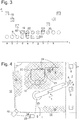
- the object 18 entering the vicinity by passage 12 is a person 19 carrying a crate 20.
- the processor unit 5 cannot be certain of the nature of the object 18 and must expect it to move unpredictably. Therefore, as a matter of precaution, it regards the object 18 as qualified for extended protection and therefore defines a safety zone 21 around said object 18 according to the same criteria as described above for safety zone 13. The object 18 will stay surrounded by this safety zone 21 while it moves in the vicinity of the robot 1 and e.g. replaces the old crate 9 by the new one 20, filled with fresh second workpieces 8.
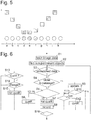
- Fig. 3 illustrates how the judgment of the processor unit 5 on the qualification of the various objects 18, 9 in the vicinity evolves in the course of this replacement.
- step a there are two symbols, a square one at a long distance d from the robot 1, representative of the object 18, and a round one, at a small distance, representative of crate 9.
- the symbol of object 18 is cross-hatched, indicative of its qualification for extended protection; the symbol of crate 9 is empty, since the crate 9 does not qualify, but rather, the workpieces 8 in it are there to be manipulated by the robot 1.
- the qualification statuses of object 18 and crate 9 remain unchanged in steps b and c, while the person 19 approaches crate 9.
- the processor unit 5 changes the status of the crate 9, indicated by cross-hatching of its symbol in Fig. 3 in step d.
- the safety zone 21 is extended to envelop also crate 9, as shown in Fig. 4 .
- the extended safety zone 21 prevents the robot 1 from fetching a new second workpiece from crate 9.
- the person 19 puts down the new crate 20, whereby the crate 20 and the person 19 become distinguishable as two objects by the sensor 10 and the processor unit 5. This is represented by distinct symbols for the crate 20 and for the person 19 appearing in step e.
- step f the person 19 takes up the old crate 9, represented by a new symbol 22 of a combined object formed of the person 19 and the crate 9, replacing that of crate 9.
- the combined object 21, i.e. the person 19 and the old crate 9 leave the vicinity, while the new crate 20 stays behind.
- One possible criterion for such a decision is the absence of motion. If no motion of an object is detected within a predetermined time span, the object can be assumed to be inanimate and therefore not to need a degree of protection which would prevent a contact with the robot 1 even if the object suddenly started to move.
- the duration of such a time span depends on the precision with which the sensor 10 is capable of detecting motion. If the sensor 10 is sensitive enough to detect micro-motion related to heartbeat or respiration, a duration of some seconds may be sufficient for a reliable judgment.
- Judgment might also be based on temperature. If the object to be judged is or comprises a human, then at least part of its surface should emanate infrared radiation. So, if the sensor 10 comprises a pyrometer, and the pyrometer detects no part of the surface of the object with a temperature that might fit a human body, then the object is most likely inanimate and can be judged not to qualify for extended protection.
- Another criterion which is easy to evaluate is the weight of the object; if it is noticeably different from that of a human, the object can be judged not to qualify.
- a disadvantage of this criterion is that the weight cannot be sensed remotely, so that the vicinity of the robot must be equipped at considerable cost with appropriate sensors, such as the weight-sensitive tiles mentioned above.
- the sensor 10 comprises a camera
- image processing techniques can be used to extract information on the shape and/or dimensions of the object from the data provided by the camera, and extended protection may be ruled out if these data allow to exclude the presence of a human, e.g. in case of the crate 19, because it is too small for a human to fit in.
- the processor unit 5 can have a user interface 23 where a user can inspect the objects which the processor unit 5 has found to qualify for extended protection, e.g. by having them highlighted in an image of the vicinity displayed on a screen, and, if necessary, change the status of an object.
- the crates 9, 20 carry tags 24 that can be read by the sensor 10 and that specify the nature of the object to which they are attached and/or some of its characteristics.
- a tag can be an optical tag, e.g. a QR tag, which can be read using the camera of sensor 10.
- it is a tag which communicates by radio, such as an RFID tag, a Bluetooth or NFC device, and the processor unit 5 has a radio interface 25 connected to it for communicating with the tags 24. In that case, when the tag 24 enters the range of radio interface 25, the processor unit 5 receives data from the tag 24, from which it can draw conclusions on characteristics detectable by sensor 10, of an object which may be about to enter or may already have entered the vicinity of the robot 1.
- These data may e.g. specify that the object carrying tag 24 is a crate, its size, and other characteristics.
- the processor unit 5 finds that these do not match object 18. Therefore, while the person 19 is moving in the vicinity of the robot 1 carrying the crate, data from the tag 24 will never induce the processor unit 5 to deny extended protection.
- the processor unit 5 will find the data from tag 24 to match this object, so that the crate 20 is found not to qualify for extended protection as soon as the distance between it and the person 19 is long enough, in step k of Fig. 3 .
- An object which does not qualify for extended protection can still have a safety zone, but the width of the safety zone can be substantially reduced; in case of the crate 20 such a safety zone may prevent the robot from touching the walls of the crate 19 while being small enough to allow the robot to reach in the crate 20 and take out workpieces 8 without violating the safety zone.
- a non-qualifying object may have no safety zone at all; in that case the robot 1 would be allowed to touch and handle it, e.g. to grab the crate 20 and to pull it from where the person 19 put it to a location closer to the conveyor 7.
- the diagram of Fig. 5 relates to a situation in which an object moves through the vicinity of the robot 1 without actually interacting physically with other objects therein, e.g. in which person 19 comes in through passage 12, works on the robot 1 and walks out again.
- the first steps of the diagram are similar to those of Fig. 3 ; on his way to the end effector 4 of robot 1, the person 19 passes within an arm's length of crate 9 and thereby makes it qualify for extended protection, too, in step d.
- the status of the crate 9 is reversed to not qualifying in step g.
- the robot 1 returns to normal operation after a certain delay.
- the qualifying status has been conferred to the crate 9 by the person 19 merely coming close, and if no contact between these person and the crate has occurred, so that the two objects have never become undistinguishable
- the status of the crate 9 can be returned no non-qualifying as soon as the person 19 starts to move away from it or, at latest, when the distance between the two objects 9, 19 increases above said arm's length or some other appropriately defined threshold, thus minimizing the delay with which normal operation is resumed.
- Fig. 6 is a flowchart of a control method of the processor unit 5 which is continuously re-iterated in order to achieve the above-described behaviour.
- step S1 the processor unit 5 fetches current data on the vicinity of the robot, e.g. an image or, if the sensor 10 comprises multiple cameras, a set of images. Based on a pre-defined geometrical model of the vicinity, it identifies the permanent objects which form this vicinity, such as the walls 11, the conveyor 7, the rack 14, and possibly also the robot 1 itself (S2). Any image details not accounted for by these objects must be related to non-permanent objects.
- step S3 If any of these objects was already present in a previous iteration of the method, data relating to it will have been recorded by the processor unit 5; if a non-permanent object exists which has moved since the previous iteration or which has newly entered the vicinity, it will be detected in step S3 since its position as derived from the current sensor data will not match any of the recorded position data.
- step S4 If such an object exists and its position is found in step S4 to be closer to a passage 12, 15 or 17 than to any recently recorded position, the object is judged to be new in the vicinity. If the passage was one of the passages 12, 15 that can be passed by a human (S5), the object is possibly human and is therefore judged to qualify for extended protection in step S6; else, if the entry point was passage 17, it is judged not to qualify in step S7. The entry point is included in the object data recorded in step S8.
- step S4 If in step S4 the object is found to be closer to a previously existing object than to a passage, then the object is regarded as being identical to or being a fragment of said previously existing object, and the protection status and the entry point of said previously existing object are copied to the present object (S9).
- the object 18 of Fig. 2 moves through the vicinity, it is always judged as qualifying for extended protection whereas the workpieces 6 moving on conveyor 7 do not. Due to the possibility of fragmentation, when the person 19 sets down crate 20 in the scenario of Fig. 4 and moves away from it, both become objects of their own and are judged to qualify for extended protection.
- Step S10 checks whether the copied status of the object is not qualifying and its entry point is one of passages 12, 15. If both conditions are met, a check is carried out in step S11 whether within an arm's length of the there is another object which does qualify, and if exists, the status of the object is changed to qualifying (12). This is what happened to crate 9 in step d of Fig. 3 .
- step S3 If a current data set is found in step S3 to be identical to a previously recorded one, it must belong to an object which hasn't moved since the previous iteration. If the status of the object is not qualifying (S13), nothing happens to it. Else the processing unit 5 examines (S14), using one or more of the criteria described above, whether the status may be changed, and changes it to non-qualifying (S15) if the criteria are met.
- Step S16 checks whether there is an object whose data have not yet been processed, and if there is, the method returns to step S3 to process another set of data; if there isn't, the iteration is finished.
Landscapes
- Engineering & Computer Science (AREA)
- Mechanical Engineering (AREA)
- General Engineering & Computer Science (AREA)
- Robotics (AREA)
- Radar, Positioning & Navigation (AREA)
- Remote Sensing (AREA)
- Manipulator (AREA)
Priority Applications (4)
| Application Number | Priority Date | Filing Date | Title |
|---|---|---|---|
| CN201880064581.1A CN111201115B (zh) | 2017-08-02 | 2018-07-25 | 机器人控制方法 |
| PCT/EP2018/070161 WO2019025255A1 (en) | 2017-08-02 | 2018-07-25 | ROBOT CONTROL METHOD |
| EP18742810.7A EP3661703A1 (de) | 2017-08-02 | 2018-07-25 | Robotersteuerungsverfahren |
| US16/777,918 US11511432B2 (en) | 2017-08-02 | 2020-01-31 | Robot control method |
Applications Claiming Priority (1)
| Application Number | Priority Date | Filing Date | Title |
|---|---|---|---|
| EP17184381 | 2017-08-02 |
Publications (1)
| Publication Number | Publication Date |
|---|---|
| EP3437804A1 true EP3437804A1 (de) | 2019-02-06 |
Family
ID=59522943
Family Applications (2)
| Application Number | Title | Priority Date | Filing Date |
|---|---|---|---|
| EP17194103.2A Withdrawn EP3437804A1 (de) | 2017-08-02 | 2017-09-29 | Robotersteuerungsverfahren |
| EP18742810.7A Pending EP3661703A1 (de) | 2017-08-02 | 2018-07-25 | Robotersteuerungsverfahren |
Family Applications After (1)
| Application Number | Title | Priority Date | Filing Date |
|---|---|---|---|
| EP18742810.7A Pending EP3661703A1 (de) | 2017-08-02 | 2018-07-25 | Robotersteuerungsverfahren |
Country Status (4)
| Country | Link |
|---|---|
| US (1) | US11511432B2 (de) |
| EP (2) | EP3437804A1 (de) |
| CN (1) | CN111201115B (de) |
| WO (1) | WO2019025255A1 (de) |
Cited By (5)
| Publication number | Priority date | Publication date | Assignee | Title |
|---|---|---|---|---|
| EP3941689A1 (de) * | 2019-03-18 | 2022-01-26 | MacGregor Norway AS | Mehrachsiger roboterarm |
| WO2022167076A1 (en) * | 2021-02-04 | 2022-08-11 | Abb Schweiz Ag | Method of controlling mechanical impedance of robot, control system and robot |
| EP4088887A1 (de) * | 2021-05-13 | 2022-11-16 | OMRON Corporation | Bereichseinstellungsvorrichtung, rack, steuerungssystem, bereichseinstellungsverfahren und programm |
| EP4400294A1 (de) * | 2023-01-12 | 2024-07-17 | Continental Reifen Deutschland GmbH | Unstetigförderer |
| CN120095285A (zh) * | 2025-04-22 | 2025-06-06 | 中国船舶集团有限公司第七一六研究所 | 一种大型船舶结构件电弧增材制造安全防控系统及方法 |
Families Citing this family (25)
| Publication number | Priority date | Publication date | Assignee | Title |
|---|---|---|---|---|
| US11396099B2 (en) | 2019-08-23 | 2022-07-26 | Veo Robotics, Inc. | Safe operation of machinery using potential occupancy envelopes |
| US11919173B2 (en) | 2019-08-23 | 2024-03-05 | Veo Robotics, Inc. | Motion planning and task execution using potential occupancy envelopes |
| US12097625B2 (en) | 2018-02-06 | 2024-09-24 | Veo Robotics, Inc. | Robot end-effector sensing and identification |
| US11830131B2 (en) | 2018-02-06 | 2023-11-28 | Veo Robotics, Inc. | Workpiece sensing for process management and orchestration |
| US12596346B2 (en) | 2018-08-30 | 2026-04-07 | Symbotic Llc | Systems and methods for information-assisted sensor registration |
| EP3843956B1 (de) | 2018-08-30 | 2025-12-31 | Veo Robotics, Inc. | Systemidentifikation der dynamik industrieller roboter für sicherheitskritische anwendungen |
| EP3844948B1 (de) | 2018-08-30 | 2023-11-01 | Veo Robotics, Inc. | Computersichtsystem mit tiefenerfassung |
| US12418638B2 (en) | 2018-08-30 | 2025-09-16 | Symbotic Llc | Calibration of depth-sensing computer vision systems |
| EP3844432B1 (de) | 2018-08-30 | 2025-06-04 | Veo Robotics, Inc. | Systeme und verfahren zur automatischen sensorregistrierung und -konfiguration |
| WO2020176473A1 (en) | 2019-02-27 | 2020-09-03 | Veo Robotics, Inc. | System architecture for safety applications |
| WO2020188137A1 (en) * | 2019-03-15 | 2020-09-24 | Eid Robotics Oy | A system and a method for forming a controlled safety area for a manipulator |
| US11504193B2 (en) | 2019-05-21 | 2022-11-22 | Verb Surgical Inc. | Proximity sensors for surgical robotic arm manipulation |
| US11278361B2 (en) | 2019-05-21 | 2022-03-22 | Verb Surgical Inc. | Sensors for touch-free control of surgical robotic systems |
| US12420419B2 (en) | 2019-08-23 | 2025-09-23 | Symbotic Llc | Motion planning and task execution using potential occupancy envelopes |
| US20220234209A1 (en) * | 2019-08-23 | 2022-07-28 | Ilya A. Kriveshko | Safe operation of machinery using potential occupancy envelopes |
| US11256241B1 (en) | 2019-09-12 | 2022-02-22 | Veo Robotics, Inc. | Optimized factory schedule and layout generation |
| EP4069472A4 (de) * | 2019-12-05 | 2024-03-20 | MAGNA Powertrain GmbH & Co KG | Verfahren und einrichtung für zaunlose robotik |
| JP7243603B2 (ja) * | 2019-12-09 | 2023-03-22 | トヨタ自動車株式会社 | 搬送ロボットシステム |
| CN119381314A (zh) * | 2020-03-31 | 2025-01-28 | 芝浦机械电子装置株式会社 | 基板处理装置以及基板处理方法 |
| KR102519131B1 (ko) * | 2021-04-02 | 2023-04-10 | 한국전자기술연구원 | 태그 기반 로봇 제어기의 작업 궤적 생성 방법 및 장치 |
| CN113219926A (zh) * | 2021-05-13 | 2021-08-06 | 中国计量大学 | 基于数字孪生系统的人机共融制造单元安全风险评估方法 |
| CN113400353B (zh) * | 2021-07-07 | 2024-02-02 | 西北工业大学 | 基于数字孪生的多指灵巧手状态监测方法、装置及设备 |
| CN114905520B (zh) * | 2022-06-28 | 2023-11-24 | 中国华能集团清洁能源技术研究院有限公司 | 双臂协作机器人安全限位方法、装置、设备及存储介质 |
| CN117556389A (zh) * | 2023-11-06 | 2024-02-13 | 深圳市汇川技术股份有限公司 | 一种基于安全区域的保护和配置方法、装置及设备 |
| DE102024123003A1 (de) * | 2024-08-12 | 2026-02-12 | Pilz Gmbh & Co. Kg | Vorrichtung zur sicheren Abwesenheitserkennung von Personen in einem Überwachungsbereich |
Citations (7)
| Publication number | Priority date | Publication date | Assignee | Title |
|---|---|---|---|---|
| US20080021597A1 (en) * | 2004-08-27 | 2008-01-24 | Abb Research Ltd. | Device And Method For Safeguarding A Machine-Controlled Handling Device |
| WO2010060475A1 (en) * | 2008-11-26 | 2010-06-03 | Abb Research Ltd. | Industrial robot |
| US7778776B2 (en) * | 2006-08-08 | 2010-08-17 | Panasonic Corporation | Obstacle avoidance method and obstacle-avoidable mobile apparatus |
| US20110025547A1 (en) | 2009-03-26 | 2011-02-03 | Tialinx, Inc. | Determination of hostile individuals armed with weapon, using respiration and heartbeat as well as spectral analysis at 60 ghz |
| US20140316261A1 (en) | 2013-04-18 | 2014-10-23 | California Institute Of Technology | Life Detecting Radars |
| US20150061880A1 (en) * | 2013-08-30 | 2015-03-05 | Joy Mm Delaware, Inc. | Proximity detection systems and methods |
| US20150158178A1 (en) * | 2012-07-10 | 2015-06-11 | Siemens Aktiengesellschaft | Robot arrangement and method for controlling a robot |
Family Cites Families (6)
| Publication number | Priority date | Publication date | Assignee | Title |
|---|---|---|---|---|
| US9032659B1 (en) * | 2011-03-08 | 2015-05-19 | Scott A. Duneman | Rotatable forearm/hand-guard assembly for a firearm |
| US10186130B2 (en) * | 2016-07-28 | 2019-01-22 | The Boeing Company | Using human motion sensors to detect movement when in the vicinity of hydraulic robots |
| CN110072673B (zh) * | 2016-10-20 | 2022-11-25 | 睿博天米以色列有限公司 | 跟踪人类的机器人及其方法 |
| JP6822069B2 (ja) * | 2016-11-01 | 2021-01-27 | オムロン株式会社 | 監視システム、監視装置、および監視方法 |
| US11097422B2 (en) * | 2017-02-07 | 2021-08-24 | Veo Robotics, Inc. | Safety-rated multi-cell workspace mapping and monitoring |
| EP3421189B1 (de) * | 2017-06-28 | 2019-05-22 | Sick AG | Verfahren zum überwachen einer maschine |
-
2017
- 2017-09-29 EP EP17194103.2A patent/EP3437804A1/de not_active Withdrawn
-
2018
- 2018-07-25 CN CN201880064581.1A patent/CN111201115B/zh active Active
- 2018-07-25 EP EP18742810.7A patent/EP3661703A1/de active Pending
- 2018-07-25 WO PCT/EP2018/070161 patent/WO2019025255A1/en not_active Ceased
-
2020
- 2020-01-31 US US16/777,918 patent/US11511432B2/en active Active
Patent Citations (7)
| Publication number | Priority date | Publication date | Assignee | Title |
|---|---|---|---|---|
| US20080021597A1 (en) * | 2004-08-27 | 2008-01-24 | Abb Research Ltd. | Device And Method For Safeguarding A Machine-Controlled Handling Device |
| US7778776B2 (en) * | 2006-08-08 | 2010-08-17 | Panasonic Corporation | Obstacle avoidance method and obstacle-avoidable mobile apparatus |
| WO2010060475A1 (en) * | 2008-11-26 | 2010-06-03 | Abb Research Ltd. | Industrial robot |
| US20110025547A1 (en) | 2009-03-26 | 2011-02-03 | Tialinx, Inc. | Determination of hostile individuals armed with weapon, using respiration and heartbeat as well as spectral analysis at 60 ghz |
| US20150158178A1 (en) * | 2012-07-10 | 2015-06-11 | Siemens Aktiengesellschaft | Robot arrangement and method for controlling a robot |
| US20140316261A1 (en) | 2013-04-18 | 2014-10-23 | California Institute Of Technology | Life Detecting Radars |
| US20150061880A1 (en) * | 2013-08-30 | 2015-03-05 | Joy Mm Delaware, Inc. | Proximity detection systems and methods |
Cited By (8)
| Publication number | Priority date | Publication date | Assignee | Title |
|---|---|---|---|---|
| EP3941689A1 (de) * | 2019-03-18 | 2022-01-26 | MacGregor Norway AS | Mehrachsiger roboterarm |
| WO2022167076A1 (en) * | 2021-02-04 | 2022-08-11 | Abb Schweiz Ag | Method of controlling mechanical impedance of robot, control system and robot |
| EP4088887A1 (de) * | 2021-05-13 | 2022-11-16 | OMRON Corporation | Bereichseinstellungsvorrichtung, rack, steuerungssystem, bereichseinstellungsverfahren und programm |
| JP2022175508A (ja) * | 2021-05-13 | 2022-11-25 | オムロン株式会社 | 領域設定装置、ラック、制御システム、領域設定方法及びプログラム |
| CN115421475A (zh) * | 2021-05-13 | 2022-12-02 | 欧姆龙株式会社 | 区域设定装置、机架、控制系统、区域设定方法以及存储有程序的记录介质 |
| US12459122B2 (en) | 2021-05-13 | 2025-11-04 | Omron Corporation | Area setting device, rack, control system, area setting method, and non-transitory computer readable medium storing program |
| EP4400294A1 (de) * | 2023-01-12 | 2024-07-17 | Continental Reifen Deutschland GmbH | Unstetigförderer |
| CN120095285A (zh) * | 2025-04-22 | 2025-06-06 | 中国船舶集团有限公司第七一六研究所 | 一种大型船舶结构件电弧增材制造安全防控系统及方法 |
Also Published As
| Publication number | Publication date |
|---|---|
| WO2019025255A1 (en) | 2019-02-07 |
| EP3661703A1 (de) | 2020-06-10 |
| US20200164516A1 (en) | 2020-05-28 |
| CN111201115A (zh) | 2020-05-26 |
| US11511432B2 (en) | 2022-11-29 |
| CN111201115B (zh) | 2023-04-04 |
Similar Documents
| Publication | Publication Date | Title |
|---|---|---|
| US11511432B2 (en) | Robot control method | |
| CN104428107B (zh) | 机器人布置和用于控制机器人的方法 | |
| CN111226178B (zh) | 监视设备、工业系统、用于监视的方法及计算机程序 | |
| CN101512452B (zh) | 基于摄像机监控具有移动机器部件的机器以防碰撞 | |
| CN104169630B (zh) | 用于使危险区域安全的方法和设备 | |
| KR102235513B1 (ko) | 적어도 부분적으로 자율적으로 움직이는, 이동식 의료용 유닛을 동작시키기 위한 방법, 및 이동식 의료용 유닛 | |
| JP6364747B2 (ja) | 監視装置および監視方法 | |
| EP2772336B1 (de) | Erkennungsbasierte, industrielle Automatisierungssteuerung mit Positions- und Ableitungsentscheidungsreferenz | |
| CN113840698B (zh) | 用于自动零售店环境的机器人补货和安全系统 | |
| EP2364243B1 (de) | Robotersicherheitssystem und verfahren | |
| CN108349078B (zh) | 操纵器系统的保护区调整 | |
| CN104057444B (zh) | 机器人系统及机器人系统的控制方法 | |
| CN108008663A (zh) | 监测系统、监测装置以及监测方法 | |
| US20190030716A1 (en) | Method and device for controlling a robot during co-activity | |
| US11370612B2 (en) | Transport system for products and method of removing a dropped product | |
| US20190001504A1 (en) | Method For Detecting A Collision Of A Robot Arm With An Object, And A Robot With A Robot Arm | |
| EP3569366B1 (de) | Verfahren und vorrichtung zur robotersteuerung | |
| CN108068140A (zh) | 用于作用到物件上的设备和方法 | |
| EP2772812B1 (de) | Erkennungsbasierte industrielle Automatisierungssteuerung mit Unterstützung von redundanter Systemeingabe | |
| KR20260010292A (ko) | Ai 기반 안전 지능화 로봇, 로봇의 제어 방법 및 이를 포함하는 시스템 | |
| US9193071B2 (en) | Control of a robot | |
| CN109716010A (zh) | 用于仓储系统的安全组件和仓储系统 | |
| CN118103176A (zh) | 处理工业机器人的安全的方法、控制系统和机器人系统 | |
| Bermuth et al. | KoARob: towards AI-based safety in human-robot-collaborations | |
| Makris | Dynamic Safety Zones in Human Robot Collaboration |
Legal Events
| Date | Code | Title | Description |
|---|---|---|---|
| PUAI | Public reference made under article 153(3) epc to a published international application that has entered the european phase |
Free format text: ORIGINAL CODE: 0009012 |
|
| AK | Designated contracting states |
Kind code of ref document: A1 Designated state(s): AL AT BE BG CH CY CZ DE DK EE ES FI FR GB GR HR HU IE IS IT LI LT LU LV MC MK MT NL NO PL PT RO RS SE SI SK SM TR |
|
| AX | Request for extension of the european patent |
Extension state: BA ME |
|
| STAA | Information on the status of an ep patent application or granted ep patent |
Free format text: STATUS: THE APPLICATION HAS BEEN WITHDRAWN |
|
| 18W | Application withdrawn |
Effective date: 20190724 |