EP3438385B1 - Serrure pour récipients transportables, tels que des malles, des valises, des caisses, des chariots ou analogues - Google Patents
Serrure pour récipients transportables, tels que des malles, des valises, des caisses, des chariots ou analogues Download PDFInfo
- Publication number
- EP3438385B1 EP3438385B1 EP18183973.9A EP18183973A EP3438385B1 EP 3438385 B1 EP3438385 B1 EP 3438385B1 EP 18183973 A EP18183973 A EP 18183973A EP 3438385 B1 EP3438385 B1 EP 3438385B1
- Authority
- EP
- European Patent Office
- Prior art keywords
- clamp
- flap
- lever
- lock
- shells
- Prior art date
- Legal status (The legal status is an assumption and is not a legal conclusion. Google has not performed a legal analysis and makes no representation as to the accuracy of the status listed.)
- Active
Links
Images


Classifications
-
- E—FIXED CONSTRUCTIONS
- E05—LOCKS; KEYS; WINDOW OR DOOR FITTINGS; SAFES
- E05B—LOCKS; ACCESSORIES THEREFOR; HANDCUFFS
- E05B65/00—Locks or fastenings for special use
- E05B65/52—Other locks for chests, boxes, trunks, baskets, travelling bags, or the like
-
- E—FIXED CONSTRUCTIONS
- E05—LOCKS; KEYS; WINDOW OR DOOR FITTINGS; SAFES
- E05B—LOCKS; ACCESSORIES THEREFOR; HANDCUFFS
- E05B65/00—Locks or fastenings for special use
- E05B65/52—Other locks for chests, boxes, trunks, baskets, travelling bags, or the like
- E05B65/5207—Other locks for chests, boxes, trunks, baskets, travelling bags, or the like characterised by bolt movement
- E05B65/5246—Other locks for chests, boxes, trunks, baskets, travelling bags, or the like characterised by bolt movement rotating
- E05B65/5269—Other locks for chests, boxes, trunks, baskets, travelling bags, or the like characterised by bolt movement rotating about an axis parallel to the surface on which the lock is mounted
- E05B65/5276—Other locks for chests, boxes, trunks, baskets, travelling bags, or the like characterised by bolt movement rotating about an axis parallel to the surface on which the lock is mounted parallel to the wing edge
-
- A—HUMAN NECESSITIES
- A45—HAND OR TRAVELLING ARTICLES
- A45C—PURSES; LUGGAGE; HAND CARRIED BAGS
- A45C13/00—Details; Accessories
- A45C13/10—Arrangement of fasteners
-
- E—FIXED CONSTRUCTIONS
- E05—LOCKS; KEYS; WINDOW OR DOOR FITTINGS; SAFES
- E05B—LOCKS; ACCESSORIES THEREFOR; HANDCUFFS
- E05B15/00—Other details of locks; Parts for engagement by bolts of fastening devices
Definitions
- the present invention relates to a lock for transportable containers, such as trunks, suitcases, cases, trolleys and the like.
- the present description also relates to a transportable container, such as trunks, suitcases, cases, trolleys and the like, that implements at least one above mentioned lock.
- the heterogeneous category of transportable containers available on the market includes trunks, cases, suitcases, trolleys (and others), that differ in shape, dimensions, materials, functions, as well as in intended use, type of transportable objects and reference customers.
- these containers are composed of two mutually articulated half-shells, made of high-strength polymeric material, which, when arranged in the closed configuration, isolate hermetically the compartment formed inside them, effectively preventing the entry of water, dust and contaminant agents in general.
- the compartment is maintained hermetically isolated from outside by a gasket extended along the edge of one of the half-shells, which is compressed elastically by the other half-shell when the container is closed again, preventing indeed the inflow of water, dust and other impurities.
- Each lock comprises a clamp, which is externally articulated to one of the two half-shells and forms a tooth engageable with a lip that protrudes from the other half-shell, so as to ensure indeed the mutual locking of the half-shells.
- the reopening of the container is entrusted to the action of the user, who must grip a terminal flap of the clamp in order to cause its rotation in the opposite direction with respect to the closure direction, forcing the disengagement of the tooth from the lip and allowing indeed the mutual movement of the half-shells.
- the locking ensured by the clamp is not completely reliable: in the event of impacts, in fact, the stresses transmitted can cause a further elastic deformation of the gasket and a slight movement of one half-shell with respect to the other. Sometimes the extent of this movement is in any case sufficient to make the tooth lose its grip on the lip, allowing the rotation of the clamp and the unintentional opening of the container. Clearly, this is an entirely unwanted event, which causes severe damage and inconvenience and must therefore be avoided.
- the aim of the present invention is to solve the problems described above, by providing a lock for transportable containers that ensure safe locking of the half-shells, contrasting effectively the accidental opening of the container in the case of impacts.
- an object of the invention is to provide a container provided with at least one lock capable of ensuring safe locking of the half-shells and of contrasting efficiently accidental opening in the event of impacts.
- Another object of the invention is to provide a lock that ensures an effective locking of the half-shells with a structurally simple solution that ensures in any case easy disengagement methods, without requiring significant efforts.
- Another object of the invention is to provide a lock and a container that ensure high reliability in operation.
- Another object of the present invention is to propose a lock that uses a technical and structural architecture that are alternative to those of locks of the known type.
- Another object of the invention is to provide a lock and a container that can be obtained easily starting from commonly commercially available elements and materials.
- Yet another object of the invention is to provide a lock and a container that have modest costs and are safe in application.
- the reference numeral 1 generally designates a lock for transportable containers 100, such as suitcases, trunks, cases, trolleys and the like.
- both the lock 1 and the container 100, provided with one or more locks 1, are the subject matter of the present description and of the protection claimed herein.
- any reference to the containers 100 is to be intended here as being extended to any type of product (suitcases, trunks, cases, trolleys or others) capable of accommodating objects and tools of various types, both for private use and for professional use.
- the container 100 comprises two half-shells 101 which can move between at least one closed configuration, in which they delimit an internal compartment for accommodating objects, and at least one open configuration, for free access to the compartment.
- the movement between the two configurations occurs by rotation of one of the half-shells 101 (the upper one, which acts as a lid) with respect to the other, wherein this rotation is made possible by one or more hinges installed on the rear walls of the half-shells 101.
- the container 100 for mainly professional use, is a kind of rigid trunk, made of polymeric material with high impact strength and provided with suitable solutions that ensure complete tightness and therefore the capacity to prevent the entry of water, humidity, dust and contaminating agents in general.
- hermetic tightness can be ensured by a gasket interposed between the half-shells 101 and normally compressed by them in an elastic manner in the closed configuration.
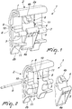
- the lock 1 comprises first of all a clamp 2, which can be articulated to one of the half-shells 101 (to the upper one in the accompanying figures), substantially with one first end portion 2a thereof.
- the clamp 2 is provided with at least one protruding tooth 3, which can engage a lip 102 which protrudes from the other half-shell 101 (the lower one in the accompanying figures) in a position for locking, by hindrance, the half-shells 101, when indeed said half-shells 101 are in the closed configuration.
- the lock 1 comprises moreover a lever 4 which is articulated to the clamp 2: the lever 4 is provided with at least one protruding hook 5, which is kept elastically engaged with the lip 102 ( Figure 5 ) when the clamp 2 is in the locking position.
- the lip 102 together with the adjacent wall of the container 100, forms a groove 103: according to methods that will be described hereinafter (for one possible embodiment), as long as the clamp 2 is in the locking position, the hook 5 of the lever 4 is kept inserted in the groove 103.
- the lever 4 has a first terminal flap 4a which substantially faces and is proximate to, (at least) in the locking position, a second end portion 2b of the clamp 2, which is opposite with respect to the first end portion 2a.
- a traction applied to the first flap 4a thus causes the disengagement of the hook 5 from the lip 102 and, by virtue of this close arrangement (which is evident for example in Figure 5 ), also the rotational actuation of the clamp 2, so as to disengage also the tooth 3 from said lip 102.
- the lever 4 is moved, in order to disengage the hook 5, its first flap 4a rests on the second end portion 2b of the clamp 2 ( Figure 6 ): by continuing the traction on the first flap 4a, the rotation of the clamp 2, actuated by the lever 4, is caused.
- the lever 4 prevents any accidental movement of said clamp 2 and therefore the unwanted opening of the container 100 following impacts.
- the opening of the container 100 (the release of the lock 1) is achieved in a completely practical and easy way by simply pulling toward oneself the lever 4, thus causing initially the disengagement of the hook 5 from the lip 102 and, after a small rotation, also the disengagement of the tooth 3 (rotationally actuated, with the entire clamp 2, by the lever 4).
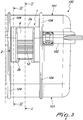
- the clamp 2 comprises a substantially plate-like shell 6 having a rectangular shape (as can be seen clearly from Figure 3 , for example).
- the shell 6 is bent at a perimetric edge, which forms the first end portion 2a and is crossed by a channel 7 for the insertion of a first pivot, for the articulation of the clamp 2 to the corresponding half-shell 101.
- the first pivot can be provided with the lock 1 or not, and for example can be inserted not only in the channel 7 but also in ribs 104 that protrude eternally from the half-shells 101, as indeed in the solution of the accompanying figures.
- the shell 6 has a recess 8 for the rotatable accommodation of the lever 4; when the lock 1 is mounted on the container 100, the shell 6 conceals from view the lever 4, which is indeed accommodated in the recess 8, thus protecting it from shocks and impacts.
- the first flap 4a (and the lever 4) is maintained in any case accessible from outside (in order to be able to open the container 100), since the recess 8 is open on the opposite side with respect to the cited perimetric edge (where indeed the first flap 4a is facing).
- the first flap 4a is according to the invention substantially aligned with the second end portion 2b of the clamp 2 (it is at the same vertical level), at least in the locking position.
- the lever 4 is articulated to the clamp 2 at a second pivot 9: the second pivot 9 is arranged parallel to the channel 7 (and therefore to the first pivot already mentioned) and is inserted in respective aligned seats 10, which are formed along the sides of the recess 8, which are constituted in turn by corresponding shaped crests 11 of the shell 6.
- the recess 8 is thus delimited on the bottom by the shell 6 itself, on two sides by the crests 11 and, on another side, by the folded perimetric edge of the shell 6 itself, while on the opposite side with respect to the perimetric edge it is open, in order to allow access to the lever 4.
- the shell 6 therefore conceals almost completely from view the lever 4, protecting it from shocks and impacts, which could otherwise cause the accidental disengagement of the lock 1. Only a deliberate action on the first flap 4a can allow the opening of the container 100.
- each crest 11 has a respective tooth 3; moreover, the (two) teeth 3 and the hook 5 are arranged substantially side by side, at least in the locking position.
- the lever 4 has, opposite with respect to the first terminal flap 4a, a second elastically deformable terminal flap 4b.
- the second terminal flap 4b by virtue of a convenient choice of the dimensions and of its spatial arrangement, is configured to deform elastically at the locking position (as shown in Figure 5 ).
- the second terminal flap 4b is substantially constituted by a curved protrusion which is directed in the opposite direction with respect to the clamp 2. It is not excluded, however, to resort to different embodiments for the second terminal flap 4b, which are in any case within the protective scope claimed herein. For example, it is not excluded to arrange a spring or a body made of elastomeric material on the lever 4, configured to press on the corresponding half-shell 101 in the locking position, thus being deformed elastically in the same way as the protrusion of the accompanying figures.
- the external face of the shell 6, opposite the crests 11, has at least one knurled area 12, in order to allow the user an easier grip.
- the terminal portion of the crests 11, which is opposite the first end portion 2a, has a rounded profile (as shown clearly by Figures 1, 2 and 4 , for example), for easier grip.
- the lock 1 can comprise a device for selectively enabling rotation by traction of the lever 4.
- the traction of the lever 4 is the one that allows disengagement of the hook 5 first and then of the teeth 3, for the rotation of the clamp 2 and thus the movement of one half-shell 101 with respect to the other. Therefore, the device can be activated/deactivated indeed in order to allow/prevent the movement of the lever 4 and the rotational actuation of the clamp 2.
- the device can be a body that is mounted so as to be normally in interference with the rotation of the lever 4 and configured so that it can be brought reversibly to an enabling condition, in which it does not hinder the trajectory of the lever 4 and thus does not resist its motion.
- Enabling can be provided for example by turning a key (which indeed moves the above mentioned body), so as to allow only the designed user (who has the key) to act on the lock 1 to open the container 100.
- the device thus acts as a kind of padlock or in any case as a further safety, giving an interesting additional particularity to the lock 1 according to the invention.
- a container 100 of the type of trunks, suitcases, cases, trolleys and the like, also is the subject matter of the present description (and of the protection claimed herein).
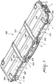
- said container 100 comprises two half-shells 101, which can move between at least one closed configuration, in which they delimit an internal compartment for accommodating objects (and in which the container 100 of Figure 7 is shown), and at least one open configuration, for free access to the compartment.
- At least one of the half-shells 101 has a protruding lip 102.
- This container 100 thus comprises at least one lock 1 having the specifications presented in the previous paragraphs (and, particularly, at least a lever 4 that is kept engaged with the lip 102, preventing accidental openings, and can rotationally actuate the clamp 2, for the disengagement of said lock 1).
- the container 100 can be provided with any number of locks 1 according to the invention (optionally also in addition to locks of another type), without abandoning the protective scope claimed herein.
- the user can lock them by acting on the locks 1, taking care to rotate (anticlockwise, in the example of the figures) the clamp 2 of each one of them up to the locking position, in which, as shown, each tooth 3 engages the lip 102, preventing by hindrance the subsequent rotation of the half-shell 101 that is located upward with respect to the other.
- the clamp 2 When the clamp 2 moves to the locking position, it actuates the lever 4 until it causes the engagement of its hook 5 with the lip 102: the hook 5 is retained in the groove 103 by the coupling reaction generated, on the opposite side, by the elastic deformation of the second terminal flap 4b of said lever 4, pressed against the upper half-shell 101.
- any traction applied only to the lever 2 causes the hook 5 to insert itself further in the groove 103, thus opposing even more forcefully the disengagement of the lock 1 and vice versa causing a stronger clamping.
- the lock 1 according to the invention ensures therefore a safe and effective locking of the half-shells 101, contrasting effectively accidental opening in case of impacts.
- the unlocking methods are particularly easy and ergonomic, requiring minimal effort: the user simply has to pull the lever 4a toward himself, using only one or in any case a small number of fingers, to be inserted under the first flap 4a, in order to obtain the disengagement of the hook 5 first and then, by actuation of the clamp 2, of the teeth 3, thus allowing the rotation of said clamp 2 and therefore the movement of one half-shell 101 with respect to the other.
- the selective enabling device allows to add a further function to the lock 1, making it actuatable only by the designated user.
- the materials used, as well as the dimensions, may be any according to the requirements and the state of the art.
Landscapes
- Purses, Travelling Bags, Baskets, Or Suitcases (AREA)
Claims (10)
- Serrure (1) destinée à des contenants transportables, tels que des malles, des valises, des coffres, des chariots et similaires, les contenants (100) comprenant deux demi-enveloppes (101) mobiles entre au moins une configuration fermée, dans laquelle elles délimitent un compartiment intérieur destiné à recevoir des objets, et au moins une configuration ouverte, permettant d'accéder librement au compartiment, et comprenant :- une bride (2), qui peut être articulée par rapport à l'une des demi-enveloppes (101) sensiblement avec une première partie extrémité (2a) de celle-ci, et dotée d'une dent saillante au moins (3), qui peut venir en prise avec une lèvre (102) qui fait saillie à partir de l'autre des demi-enveloppes (101) dans une position de verrouillage, par blocage, des demi-enveloppes (101) agencées dans la configuration fermée,- un levier (4), qui est articulé par rapport à ladite bride (2), et qui est doté d'un crochet saillant (5) au moins, qui est maintenu en prise de manière élastique avec la lèvre (102) lorsque ladite bride (2) se trouve dans ladite position de verrouillage,ledit levier (4) étant doté d'un premier rabat terminal (4a) qui, dans ladite position de verrouillage, fait sensiblement face et est proximal à une seconde partie extrémité (2b) de ladite bride (2), qui est opposée à ladite première partie (2a), une traction appliquée audit premier rabat (4a) provoquant la mise hors de prise dudit crochet (5) de la lèvre (102) et l'actionnement en rotation de ladite bride (2) pour mettre ladite dent (3) hors de prise de la lèvre (102),
ladite serrure (1) étant caractérisée en ce que, au moins dans ladite position de verrouillage, ledit premier rabat (4a) est sensiblement aligné avec ladite seconde partie extrémité (2b) de ladite bride (2), afin d'être sensiblement au même niveau vertical que ladite seconde partie extrémité (2b) de ladite bride (2), la direction verticale correspondant sensiblement à la direction qui joint les deux parties extrémités (2a, 2b) de la bride (2), afin de pouvoir actionner facilement ledit premier rabat (4a), en maintenant dans tous les cas ledit premier rabat (4a) protégé par ladite seconde partie extrémité (2b) de ladite bride (2), vis-à-vis de chocs et d'impacts accidentels. - Serrure selon la revendication 1, caractérisée en ce que ladite bride (2) comprend une enveloppe sensiblement similaire à une plaque (6) qui présente une forme rectangulaire, qui est pliée au niveau d'un bord périmétrique, en formant ladite première partie extrémité (2a), et qui est traversée par un canal (7) destiné à l'insertion d'un premier pivot, destiné à l'articulation de ladite bride (2) par rapport à la demi-enveloppe correspondante (101), ladite enveloppe (6) étant dotée d'un renfoncement (8) destiné à recevoir en rotation ledit levier (4), qui est ouvert du côté opposé par rapport audit bord périmétrique pour accéder audit premier rabat (4a), qui est sensiblement aligné avec ladite seconde partie extrémité (2b) de ladite bride (2), au moins dans ladite position de verrouillage.
- Serrure selon la revendication 2, caractérisée en ce que ledit levier (4) est articulé par rapport à ladite bride (2) au niveau d'un second pivot (9), qui est parallèle audit canal (7) et qui est inséré dans les sièges alignés respectifs (10) formés le long des côtés dudit renfoncement (8), qui sont constitués par des crêtes de formes correspondantes (11) de ladite enveloppe (6).
- Serrure selon la revendication 3, caractérisée en ce que chacune desdites crêtes (11) est dotée d'une dite dent respective (3), lesdites dents (3) et ledit crochet (5) se faisant sensiblement face, au moins dans ladite position de verrouillage.
- Serrure selon l'une quelconque des revendications précédentes, caractérisée en ce que ledit levier (4) présente, sur le côté opposé audit premier rabat terminal (4a), un second rabat terminal déformable élastiquement (4b), qui est configuré pour se déformer élastiquement au niveau de ladite position de verrouillage, la réaction d'accouplement générée par ledit second rabat (4b) dans ladite position de verrouillage maintenant ledit crochet (5) en prise avec la lèvre (102).
- Serrure selon la revendication 5, caractérisée en ce que ledit second rabat terminal (4b) est constitué sensiblement par une saillie incurvée qui est dirigée dans la direction opposée à ladite bride (2).
- Serrure selon l'une quelconque des revendications précédentes, caractérisée en ce que la face extérieure de ladite enveloppe (6), qui se situe à l'opposé desdites crêtes (11), présente au moins une zone moletée (12) pour une préhension plus facile.
- Serrure selon l'une quelconque des revendications précédentes, caractérisée en ce que la partie terminale desdites crêtes (11), qui se situe à l'opposé de ladite première partie extrémité (2a), présente un profil arrondi pour une préhension plus facile.
- Serrure selon l'une quelconque des revendications précédentes, caractérisée en ce qu'elle comprend un dispositif destiné à permettre sélectivement une rotation suite à une traction dudit levier (4), qui peut être activé / désactivé afin de permettre / d'empêcher le déplacement dudit levier (4) et la traction en rotation de ladite bride (2).
- Contenant transportable, tel qu'une malle, une valise, un coffre, un chariot et similaire, comprenant deux demi-enveloppes (101) mobiles entre au moins une configuration fermée, dans laquelle elles délimitent un compartiment intérieur destiné à recevoir des objets, et au moins une configuration ouverte, permettant d'accéder librement au compartiment, l'une au moins desdites demi-enveloppes (101) présentant une lèvre saillante (102), caractérisé en ce qu'il comprend au moins une serrure (1) selon l'une quelconque des revendications précédentes.
Applications Claiming Priority (1)
| Application Number | Priority Date | Filing Date | Title |
|---|---|---|---|
| IT102017000088144A IT201700088144A1 (it) | 2017-08-01 | 2017-08-01 | Serratura per contenitori trasportabili, del tipo di bauli, valigie, casse, trolley e simili |
Publications (2)
| Publication Number | Publication Date |
|---|---|
| EP3438385A1 EP3438385A1 (fr) | 2019-02-06 |
| EP3438385B1 true EP3438385B1 (fr) | 2020-06-17 |
Family
ID=60570144
Family Applications (1)
| Application Number | Title | Priority Date | Filing Date |
|---|---|---|---|
| EP18183973.9A Active EP3438385B1 (fr) | 2017-08-01 | 2018-07-17 | Serrure pour récipients transportables, tels que des malles, des valises, des caisses, des chariots ou analogues |
Country Status (3)
| Country | Link |
|---|---|
| EP (1) | EP3438385B1 (fr) |
| CN (1) | CN109322561A (fr) |
| IT (1) | IT201700088144A1 (fr) |
Cited By (2)
| Publication number | Priority date | Publication date | Assignee | Title |
|---|---|---|---|---|
| USD1028505S1 (en) | 2022-03-11 | 2024-05-28 | Magpul Industries Corp. | Long gun case |
| US12259213B2 (en) | 2022-03-11 | 2025-03-25 | Magpul Industries, Corp. | Firearm case with locking latches |
Families Citing this family (10)
| Publication number | Priority date | Publication date | Assignee | Title |
|---|---|---|---|---|
| FR3106476B1 (fr) * | 2020-01-24 | 2022-02-18 | Hermes Sellier | Article de maroquinerie du type bagage |
| US12275559B2 (en) | 2021-10-15 | 2025-04-15 | Makita U.S.A., Inc. | Modular storage system with storage box connectivity and internal storage and lid features |
| USD1093902S1 (en) | 2022-03-11 | 2025-09-23 | Magupl Industries Corp. | Organizing grid for storage case |
| USD1100495S1 (en) | 2022-03-11 | 2025-11-04 | Magpul Industries Corp. | Long gun case |
| CN115195324B (zh) * | 2022-05-12 | 2024-07-30 | 得力集团有限公司 | 一种文件夹的扣合结构及文件夹 |
| USD1059838S1 (en) | 2022-09-08 | 2025-02-04 | Magpul Industries Corp. | Organizing grid for storage case |
| USD1099528S1 (en) | 2022-09-08 | 2025-10-28 | Magpul Industries Corp. | Organizing grid for storage case |
| USD1059829S1 (en) | 2022-10-14 | 2025-02-04 | Makita U.S.A., Inc. | Storage box |
| CN119018481A (zh) * | 2023-05-26 | 2024-11-26 | 宁波美琪工具有限公司 | 储物箱用锁扣机构及储物箱 |
| USD1084666S1 (en) | 2023-10-18 | 2025-07-22 | Magpul Industries Corp. | Organizing grid for storage case |
Family Cites Families (8)
| Publication number | Priority date | Publication date | Assignee | Title |
|---|---|---|---|---|
| TW322421B (fr) * | 1994-07-15 | 1997-12-11 | Samsonite Corp | |
| US7837053B2 (en) * | 2000-10-12 | 2010-11-23 | Arnett Jeffrey D | Shock-resistant and environmentally sealed container |
| US20050217324A1 (en) * | 2004-04-06 | 2005-10-06 | Royal Lock Corporation | Lock with a linear movement hook resulting from rotatable movement of a control knob |
| US7540364B2 (en) * | 2004-09-01 | 2009-06-02 | Skb Corporation | Trigger latch assembly |
| US20110132046A1 (en) * | 2008-08-29 | 2011-06-09 | Massimo Tonelli | Lock, particularly for suitcases, trunks and the like |
| US8328247B2 (en) * | 2009-09-18 | 2012-12-11 | G.T. Line S.R.L. | Lock, particularly for suitcases, trunks and the like |
| CN202718476U (zh) * | 2012-08-03 | 2013-02-06 | 东莞市怡丰锁业有限公司 | 一种箱包复合密码锁 |
| RU2649259C2 (ru) * | 2013-12-10 | 2018-03-30 | Дж. Ти. ЛАЙН С.Р.Л. | Узел блокирования для переносных контейнеров и соответствующий контейнер |
-
2017
- 2017-08-01 IT IT102017000088144A patent/IT201700088144A1/it unknown
-
2018
- 2018-07-17 EP EP18183973.9A patent/EP3438385B1/fr active Active
- 2018-08-01 CN CN201810864619.5A patent/CN109322561A/zh active Pending
Non-Patent Citations (1)
| Title |
|---|
| None * |
Cited By (2)
| Publication number | Priority date | Publication date | Assignee | Title |
|---|---|---|---|---|
| USD1028505S1 (en) | 2022-03-11 | 2024-05-28 | Magpul Industries Corp. | Long gun case |
| US12259213B2 (en) | 2022-03-11 | 2025-03-25 | Magpul Industries, Corp. | Firearm case with locking latches |
Also Published As
| Publication number | Publication date |
|---|---|
| EP3438385A1 (fr) | 2019-02-06 |
| CN109322561A (zh) | 2019-02-12 |
| IT201700088144A1 (it) | 2019-02-01 |
Similar Documents
| Publication | Publication Date | Title |
|---|---|---|
| EP3438385A1 (fr) | Serrure pour récipients transportables, tels que des malles, des valises, des caisses, des chariots ou analogues | |
| TWI915617B (zh) | 具有基座、蓋及鎖閂之槍支鎖定盒 | |
| EP2315895B1 (fr) | Serrure, en particulier pour valises, malles et analogues | |
| EP1080656B1 (fr) | Fermoir pour sacs, valises et coffrets similaires | |
| ES2541013T3 (es) | Sistema integrado para la apertura y el cierre de una maleta para motocicletas y para el enganche y la liberación de dicha maleta con respecto a la motocicleta | |
| US20200196725A1 (en) | Portable container | |
| US7370891B1 (en) | Latching mechanism with trigger actuator | |
| MX2012005089A (es) | Caja fuerte con mecanismo de cierre dual. | |
| CN1497119A (zh) | 保险箱用的带扣可锁闩件 | |
| US8037723B2 (en) | Theft prevention device | |
| US10794092B2 (en) | Lock box | |
| KR200468325Y1 (ko) | 가방용 지퍼 잠금장치 | |
| EP2668462B1 (fr) | Boîtier permettant de transporter des pistolets en toute sécurité comprenant un étui associé | |
| JPH08110152A (ja) | コンテナのヒンジ装置 | |
| EP2511457B1 (fr) | Dispositif de verrouillage, en particulier pour récipients de type valises, malles et analogues | |
| KR101889302B1 (ko) | 밀폐용기 | |
| TWI600821B (zh) | 掛鎖上鎖式平面把手 | |
| KR101095230B1 (ko) | 러기지 박스용 커버의 잠금장치 | |
| KR20140100014A (ko) | 개폐 여부를 확인할 수 있는 제품 케이스 | |
| EP4706446A1 (fr) | Ensemble de transport et de fermeture de boîte amélioré | |
| KR100566658B1 (ko) | 사물함 | |
| KR200271104Y1 (ko) | 창문자동잠금장치의 구조 | |
| JP2000226061A (ja) | 蓋付き収納容器のロック装置 | |
| AU2025205369A1 (en) | Improved box closure and transport assembly | |
| JP2004300889A (ja) | ロック装置 |
Legal Events
| Date | Code | Title | Description |
|---|---|---|---|
| PUAI | Public reference made under article 153(3) epc to a published international application that has entered the european phase |
Free format text: ORIGINAL CODE: 0009012 |
|
| STAA | Information on the status of an ep patent application or granted ep patent |
Free format text: STATUS: THE APPLICATION HAS BEEN PUBLISHED |
|
| AK | Designated contracting states |
Kind code of ref document: A1 Designated state(s): AL AT BE BG CH CY CZ DE DK EE ES FI FR GB GR HR HU IE IS IT LI LT LU LV MC MK MT NL NO PL PT RO RS SE SI SK SM TR |
|
| AX | Request for extension of the european patent |
Extension state: BA ME |
|
| STAA | Information on the status of an ep patent application or granted ep patent |
Free format text: STATUS: REQUEST FOR EXAMINATION WAS MADE |
|
| 17P | Request for examination filed |
Effective date: 20190719 |
|
| RBV | Designated contracting states (corrected) |
Designated state(s): AL AT BE BG CH CY CZ DE DK EE ES FI FR GB GR HR HU IE IS IT LI LT LU LV MC MK MT NL NO PL PT RO RS SE SI SK SM TR |
|
| GRAP | Despatch of communication of intention to grant a patent |
Free format text: ORIGINAL CODE: EPIDOSNIGR1 |
|
| STAA | Information on the status of an ep patent application or granted ep patent |
Free format text: STATUS: GRANT OF PATENT IS INTENDED |
|
| INTG | Intention to grant announced |
Effective date: 20200102 |
|
| GRAS | Grant fee paid |
Free format text: ORIGINAL CODE: EPIDOSNIGR3 |
|
| GRAA | (expected) grant |
Free format text: ORIGINAL CODE: 0009210 |
|
| STAA | Information on the status of an ep patent application or granted ep patent |
Free format text: STATUS: THE PATENT HAS BEEN GRANTED |
|
| AK | Designated contracting states |
Kind code of ref document: B1 Designated state(s): AL AT BE BG CH CY CZ DE DK EE ES FI FR GB GR HR HU IE IS IT LI LT LU LV MC MK MT NL NO PL PT RO RS SE SI SK SM TR |
|
| REG | Reference to a national code |
Ref country code: GB Ref legal event code: FG4D |
|
| REG | Reference to a national code |
Ref country code: CH Ref legal event code: EP |
|
| REG | Reference to a national code |
Ref country code: DE Ref legal event code: R096 Ref document number: 602018005304 Country of ref document: DE |
|
| REG | Reference to a national code |
Ref country code: IE Ref legal event code: FG4D |
|
| REG | Reference to a national code |
Ref country code: AT Ref legal event code: REF Ref document number: 1281478 Country of ref document: AT Kind code of ref document: T Effective date: 20200715 |
|
| PG25 | Lapsed in a contracting state [announced via postgrant information from national office to epo] |
Ref country code: SE Free format text: LAPSE BECAUSE OF FAILURE TO SUBMIT A TRANSLATION OF THE DESCRIPTION OR TO PAY THE FEE WITHIN THE PRESCRIBED TIME-LIMIT Effective date: 20200617 Ref country code: NO Free format text: LAPSE BECAUSE OF FAILURE TO SUBMIT A TRANSLATION OF THE DESCRIPTION OR TO PAY THE FEE WITHIN THE PRESCRIBED TIME-LIMIT Effective date: 20200917 Ref country code: FI Free format text: LAPSE BECAUSE OF FAILURE TO SUBMIT A TRANSLATION OF THE DESCRIPTION OR TO PAY THE FEE WITHIN THE PRESCRIBED TIME-LIMIT Effective date: 20200617 Ref country code: LT Free format text: LAPSE BECAUSE OF FAILURE TO SUBMIT A TRANSLATION OF THE DESCRIPTION OR TO PAY THE FEE WITHIN THE PRESCRIBED TIME-LIMIT Effective date: 20200617 Ref country code: GR Free format text: LAPSE BECAUSE OF FAILURE TO SUBMIT A TRANSLATION OF THE DESCRIPTION OR TO PAY THE FEE WITHIN THE PRESCRIBED TIME-LIMIT Effective date: 20200918 |
|
| REG | Reference to a national code |
Ref country code: LT Ref legal event code: MG4D |
|
| REG | Reference to a national code |
Ref country code: NL Ref legal event code: MP Effective date: 20200617 |
|
| PG25 | Lapsed in a contracting state [announced via postgrant information from national office to epo] |
Ref country code: BG Free format text: LAPSE BECAUSE OF FAILURE TO SUBMIT A TRANSLATION OF THE DESCRIPTION OR TO PAY THE FEE WITHIN THE PRESCRIBED TIME-LIMIT Effective date: 20200917 Ref country code: LV Free format text: LAPSE BECAUSE OF FAILURE TO SUBMIT A TRANSLATION OF THE DESCRIPTION OR TO PAY THE FEE WITHIN THE PRESCRIBED TIME-LIMIT Effective date: 20200617 Ref country code: RS Free format text: LAPSE BECAUSE OF FAILURE TO SUBMIT A TRANSLATION OF THE DESCRIPTION OR TO PAY THE FEE WITHIN THE PRESCRIBED TIME-LIMIT Effective date: 20200617 Ref country code: HR Free format text: LAPSE BECAUSE OF FAILURE TO SUBMIT A TRANSLATION OF THE DESCRIPTION OR TO PAY THE FEE WITHIN THE PRESCRIBED TIME-LIMIT Effective date: 20200617 |
|
| REG | Reference to a national code |
Ref country code: AT Ref legal event code: MK05 Ref document number: 1281478 Country of ref document: AT Kind code of ref document: T Effective date: 20200617 |
|
| PG25 | Lapsed in a contracting state [announced via postgrant information from national office to epo] |
Ref country code: AL Free format text: LAPSE BECAUSE OF FAILURE TO SUBMIT A TRANSLATION OF THE DESCRIPTION OR TO PAY THE FEE WITHIN THE PRESCRIBED TIME-LIMIT Effective date: 20200617 Ref country code: NL Free format text: LAPSE BECAUSE OF FAILURE TO SUBMIT A TRANSLATION OF THE DESCRIPTION OR TO PAY THE FEE WITHIN THE PRESCRIBED TIME-LIMIT Effective date: 20200617 |
|
| PG25 | Lapsed in a contracting state [announced via postgrant information from national office to epo] |
Ref country code: EE Free format text: LAPSE BECAUSE OF FAILURE TO SUBMIT A TRANSLATION OF THE DESCRIPTION OR TO PAY THE FEE WITHIN THE PRESCRIBED TIME-LIMIT Effective date: 20200617 Ref country code: SM Free format text: LAPSE BECAUSE OF FAILURE TO SUBMIT A TRANSLATION OF THE DESCRIPTION OR TO PAY THE FEE WITHIN THE PRESCRIBED TIME-LIMIT Effective date: 20200617 Ref country code: AT Free format text: LAPSE BECAUSE OF FAILURE TO SUBMIT A TRANSLATION OF THE DESCRIPTION OR TO PAY THE FEE WITHIN THE PRESCRIBED TIME-LIMIT Effective date: 20200617 Ref country code: PT Free format text: LAPSE BECAUSE OF FAILURE TO SUBMIT A TRANSLATION OF THE DESCRIPTION OR TO PAY THE FEE WITHIN THE PRESCRIBED TIME-LIMIT Effective date: 20201019 Ref country code: RO Free format text: LAPSE BECAUSE OF FAILURE TO SUBMIT A TRANSLATION OF THE DESCRIPTION OR TO PAY THE FEE WITHIN THE PRESCRIBED TIME-LIMIT Effective date: 20200617 Ref country code: CZ Free format text: LAPSE BECAUSE OF FAILURE TO SUBMIT A TRANSLATION OF THE DESCRIPTION OR TO PAY THE FEE WITHIN THE PRESCRIBED TIME-LIMIT Effective date: 20200617 Ref country code: ES Free format text: LAPSE BECAUSE OF FAILURE TO SUBMIT A TRANSLATION OF THE DESCRIPTION OR TO PAY THE FEE WITHIN THE PRESCRIBED TIME-LIMIT Effective date: 20200617 |
|
| PG25 | Lapsed in a contracting state [announced via postgrant information from national office to epo] |
Ref country code: PL Free format text: LAPSE BECAUSE OF FAILURE TO SUBMIT A TRANSLATION OF THE DESCRIPTION OR TO PAY THE FEE WITHIN THE PRESCRIBED TIME-LIMIT Effective date: 20200617 Ref country code: SK Free format text: LAPSE BECAUSE OF FAILURE TO SUBMIT A TRANSLATION OF THE DESCRIPTION OR TO PAY THE FEE WITHIN THE PRESCRIBED TIME-LIMIT Effective date: 20200617 Ref country code: IS Free format text: LAPSE BECAUSE OF FAILURE TO SUBMIT A TRANSLATION OF THE DESCRIPTION OR TO PAY THE FEE WITHIN THE PRESCRIBED TIME-LIMIT Effective date: 20201017 |
|
| REG | Reference to a national code |
Ref country code: DE Ref legal event code: R097 Ref document number: 602018005304 Country of ref document: DE |
|
| PG25 | Lapsed in a contracting state [announced via postgrant information from national office to epo] |
Ref country code: MC Free format text: LAPSE BECAUSE OF FAILURE TO SUBMIT A TRANSLATION OF THE DESCRIPTION OR TO PAY THE FEE WITHIN THE PRESCRIBED TIME-LIMIT Effective date: 20200617 |
|
| PLBE | No opposition filed within time limit |
Free format text: ORIGINAL CODE: 0009261 |
|
| STAA | Information on the status of an ep patent application or granted ep patent |
Free format text: STATUS: NO OPPOSITION FILED WITHIN TIME LIMIT |
|
| REG | Reference to a national code |
Ref country code: BE Ref legal event code: MM Effective date: 20200731 |
|
| PG25 | Lapsed in a contracting state [announced via postgrant information from national office to epo] |
Ref country code: DK Free format text: LAPSE BECAUSE OF FAILURE TO SUBMIT A TRANSLATION OF THE DESCRIPTION OR TO PAY THE FEE WITHIN THE PRESCRIBED TIME-LIMIT Effective date: 20200617 Ref country code: LU Free format text: LAPSE BECAUSE OF NON-PAYMENT OF DUE FEES Effective date: 20200717 |
|
| 26N | No opposition filed |
Effective date: 20210318 |
|
| PG25 | Lapsed in a contracting state [announced via postgrant information from national office to epo] |
Ref country code: BE Free format text: LAPSE BECAUSE OF NON-PAYMENT OF DUE FEES Effective date: 20200731 Ref country code: SI Free format text: LAPSE BECAUSE OF FAILURE TO SUBMIT A TRANSLATION OF THE DESCRIPTION OR TO PAY THE FEE WITHIN THE PRESCRIBED TIME-LIMIT Effective date: 20200617 |
|
| PG25 | Lapsed in a contracting state [announced via postgrant information from national office to epo] |
Ref country code: IE Free format text: LAPSE BECAUSE OF NON-PAYMENT OF DUE FEES Effective date: 20200717 |
|
| REG | Reference to a national code |
Ref country code: CH Ref legal event code: PL |
|
| PG25 | Lapsed in a contracting state [announced via postgrant information from national office to epo] |
Ref country code: LI Free format text: LAPSE BECAUSE OF NON-PAYMENT OF DUE FEES Effective date: 20210731 Ref country code: CH Free format text: LAPSE BECAUSE OF NON-PAYMENT OF DUE FEES Effective date: 20210731 |
|
| PG25 | Lapsed in a contracting state [announced via postgrant information from national office to epo] |
Ref country code: TR Free format text: LAPSE BECAUSE OF FAILURE TO SUBMIT A TRANSLATION OF THE DESCRIPTION OR TO PAY THE FEE WITHIN THE PRESCRIBED TIME-LIMIT Effective date: 20200617 Ref country code: MT Free format text: LAPSE BECAUSE OF FAILURE TO SUBMIT A TRANSLATION OF THE DESCRIPTION OR TO PAY THE FEE WITHIN THE PRESCRIBED TIME-LIMIT Effective date: 20200617 Ref country code: CY Free format text: LAPSE BECAUSE OF FAILURE TO SUBMIT A TRANSLATION OF THE DESCRIPTION OR TO PAY THE FEE WITHIN THE PRESCRIBED TIME-LIMIT Effective date: 20200617 |
|
| PG25 | Lapsed in a contracting state [announced via postgrant information from national office to epo] |
Ref country code: MK Free format text: LAPSE BECAUSE OF FAILURE TO SUBMIT A TRANSLATION OF THE DESCRIPTION OR TO PAY THE FEE WITHIN THE PRESCRIBED TIME-LIMIT Effective date: 20200617 |
|
| P01 | Opt-out of the competence of the unified patent court (upc) registered |
Effective date: 20230529 |
|
| PGFP | Annual fee paid to national office [announced via postgrant information from national office to epo] |
Ref country code: DE Payment date: 20250714 Year of fee payment: 8 |
|
| PGFP | Annual fee paid to national office [announced via postgrant information from national office to epo] |
Ref country code: IT Payment date: 20250620 Year of fee payment: 8 |
|
| PGFP | Annual fee paid to national office [announced via postgrant information from national office to epo] |
Ref country code: GB Payment date: 20250710 Year of fee payment: 8 |
|
| PGFP | Annual fee paid to national office [announced via postgrant information from national office to epo] |
Ref country code: FR Payment date: 20250710 Year of fee payment: 8 |