EP3438427A1 - Klappeneinrichtung - Google Patents
Klappeneinrichtung Download PDFInfo
- Publication number
- EP3438427A1 EP3438427A1 EP18184282.4A EP18184282A EP3438427A1 EP 3438427 A1 EP3438427 A1 EP 3438427A1 EP 18184282 A EP18184282 A EP 18184282A EP 3438427 A1 EP3438427 A1 EP 3438427A1
- Authority
- EP
- European Patent Office
- Prior art keywords
- flap
- damping element
- flap device
- cavity
- shaft
- Prior art date
- Legal status (The legal status is an assumption and is not a legal conclusion. Google has not performed a legal analysis and makes no representation as to the accuracy of the status listed.)
- Granted
Links
Images

Classifications
-
- F—MECHANICAL ENGINEERING; LIGHTING; HEATING; WEAPONS; BLASTING
- F02—COMBUSTION ENGINES; HOT-GAS OR COMBUSTION-PRODUCT ENGINE PLANTS
- F02M—SUPPLYING COMBUSTION ENGINES IN GENERAL WITH COMBUSTIBLE MIXTURES OR CONSTITUENTS THEREOF
- F02M26/00—Engine-pertinent apparatus for adding exhaust gases to combustion-air, main fuel or fuel-air mixture, e.g. by exhaust gas recirculation [EGR] systems
- F02M26/65—Constructional details of EGR valves
- F02M26/70—Flap valves; Rotary valves; Sliding valves; Resilient valves
-
- F—MECHANICAL ENGINEERING; LIGHTING; HEATING; WEAPONS; BLASTING
- F01—MACHINES OR ENGINES IN GENERAL; ENGINE PLANTS IN GENERAL; STEAM ENGINES
- F01N—GAS-FLOW SILENCERS OR EXHAUST APPARATUS FOR MACHINES OR ENGINES IN GENERAL; GAS-FLOW SILENCERS OR EXHAUST APPARATUS FOR INTERNAL-COMBUSTION ENGINES
- F01N13/00—Exhaust or silencing apparatus characterised by constructional features
- F01N13/18—Construction facilitating manufacture, assembly, or disassembly
- F01N13/1805—Fixing exhaust manifolds, exhaust pipes or pipe sections to each other, to engine or to vehicle body
- F01N13/1811—Fixing exhaust manifolds, exhaust pipes or pipe sections to each other, to engine or to vehicle body with means permitting relative movement, e.g. compensation of thermal expansion or vibration
-
- F—MECHANICAL ENGINEERING; LIGHTING; HEATING; WEAPONS; BLASTING
- F02—COMBUSTION ENGINES; HOT-GAS OR COMBUSTION-PRODUCT ENGINE PLANTS
- F02B—INTERNAL-COMBUSTION PISTON ENGINES; COMBUSTION ENGINES IN GENERAL
- F02B37/00—Engines characterised by provision of pumps driven at least for part of the time by exhaust
- F02B37/12—Control of the pumps
- F02B37/18—Control of the pumps by bypassing exhaust from the inlet to the outlet of turbine or to the atmosphere
- F02B37/183—Arrangements of bypass valves or actuators therefor
-
- F—MECHANICAL ENGINEERING; LIGHTING; HEATING; WEAPONS; BLASTING
- F02—COMBUSTION ENGINES; HOT-GAS OR COMBUSTION-PRODUCT ENGINE PLANTS
- F02D—CONTROLLING COMBUSTION ENGINES
- F02D9/00—Controlling engines by throttling air or fuel-and-air induction conduits or exhaust conduits
- F02D9/04—Controlling engines by throttling air or fuel-and-air induction conduits or exhaust conduits concerning exhaust conduits
-
- F—MECHANICAL ENGINEERING; LIGHTING; HEATING; WEAPONS; BLASTING
- F16—ENGINEERING ELEMENTS AND UNITS; GENERAL MEASURES FOR PRODUCING AND MAINTAINING EFFECTIVE FUNCTIONING OF MACHINES OR INSTALLATIONS; THERMAL INSULATION IN GENERAL
- F16K—VALVES; TAPS; COCKS; ACTUATING-FLOATS; DEVICES FOR VENTING OR AERATING
- F16K1/00—Lift valves or globe valves, i.e. cut-off apparatus with closure members having at least a component of their opening and closing motion perpendicular to the closing faces
- F16K1/16—Lift valves or globe valves, i.e. cut-off apparatus with closure members having at least a component of their opening and closing motion perpendicular to the closing faces with pivoted closure-members
- F16K1/18—Lift valves or globe valves, i.e. cut-off apparatus with closure members having at least a component of their opening and closing motion perpendicular to the closing faces with pivoted closure-members with pivoted discs or flaps
- F16K1/22—Lift valves or globe valves, i.e. cut-off apparatus with closure members having at least a component of their opening and closing motion perpendicular to the closing faces with pivoted closure-members with pivoted discs or flaps with axis of rotation crossing the valve member, e.g. butterfly valves
- F16K1/224—Details of bearings for the axis of rotation
-
- F—MECHANICAL ENGINEERING; LIGHTING; HEATING; WEAPONS; BLASTING
- F16—ENGINEERING ELEMENTS AND UNITS; GENERAL MEASURES FOR PRODUCING AND MAINTAINING EFFECTIVE FUNCTIONING OF MACHINES OR INSTALLATIONS; THERMAL INSULATION IN GENERAL
- F16K—VALVES; TAPS; COCKS; ACTUATING-FLOATS; DEVICES FOR VENTING OR AERATING
- F16K41/00—Spindle sealings
- F16K41/02—Spindle sealings with stuffing-box ; Sealing rings
- F16K41/04—Spindle sealings with stuffing-box ; Sealing rings with at least one ring of rubber or like material between spindle and housing
- F16K41/043—Spindle sealings with stuffing-box ; Sealing rings with at least one ring of rubber or like material between spindle and housing for spindles which only rotate, i.e. non-rising spindles
- F16K41/046—Spindle sealings with stuffing-box ; Sealing rings with at least one ring of rubber or like material between spindle and housing for spindles which only rotate, i.e. non-rising spindles for rotating valves
-
- F—MECHANICAL ENGINEERING; LIGHTING; HEATING; WEAPONS; BLASTING
- F16—ENGINEERING ELEMENTS AND UNITS; GENERAL MEASURES FOR PRODUCING AND MAINTAINING EFFECTIVE FUNCTIONING OF MACHINES OR INSTALLATIONS; THERMAL INSULATION IN GENERAL
- F16K—VALVES; TAPS; COCKS; ACTUATING-FLOATS; DEVICES FOR VENTING OR AERATING
- F16K47/00—Means in valves for absorbing fluid energy
-
- F—MECHANICAL ENGINEERING; LIGHTING; HEATING; WEAPONS; BLASTING
- F01—MACHINES OR ENGINES IN GENERAL; ENGINE PLANTS IN GENERAL; STEAM ENGINES
- F01N—GAS-FLOW SILENCERS OR EXHAUST APPARATUS FOR MACHINES OR ENGINES IN GENERAL; GAS-FLOW SILENCERS OR EXHAUST APPARATUS FOR INTERNAL-COMBUSTION ENGINES
- F01N2240/00—Combination or association of two or more different exhaust treating devices, or of at least one such device with an auxiliary device, not covered by indexing codes F01N2230/00 or F01N2250/00, one of the devices being
- F01N2240/36—Combination or association of two or more different exhaust treating devices, or of at least one such device with an auxiliary device, not covered by indexing codes F01N2230/00 or F01N2250/00, one of the devices being an exhaust flap
-
- F—MECHANICAL ENGINEERING; LIGHTING; HEATING; WEAPONS; BLASTING
- F01—MACHINES OR ENGINES IN GENERAL; ENGINE PLANTS IN GENERAL; STEAM ENGINES
- F01N—GAS-FLOW SILENCERS OR EXHAUST APPARATUS FOR MACHINES OR ENGINES IN GENERAL; GAS-FLOW SILENCERS OR EXHAUST APPARATUS FOR INTERNAL-COMBUSTION ENGINES
- F01N2260/00—Exhaust treating devices having provisions not otherwise provided for
- F01N2260/14—Exhaust treating devices having provisions not otherwise provided for for modifying or adapting flow area or back-pressure
-
- F—MECHANICAL ENGINEERING; LIGHTING; HEATING; WEAPONS; BLASTING
- F16—ENGINEERING ELEMENTS AND UNITS; GENERAL MEASURES FOR PRODUCING AND MAINTAINING EFFECTIVE FUNCTIONING OF MACHINES OR INSTALLATIONS; THERMAL INSULATION IN GENERAL
- F16C—SHAFTS; FLEXIBLE SHAFTS; ELEMENTS OR CRANKSHAFT MECHANISMS; ROTARY BODIES OTHER THAN GEARING ELEMENTS; BEARINGS
- F16C2229/00—Setting preload
-
- F—MECHANICAL ENGINEERING; LIGHTING; HEATING; WEAPONS; BLASTING
- F16—ENGINEERING ELEMENTS AND UNITS; GENERAL MEASURES FOR PRODUCING AND MAINTAINING EFFECTIVE FUNCTIONING OF MACHINES OR INSTALLATIONS; THERMAL INSULATION IN GENERAL
- F16C—SHAFTS; FLEXIBLE SHAFTS; ELEMENTS OR CRANKSHAFT MECHANISMS; ROTARY BODIES OTHER THAN GEARING ELEMENTS; BEARINGS
- F16C2240/00—Specified values or numerical ranges of parameters; Relations between them
- F16C2240/12—Force, load, stress, pressure
- F16C2240/14—Preload
-
- Y—GENERAL TAGGING OF NEW TECHNOLOGICAL DEVELOPMENTS; GENERAL TAGGING OF CROSS-SECTIONAL TECHNOLOGIES SPANNING OVER SEVERAL SECTIONS OF THE IPC; TECHNICAL SUBJECTS COVERED BY FORMER USPC CROSS-REFERENCE ART COLLECTIONS [XRACs] AND DIGESTS
- Y02—TECHNOLOGIES OR APPLICATIONS FOR MITIGATION OR ADAPTATION AGAINST CLIMATE CHANGE
- Y02T—CLIMATE CHANGE MITIGATION TECHNOLOGIES RELATED TO TRANSPORTATION
- Y02T10/00—Road transport of goods or passengers
- Y02T10/10—Internal combustion engine [ICE] based vehicles
- Y02T10/12—Improving ICE efficiencies
Definitions
- the present invention relates to a flap device for controlling a gas flow through a pipeline, in particular an exhaust flap device for an exhaust system of a motor vehicle, with a flap which is rotatably connected to a flap shaft, and with at least one bearing unit, by means of which the flap shaft is rotatably mounted.
- Such devices are used, for example, for the selective closing of exhaust paths in exhaust systems of motor vehicles.
- an actuator is provided, by means of which the flap can be rotated between a releasing the exhaust stream and the exhaust gas flow blocking position.
- a partial or complete blocking of the exhaust gas flow can take place, for example, in the context of the acoustic design of exhaust systems or for the purpose of generating a counterpressure.
- an exhaust gas recirculation system for internal engine nitrogen oxide reduction exhaust flaps can be used, for example, to selectively apply a low pressure path on the fresh air side of an internal combustion engine with a certain amount of exhaust gas.
- flap devices of the type mentioned can also be used in the intake system of an internal combustion engine.
- a radial cavity is formed between the flap shaft and a receiving portion of the bearing unit, which is bounded in the axial direction by respective approach surfaces.
- a damping element made of an elastic material is clamped in the cavity under axial and / or radial deformation and / or prestressing.
- An existing in the storage area cavity is thus used to accommodate a standing under mechanical tension damping element.
- the movement of the composite flap and flap shaft is damped by the elastic damping element (in particular in the radial direction), so that a swing up to the interference frequency is counteracted and noise is avoided.
- the fact that the damping takes place directly in the storage area it is particularly effective.
- a flap device according to the invention therefore produces little or no noise even with strong gas pulsations.
- a radial bias of the damping element may be caused by a deformation, which ultimately goes back to an axial bias.
- the damping element is partially or completely made of a wire mesh or a fiber material.
- a wire mesh or a fiber material Such materials have a sufficient elasticity and at the same time a high temperature resistance.
- the damping element may be designed as a wire knit compact.
- the damping element may comprise a wire mesh mat and / or a silicate fiber material.
- an embodiment of the invention provides that the flap shaft is fixed radially in the receiving portion by means of at least one bearing element separate from the damping element, preferably with play. It is therefore preferred that the flap shaft is not supported by means of the damping element. Rather, the damping element is preferably used exclusively for damping the movement of the valve shaft within the game.
- the bearing element may provide a sliding bearing for the flap shaft and is preferably annular.
- the flap shaft can be mounted with an axial and / or with a radial clearance. By the game sufficient mobility of the flap is ensured in all operating points.
- the damping element is arranged on a side facing away from the flap side of the bearing element axially offset from this in the cavity. This facilitates the production of the flap device insofar as the damping element can be inserted from the outside into the cavity in the case of an already existing rotary bearing and optionally acted upon by a closing element.
- a step by which the bearing element is fixed in the axial direction, in particular in an away from the flap axial direction.
- Such a step forms an axial stop for the bearing element and holds this even with one-sided open cavity on the bearing unit.
- the damping element can be used in the production through the corresponding opening in the cavity without the risk of unintentional release of the bearing element consists.
- the damping element can also be arranged directly adjacent to the bearing element in the cavity.
- the bearing element may be supported directly or indirectly on the pipeline. This allows a particularly simple construction of the storage unit.
- the damping element is supported in a radial direction on an inner side of the receiving portion and acted upon by a separate clamping part in an axial clamping direction. Due to the axial loading, the elastic material of the damping element urges radially inward (avoiding radially outward is prevented by a wall of the receiving portion), so that there is a radial bias without direct radial loading. That is, the damping element can be biased by a separate clamping member both axially and radially.
- the separate clamping member may be adjustable in the axial direction to allow adjustment of the magnitude of the bias voltage.
- the bearing unit may have a bearing bush fastened to the pipeline, in which the receiving portion is formed.
- a bearing bush is simple and inexpensive to produce.
- a correspondingly shaped section of the pipeline itself could also form the receiving section for the flap shaft.
- a further embodiment of the invention provides that a sliding element made of a friction-reducing material, in particular of graphite or boron nitride, is arranged between the flap shaft and the damping element.
- a sliding element made of a friction-reducing material in particular of graphite or boron nitride, is arranged between the flap shaft and the damping element.
- a material separation of the valve shaft is achieved by the elastic material of the damping element with a corresponding reduction of the friction load.
- a separate sliding element could also be provided on the radially inner side of the damping element applied coating of a friction-reducing material.
- the sliding element may be annular, so be designed for example as a ring or sleeve. Such a sliding element is particularly simple and inexpensive to produce.
- the sliding element may be slotted in the axial direction to allow compensation of the thermal expansion of the valve shaft and to counteract jamming.
- the sliding element is made of an elastic material, an unslotted, so closed form can also be provided.
- the sliding element and the damping element are captively coupled together.
- Such a coupling can for example be accomplished via at least one positive locking feature.
- the sliding element and the damping element can then be handled as a unit.
- the damping element may be rectangular in axial section and / or circular in radial section.
- the damping element is thus supported on a lug and compressed axially.
- the elastic material of the damping element then tries to dodge in the radial direction, which in addition to the axial and a radial Preload results.
- the clamped damping element causes a cushioning of movements of the valve shaft, which are caused inter alia by gas pulsations. In this way, unwanted noise, especially rattle and ringing noise, prevented during operation of the flap device.
- the insertion of the optionally provided bearing element in the cavity can - depending on the design - done before or after the onset of the damping element.
- FIG. 1 illustrated flap device comprises a plate-like or disc-like, only partially shown flap 10, which is attached to a flap shaft 12.
- the flap 10 is arranged in a pipeline 15 and rotatably supported by a bearing unit 17 about a rotation axis R. at the pipe 15 may be the portion of an exhaust pipe or a (tubular) valve body.
- a gas flow through the pipeline 15, for example an exhaust stream can be selectively released and (partially) blocked.
- the bearing unit 17 comprises a bearing bush 19 fastened to the pipeline 15 in which a receiving section 20 for a stub shaft 21 of the flap shaft 12 is formed.
- the stub shaft 21 is guided through a shaft passage 23 of the pipe 15 and mounted by means of an annular bearing member 25 with play in the bearing bush 19.
- the flap 10 may be mounted on one side.
- the flap shaft 12 may have two opposite stub shafts 21 and be supported on both sides by means of respective bearing units 17.
- One of the stub shafts may be connected to a drive device for driving the shaft 12.
- the bearing element 25 is supported directly on the pipe 15.
- the bearing element 25 could also be supported on the pipeline 15 via at least one additional component.
- the bearing element 25 is supported on a step 27 which is provided on an inner wall 28 of a cavity 30 formed radially in the bearing bush 19 between the flap shaft 12 and the receiving section 20.
- a damping element 35 made of an elastic material, preferably of a wire mesh.
- the damping element 35 is supported in an axial direction 36 facing the flap 10 directly on the bearing element 25. In the opposite axial direction 26, the damping element 35 is supported on an end element 37 of the bearing unit 17 fixed to the end of the bearing bush 19. The damping element 35 is thus between the bearing element 25, the end element 37 and the inner wall 28 clamped and biased both axially and radially.
- the movements of the flap shaft 12 relative to the pipe 15 and the bushing 19, which occur during operation of the flap device are damped by the clamped elastic damping element 35 so that it does not come to unwanted noise even with pronounced pressure pulsations in the pipe 15. Both the elasticity of the clamped damping element 35 and the internal friction contribute to the noise-reducing effect.
- the temperature resistance of the damping element 35 can be adapted within wide ranges by selecting a corresponding material for the wire mesh. Also, the stiffness of the damping element 35 can be adjusted by material selection to a desired value.
- a non-illustrated coating of a friction-reducing material such as graphite or boron nitride may be provided on a radial inner side 40 of the damping element 35.
- An unillustrated embodiment of the invention also provides a separate slip ring made of a friction reducing material disposed between the damping element 35 and the stub shaft 21.
- the slip ring may be designed slotted to compensate for thermally induced expansion movements of the stub shaft 21 and / or the bearing bush 19 can.
- the flap 10 is arranged in the pipeline 15 and the stub shaft 21 of the flap shaft 12 is guided through the shaft passage 23.
- the bearing element 25 is attached to the stub shaft 21 and the bearing bush 19 is attached to the formation of the bearing unit 17 on the pipe 15.
- the damping element 35 is then in the in Fig. 2 shown undeformed initial state in the cavity 30 inserted until it abuts the bearing element 25.
- the closing element 37 is inserted into the cavity 30.
- the damping element 35 is acted upon by a projection 45 of the closing element 37, so that it comes to an axial bias.
- the axial bias is converted by the elastic material of the damping element 35 in a radial bias, so that the damping element 35 is also clamped radially in the cavity 30.
- the invention enables low-noise operation of exhaust valves and similar flap devices even with strong Gasdruckpulsation in the associated pipe 15th
Landscapes
- Engineering & Computer Science (AREA)
- General Engineering & Computer Science (AREA)
- Mechanical Engineering (AREA)
- Chemical & Material Sciences (AREA)
- Combustion & Propulsion (AREA)
- Exhaust Silencers (AREA)
- Lift Valve (AREA)
- Support Of The Bearing (AREA)
Abstract
Description
- Die vorliegende Erfindung betrifft eine Klappeneinrichtung zur Steuerung eines Gasstroms durch eine Rohrleitung, insbesondere eine Abgasklappeneinrichtung für einen Abgasstrang eines Kraftfahrzeugs, mit einer Klappe, die drehfest mit einer Klappenwelle verbunden ist, und mit wenigstens einer Lagereinheit, mittels der die Klappenwelle verdrehbar gelagert ist.
- Derartige Einrichtungen werden beispielsweise zum selektiven Verschließen von Abgaspfaden in Abgassystemen von Kraftfahrzeugen eingesetzt. Üblicherweise ist ein Stellantrieb vorgesehen, mittels welchem die Klappe zwischen einer den Abgasstrom freigebenden und einer den Abgasstrom sperrenden Stellung verdreht werden kann. Ein teilweises oder vollständiges Sperren des Abgasstroms kann zum Beispiel im Rahmen der Akustik-Auslegung von Abgasanlagen oder zum gezielten Erzeugen eines Gegendrucks erfolgen. Auch im Rahmen eines Abgasrückführungssystems zur innermotorischen Stickoxid-Reduzierung können Abgasklappen zum Einsatz kommen, zum Beispiel um einen Niederdruckpfad auf der Frischluftseite eines Verbrennungsmotors gezielt mit einer bestimmten Menge Abgas zu beaufschlagen. Prinzipiell können Klappeneinrichtungen der eingangs genannten Art auch im Ansaugsystem eines Verbrennungsmotors Verwendung finden.
- Abgasklappen sind während des Betriebs hohen Temperaturen, beträchtlichen Temperaturschwankungen, verschiedenen Temperaturverläufen sowie mechanischen Belastungen ausgesetzt. Ein besonderes Problem sind Schwingungsbelastungen, welche durch motorische Anregung, durch Fahrbahnanregung oder aufgrund von Gaspulsation auftreten. Da eine spielfreie Lagerung von Abgasklappen und dergleichen mit vertretbarem Aufwand praktisch nicht möglich ist, besteht bei herkömmlichen Klappeneinrichtungen das Problem, dass es bei hinreichend ausgeprägter Schwingungsanregung und passender Anregungsfrequenz zu mechanischen Störgeräuschen kommt. Diese Störgeräusche resultieren im Allgemeinen aus dem wechselseitigen Anschlagen der Klappe an der Rohrleitung oder am zugehörigen Klappengehäuse sowie der Klappenwelle an der Lagereinheit. In der Praxis kann es durch diesen Effekt zu einem Rassel- oder Klingelgeräusch kommen, das in hohem Maße als störend empfunden wird.
- Es ist eine Aufgabe der Erfindung, durch Schwingungsbelastung erzeugte Störgeräusche beim Betrieb von Klappeneinrichtungen zu verringern oder zu vermeiden.
- Die Lösung der Erfindung erfolgt durch eine Klappeneinrichtung mit den Merkmalen des Anspruchs 1.
- Bei einer erfindungsgemäßen Klappeneinrichtung ist zwischen der Klappenwelle und einem Aufnahmeabschnitt der Lagereinheit ein radialer Hohlraum ausgebildet, der in axialer Richtung durch jeweilige Ansatzflächen begrenzt ist. Erfindungsgemäß ist ein Dämpfungselement aus einem elastischen Material unter axialer und/oder radialer Verformung und/oder Vorspannung in dem Hohlraum eingeklemmt. Ein im Lagerbereich vorhandener Hohlraum wird also dazu genutzt, ein unter mechanischer Spannung stehendes Dämpfungselement unterzubringen. Die Bewegung des Verbundes aus Klappe und Klappenwelle wird durch das elastische Dämpfungselement gedämpft (insbesondere in radialer Richtung), so dass einem Aufschwingen bis zur Störfrequenz entgegengewirkt wird und Störgeräusche vermieden werden. Dadurch dass die Dämpfung direkt im Bereich der Lagerung erfolgt, ist sie besonders effektiv. Eine erfindungsgemäße Klappeneinrichtung erzeugt daher auch bei starken Gaspulsationen kaum oder keine Störgeräusche.
- Die Begriffe "axial" und "radial" sind im Rahmen der vorliegenden Offenbarung in Bezug auf die bestimmungsgemäße Rotationsachse der Klappenwelle zu verstehen.
- Bei einer erfindungsgemäßen Klappeneinrichtung kann eine radiale Vorspannung des Dämpfungselements durch eine Verformung hervorgerufen sein, die letztlich auf eine axiale Vorspannung zurückgeht. Bei einer solchen Ausgestaltung ist es nicht notwendig, das Dämpfungselement aktiv radial vorzuspannen, also radial zu beaufschlagen. Grundsätzlich ist es aber möglich, eine aktive radiale Vorspannung vorzusehen.
- Bevorzugt ist das Dämpfungselement teilweise oder vollständig aus einem Drahtgestrick oder aus einem Faserwerkstoff gefertigt. Derartige Materialien weisen eine ausreichende Elastizität und gleichzeitig eine hohe Temperaturbeständigkeit auf. Insbesondere kann das Dämpfungselement als Drahtgestrick-Pressling ausgeführt sein. Weiterhin kann das Dämpfungselement eine Drahtgestrick-Matte und/oder einen Silikatfaserwerkstoff umfassen.
- Eine Ausführungsform der Erfindung sieht vor, dass die Klappenwelle mittels wenigstens eines vom Dämpfungselement separaten Lagerelements radial in dem Aufnahmeabschnitt festgelegt ist, vorzugsweise mit Spiel. Es ist also bevorzugt, dass die Klappenwelle nicht mittels des Dämpfungselements gelagert ist. Das Dämpfungselement dient vielmehr vorzugsweise ausschließlich zur Dämpfung der Bewegung der Klappenwelle innerhalb des Spiels. Das Lagerelement kann eine Gleitlagerung für die Klappenwelle vorsehen und ist vorzugsweise ringförmig. Die Klappenwelle kann mit einem axialen und/oder mit einem radialen Spiel gelagert sein. Durch das Spiel ist eine ausreichende Beweglichkeit der Klappe in allen Betriebspunkten sichergestellt.
- Vorzugsweise ist das Dämpfungselement auf einer von der Klappe abgewandten Seite des Lagerelements axial versetzt zu diesem in dem Hohlraum angeordnet. Dies erleichtert die Herstellung der Klappeneinrichtung insofern, als das Dämpfungselement bei bereits bestehender Drehlagerung von außen in den Hohlraum eingesetzt und gegebenenfalls durch ein Abschlusselement beaufschlagt werden kann.
- An einer Innenwand des Hohlraums kann eine Stufe ausgebildet sein, durch die das Lagerelement in axialer Richtung festgelegt ist, insbesondere in einer von der Klappe weg weisenden Axialrichtung. Eine solche Stufe bildet einen axialen Anschlag für das Lagerelement und hält dieses auch bei einseitig offenem Hohlraum an der Lagereinheit. Das Dämpfungselement kann bei der Herstellung durch die entsprechende Öffnung in den Hohlraum eingesetzt werden, ohne dass die Gefahr eines unbeabsichtigten Lösens des Lagerelements besteht. Um den Aufbau weiter zu vereinfachen, kann das Dämpfungselement jedoch auch direkt an das Lagerelement angrenzend in dem Hohlraum angeordnet sein.
- Das Lagerelement kann direkt oder indirekt an der Rohrleitung abgestützt sein. Dies ermöglicht eine besonders einfache Konstruktion der Lagereinheit.
- Gemäß einer Ausführungsform der Erfindung ist das Dämpfungselement in einer radialen Richtung an einer Innenseite des Aufnahmeabschnitts abgestützt und durch ein separates Spannteil in einer axialen Spannrichtung beaufschlagt. Aufgrund der axialen Beaufschlagung drängt das elastische Material des Dämpfungselements radial nach innen (ein Ausweichen nach radial außen wird durch eine Wandung des Aufnahmeabschnitts verhindert), so dass sich ohne direkte radiale Beaufschlagung eine radiale Vorspannung ergibt. Das heißt das Dämpfungselement kann durch ein separates Spannteil sowohl axial als auch radial vorgespannt werden. Das separate Spannteil kann in axialer Richtung verstellbar sein, um eine Anpassung der Stärke der Vorspannung zu ermöglichen.
- Die Lagereinheit kann eine an der Rohrleitung befestigte Lagerbuchse aufweisen, in welcher der Aufnahmeabschnitt ausgebildet ist. Eine solche Lagerbuchse ist einfach und kostengünstig herstellbar. Grundsätzlich könnte auch ein entsprechend geformter Abschnitt der Rohrleitung selbst den Aufnahmeabschnitt für die Klappenwelle bilden.
- Eine weitere Ausführungsform der Erfindung sieht vor, dass zwischen der Klappenwelle und dem Dämpfungselement ein Gleitelement aus einem reibungsvermindernden Material, insbesondere aus Graphit oder Bornitrid, angeordnet ist. Dadurch wird eine stoffliche Trennung der Klappenwelle vom elastischen Material des Dämpfungselements mit entsprechender Verringerung der Reibungsbelastung erzielt. Anstelle eines separaten Gleitelements könnte auch eine auf die radiale Innenseite des Dämpfungselements aufgebrachte Beschichtung aus einem reibungsvermindernden Material vorgesehen sein.
- Das Gleitelement kann ringförmig sein, also zum Beispiel als Ring oder Hülse ausgeführt sein. Ein solches Gleitelement ist besonders einfach und kostengünstig herstellbar.
- Das Gleitelement kann in axialer Richtung geschlitzt sein, um eine Kompensation der Wärmeausdehnung der Klappenwelle zu ermöglichen und einer Verklemmung entgegenzuwirken. Insbesondere wenn das Gleitelement aus einem elastischen Material gefertigt ist, kann auch eine ungeschlitzte, also geschlossene Form vorgesehen sein.
- Vorzugsweise sind das Gleitelement und das Dämpfungselement unverlierbar miteinander gekoppelt. Eine solche Kopplung kann beispielsweise über wenigstens ein Formschluss-Merkmal bewerkstelligt werden. Das Gleitelement und das Dämpfungselement können dann als Einheit gehandhabt werden.
- Das Dämpfungselement kann im axialen Schnitt rechteckig und/oder im radialen Schnitt kreisförmig sein.
- Die Erfindung betrifft auch ein Verfahren zum Herstellen einer Klappeneinrichtung, insbesondere einer wie vorstehend beschriebenen Klappeneinrichtung, mit den Schritten:
- Bereitstellen einer Lagereinheit und einer verdrehbar zu lagernden Klappe, die drehfest mit einer Klappenwelle verbunden ist,
- Einführen der Klappenwelle in einen Aufnahmeabschnitt der Lagereinheit derart, dass zwischen der Klappenwelle und dem Aufnahmeabschnitt ein radialer Hohlraum ausgebildet ist, der in einer axialen Richtung durch eine Ansatzfläche begrenzt ist,
- Einsetzen eines Dämpfungselements aus einem elastischen Material in den Hohlraum,
- Beaufschlagen des eingesetzten Dämpfungselements mittels eines Spannelements zumindest in einer auf die Ansatzfläche hin weisenden axialen Spannrichtung, um das Dämpfungselement unter axialer und/oder radialer Verformung und/oder Vorspannung in dem Hohlraum einzuklemmen, und
- direktes oder indirektes Fixieren des Spannelements an der Lagereinheit.
- Das Dämpfungselement wird also an einem Ansatz abgestützt und axial zusammengedrückt. Das elastische Material des Dämpfungselements versucht dann in radialer Richtung auszuweichen, wodurch sich außer der axialen auch eine radiale Vorspannung ergibt. Somit ist es auf einfache Weise möglich, das Dämpfungselement sowohl axial als auch radial in dem Hohlraum einzuklemmen. Das eingeklemmte Dämpfungselement bewirkt ein Abfedern von Bewegungen der Klappenwelle, die unter anderem durch Gaspulsationen hervorgerufen werden. Auf diese Weise werden unerwünschte Störgeräusche, insbesondere Rassel- und Klingelgeräusche, beim Betrieb der Klappeneinrichtung verhindert.
- Das Einsetzen des optional vorgesehenen Lagerelements in den Hohlraum kann - je nach Bauweise - vor oder nach dem Einsetzen des Dämpfungselements erfolgen.
- Weiterbildungen der Erfindung sind auch den abhängigen Ansprüchen, der Beschreibung sowie den beigefügten Zeichnungen zu entnehmen.
- Die Erfindung wird nachfolgend beispielhaft unter Bezugnahme auf die Zeichnungen beschrieben.
- Fig. 1
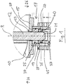
- zeigt eine Lagereinheit einer erfindungsgemäßen Klappeneinrichtung in einer Schnittansicht.
- Fig. 2
- zeigt ein Dämpfungselement der in
Fig. 1 dargestellten Lagereinheit in einem unverformten Ausgangszustand. - Fig. 3
- zeigt das Dämpfungselement gemäß
Fig. 2 in einem verformten Einbauzustand. - Die in
Fig. 1 dargestellte erfindungsgemäße Klappeneinrichtung umfasst eine platten- oder scheibenartige, lediglich teilweise gezeigte Klappe 10, die an einer Klappenwelle 12 angebracht ist. Die Klappe 10 ist in einer Rohrleitung 15 angeordnet und mittels einer Lagereinheit 17 um eine Rotationsachse R drehbar gelagert. Bei der Rohrleitung 15 kann es sich um den Abschnitt einer Abgasleitung oder um ein (rohrförmiges) Klappengehäuse handeln. Durch Drehen der Klappe 10 kann ein durch die Rohrleitung 15 geführter Gasstrom, zum Beispiel ein Abgasstrom, wahlweise freigegeben und (teilweise) gesperrt werden. - Die Lagereinheit 17 umfasst eine an der Rohrleitung 15 befestigte Lagerbuchse 19, in welcher ein Aufnahmeabschnitt 20 für einen Wellenstummel 21 der Klappenwelle 12 ausgebildet ist. Der Wellenstummel 21 ist durch eine Wellendurchführung 23 der Rohrleitung 15 geführt und mittels eines ringförmigen Lagerelements 25 mit Spiel in der Lagerbuchse 19 gelagert. Die Klappe 10 kann einseitig gelagert sein. Alternativ kann die Klappenwelle 12 zwei gegenüberliegende Wellenstummel 21 aufweisen und beidseitig mittels jeweiliger Lagereinheiten 17 gelagert sein. Einer der Wellenstummel kann mit einer Antriebseinrichtung zum Antrieb der Welle 12 verbunden sein.
- Wie in
Fig. 1 erkennbar ist das Lagerelement 25 direkt an der Rohrleitung 15 abgestützt. Grundsätzlich könnte das Lagerelement 25 auch über zumindest ein zusätzliches Bauteil an der Rohrleitung 15 abgestützt sein. In einer von der Klappe 10 weg weisenden Axialrichtung 26 stützt sich das Lagerelement 25 an einer Stufe 27 ab, die an einer Innenwand 28 eines in der Lagerbuchse 19 radial zwischen der Klappenwelle 12 und dem Aufnahmeabschnitt 20 ausgebildeten Hohlraums 30 vorgesehen ist. In dem ringspaltförmigen Hohlraum 30 befindet sich ferner ein Dämpfungselement 35 aus einem elastischen Material, vorzugsweise aus einem Drahtgestrick. - Das Dämpfungselement 35 stützt sich in einer auf die Klappe 10 zu weisenden Axialrichtung 36 direkt an dem Lagerelement 25 ab. In der entgegengesetzten Axialrichtung 26 stützt sich das Dämpfungselement 35 an einem endseitig an der Lagerbuchse 19 fixierten Abschlusselement 37 der Lagereinheit 17 ab. Das Dämpfungselement 35 ist also zwischen dem Lagerelement 25, dem Abschlusselement 37 und der Innenwand 28 eingeklemmt und sowohl axial als auch radial vorgespannt. Die Bewegungen der Klappenwelle 12 relativ zur Rohrleitung 15 und zur Lagerbuchse 19, welche während des Betriebs der Klappeneinrichtung auftreten, werden durch das eingeklemmte elastische Dämpfungselement 35 gedämpft, so dass es auch bei ausgeprägten Druckpulsationen in der Rohrleitung 15 nicht zu unerwünschten Störgeräuschen kommt. Zu der geräuschmindernden Wirkung tragen sowohl die Elastizität des eingeklemmten Dämpfungselements 35 als auch die innere Reibung bei. Die Temperaturbeständigkeit des Dämpfungselements 35 kann in weiten Bereichen durch Auswahl eines entsprechenden Materials für das Drahtgestrick angepasst werden. Auch die Steifigkeit des Dämpfungselements 35 kann durch Materialauswahl auf einen gewünschten Wert eingestellt werden.
- Um die Reibung zwischen dem Dämpfungselement 35 und der Klappenwelle 12 zu reduzieren, kann an einer radialen Innenseite 40 des Dämpfungselements 35 eine nicht dargestellte Beschichtung aus einem reibungsvermindernden Material wie zum Beispiel Graphit oder Bornitrid vorgesehen sein. Eine nicht dargestellte Ausführungsform der Erfindung sieht außerdem einen separaten Gleitring aus einem reibungsvermindernden Material vor, der zwischen dem Dämpfungselement 35 und dem Wellenstummel 21 angeordnet ist. Der Gleitring kann geschlitzt ausgeführt sein, um thermisch bedingte Ausdehnungsbewegungen des Wellenstummels 21 und/oder der Lagerbuchse 19 kompensieren zu können. Mittels eines oder mehrerer geometrischer Formschluss-Merkmale können der Gleitring und das Dämpfungselement 35 unverlierbar miteinander gekoppelt sein.
- Zur Herstellung einer erfindungsgemäßen Klappeneinrichtung wird die Klappe 10 in der Rohrleitung 15 angeordnet und der Wellenstummel 21 der Klappenwelle 12 wird durch die Wellendurchführung 23 geführt. Das Lagerelement 25 wird auf den Wellenstummel 21 aufgesteckt und die Lagerbuchse 19 wird zur Bildung der Lagereinheit 17 an der Rohrleitung 15 befestigt. Das Dämpfungselement 35 wird dann in dem in
Fig. 2 gezeigten unverformten Ausgangszustand in den Hohlraum 30 eingeführt, bis es am Lagerelement 25 anschlägt. Anschließend wird das Abschlusselement 37 in den Hohlraum 30 eingesetzt. Dabei wird das Dämpfungselement 35 durch einen Vorsprung 45 des Abschlusselements 37 beaufschlagt, so dass es zu einer axialen Vorspannung kommt. Die axiale Vorspannung wird durch das elastische Material des Dämpfungselements 35 in eine radiale Vorspannung umgesetzt, so dass das Dämpfungselement 35 auch radial in dem Hohlraum 30 eingeklemmt ist. - In dem in
Fig. 3 gezeigten Einbauzustand ist das Dämpfungselement 35 somit sowohl in axialer als auch in radialer Richtung verformt und somit vorgespannt. Die Befestigung der Lagerbuchse 19 an der Rohrleitung 15 und die Fixierung des Abschlusselements 37 an der Lagerbuchse 19 können jeweils durch Verschweißen erfolgen. - Die Erfindung ermöglicht einen geräuscharmen Betrieb von Abgasklappen und ähnlichen Klappeneinrichtungen selbst bei starker Gasdruckpulsation in der zugehörigen Rohrleitung 15.
-
- 10
- Klappe
- 12
- Klappenwelle
- 15
- Rohrleitung
- 17
- Lagereinheit
- 19
- Lagerbuchse
- 20
- Aufnahmeabschnitt
- 21
- Wellenstummel
- 23
- Wellendurchführung
- 25
- Lagerelement
- 26
- Axialrichtung
- 27
- Stufe
- 28
- Innenwand
- 30
- Hohlraum
- 35
- Dämpfungselement
- 36
- Axialrichtung
- 37
- Abschlusselement
- 40
- Innenseite
- 45
- Vorsprung
- R
- Rotationsachse
Claims (14)
- Klappeneinrichtung zur Steuerung eines Gasstroms durch eine Rohrleitung (15), insbesondere Abgasklappeneinrichtung für einen Abgasstrang eines Kraftfahrzeugs,
mit einer Klappe (10), die drehfest mit einer Klappenwelle (12) verbunden ist, und mit wenigstens einer Lagereinheit (17), mittels der die Klappenwelle (12) verdrehbar gelagert ist,
wobei zwischen der Klappenwelle (12) und einem Aufnahmeabschnitt (20) der Lagereinheit (17) ein radialer Hohlraum (30) ausgebildet ist, der in axialer Richtung (26, 36) durch jeweilige Ansatzflächen begrenzt ist,
und wobei ein Dämpfungselement (35) aus einem elastischen Material unter axialer und/oder radialer Verformung und/oder Vorspannung in dem Hohlraum (30) eingeklemmt ist. - Klappeneinrichtung nach Anspruch 1,
dadurch gekennzeichnet, dass
das Dämpfungselement (35) teilweise oder vollständig aus einem Drahtgestrick oder aus einem Faserwerkstoff gefertigt ist. - Klappeneinrichtung nach Anspruch 1 oder 2,
dadurch gekennzeichnet, dass
die Klappenwelle (12) mittels wenigstens eines vom Dämpfungselement (35) separaten Lagerelements (25) radial in dem Aufnahmeabschnitt (20) festgelegt ist, vorzugsweise mit Spiel. - Klappeneinrichtung nach Anspruch 3,
dadurch gekennzeichnet, dass
das Dämpfungselement (35) auf einer von der Klappe (10) abgewandten Seite des Lagerelements (25) axial versetzt zu diesem in dem Hohlraum (30) angeordnet ist. - Klappeneinrichtung nach Anspruch 3 oder 4,
dadurch gekennzeichnet, dass
an einer Innenwand (28) des Hohlraums (30) eine Stufe (27) ausgebildet ist, durch die das Lagerelement (25) in axialer Richtung festgelegt ist, insbesondere in einer von der Klappe (10) weg weisenden Axialrichtung (26). - Klappeneinrichtung nach einem der Ansprüche 3 bis 5,
dadurch gekennzeichnet, dass
das Lagerelement (25) direkt oder indirekt an der Rohrleitung (15) abgestützt ist. - Klappeneinrichtung nach zumindest einem der vorstehenden Ansprüche,
dadurch gekennzeichnet, dass
das Dämpfungselement (35) in einer radialen Richtung an einer Innenseite des Aufnahmeabschnitts (20) abgestützt und durch ein separates Spannteil (37) in einer axialen Spannrichtung (36) beaufschlagt ist. - Klappeneinrichtung nach zumindest einem der vorstehenden Ansprüche,
dadurch gekennzeichnet, dass
die Lagereinheit (17) eine an der Rohrleitung (15) befestigte Lagerbuchse (19) aufweist, in welcher der Aufnahmeabschnitt (20) ausgebildet ist. - Klappeneinrichtung nach zumindest einem der vorstehenden Ansprüche,
dadurch gekennzeichnet, dass
zwischen der Klappenwelle (12) und dem Dämpfungselement (35) ein Gleitelement aus einem reibungsvermindernden Material, insbesondere aus Graphit oder Bornitrid, angeordnet ist. - Klappeneinrichtung nach Anspruch 9,
dadurch gekennzeichnet, dass
das Gleitelement ringförmig ist. - Klappeneinrichtung nach Anspruch 10,
dadurch gekennzeichnet, dass
das Gleitelement in axialer Richtung geschlitzt ist. - Klappeneinrichtung nach Anspruch 10 oder 11,
dadurch gekennzeichnet, dass
das Gleitelement und das Dämpfungselement (35) unverlierbar miteinander gekoppelt sind. - Klappeneinrichtung nach zumindest einem der vorstehenden Ansprüche,
dadurch gekennzeichnet, dass
das Dämpfungselement (35) im axialen Schnitt rechteckig und/oder im radialen Schnitt kreisringförmig ist. - Verfahren zum Herstellen einer Klappeneinrichtung, insbesondere einer Klappeneinrichtung nach einem der vorstehenden Ansprüche, mit den Schritten:- Bereitstellen einer Lagereinheit (17) und einer verdrehbar zu lagernden Klappe (10), die drehfest mit einer Klappenwelle (12) verbunden ist,- Einführen der Klappenwelle (12) in einen Aufnahmeabschnitt (20) der Lagereinheit (17) derart, dass zwischen der Klappenwelle (12) und dem Aufnahmeabschnitt (20) ein radialer Hohlraum (30) ausgebildet ist, der in einer axialen Richtung (36) durch eine Ansatzfläche begrenzt ist,- Einsetzen eines Dämpfungselements (35) aus einem elastischen Material in den Hohlraum (30),- Beaufschlagen des eingesetzten Dämpfungselements (35) mittels eines Spannelements (37) zumindest in einer auf die Ansatzfläche hin weisenden axialen Spannrichtung, um das Dämpfungselement (35) unter axialer und/oder radialer Verformung und/oder Vorspannung in dem Hohlraum (30) einzuklemmen, und- direktes oder indirektes Fixieren des Spannelements (37) an der Lagereinheit (17).
Applications Claiming Priority (1)
| Application Number | Priority Date | Filing Date | Title |
|---|---|---|---|
| DE102017117289.0A DE102017117289A1 (de) | 2017-07-31 | 2017-07-31 | Klappeneinrichtung |
Publications (3)
| Publication Number | Publication Date |
|---|---|
| EP3438427A1 true EP3438427A1 (de) | 2019-02-06 |
| EP3438427B1 EP3438427B1 (de) | 2019-12-18 |
| EP3438427B2 EP3438427B2 (de) | 2023-04-26 |
Family
ID=62986002
Family Applications (1)
| Application Number | Title | Priority Date | Filing Date |
|---|---|---|---|
| EP18184282.4A Active EP3438427B2 (de) | 2017-07-31 | 2018-07-18 | Klappeneinrichtung |
Country Status (3)
| Country | Link |
|---|---|
| US (1) | US20190032607A1 (de) |
| EP (1) | EP3438427B2 (de) |
| DE (1) | DE102017117289A1 (de) |
Cited By (1)
| Publication number | Priority date | Publication date | Assignee | Title |
|---|---|---|---|---|
| WO2021073793A1 (de) * | 2019-10-16 | 2021-04-22 | Adams Gmbh | Armatur mit aufblassicherung |
Families Citing this family (6)
| Publication number | Priority date | Publication date | Assignee | Title |
|---|---|---|---|---|
| KR102148410B1 (ko) * | 2018-07-06 | 2020-08-26 | 포레시아코리아 유한회사 | 차량 배기 시스템용 밸브 조립체 |
| DE102020103420A1 (de) * | 2020-02-11 | 2021-08-12 | Friedrich Boysen GmbH & Co KG. | Klappeneinrichtung |
| DE102020204141A1 (de) | 2020-03-31 | 2021-09-30 | Daimler Ag | Klappeneinrichtung |
| DE102020118355A1 (de) * | 2020-07-13 | 2022-01-13 | Purem GmbH | Abgasklappe |
| DE102020004443A1 (de) | 2020-07-23 | 2022-01-27 | Daimler Ag | Klappeneinrichtung |
| JP7208211B2 (ja) | 2020-11-20 | 2023-01-18 | フタバ産業株式会社 | バルブの取り付け構造 |
Citations (3)
| Publication number | Priority date | Publication date | Assignee | Title |
|---|---|---|---|---|
| DE202007006463U1 (de) * | 2007-05-03 | 2008-09-11 | Capristo, Antonio | Drosselklappe und damit ausgestattete Auspuffanlage |
| DE102013206550A1 (de) * | 2013-04-12 | 2014-10-30 | Mtu Friedrichshafen Gmbh | Ventilanordnung |
| DE102015221953A1 (de) * | 2015-11-09 | 2017-05-11 | smk systeme metall kunststoff gmbh & co. kg | Abgasklappenanordnung mit geräuschoptimiertem Radialgleitlager |
Family Cites Families (19)
| Publication number | Priority date | Publication date | Assignee | Title |
|---|---|---|---|---|
| DE1177433B (de) * | 1957-08-22 | 1964-09-03 | Armaturenwerk Mosbach Heinrich | Drossel- bzw. Absperrklappe |
| US3778028A (en) * | 1972-08-02 | 1973-12-11 | Dore Co John L | Lined butterfly valve |
| AT383406B (de) † | 1977-04-01 | 1987-07-10 | Kubota Ltd | Abdichtung der nabe von drosselklappen |
| FR2439348A1 (fr) † | 1978-10-17 | 1980-05-16 | Gachot Jean | Dispositif anti-friction pour arbre de commande de vanne |
| DE8129546U1 (de) * | 1981-10-09 | 1982-03-04 | Mtu Motoren- Und Turbinen-Union Friedrichshafen Gmbh, 7990 Friedrichshafen | "lagerung fuer ein verschlussteil" |
| US4682758A (en) † | 1986-03-05 | 1987-07-28 | Keystone International, Inc. | Disk/stem connection apparatus for butterfly valve |
| DE4334180A1 (de) * | 1993-10-07 | 1995-04-13 | Bosch Gmbh Robert | Drosselvorrichtung |
| JP3059093B2 (ja) * | 1994-12-26 | 2000-07-04 | 日本碍子株式会社 | 高温流体用バタフライ弁 |
| DE19510622A1 (de) * | 1995-03-23 | 1996-09-26 | Bosch Gmbh Robert | Drosselvorrichtung und Verfahren zur Herstellung einer Drosselvorrichtung |
| DE29914381U1 (de) * | 1999-08-17 | 2000-03-02 | INA Wälzlager Schaeffler oHG, 91074 Herzogenaurach | Spannvorrichtung für einen Zugmitteltrieb |
| DE102004032856A1 (de) * | 2004-07-07 | 2006-02-02 | Faurecia Abgastechnik Gmbh | Klappenventil für die Abgasanlage eines Kraftfahrzeugs |
| DE102004046076A1 (de) * | 2004-09-23 | 2006-04-06 | Pierburg Gmbh | Abgasklappeneinrichtung |
| US20070080314A1 (en) * | 2005-10-06 | 2007-04-12 | Arvin Technologies, Inc. | Exhaust valve bushing |
| DE102006039827A1 (de) * | 2006-08-25 | 2008-02-28 | Mahle International Gmbh | Schaltvorrichtung zum Steuern einer Gasströmung |
| DE102009014140A1 (de) * | 2009-03-24 | 2010-10-07 | Mtu Friedrichshafen Gmbh | Klappenanordnung, insbesondere Abgasklappenanordnung |
| DE102009052302A1 (de) * | 2009-11-09 | 2011-05-12 | Dow Corning Gmbh | Lagerelement mit festschmierstoffhaltiger Imprägnierung |
| WO2013008268A1 (ja) † | 2011-07-11 | 2013-01-17 | 三菱電機株式会社 | バルブの軸シール構造 |
| FR2979407B1 (fr) * | 2011-08-25 | 2014-09-12 | Valeo Systemes De Controle Moteur | Vanne de circulation de fluide a blocage axial de l'arbre de commande rotatif de l'obturateur |
| WO2013134399A2 (en) * | 2012-03-06 | 2013-09-12 | KATCON USA, Inc. | Exhaust valve assembly |
-
2017
- 2017-07-31 DE DE102017117289.0A patent/DE102017117289A1/de not_active Withdrawn
-
2018
- 2018-07-18 EP EP18184282.4A patent/EP3438427B2/de active Active
- 2018-07-23 US US16/042,232 patent/US20190032607A1/en not_active Abandoned
Patent Citations (3)
| Publication number | Priority date | Publication date | Assignee | Title |
|---|---|---|---|---|
| DE202007006463U1 (de) * | 2007-05-03 | 2008-09-11 | Capristo, Antonio | Drosselklappe und damit ausgestattete Auspuffanlage |
| DE102013206550A1 (de) * | 2013-04-12 | 2014-10-30 | Mtu Friedrichshafen Gmbh | Ventilanordnung |
| DE102015221953A1 (de) * | 2015-11-09 | 2017-05-11 | smk systeme metall kunststoff gmbh & co. kg | Abgasklappenanordnung mit geräuschoptimiertem Radialgleitlager |
Cited By (1)
| Publication number | Priority date | Publication date | Assignee | Title |
|---|---|---|---|---|
| WO2021073793A1 (de) * | 2019-10-16 | 2021-04-22 | Adams Gmbh | Armatur mit aufblassicherung |
Also Published As
| Publication number | Publication date |
|---|---|
| DE102017117289A1 (de) | 2019-01-31 |
| EP3438427B2 (de) | 2023-04-26 |
| EP3438427B1 (de) | 2019-12-18 |
| US20190032607A1 (en) | 2019-01-31 |
Similar Documents
| Publication | Publication Date | Title |
|---|---|---|
| EP3438427B1 (de) | Klappeneinrichtung | |
| DE102009016597B4 (de) | Abgasklappenantrieb für ein Kraftfahrzeug | |
| DE102006003938B4 (de) | Hydraulisch gedämpfte Karosseriebefestigung mit durchragendem Bolzen | |
| DE102014118492B4 (de) | Abgasklappenantrieb | |
| EP2042702B1 (de) | Dämpfungsanordnung | |
| EP3034832B1 (de) | Ladeeinrichtung | |
| EP2929166A1 (de) | Klappenvorrichtung für eine verbrennungskraftmaschine | |
| DE102013206550B4 (de) | Ventilanordnung | |
| DE102015209042A1 (de) | Ventileinrichtung | |
| DE102016223444B3 (de) | Optimiertes Klappenventil für ein Abgasklappensystem sowie Herstellungsverfahren dafür | |
| WO2022048706A1 (de) | Ventilvorrichtung eines abgasführungsabschnitts eines abgasturboladers und abgasführungsabschnitt eines abgasturboladers | |
| DE102014118082B4 (de) | Variables Ventil vom Blattfeder-Typ | |
| DE102013106075A1 (de) | Vorrichtung zum schwingungsentkoppelten Verbinden zweier Einrichtungen einer Abgasanlage | |
| EP3179066B1 (de) | Schalldämpfer und herstellungsverfahren | |
| DE102015122379A1 (de) | Ventilvorrichtung für eine Verbrennungskraftmaschine | |
| DE10219268C1 (de) | Drosselklappeneinheit | |
| DE102006050070B4 (de) | Elastisches Lager für ein Kraftfahrzeugaggregat, Verfahren zur Herstellung eines elastischen Lagers, Anordnung zum Einstellen der Lagerungscharakteristik eines elastischen Lagers | |
| EP2808506A1 (de) | Ölfilter/Ölmodul | |
| DE102020004443A1 (de) | Klappeneinrichtung | |
| DE102021103187A1 (de) | Helmholtz-Resonator für ein Kraftfahrzeug sowie Kraftfahrzeug mit einem Helmholtz-Resonator | |
| DE102020123179A1 (de) | Ventilvorrichtung eines Abgasführungsabschnitts eines Abgasturboladers und Abgasführungsabschnitt eines Abgasturboladers | |
| WO2014194990A1 (de) | Verstellvorrichtung für einen abgasturbolader | |
| DE102020204141B4 (de) | Klappeneinrichtung und Antriebssystem mit einer derartigen Klappeneinrichtung, sowie ein Fahrzeug mit einem solchen Antriebssystem | |
| DE19548719C1 (de) | Flexible Steckverbindung für Abgasleitungen | |
| DE102016209835A1 (de) | Manschette für ein Gelenk |
Legal Events
| Date | Code | Title | Description |
|---|---|---|---|
| PUAI | Public reference made under article 153(3) epc to a published international application that has entered the european phase |
Free format text: ORIGINAL CODE: 0009012 |
|
| STAA | Information on the status of an ep patent application or granted ep patent |
Free format text: STATUS: THE APPLICATION HAS BEEN PUBLISHED |
|
| AK | Designated contracting states |
Kind code of ref document: A1 Designated state(s): AL AT BE BG CH CY CZ DE DK EE ES FI FR GB GR HR HU IE IS IT LI LT LU LV MC MK MT NL NO PL PT RO RS SE SI SK SM TR |
|
| AX | Request for extension of the european patent |
Extension state: BA ME |
|
| STAA | Information on the status of an ep patent application or granted ep patent |
Free format text: STATUS: REQUEST FOR EXAMINATION WAS MADE |
|
| 17P | Request for examination filed |
Effective date: 20190521 |
|
| RBV | Designated contracting states (corrected) |
Designated state(s): AL AT BE BG CH CY CZ DE DK EE ES FI FR GB GR HR HU IE IS IT LI LT LU LV MC MK MT NL NO PL PT RO RS SE SI SK SM TR |
|
| GRAP | Despatch of communication of intention to grant a patent |
Free format text: ORIGINAL CODE: EPIDOSNIGR1 |
|
| STAA | Information on the status of an ep patent application or granted ep patent |
Free format text: STATUS: GRANT OF PATENT IS INTENDED |
|
| INTG | Intention to grant announced |
Effective date: 20190703 |
|
| GRAS | Grant fee paid |
Free format text: ORIGINAL CODE: EPIDOSNIGR3 |
|
| GRAA | (expected) grant |
Free format text: ORIGINAL CODE: 0009210 |
|
| STAA | Information on the status of an ep patent application or granted ep patent |
Free format text: STATUS: THE PATENT HAS BEEN GRANTED |
|
| AK | Designated contracting states |
Kind code of ref document: B1 Designated state(s): AL AT BE BG CH CY CZ DE DK EE ES FI FR GB GR HR HU IE IS IT LI LT LU LV MC MK MT NL NO PL PT RO RS SE SI SK SM TR |
|
| REG | Reference to a national code |
Ref country code: CH Ref legal event code: EP |
|
| REG | Reference to a national code |
Ref country code: DE Ref legal event code: R096 Ref document number: 502018000526 Country of ref document: DE |
|
| REG | Reference to a national code |
Ref country code: IE Ref legal event code: FG4D Free format text: LANGUAGE OF EP DOCUMENT: GERMAN |
|
| REG | Reference to a national code |
Ref country code: AT Ref legal event code: REF Ref document number: 1214848 Country of ref document: AT Kind code of ref document: T Effective date: 20200115 |
|
| REG | Reference to a national code |
Ref country code: NL Ref legal event code: MP Effective date: 20191218 |
|
| PG25 | Lapsed in a contracting state [announced via postgrant information from national office to epo] |
Ref country code: BG Free format text: LAPSE BECAUSE OF FAILURE TO SUBMIT A TRANSLATION OF THE DESCRIPTION OR TO PAY THE FEE WITHIN THE PRESCRIBED TIME-LIMIT Effective date: 20200318 Ref country code: NO Free format text: LAPSE BECAUSE OF FAILURE TO SUBMIT A TRANSLATION OF THE DESCRIPTION OR TO PAY THE FEE WITHIN THE PRESCRIBED TIME-LIMIT Effective date: 20200318 Ref country code: FI Free format text: LAPSE BECAUSE OF FAILURE TO SUBMIT A TRANSLATION OF THE DESCRIPTION OR TO PAY THE FEE WITHIN THE PRESCRIBED TIME-LIMIT Effective date: 20191218 Ref country code: LV Free format text: LAPSE BECAUSE OF FAILURE TO SUBMIT A TRANSLATION OF THE DESCRIPTION OR TO PAY THE FEE WITHIN THE PRESCRIBED TIME-LIMIT Effective date: 20191218 Ref country code: SE Free format text: LAPSE BECAUSE OF FAILURE TO SUBMIT A TRANSLATION OF THE DESCRIPTION OR TO PAY THE FEE WITHIN THE PRESCRIBED TIME-LIMIT Effective date: 20191218 Ref country code: GR Free format text: LAPSE BECAUSE OF FAILURE TO SUBMIT A TRANSLATION OF THE DESCRIPTION OR TO PAY THE FEE WITHIN THE PRESCRIBED TIME-LIMIT Effective date: 20200319 Ref country code: LT Free format text: LAPSE BECAUSE OF FAILURE TO SUBMIT A TRANSLATION OF THE DESCRIPTION OR TO PAY THE FEE WITHIN THE PRESCRIBED TIME-LIMIT Effective date: 20191218 |
|
| REG | Reference to a national code |
Ref country code: LT Ref legal event code: MG4D |
|
| PG25 | Lapsed in a contracting state [announced via postgrant information from national office to epo] |
Ref country code: HR Free format text: LAPSE BECAUSE OF FAILURE TO SUBMIT A TRANSLATION OF THE DESCRIPTION OR TO PAY THE FEE WITHIN THE PRESCRIBED TIME-LIMIT Effective date: 20191218 Ref country code: RS Free format text: LAPSE BECAUSE OF FAILURE TO SUBMIT A TRANSLATION OF THE DESCRIPTION OR TO PAY THE FEE WITHIN THE PRESCRIBED TIME-LIMIT Effective date: 20191218 |
|
| PG25 | Lapsed in a contracting state [announced via postgrant information from national office to epo] |
Ref country code: AL Free format text: LAPSE BECAUSE OF FAILURE TO SUBMIT A TRANSLATION OF THE DESCRIPTION OR TO PAY THE FEE WITHIN THE PRESCRIBED TIME-LIMIT Effective date: 20191218 |
|
| PG25 | Lapsed in a contracting state [announced via postgrant information from national office to epo] |
Ref country code: EE Free format text: LAPSE BECAUSE OF FAILURE TO SUBMIT A TRANSLATION OF THE DESCRIPTION OR TO PAY THE FEE WITHIN THE PRESCRIBED TIME-LIMIT Effective date: 20191218 Ref country code: NL Free format text: LAPSE BECAUSE OF FAILURE TO SUBMIT A TRANSLATION OF THE DESCRIPTION OR TO PAY THE FEE WITHIN THE PRESCRIBED TIME-LIMIT Effective date: 20191218 Ref country code: RO Free format text: LAPSE BECAUSE OF FAILURE TO SUBMIT A TRANSLATION OF THE DESCRIPTION OR TO PAY THE FEE WITHIN THE PRESCRIBED TIME-LIMIT Effective date: 20191218 Ref country code: PT Free format text: LAPSE BECAUSE OF FAILURE TO SUBMIT A TRANSLATION OF THE DESCRIPTION OR TO PAY THE FEE WITHIN THE PRESCRIBED TIME-LIMIT Effective date: 20200513 |
|
| PG25 | Lapsed in a contracting state [announced via postgrant information from national office to epo] |
Ref country code: SM Free format text: LAPSE BECAUSE OF FAILURE TO SUBMIT A TRANSLATION OF THE DESCRIPTION OR TO PAY THE FEE WITHIN THE PRESCRIBED TIME-LIMIT Effective date: 20191218 Ref country code: SK Free format text: LAPSE BECAUSE OF FAILURE TO SUBMIT A TRANSLATION OF THE DESCRIPTION OR TO PAY THE FEE WITHIN THE PRESCRIBED TIME-LIMIT Effective date: 20191218 Ref country code: IS Free format text: LAPSE BECAUSE OF FAILURE TO SUBMIT A TRANSLATION OF THE DESCRIPTION OR TO PAY THE FEE WITHIN THE PRESCRIBED TIME-LIMIT Effective date: 20200418 |
|
| REG | Reference to a national code |
Ref country code: DE Ref legal event code: R026 Ref document number: 502018000526 Country of ref document: DE |
|
| PLBI | Opposition filed |
Free format text: ORIGINAL CODE: 0009260 |
|
| PLAX | Notice of opposition and request to file observation + time limit sent |
Free format text: ORIGINAL CODE: EPIDOSNOBS2 |
|
| 26 | Opposition filed |
Opponent name: FAURECIA SYSTEMES D'ECHAPPEMENT Effective date: 20200917 |
|
| PG25 | Lapsed in a contracting state [announced via postgrant information from national office to epo] |
Ref country code: DK Free format text: LAPSE BECAUSE OF FAILURE TO SUBMIT A TRANSLATION OF THE DESCRIPTION OR TO PAY THE FEE WITHIN THE PRESCRIBED TIME-LIMIT Effective date: 20191218 Ref country code: ES Free format text: LAPSE BECAUSE OF FAILURE TO SUBMIT A TRANSLATION OF THE DESCRIPTION OR TO PAY THE FEE WITHIN THE PRESCRIBED TIME-LIMIT Effective date: 20191218 |
|
| PG25 | Lapsed in a contracting state [announced via postgrant information from national office to epo] |
Ref country code: SI Free format text: LAPSE BECAUSE OF FAILURE TO SUBMIT A TRANSLATION OF THE DESCRIPTION OR TO PAY THE FEE WITHIN THE PRESCRIBED TIME-LIMIT Effective date: 20191218 |
|
| PG25 | Lapsed in a contracting state [announced via postgrant information from national office to epo] |
Ref country code: IT Free format text: LAPSE BECAUSE OF FAILURE TO SUBMIT A TRANSLATION OF THE DESCRIPTION OR TO PAY THE FEE WITHIN THE PRESCRIBED TIME-LIMIT Effective date: 20191218 |
|
| PG25 | Lapsed in a contracting state [announced via postgrant information from national office to epo] |
Ref country code: MC Free format text: LAPSE BECAUSE OF FAILURE TO SUBMIT A TRANSLATION OF THE DESCRIPTION OR TO PAY THE FEE WITHIN THE PRESCRIBED TIME-LIMIT Effective date: 20191218 Ref country code: PL Free format text: LAPSE BECAUSE OF FAILURE TO SUBMIT A TRANSLATION OF THE DESCRIPTION OR TO PAY THE FEE WITHIN THE PRESCRIBED TIME-LIMIT Effective date: 20191218 |
|
| PLBB | Reply of patent proprietor to notice(s) of opposition received |
Free format text: ORIGINAL CODE: EPIDOSNOBS3 |
|
| REG | Reference to a national code |
Ref country code: BE Ref legal event code: MM Effective date: 20200731 |
|
| PG25 | Lapsed in a contracting state [announced via postgrant information from national office to epo] |
Ref country code: LU Free format text: LAPSE BECAUSE OF NON-PAYMENT OF DUE FEES Effective date: 20200718 |
|
| PG25 | Lapsed in a contracting state [announced via postgrant information from national office to epo] |
Ref country code: BE Free format text: LAPSE BECAUSE OF NON-PAYMENT OF DUE FEES Effective date: 20200731 |
|
| PG25 | Lapsed in a contracting state [announced via postgrant information from national office to epo] |
Ref country code: IE Free format text: LAPSE BECAUSE OF NON-PAYMENT OF DUE FEES Effective date: 20200718 |
|
| REG | Reference to a national code |
Ref country code: CH Ref legal event code: PL |
|
| PG25 | Lapsed in a contracting state [announced via postgrant information from national office to epo] |
Ref country code: LI Free format text: LAPSE BECAUSE OF NON-PAYMENT OF DUE FEES Effective date: 20210731 Ref country code: CH Free format text: LAPSE BECAUSE OF NON-PAYMENT OF DUE FEES Effective date: 20210731 |
|
| PG25 | Lapsed in a contracting state [announced via postgrant information from national office to epo] |
Ref country code: TR Free format text: LAPSE BECAUSE OF FAILURE TO SUBMIT A TRANSLATION OF THE DESCRIPTION OR TO PAY THE FEE WITHIN THE PRESCRIBED TIME-LIMIT Effective date: 20191218 Ref country code: MT Free format text: LAPSE BECAUSE OF FAILURE TO SUBMIT A TRANSLATION OF THE DESCRIPTION OR TO PAY THE FEE WITHIN THE PRESCRIBED TIME-LIMIT Effective date: 20191218 Ref country code: CY Free format text: LAPSE BECAUSE OF FAILURE TO SUBMIT A TRANSLATION OF THE DESCRIPTION OR TO PAY THE FEE WITHIN THE PRESCRIBED TIME-LIMIT Effective date: 20191218 |
|
| PG25 | Lapsed in a contracting state [announced via postgrant information from national office to epo] |
Ref country code: MK Free format text: LAPSE BECAUSE OF FAILURE TO SUBMIT A TRANSLATION OF THE DESCRIPTION OR TO PAY THE FEE WITHIN THE PRESCRIBED TIME-LIMIT Effective date: 20191218 |
|
| APBM | Appeal reference recorded |
Free format text: ORIGINAL CODE: EPIDOSNREFNO |
|
| APBP | Date of receipt of notice of appeal recorded |
Free format text: ORIGINAL CODE: EPIDOSNNOA2O |
|
| APAH | Appeal reference modified |
Free format text: ORIGINAL CODE: EPIDOSCREFNO |
|
| APBU | Appeal procedure closed |
Free format text: ORIGINAL CODE: EPIDOSNNOA9O |
|
| PUAH | Patent maintained in amended form |
Free format text: ORIGINAL CODE: 0009272 |
|
| STAA | Information on the status of an ep patent application or granted ep patent |
Free format text: STATUS: PATENT MAINTAINED AS AMENDED |
|
| GRAT | Correction requested after decision to grant or after decision to maintain patent in amended form |
Free format text: ORIGINAL CODE: EPIDOSNCDEC |
|
| 27A | Patent maintained in amended form |
Effective date: 20230426 |
|
| AK | Designated contracting states |
Kind code of ref document: B2 Designated state(s): AL AT BE BG CH CY CZ DE DK EE ES FI FR GB GR HR HU IE IS IT LI LT LU LV MC MK MT NL NO PL PT RO RS SE SI SK SM TR |
|
| REG | Reference to a national code |
Ref country code: DE Ref legal event code: R102 Ref document number: 502018000526 Country of ref document: DE |
|
| REG | Reference to a national code |
Ref country code: AT Ref legal event code: MM01 Ref document number: 1214848 Country of ref document: AT Kind code of ref document: T Effective date: 20230718 |
|
| PG25 | Lapsed in a contracting state [announced via postgrant information from national office to epo] |
Ref country code: AT Free format text: LAPSE BECAUSE OF NON-PAYMENT OF DUE FEES Effective date: 20230718 |
|
| PG25 | Lapsed in a contracting state [announced via postgrant information from national office to epo] |
Ref country code: AT Free format text: LAPSE BECAUSE OF NON-PAYMENT OF DUE FEES Effective date: 20230718 |
|
| PGFP | Annual fee paid to national office [announced via postgrant information from national office to epo] |
Ref country code: GB Payment date: 20250722 Year of fee payment: 8 |
|
| PGFP | Annual fee paid to national office [announced via postgrant information from national office to epo] |
Ref country code: FR Payment date: 20250725 Year of fee payment: 8 |
|
| PGFP | Annual fee paid to national office [announced via postgrant information from national office to epo] |
Ref country code: CZ Payment date: 20250711 Year of fee payment: 8 |
|
| PGFP | Annual fee paid to national office [announced via postgrant information from national office to epo] |
Ref country code: DE Payment date: 20250926 Year of fee payment: 8 |
|
| PGFP | Annual fee paid to national office [announced via postgrant information from national office to epo] |
Ref country code: AT Payment date: 20260410 Year of fee payment: 5 |