EP3438428A1 - 2-stufiges turbosystem und verfahren zur steuerung eines 2-stufigen turbosystems - Google Patents
2-stufiges turbosystem und verfahren zur steuerung eines 2-stufigen turbosystems Download PDFInfo
- Publication number
- EP3438428A1 EP3438428A1 EP17774060.2A EP17774060A EP3438428A1 EP 3438428 A1 EP3438428 A1 EP 3438428A1 EP 17774060 A EP17774060 A EP 17774060A EP 3438428 A1 EP3438428 A1 EP 3438428A1
- Authority
- EP
- European Patent Office
- Prior art keywords
- pressure stage
- passage
- low
- rotation speed
- engine
- Prior art date
- Legal status (The legal status is an assumption and is not a legal conclusion. Google has not performed a legal analysis and makes no representation as to the accuracy of the status listed.)
- Granted
Links
Images



Classifications
-
- F—MECHANICAL ENGINEERING; LIGHTING; HEATING; WEAPONS; BLASTING
- F02—COMBUSTION ENGINES; HOT-GAS OR COMBUSTION-PRODUCT ENGINE PLANTS
- F02B—INTERNAL-COMBUSTION PISTON ENGINES; COMBUSTION ENGINES IN GENERAL
- F02B37/00—Engines characterised by provision of pumps driven at least for part of the time by exhaust
- F02B37/02—Gas passages between engine outlet and pump drive, e.g. reservoirs
- F02B37/025—Multiple scrolls or multiple gas passages guiding the gas to the pump drive
-
- F—MECHANICAL ENGINEERING; LIGHTING; HEATING; WEAPONS; BLASTING
- F02—COMBUSTION ENGINES; HOT-GAS OR COMBUSTION-PRODUCT ENGINE PLANTS
- F02B—INTERNAL-COMBUSTION PISTON ENGINES; COMBUSTION ENGINES IN GENERAL
- F02B37/00—Engines characterised by provision of pumps driven at least for part of the time by exhaust
-
- F—MECHANICAL ENGINEERING; LIGHTING; HEATING; WEAPONS; BLASTING
- F02—COMBUSTION ENGINES; HOT-GAS OR COMBUSTION-PRODUCT ENGINE PLANTS
- F02B—INTERNAL-COMBUSTION PISTON ENGINES; COMBUSTION ENGINES IN GENERAL
- F02B37/00—Engines characterised by provision of pumps driven at least for part of the time by exhaust
- F02B37/004—Engines characterised by provision of pumps driven at least for part of the time by exhaust with exhaust drives arranged in series
-
- F—MECHANICAL ENGINEERING; LIGHTING; HEATING; WEAPONS; BLASTING
- F02—COMBUSTION ENGINES; HOT-GAS OR COMBUSTION-PRODUCT ENGINE PLANTS
- F02B—INTERNAL-COMBUSTION PISTON ENGINES; COMBUSTION ENGINES IN GENERAL
- F02B37/00—Engines characterised by provision of pumps driven at least for part of the time by exhaust
- F02B37/013—Engines characterised by provision of pumps driven at least for part of the time by exhaust with exhaust-driven pumps arranged in series
-
- F—MECHANICAL ENGINEERING; LIGHTING; HEATING; WEAPONS; BLASTING
- F02—COMBUSTION ENGINES; HOT-GAS OR COMBUSTION-PRODUCT ENGINE PLANTS
- F02B—INTERNAL-COMBUSTION PISTON ENGINES; COMBUSTION ENGINES IN GENERAL
- F02B37/00—Engines characterised by provision of pumps driven at least for part of the time by exhaust
- F02B37/12—Control of the pumps
- F02B37/18—Control of the pumps by bypassing exhaust from the inlet to the outlet of turbine or to the atmosphere
-
- F—MECHANICAL ENGINEERING; LIGHTING; HEATING; WEAPONS; BLASTING
- F02—COMBUSTION ENGINES; HOT-GAS OR COMBUSTION-PRODUCT ENGINE PLANTS
- F02B—INTERNAL-COMBUSTION PISTON ENGINES; COMBUSTION ENGINES IN GENERAL
- F02B37/00—Engines characterised by provision of pumps driven at least for part of the time by exhaust
- F02B37/12—Control of the pumps
- F02B37/18—Control of the pumps by bypassing exhaust from the inlet to the outlet of turbine or to the atmosphere
- F02B37/183—Arrangements of bypass valves or actuators therefor
-
- F—MECHANICAL ENGINEERING; LIGHTING; HEATING; WEAPONS; BLASTING
- F05—INDEXING SCHEMES RELATING TO ENGINES OR PUMPS IN VARIOUS SUBCLASSES OF CLASSES F01-F04
- F05D—INDEXING SCHEME FOR ASPECTS RELATING TO NON-POSITIVE-DISPLACEMENT MACHINES OR ENGINES, GAS-TURBINES OR JET-PROPULSION PLANTS
- F05D2220/00—Application
- F05D2220/40—Application in turbochargers
-
- F—MECHANICAL ENGINEERING; LIGHTING; HEATING; WEAPONS; BLASTING
- F05—INDEXING SCHEMES RELATING TO ENGINES OR PUMPS IN VARIOUS SUBCLASSES OF CLASSES F01-F04
- F05D—INDEXING SCHEME FOR ASPECTS RELATING TO NON-POSITIVE-DISPLACEMENT MACHINES OR ENGINES, GAS-TURBINES OR JET-PROPULSION PLANTS
- F05D2240/00—Components
- F05D2240/10—Stators
- F05D2240/12—Fluid guiding means, e.g. vanes
- F05D2240/128—Nozzles
-
- Y—GENERAL TAGGING OF NEW TECHNOLOGICAL DEVELOPMENTS; GENERAL TAGGING OF CROSS-SECTIONAL TECHNOLOGIES SPANNING OVER SEVERAL SECTIONS OF THE IPC; TECHNICAL SUBJECTS COVERED BY FORMER USPC CROSS-REFERENCE ART COLLECTIONS [XRACs] AND DIGESTS
- Y02—TECHNOLOGIES OR APPLICATIONS FOR MITIGATION OR ADAPTATION AGAINST CLIMATE CHANGE
- Y02T—CLIMATE CHANGE MITIGATION TECHNOLOGIES RELATED TO TRANSPORTATION
- Y02T10/00—Road transport of goods or passengers
- Y02T10/10—Internal combustion engine [ICE] based vehicles
- Y02T10/12—Improving ICE efficiencies
Definitions
- the present disclosure relates to a two-stage turbo system, which is a supercharging system for an engine.
- a two-stage turbo system is known as a supercharging system that can be applied to an engine such as a diesel engine.
- a two-stage turbo system is regarded as a promising supercharging system which can be applied to an existing diesel engine without adding extensive modification, which can achieve both torque up and high output at a low speed, and which has an improved response (transient response performance).
- a two-stage turbo system includes a high-pressure stage turbocharger and a low-pressure stage connected in series, whereby it is possible to switch stages of supercharging through switching of the flow passage of the exhaust passage by controlling the opening degree of various valves disposed in the exhaust passage.
- exhaust gas has a small flow rate when the engine is at a low speed, and the flow passage of the exhaust gas is switched so that two-stage supercharging is performed by allowing the exhaust gas to flow through the high-pressure stage turbocharger and the low-pressure stage turbocharger in this order.
- the exhaust passage is switched so as to allow a part of exhaust gas to flow directly to the low-pressure stage turbocharger without passing through the high-pressure stage turbocharger.
- the flow passage of the exhaust gas is switched so that one-stage supercharging is performed by allowing the entire exhaust gas, which has a high flow rate, to flow into the low-pressure stage turbocharger directly.
- a small-sized turbocharger is mounted to the high-pressure stage side of the two-stage turbo system, and a large-sized turbocharger is mounted to the low-pressure stage side. Accordingly, it is possible to expand the operational range of the compressor by making use of the range of the low flow rate side of the high-pressure stage turbocharger and the range of the high flow rate side of the low-pressure stage turbocharger.
- the large-sized turbine of the low-pressure stage turbocharger has a greater weight than a small-sized turbine, and thus the rotation speed of the turbine is less likely to increase when the engine is at a low speed.
- Patent Document 1 proposes providing a VG turbo as the low-pressure stage turbocharger.
- Patent Document 2 proposes applying a twin scroll to a scroll part of the low-pressure stage turbocharger.
- a scroll part formed along the circumferential direction of the rotational axis of a turbine has a structure with two passages extending side by side in the axial direction of the rotational axis, whereby the flow rate of exhaust gas is introduced into the turbine through two separate passages, which makes it possible to drive the turbine without attenuating the pressure of the exhaust gas.
- the U/Co property refers to a property representing the relationship between the turbine operation speed ratio (U/Co) and the turbine efficiency, where U is the circumferential speed of the turbine T, Co is a theoretical speed defined from a pressure ratio of the inlet and the outlet of the turbine and the inlet temperature.
- an object of at least one embodiment of the present invention is to provide a two-stage turbo system with an improved supercharging response, whereby it is possible to generate a necessary boost pressure over a broad operational range of an engine.
- a two-stage turbo system with an improved supercharging response, whereby it is possible to generate a necessary boost pressure over a broad operational range of an engine.
- an expression of relative or absolute arrangement such as “in a direction”, “along a direction”, “parallel”, “orthogonal”, “centered”, “concentric” and “coaxial” shall not be construed as indicating only the arrangement in a strict literal sense, but also includes a state where the arrangement is relatively displaced by a tolerance, or by an angle or a distance whereby it is possible to achieve the same function.
- an expression of an equal state such as “same” “equal” and “uniform” shall not be construed as indicating only the state in which the feature is strictly equal, but also includes a state in which there is a tolerance or a difference that can still achieve the same function.
- an expression of a shape such as a rectangular shape or a cylindrical shape shall not be construed as only the geometrically strict shape, but also includes a shape with unevenness or chamfered corners within the range in which the same effect can be achieved.
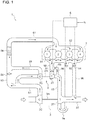
- FIG. 1 is a schematic diagram showing a two-stage turbo system 1 applied to an engine 7 according to an embodiment of the present invention.
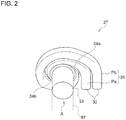
- FIG. 2 is a schematic diagram of a scroll part 3S of a low-pressure stage turbine 3T of a low-pressure stage turbocharger 3 according to an embodiment of the present invention.
- the scroll part 3S has a double scroll structure including two scroll passages P.
- FIG. 3 is a cross-sectional view of a scroll part 3S of a low-pressure stage turbine 3T of a low-pressure stage turbocharger 3 according to an embodiment of the present invention, taken along the circumferential direction, which is a view of a part of the scroll part 3S shown in FIG. 2 as seen in the direction A.
- FIG. 3 is a schematic diagram showing a two-stage turbo system 1 applied to an engine 7 according to an embodiment of the present invention.
- FIG. 2 is a schematic diagram of a scroll part 3S of a low-pressure stage turbine 3T of a low-pressure stage turbocharger 3
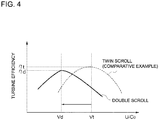
- FIG. 4 is a diagram for describing the U/Co property of a low-pressure stage turbocharger including a scroll part 3S having a double scroll structure according to an embodiment of the present invention.
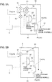
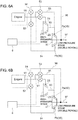
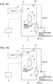
- FIGs. 5A to 5D are each a simplified schematic diagram showing the side of an exhaust passage 9 of the two-stage turbo system 1 according to an embodiment of the present invention.
- FIGs. 6A to 6D are each a schematic diagram for describing the operation mode of the two-stage turbo system 1 corresponding to FIG. 5A .
- FIGs. 7A to 7D are each a schematic diagram for describing the operation mode of the two-stage turbo system 1 corresponding to FIG. 5B .
- the two-stage turbo system 1 is a supercharging system to be applied to the engine 7.
- the engine 7 is, for instance, a diesel engine or a gasoline engine including one or more cylinders (four cylinders in FIG. 1 ).
- the two-stage turbo system 1 can be also applied to an engine 7 of various fields, such as automobile, truck, bus, ship, industrial engine, etc.
- the two-stage turbo system 1 includes two turbochargers: a high-pressure stage turbocharger 2 and a low-pressure stage turbocharger 3.
- Each of the turbochargers includes a compressor C (2C, 3C) disposed in an intake passage 8 of the engine 7 and a turbine T (2T, 3T) disposed in an exhaust passage 9 of the engine 7.
- the turbine T includes a turbine housing and a turbine wheel (reference numeral 31 in FIG. 3 ), and the compressor C includes a compressor housing and a compressor wheel. Further, the compressor wheel of the compressor C and the turbine wheel of the turbine T are coupled via a shaft m (2m, 3m).
- exhaust gas discharged from the combustion chamber (not shown) of the engine 7 rotary-drives the turbine wheel when passing through the exhaust passage 9 toward the outside. Accordingly, the compressor wheel coupled coaxially to the turbine wheel 31 via the shaft m is rotary driven, and intake air passing through the intake passage 8 is compressed. More specifically, exhaust gas after passing through the scroll part S of the turbocharger blows into the turbine wheel from a nozzle flow passage E, and thereby the turbine T is rotary driven (see FIG. 3 ).
- the above high-pressure stage turbocharger 2 and the low-pressure stage turbocharger 3 are connected in series in the two-stage turbo system 1. Specifically, as shown in FIGs. 1 , 5A to 7D , in the exhaust passage 9, the turbine T of the high-pressure stage turbocharger 2 (high-pressure stage turbine 2T) is disposed on the upstream side in the exhaust passage 9, which is a side relatively close to the engine 7 with respect to the flow direction of the exhaust gas, and the turbine T of the low-pressure stage turbocharger 3 (low-pressure stage turbine 3T) is disposed on the downstream side in the exhaust passage 9, which is a side relatively far from the engine 7 with respect to the flow direction of exhaust gas compared to the high-pressure stage turbine 2T.
- the compressor C of the low-pressure stage turbocharger 3 (low-pressure stage compressor 3C) is disposed on the upstream side in the intake passage 8
- the compressor C of the high-pressure stage compressor 2 (high-pressure stage compressor 2C) is disposed in the intake passage 8 on the downstream side of the low-pressure stage compressor 3C (see FIG. 1 ).
- the above two superchargers are disposed in series in the intake passage 8 and the exhaust passage 9.
- the low-pressure stage turbocharger 3 is larger in size than the high-pressure stage turbocharger 2.
- a larger turbocharger has more weight, and a weight increase causes the inertia to increase.
- the rotation speed of the turbine T becomes less likely to increase at the low speed time of the engine 7, and the response performance deteriorates.
- a larger turbocharger has a better turbine efficiency in a region where the exhaust gas flow rate is high, compared to a smaller turbocharger.
- the two-stage turbo system 1 is configured to cover the flow rate range of the low flow rate side with the relatively small high-pressure stage turbocharger 2, and to cover the flow rate range of the high flow rate side with the relatively large low-pressure stage turbocharger 3.
- the two-stage turbo system 1 controls the valve device 5 disposed in the exhaust passage 9 with the control device 6, for instance, to switch the flow passage of the exhaust passage 9 (exhaust passages I to IV described below) in accordance with the operation conditions of the engine 7, thereby switching the operation mode (turbocharger to be used) in the single stage supercharging and the two-stage supercharging. Accordingly, the response at a low speed time of the engine 7 is improved, while generating a necessary boost pressure over a broad operational range of the engine 7.
- the above single stage supercharging refers to an operation mode in which the engine 7 is supercharged by using the low-pressure stage turbocharger 3 alone
- the two-stage supercharging refers to an operation mode in which supercharging is performed by using both of the high-pressure stage turbocharger 2 and the low-pressure stage turbocharger 3.
- the scroll part 3S of the low-pressure stage turbine 3T of the low-pressure stage turbocharger 3 of the present embodiment will be described with reference to FIGs. 2 and 3 .
- the scroll part 3S forms a part of the turbine housing.
- the scroll part 3S of the low-pressure stage turbine 3T of the present embodiment includes at least two scroll passages P: the first scroll passage Pa, and the second scroll passage Pb.
- the first range Ra of the nozzle flow passage E into which exhaust gas passing through the first scroll passage Pa is introduced does not overlap with the second range Rb of the nozzle flow passage E into which exhaust gas passing through the second scroll passage pb is introduced, in the circumferential direction of the nozzle flow passage E.
- the above nozzle flow passage E is a space (flow passage) positioned at a boundary connecting a wheel housing chamber 31r that houses the turbine wheel 31 and the scroll part 3S, and is formed by the inner wall of the turbine housing, around the turbine wheel 31 of the low-pressure stage turbine 3T (see FIG. 3 ).
- exhaust gas having entered from the inlet 32 (see FIG. 2 ) of the scroll part S (low-pressure stage turbine 3T) and passed through the first scroll passage Pa blows into the turbine wheel 31 via the first range Ra of the nozzle flow passage E, while exhaust gas having passed through the second scroll passage Pa blows into the turbine wheel 31 via the second range Rb of the nozzle flow passage E.
- exhaust gas passes through a low-pressure stage downstream passage 97 from an outlet 33 of the low-pressure stage turbine 3T disposed along the axial direction of the rotational axis L of the shaft m.
- the scroll part 3S of the low-pressure stage turbine 3T has a double scroll structure including the first scroll passage Pa and the second scroll passage Pb described above. More specifically, in the double scroll structure, the first scroll passage Pa and the second scroll passage Pb are disposed next to each other along the circumferential direction.
- the nozzle flow passage E is formed into an annular shape over the entire outer perimeter of the turbine wheel 31 shown in a circular shape.
- the turbine housing includes two tongues 34 formed thereon, including a tongue on the side connected to the passage wall of the radially inner side of the first scroll passage Pa (first tongue 34a) and a tongue on the side connected to the passage wall of the radially outer side of the first scroll passage Pa (second tongue 34b).
- first tongue 34a is the tongue on the side connected to the passage wall on the radially outer side of the second scroll passage Pa
- the second tongue 34b is the tongue on the side connected to the passage wall on the inner side of the second scroll passage Pa.
- the first range Ra of the nozzle flow passage E is formed on a side (semi-perimeter portion) of the boundary line RL
- the second range Rb of the nozzle flow passage E is formed on the opposite side (semi-perimeter portion) of the boundary line RL.
- the scroll part 3S is formed such that the first range Ra and the second range Rb do not have a range (portion) overlapping with each other.
- the passage walls of the first scroll passage Pa and the second scroll passage Pb are connected to different portions of the turbine housing forming the nozzle flow passage E (see FIG. 2 ).
- the size of the nozzle flow passage E upon introduction of the entire amount of the flow rate of exhaust gas would be smaller than that in a case where exhaust gas is introduced into the two scroll passages P (Pa, Pb) separately.
- the first range Ra and the second range Rb have the same angular range (same size).
- the range of the nozzle flow passage E into which exhaust gas can be introduced from one of the scroll passages is about a half of the entire perimeter of the nozzle flow passage E.
- exhaust gas can be introduced into the low-pressure stage turbine 3T without dispersing (attenuating) the pressure of exhaust gas over the entire range of the nozzle flow passage E upon introduction of exhaust gas into the nozzle flow passage E, and thus it is possible to drive the low-pressure stage turbine 3T more quickly at the low speed time of the engine 7.
- each of the two passages of the twin scroll are configured to introduce exhaust gas uniformly over the entire perimeter of the turbine wheel 31. That is, the two passages of the twin scroll introduce exhaust gas into the same range of the nozzle flow passage E, and thus the ranges of the nozzle flow passage E in communication with the respective two scroll passages have an overlapping portion in the circumferential direction of the nozzle flow passage E. Further, when the entire amount of exhaust gas is introduced into one of the two scroll passages, the exhaust gas is introduced over the entire perimeter of the turbine wheel 31.
- the U/Co property represents the relationship between the turbine efficiency and the turbine operation speed ratio (U/Co), which is a speed ratio of the circumferential speed (U) of the turbine T to the theoretical speed (Co), and is shown in a chart where x-axis is the turbine operation speed ratio (U/Co) and y-axis is the turbine efficiency.
- the circumferential speed (U) of the turbine T is the rotation speed obtained from the number of rotation of the turbine T
- the theoretical speed (Co) of the turbine T is a speed defined from a pressure ratio of the inlet and the outlet of the turbine and the inlet temperature.
- the efficiency of the U/Co property shifts toward the low speed ratio side, it means that the efficiency is high at the low speed time of the engine, such as the start of rotation of the turbine T where the circumferential speed (U) of the turbine T is low relative to the theoretical speed (Co).
- the flow rate of exhaust gas is low, such as the low speed time of the engine 7, it is possible to rotate the low-pressure stage turbine 3T efficiently.
- the U/CO property is shown for two turbochargers which are different form each other only in the structure of the scroll part, which is a twin scroll structure or a double scroll structure.
- the turbine operation speed ratio at the highest point ( ⁇ t) of the turbine efficiency of the turbocharger including the twin scroll is Vt
- the turbine operation speed ratio of the highest point ( ⁇ d) of the turbine efficiency of the turbocharger including the double scroll structure is Vd.
- both turbochargers each have a U/Co property having a convex shape protruding from x-axis across the speed ratio corresponding to the highest point ( ⁇ t, ⁇ d).
- the turbocharger with the double scroll structure has a higher turbine efficiency than the turbocharger with the twin scroll, and thus has a high efficiency at the low-speed side of the engine 7.
- each of the first scroll passage Pa and the second scroll passage Pb is configured to introduce exhaust gas partially from different directions into the nozzle flow passage E formed around the turbine wheel 31. That is, the scroll part 3S of the low-pressure stage turbine 3T allows exhaust gas discharged from the engine 7 only to a part of the plurality of scroll passages P (in FIGs. 1 to 4 , the first scroll passage Pi), and thereby it is possible to limit the range of the nozzle flow passage E into which exhaust gas is introduced only to the part.
- each of the plurality of scroll passages P not overlapping with each other in the circumferential direction of the nozzle flow passage E, it is possible to shift the highest point of the turbine efficiency in the U/Co property to the low U/Co side, compared to a case in which the scroll passages P are overlapped in the circumferential direction, like the twin scroll.
- the response performance of a typical low-pressure stage turbocharger is low at the low speed time of the engine, as described above, and thus the high-pressure stage turbocharger mainly covers the boost pressure required at the low speed time of the engine, in the present embodiment, it is possible to increase the contribution from the low-pressure stage turbocharger 3, and the response of supercharging is improved.
- the entire perimeter of the nozzle flow passage E is divided equally into the first range Ra and the second range Rb not overlapping with each other across the boundary line RL.
- this embodiment is not limitative.
- the entire range formed by the first range Ra and the second range Rb does not need to be the entire perimeter of the nozzle flow passage E.
- exhaust gas may not necessarily be introduced directly after passing through the scroll passage P.
- the angular range of the first range Ra and the angular range of the second range Rb are the same.
- the angular range of the first range Ra and the angular range of the second range Rb may be different. It is possible to improve the rotation torque of the turbine wheel with exhaust gas in accordance with the angular range of the first range Ra to which the first low-pressure stage introduction passage 93 is connected.
- the scroll part 3S of the low-pressure stage turbine 3T has the double scroll structure as described above.
- the scroll part 3S of the low-pressure stage turbine 3T may include two or more scroll passages P.
- the scroll part 3S is configured such that the ranges of the nozzle flow passage E corresponding to the respective passages of the at least two scroll passages P (the first scroll passage Pa and the second scroll passage Pb) do not overlap.
- FIG. 1 the overall configuration of the engine 7 including the two-stage turbo system 1 will be described with reference to FIGs. 1 , 5A to 7D . While the intake passage 8 of the engine 7 is not shown in FIGs. 5A to 7D , the intake passage 8 shown in FIG. 1 is connected to the engine 7.
- the intake passage 8 of the engine 7 includes a main intake passage 81 for supplying intake air (air) taken in from an intake duct (not shown) to the engine 7, an intake manifold 82 for distributing intake air from the main intake passage 81 to each of the plurality of cylinders of the engine 7, and a high-pressure stage compressor bypass passage 83. Furthermore, a compressor bypass valve 85 is disposed in the high-pressure stage compressor bypass passage 83. Further, as the control device 6 (described below) or the like controls the opening degree of the compressor bypass valve 85, the flow passage along the intake passage 8 for the intake air to pass through is determined.
- the first flow passage includes the main intake passage 81 and the intake manifold 82.
- the main intake passage 81 disposed in this order from the upstream side are the low-pressure stage compressor 3C of the low-pressure stage turbocharger 3, the high-pressure stage compressor 2C of the high-pressure stage turbocharger 2, and the inter cooler 84 for increasing the intake density by cooling.
- the intake air passes through the main intake passage 81 in this order and then passes through the intake manifold 82, thereby being supplied to the engine 7 from the intake duct without passing through the high-pressure stage compressor bypass passage 83.
- the second flow passage includes the main intake passage 81, the high-pressure stage compressor bypass passage 83, and the intake manifold 82.
- the intake air can pass through the second flow passage only when the compressor bypass valve 85 is open.
- the first and second ends of the high-pressure stage compressor bypass passage 83 are connected to the vicinity of the outlet (downstream side) of the low-pressure stage compressor 3C in the intake passage 81 and the vicinity of the inlet (upstream side) of the inter cooler 84, respectively. Further, the intake air passes through the low-pressure stage compressor 3C of the low-pressure stage turbocharger 3, the high-pressure stage compressor bypass passage 83, the inter cooler 84, and the intake manifold 82 in this order, thereby being supplied to the engine 7 from the intake duct.
- the two-stage turbo system 1 is configured to perform the first stage turbocharging with only the low-pressure stage turbocharger 3 at the high speed time of the engine 7, and by opening the compressor bypass valve 85, it is possible to prevent deterioration of pressure loss due to passage through the high-pressure stage compressor 2C of the high-pressure stage turbocharger 2.
- the exhaust passage 9 of the engine 7 includes an exhaust manifold 91 which collects exhaust gas (combustion gas) discharged from the respective cylinders of the engine 7.
- a common feature of the four types of flow passage is that each flow passage is connected to the engine 7 via the above described exhaust manifold 91. Each of the four types of flow passage will be described (see FIGs. 5A to 7D ).
- the first flow passage is a flow passage for supplying exhaust gas discharged from the engine 7 to the first scroll passage Pa of the low-pressure stage turbine 3T, via the high-pressure stage turbine 2T.
- the exhaust passage 9 includes a high-pressure stage introduction passage 92 connecting the engine 7 and the inlet (scroll part 2S) of the high-pressure stage turbine 2T, and a first low-pressure stage introduction passage 93 connecting the outlet of the high-pressure stage turbine 2T and the first scroll passage Pa of the low-pressure stage turbine 3T.
- exhaust gas discharged from the engine 7 passes through the high-pressure stage introduction passage 92 and flows into the first low-pressure stage introduction passage 93, thereby being supplied to the first scroll passage Pa of the low-pressure stage turbine 3T via the high-pressure stage turbine 2T.
- the second flow passage is a flow passage for supplying exhaust gas discharged from the engine 7 to the second scroll passage Pb of the low-pressure stage turbine 3T, while bypassing the high-pressure stage turbine 2T.
- the exhaust passage 9 includes a second low-pressure stage introduction passage 94 connecting the engine 7 and the second scroll passage Pb of the low-pressure stage turbine 3T, while bypassing the high-pressure stage turbine 2T. That is, exhaust gas discharged from the engine 7 passes through the second low-pressure stage introduction passage 94, thereby being directly supplied to the second scroll passage Pb of the low-pressure stage turbine 3T while bypassing the high-pressure stage turbine 2T.
- the two-stage turbo system 1 is capable of introducing exhaust gas having passed through the high-pressure stage turbine 2T into the first scroll passage Pa of the low-pressure stage turbine 3T, and directly introducing exhaust gas into the second scroll passage Pb of the low-pressure stage turbine 3T without passing through the high-pressure stage turbine 2T.
- the two-stage turbo system 1 performs turbocharging by using the high-pressure stage turbocharger 2 to improve the supercharging response, if the rotation speed of the engine 7 is in the middle rotation speed region or below.
- the third flow passage is a flow passage for supplying exhaust gas discharged from the engine 7 to the first scroll passage Pa of the low-pressure stage turbine 3T, not via the high-pressure stage turbine 2T.
- the exhaust passage 9 includes a high-pressure stage bypass passage 95 connecting the engine 7 and the first scroll passage Pa of the low-pressure stage turbine 3T, while bypassing the high-pressure stage turbine 2T.
- the high-pressure stage bypass passage 95 connects the high-pressure stage introduction passage 92 and the first low-pressure stage introduction passage 93, thereby connecting the engine 7 and the first scroll passage Pa of the low-pressure stage turbine 3T while bypassing the high-pressure stage turbine 2T.
- the exhaust manifold 91 and the first low-pressure stage introduction passage 93 may be connected to the high-pressure stage bypass passage 95. That is, exhaust gas discharged from the engine 7 passes through the high-pressure stage bypass passage 95 to bypass the high-pressure stage turbine 2T, thereby being supplied to the first scroll passage Pa of the low-pressure stage turbine 3T.
- the fourth flow passage is a flow passage for supplying exhaust gas discharged from the engine 7 to the exhaust passage 9 downstream of the low-pressure stage turbine 3T, without passing either one of the high-pressure stage turbine 2T or the low-pressure stage turbine 3T.
- the exhaust passage 9 includes a low-pressure stage bypass passage 96 connecting the upstream side and the downstream side of the low-pressure stage turbine 3T, bypassing the low-pressure stage turbine 3T. Further, the low-pressure stage bypass passage 96 connects the exhaust manifold 91 to the low-pressure stage downstream passage 97 connected to the outlet of the low-pressure stage turbine 3T.
- the second low-pressure stage introduction passage 94 may be connected to the low-pressure stage downstream passage 97. Accordingly, it is possible to reduce the flow rate of exhaust gas passing through the first scroll passage Pa and the second scroll passage Pb of the low-pressure stage turbine 3T, simultaneously.
- valve device 5 capable of adjusting the flow rate of exhaust gas passing through the above described four types of flow passage is disposed.
- the valve device 5 is configured to be capable of adjusting proportion of the flow rate of exhaust gas that passes through each of the high-pressure stage introduction passage 92, the second low-pressure stage introduction passage 94, the high-pressure stage bypass passage 95, and the low-pressure stage bypass passage 96 described above.
- the valve device 5 includes a first valve 51 disposed in the high-pressure stage introduction passage 92, a second valve 52 disposed in the second low-pressure stage introduction passage 94, a third valve 53 disposed in the high-pressure stage bypass passage 95, and a fourth valve 54 disposed in the low-pressure stage bypass passage 96.
- At least one of the above valves (51 to 54) may by a valve whose opening degree can be adjusted (linear-controlled) continuously between a fully-open position and a fully-closed position, and the remaining valves may be switchable between a fully-open state and a fully-open position alternatively.
- the first valve 51 or the second valve 52 being linearly controllable, it is possible to adjust the flow rate ratio of exhaust gas passing through the first scroll passage Pa and the second scroll passage Pb of the low-pressure stage turbine 3T. Accordingly, as described below, it is possible to adjust the proportion of the flow rate of exhaust gas passing through each of the high-pressure stage introduction passage 92, the first low-pressure stage introduction passage 93, the second low-pressure stage introduction passage 94, the high-pressure stage bypass passage 95, and the low-pressure stage bypass passage 96, with the plurality of valves (51 to 54) disposed in the respective passages.
- the fourth valve 54 it is possible to adjust the pressure (boost pressure) on the outlet side of the low-pressure stage compressor 3C of the low-pressure stage turbocharger 3, and thereby it is possible to prevent abnormal operation of the low-pressure stage turbocharger 3, such as surging.
- the valve device 5 is a single valve capable of adjusting proportion of the flow rate of exhaust gas that passes through each of the high-pressure stage introduction passage 92, the second low-pressure stage introduction passage 94, the high-pressure stage bypass passage 95, and the low-pressure stage bypass passage 96. Accordingly, it is possible to adjust proportion of exhaust gas passing through each flow passage forming the exhaust passage 9 with a single valve, and it is also possible to adjust the pressure (boost pressure) on the outlet side of the low-pressure stage compressor 3C of the low-pressure stage turbocharger 3, thereby preventing abnormal operation of the low-pressure stage turbocharger 3, such as surging.
- the two-stage turbo system 1 further includes a control device 6 for controlling the above described valve device 5 in accordance with the rotation speed of the engine 7 (hereinafter, also referred to as the engine rotation speed N).
- the control device 6 includes a computer such as an electronic control device (ECU), which includes a CPU (processor, not depicted) and a memory (storage device) such as ROM and RAM.
- the CPU operates (e.g. computation of data) in accordance with program instructions loaded to a main storage device, and thereby functional parts required to control the valve device 5 are implemented.
- the operation mode is switched depending on the rotation speed region of the rotation speed of the engine 7, which is one of the following, listed in the ascending order according to the engine rotation speed N: low rotation speed region, middle speed rotation region, and high rotation speed region.
- the low rotation speed region is a region where the engine rotation speed is not higher than a first threshold (N ⁇ 1)
- the middle rotation speed region is a region where the engine rotation speed N is from the first threshold to the second threshold which is greater than the first threshold (first threshold ⁇ N ⁇ second threshold)
- the high rotation speed region is a region where the engine rotation speed N is higher than the second threshold (second threshold ⁇ N).
- turbocharging is performed with two turbochargers: the high-pressure stage turbocharger 2 and the low-pressure stage turbocharger 3 (two stage turbocharging). If the rotation speed of the engine 7 is in the middle rotation speed region, depending on an increase in the rotation speed of the engine 7, the valve device 5 is controlled to perform flow-passage switch and flow-rate adjustment for exhaust gas, and proportion of turbocharging by the high-pressure stage turbocharger 2 is gradually reduced. Further, if the engine rotation speed is in the high rotation speed region, turbocharging is performed with only the low-pressure stage turbocharger 3 (single stage turbocharging). As described above, the two-stage turbo system 1 has an operation principle in which the two-stage turbocharging and the single-stage turbocharging are switched to perform turbocharging in accordance with the rotation speed of the engine 7.
- the above operation principle is realized by the control device 6 controlling the valve device 5 in accordance with the rotation speed region of the engine 7.
- an output of a rotation-speed sensor (not shown) capable of detecting the rotation speed of the engine 7 is input into the control device 6, and the rotation speed of the engine 7 (hereinafter, also referred to as the engine rotation speed N) is input.
- an output of a flow-rate sensor capable of detecting the flow rate of exhaust gas discharged from the engine 7 may be input to the control device 6, and the rotation speed of the engine 7 (hereinafter, also referred to as the engine rotation speed) may be obtained from a corresponding relationship between the engine rotation speed N and the detection value of the flow-rate sensor (not shown).
- the operation mode of the two-stage turbo system 1 in the embodiment shown in FIGs. 1 to 7D is as follows.
- FIGs. 6A and 7A are each a diagram showing the first operation mode M1 in a case where the engine rotation speed N is in the low rotation speed region (at the low speed time of the engine 7).
- the control device 6 controls the valve device 5 so as to allow exhaust gas to flow through only the flow passage (above described exhaust gas flow passage I) for supplying exhaust gas discharged from the engine 7 to the first scroll passage Pa of the low-pressure stage turbine 3T, via the high-pressure stage turbine 2T. That is, in the embodiment shown in FIGs. 1 to 7D , as shown in FIGs.
- the control device 6 controls the valve device 5 so as to allow exhaust gas to pass through the high-pressure stage introduction passage 92, and prevent the exhaust gas from passing each of the second low-pressure stage introduction passage 94, the high-pressure stage bypass passage 95, and the low-pressure stage bypass passage 96.
- the exhaust gas is supplied only to the first scroll passage Pa without being supplied to the second scroll passage Pb of the low-pressure stage turbocharger 3. Accordingly, in the low-pressure stage turbocharger 3, it is possible to improve the response of turbocharging while ensuring an appropriate capacity corresponding to the flow rate of exhaust gas in a case where the rotation speed of the engine 7 is in the low rotation speed region.
- FIGs. 6B and 7B are each a diagram showing the second operation mode M2 in a case where the engine rotation speed N is in the middle rotation speed region (at the middle speed time of the engine 7).
- the control device 6 controls the valve device 5 so as to allow exhaust gas to flow through two flow passages: the flow passage (above described exhaust gas flow passage I) for supplying exhaust gas discharged from the engine 7 to the first scroll passage Pa of the low-pressure stage turbine 3T, via the high-pressure stage turbine 2T; and the flow passage (above described exhaust gas flow passage II) for supplying exhaust gas discharged from the engine 7 to the second scroll passage Pb of the low-pressure stage turbine 3T while bypassing the high-pressure stage turbine 2T.
- the control device 6 controls the valve device 5 so as to allow exhaust gas to pass through each of the high-pressure stage introduction passage 92 and the second low-pressure stage introduction passage 94, and prevent the exhaust gas from passing through each of the high-pressure stage bypass passage 95 and the low-pressure stage bypass passage 96.
- the exhaust gas is supplied to both of the first scroll passage Pa and the second scroll passage Pb of the low-pressure stage turbocharger 3. Accordingly, it is possible to improve the response of turbocharging with the high-pressure stage turbocharger 2 and the low-pressure stage turbocharger 3, while ensuring an appropriate capacity corresponding to the flow rate of exhaust gas in the middle rotation speed region.
- FIGs. 6C and 7C are each a diagram showing the third operation mode M 3 in a case where the engine rotation speed N is in the high rotation speed region (at the high speed time of the engine 7).
- the control device 6 controls the valve device 5 so as to allow exhaust gas to flow through two flow passages: the flow passage (above described exhaust gas flow passage II) for supplying exhaust gas discharged from the engine 7 to the second scroll passage Pb of the low-pressure stage turbine 3T while bypassing the high-pressure stage turbine 2T; and the flow passage (above described exhaust gas flow passage III) for supplying exhaust gas discharged from the engine 7 to the first scroll passage Pa of the low-pressure stage turbine 3T without passing through the high-pressure stage turbine 2T.
- the control device 6 controls the valve device 5 so as to allow exhaust gas to pass through each of the second low-pressure stage introduction passage 94 and the high-pressure stage bypass passage 95, and prevent the exhaust gas from passing through each of the high-pressure stage introduction passage 92 and the low-pressure stage bypass passage 96.
- the small-sized high-pressure stage turbine 2T is in an idling state due to stop of exhaust gas supply, and the single stage turbocharging is performed by the large-sized low-pressure stage turbocharger 3. Accordingly, in a case where the rotation speed of the engine 7 is in the high rotation speed region, appropriate turbocharging can be performed in accordance with exhaust gas having a high flow rate with the low-pressure stage turbocharger 3.
- FIGs. 6D and 7D are each a diagram showing the fourth operation mode M4 in a case where the engine rotation speed N is at a high rotation speed side within the high rotation speed region.
- the control device 6 controls the valve device 5 so as to allow exhaust gas to flow through three flow passages: the flow passage (above described exhaust gas flow passage II) for supplying exhaust gas discharged from the engine 7 to the second scroll passage Pb of the low-pressure stage turbine 3T while bypassing the high-pressure stage turbine 2T; the flow passage (above described exhaust gas flow passage III) for supplying exhaust gas discharged from the engine 7 to the first scroll passage Pa of the low-pressure stage turbine 3T without passing through the high-pressure stage turbine 2T; and the flow passage (above described exhaust gas flow passage IV) for supplying exhaust gas discharged from the engine 7 to the exhaust passage 9 downstream of the low-pressure stage turbine 3T without passing through either one of the high-pressure stage turbine 2T or the low-pressure stage turbine 3T.
- the control device 6 controls the valve device 5 so as to allow exhaust gas to pass through each of the second low-pressure stage introduction passage 94, the high-pressure stage bypass passage 95, and the low-pressure stage bypass passage 96, and prevent the exhaust gas from passing through the high-pressure stage introduction passage 92. If the engine rotation speed N is in the high rotation speed region, turbocharging by the high-pressure stage turbocharger 2 is not performed, and the operation mode shifts to this fourth operation mode M4 in case the boost pressure cannot be adjusted by the low-pressure stage turbocharger 3. Accordingly, in a case where the rotation speed of the engine is at a high rotation speed side within the high rotation speed region, it is possible to adjust the boost pressure (pressure downstream of the low-pressure stage compressor 3C) appropriately.
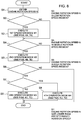
- FIG. 8 is a flowchart of a method for controlling the two-stage turbo system 1 according to an embodiment of the present invention.
- the method for controlling the two-stage turbo system 1 includes, as shown in FIG. 8 , a rotation speed acquisition step (S1) of obtaining the rotation speed of the engine 7 (S1), a region determination step (S2, S4, S6, S7) of determining the rotation speed region of the rotation speed of the engine 7, and a low rotation speed time control step (S3) that is performed if the rotation speed of the engine 7 is in the low rotation speed region (S3).
- the present method may further include a middle rotation speed time control step (S5), a first high rotation speed time control step (S8), and a second high rotation speed control step (S9).
- control device 6 controlling the valve device 5 as in the embodiment shown in FIGs. 1 to 7D .
- the control device 6 includes functional parts for executing each of the above steps.
- step S1 of FIG. 8 the control device 6 obtains the engine rotation speed N (rotation speed acquisition step). Further, after the step S1, the control device 6 determines the rotation speed region in which the rotation speed of the engine 7 is positioned through comparison, for instance, between the obtained engine rotation speed N and a threshold of the rotation speed (the above described first threshold, second threshold), and performs the above operation modes on the basis of the determination result.
- a threshold of the rotation speed the above described first threshold, second threshold
- step S2 the control device 6 determines whether the engine rotation speed N is in the low rotation speed region (region determination step). Then, if the engine rotation speed N is in the low rotation speed region, the control device 6 controls the valve device 5 to execute the first operation mode in step S 3 (low rotation speed time control step). That is, in the exhaust passage 9, a flow passage (above described exhaust gas flow passage I) capable of supplying exhaust gas discharged from the engine 7 to the first scroll passage Pa of the low-pressure stage turbine 3T via the high-pressure stage turbine 2T is formed (see FIGs. 6A and 7A ). Then, the process advances to the next step S4. Further, the process advances to the next step S4 also if the engine rotation speed N is not in the low rotation speed region in step S2.
- step S4 the control device 6 determines whether the engine rotation speed N is in the middle rotation speed region (region determination step). Then, if the engine rotation speed N is in the middle rotation speed region, the control device 6 controls the valve device 5 to execute the second operation mode M2 in step S5 (middle rotation speed time control step). That is, in the exhaust passage 9, two flow passages, namely, the above described exhaust gas flow passage I, and a flow passage (above described exhaust gas flow passage II) capable of supplying exhaust gas discharged from the engine 7 to the second scroll passage Pb of the low-pressure stage turbine 3T while bypassing the high-pressure stage turbine 2T are formed (see FIGs. 6B and 7B ). Then, the process advances to the next step S6. Further, the process advances to the next step S6 also if the engine rotation speed N is not in the middle rotation speed region in step S4.
- step S6 the control device 6 determines whether the engine rotation speed N is in the high rotation speed region (region determination step). Further, if the engine rotation speed N is in the high rotation speed region, in step S7, the control device 6 determines whether the engine rotation speed N is not lower than a predetermined rotation speed (region determination step). If the engine rotation speed N is lower than the predetermined rotation speed in step S7, the control device 6 controls the valve device 5 to execute the third operation mode M3 in step S8 (first high rotation speed time control step).
- two flow passages namely, the above described exhaust gas flow passage II, and a flow passage (above described exhaust gas flow passage III) capable of supplying exhaust gas discharged from the engine 7 to the first scroll passage Pa of the low-pressure stage turbine 3T without passing through the high-pressure stage turbine 2T are formed (see FIGs. 6C and 7C ). Then the flow of FIG. 8 is ended.
- step S9 second high rotation speed time control step. That is, in the exhaust passage 9, a flow passage (above described exhaust gas flow passage IV) capable of supplying exhaust gas discharged from the engine 7 to the low-pressure stage downstream passage 97 of the low-pressure stage turbine 3T without passing through either one of the high-pressure stage turbine 2T or the low-pressure stage turbine 3T is added to the flow passages (exhaust gas flow passage II and exhaust gas flow passage III) formed when the engine rotation speed is determined to be in the high rotation speed region, and thereby three flow passages are formed in total (see FIGs. 6D and 7D ). Then the flow of FIG. 8 is ended.
- a flow passage above described exhaust gas flow passage IV
Landscapes
- Engineering & Computer Science (AREA)
- Chemical & Material Sciences (AREA)
- Combustion & Propulsion (AREA)
- Mechanical Engineering (AREA)
- General Engineering & Computer Science (AREA)
- Supercharger (AREA)
Applications Claiming Priority (2)
| Application Number | Priority Date | Filing Date | Title |
|---|---|---|---|
| JP2016068503A JP6754596B2 (ja) | 2016-03-30 | 2016-03-30 | 2ステージターボシステムおよび2ステージターボシステムの制御方法 |
| PCT/JP2017/008570 WO2017169515A1 (ja) | 2016-03-30 | 2017-03-03 | 2ステージターボシステムおよび2ステージターボシステムの制御方法 |
Publications (3)
| Publication Number | Publication Date |
|---|---|
| EP3438428A1 true EP3438428A1 (de) | 2019-02-06 |
| EP3438428A4 EP3438428A4 (de) | 2019-10-09 |
| EP3438428B1 EP3438428B1 (de) | 2021-05-05 |
Family
ID=59964037
Family Applications (1)
| Application Number | Title | Priority Date | Filing Date |
|---|---|---|---|
| EP17774060.2A Active EP3438428B1 (de) | 2016-03-30 | 2017-03-03 | 2-stufiges turbosystem und verfahren zur steuerung eines 2-stufigen turbosystems |
Country Status (5)
| Country | Link |
|---|---|
| US (1) | US10787955B2 (de) |
| EP (1) | EP3438428B1 (de) |
| JP (1) | JP6754596B2 (de) |
| CN (1) | CN108713093B (de) |
| WO (1) | WO2017169515A1 (de) |
Families Citing this family (3)
| Publication number | Priority date | Publication date | Assignee | Title |
|---|---|---|---|---|
| EP3730758B1 (de) * | 2018-01-29 | 2022-04-20 | Mitsubishi Heavy Industries Engine & Turbocharger, Ltd. | Verbrennungsmotor mit lader |
| JP7259397B2 (ja) * | 2019-02-25 | 2023-04-18 | 株式会社Ihi | タービン |
| JP7151866B2 (ja) | 2019-03-06 | 2022-10-12 | 株式会社Ihi | タービン |
Family Cites Families (22)
| Publication number | Priority date | Publication date | Assignee | Title |
|---|---|---|---|---|
| GB2178111B (en) | 1985-07-17 | 1990-02-28 | Geoffrey Light Wilde | Improvements in or relating to a variable inlet for a radial turbine |
| EP0212834B1 (de) | 1985-07-17 | 1990-11-14 | Geoffrey Light Wilde | Variabler Einlass für eine Radialturbine |
| JPH01227803A (ja) | 1988-03-08 | 1989-09-12 | Honda Motor Co Ltd | 可変容量タービン |
| DE4242494C1 (en) * | 1992-12-16 | 1993-09-09 | Mercedes-Benz Aktiengesellschaft, 70327 Stuttgart, De | Adjustable flow-guide for engine exhaust turbocharger - has axially-adjustable annular insert in sectors forming different kinds of guide grilles supplied simultaneously by spiral passages |
| DE10212675B4 (de) * | 2002-03-22 | 2006-05-18 | Daimlerchrysler Ag | Abgasturbolader in einer Brennkraftmaschine |
| DE10222919B4 (de) | 2002-05-24 | 2007-12-20 | Man Nutzfahrzeuge Ag | Zweistufig aufgeladene Brennkraftmaschine |
| JP2005133665A (ja) * | 2003-10-31 | 2005-05-26 | Toyota Motor Corp | 複数の排気ガス供給ポートを有する排気タービン |
| US7644585B2 (en) * | 2004-08-31 | 2010-01-12 | The United States Of America As Represented By The Administrator Of The U.S. Environmental Protection Agency | Multi-stage turbocharging system with efficient bypass |
| CN101091041A (zh) | 2004-08-31 | 2007-12-19 | 美国环境保护署 | 具有有效旁路的多级涡轮增压系统 |
| DE202005022022U1 (de) | 2004-09-27 | 2012-05-31 | Borgwarner Inc. | Mehrstufiges Turboladesystem, das VTG-Turbinenstufe(n) benutzt |
| DE102005039756A1 (de) * | 2005-08-23 | 2007-03-01 | Robert Bosch Gmbh | Aufladeeinrichtung mit zweistufiger Niederdruckturbine |
| US7426831B2 (en) * | 2005-10-06 | 2008-09-23 | Borgwarner Inc. | Turbo charging system |
| DE102007034235A1 (de) * | 2007-07-23 | 2009-01-29 | Continental Automotive Gmbh | Strömungsgehäuse eines Turboladers |
| GB0717212D0 (en) | 2007-09-05 | 2007-10-17 | Cummins Turbo Tech Ltd | Multi-stage turbocharger system |
| JP2010190070A (ja) * | 2009-02-17 | 2010-09-02 | Toyota Motor Corp | 内燃機関システム制御装置 |
| JP5324961B2 (ja) * | 2009-02-27 | 2013-10-23 | 三菱重工業株式会社 | 内燃機関の過給システム |
| US10054037B2 (en) * | 2009-11-21 | 2018-08-21 | Cummins Turbo Technologies Limited | Multi-stage turbocharger system with bypass flowpaths and flow control valve |
| SE536089C2 (sv) | 2010-05-04 | 2013-04-30 | Alpraaz Ab | Turbinhus för överladdningsaggregat samt överladdningsaggregat för en förbränningsmotor innefattande ett sådant turbinhus |
| EP2466092A1 (de) | 2010-12-17 | 2012-06-20 | Perkins Engines Company Limited | Turboladersystem |
| WO2014140598A1 (en) * | 2013-03-15 | 2014-09-18 | Imperial Innovations Limited | Asymmetric double-entry turbine |
| US9103272B2 (en) | 2013-06-10 | 2015-08-11 | Ford Global Technologies, Llc | Method and system for binary flow turbine control |
| DE102014216820B4 (de) | 2013-09-19 | 2021-09-23 | Ford Global Technologies, Llc | Verfahren zum Betreiben einer aufgeladenen Brennkraftmaschine |
-
2016
- 2016-03-30 JP JP2016068503A patent/JP6754596B2/ja not_active Expired - Fee Related
-
2017
- 2017-03-03 EP EP17774060.2A patent/EP3438428B1/de active Active
- 2017-03-03 US US16/080,245 patent/US10787955B2/en not_active Expired - Fee Related
- 2017-03-03 CN CN201780013603.7A patent/CN108713093B/zh not_active Expired - Fee Related
- 2017-03-03 WO PCT/JP2017/008570 patent/WO2017169515A1/ja not_active Ceased
Also Published As
| Publication number | Publication date |
|---|---|
| US10787955B2 (en) | 2020-09-29 |
| CN108713093B (zh) | 2021-06-01 |
| EP3438428A4 (de) | 2019-10-09 |
| CN108713093A (zh) | 2018-10-26 |
| JP2017180286A (ja) | 2017-10-05 |
| US20190048789A1 (en) | 2019-02-14 |
| WO2017169515A1 (ja) | 2017-10-05 |
| JP6754596B2 (ja) | 2020-09-16 |
| EP3438428B1 (de) | 2021-05-05 |
Similar Documents
| Publication | Publication Date | Title |
|---|---|---|
| KR101390542B1 (ko) | 내연기관의 터보과급 시스템 | |
| US9828922B2 (en) | Supercharged internal combustion engine with exhaust-gas turbocharger and method for operating an internal combustion engine of said type | |
| US20090120087A1 (en) | Exhaust gas turbocharger in an internal combustion engine | |
| JP5556295B2 (ja) | 過給機付エンジンのegr装置 | |
| US10697377B2 (en) | Turbine supercharger and two-stage supercharging system | |
| US20170292381A1 (en) | Exhaust turbine for turbocharger | |
| JP2009167938A (ja) | 内燃機関用ターボ過給機 | |
| US20160238013A1 (en) | Compressor with Variable Compressor Inlet | |
| EP3438430B1 (de) | Turbolader, zweistufiges turbosystem und verfahren zur steuerung des zweistufigen turbosystems | |
| JP2012052508A (ja) | 可変過給機及び可変過給機の制御方法 | |
| EP3438428B1 (de) | 2-stufiges turbosystem und verfahren zur steuerung eines 2-stufigen turbosystems | |
| JP5596709B2 (ja) | タービン効率をコントロールするための方法および装置 | |
| US20180045101A1 (en) | A multi-stage exhaust turbocharger system | |
| WO2011108093A1 (ja) | 過給機を有する内燃機関の制御装置 | |
| JP2010053788A (ja) | シーケンシャルターボシステム | |
| US11629612B2 (en) | System for feeding operating gas to a drive of a motor vehicle | |
| US20190368414A1 (en) | Engine system and method using the same | |
| US20180023455A1 (en) | Multi-stage exhaust turbocharger system | |
| JP6443738B2 (ja) | 可変容量型過給機付きエンジン | |
| JP2016050567A (ja) | 内燃機関 | |
| KR20090129807A (ko) | 가변 구조 터보차져 | |
| KR20190005263A (ko) | 터보차저 | |
| KR20090102563A (ko) | 가변 구조 터보차져 | |
| WO2016181427A1 (ja) | 圧縮空気製造装置およびこれを備えるターボチャージャ並びに内燃機関 |
Legal Events
| Date | Code | Title | Description |
|---|---|---|---|
| STAA | Information on the status of an ep patent application or granted ep patent |
Free format text: STATUS: THE INTERNATIONAL PUBLICATION HAS BEEN MADE |
|
| PUAI | Public reference made under article 153(3) epc to a published international application that has entered the european phase |
Free format text: ORIGINAL CODE: 0009012 |
|
| STAA | Information on the status of an ep patent application or granted ep patent |
Free format text: STATUS: REQUEST FOR EXAMINATION WAS MADE |
|
| 17P | Request for examination filed |
Effective date: 20180827 |
|
| AK | Designated contracting states |
Kind code of ref document: A1 Designated state(s): AL AT BE BG CH CY CZ DE DK EE ES FI FR GB GR HR HU IE IS IT LI LT LU LV MC MK MT NL NO PL PT RO RS SE SI SK SM TR |
|
| AX | Request for extension of the european patent |
Extension state: BA ME |
|
| DAV | Request for validation of the european patent (deleted) | ||
| DAX | Request for extension of the european patent (deleted) | ||
| A4 | Supplementary search report drawn up and despatched |
Effective date: 20190909 |
|
| RIC1 | Information provided on ipc code assigned before grant |
Ipc: F02B 37/013 20060101ALI20190903BHEP Ipc: F02B 37/00 20060101AFI20190903BHEP Ipc: F02B 37/18 20060101ALI20190903BHEP Ipc: F02B 37/02 20060101ALI20190903BHEP |
|
| STAA | Information on the status of an ep patent application or granted ep patent |
Free format text: STATUS: EXAMINATION IS IN PROGRESS |
|
| 17Q | First examination report despatched |
Effective date: 20200528 |
|
| GRAP | Despatch of communication of intention to grant a patent |
Free format text: ORIGINAL CODE: EPIDOSNIGR1 |
|
| STAA | Information on the status of an ep patent application or granted ep patent |
Free format text: STATUS: GRANT OF PATENT IS INTENDED |
|
| INTG | Intention to grant announced |
Effective date: 20201123 |
|
| GRAS | Grant fee paid |
Free format text: ORIGINAL CODE: EPIDOSNIGR3 |
|
| GRAA | (expected) grant |
Free format text: ORIGINAL CODE: 0009210 |
|
| STAA | Information on the status of an ep patent application or granted ep patent |
Free format text: STATUS: THE PATENT HAS BEEN GRANTED |
|
| AK | Designated contracting states |
Kind code of ref document: B1 Designated state(s): AL AT BE BG CH CY CZ DE DK EE ES FI FR GB GR HR HU IE IS IT LI LT LU LV MC MK MT NL NO PL PT RO RS SE SI SK SM TR |
|
| REG | Reference to a national code |
Ref country code: GB Ref legal event code: FG4D |
|
| REG | Reference to a national code |
Ref country code: CH Ref legal event code: EP |
|
| REG | Reference to a national code |
Ref country code: AT Ref legal event code: REF Ref document number: 1390069 Country of ref document: AT Kind code of ref document: T Effective date: 20210515 |
|
| REG | Reference to a national code |
Ref country code: IE Ref legal event code: FG4D |
|
| REG | Reference to a national code |
Ref country code: DE Ref legal event code: R096 Ref document number: 602017038188 Country of ref document: DE |
|
| REG | Reference to a national code |
Ref country code: NL Ref legal event code: FP |
|
| REG | Reference to a national code |
Ref country code: LT Ref legal event code: MG9D |
|
| REG | Reference to a national code |
Ref country code: AT Ref legal event code: MK05 Ref document number: 1390069 Country of ref document: AT Kind code of ref document: T Effective date: 20210505 |
|
| PG25 | Lapsed in a contracting state [announced via postgrant information from national office to epo] |
Ref country code: FI Free format text: LAPSE BECAUSE OF FAILURE TO SUBMIT A TRANSLATION OF THE DESCRIPTION OR TO PAY THE FEE WITHIN THE PRESCRIBED TIME-LIMIT Effective date: 20210505 Ref country code: LT Free format text: LAPSE BECAUSE OF FAILURE TO SUBMIT A TRANSLATION OF THE DESCRIPTION OR TO PAY THE FEE WITHIN THE PRESCRIBED TIME-LIMIT Effective date: 20210505 Ref country code: HR Free format text: LAPSE BECAUSE OF FAILURE TO SUBMIT A TRANSLATION OF THE DESCRIPTION OR TO PAY THE FEE WITHIN THE PRESCRIBED TIME-LIMIT Effective date: 20210505 Ref country code: BG Free format text: LAPSE BECAUSE OF FAILURE TO SUBMIT A TRANSLATION OF THE DESCRIPTION OR TO PAY THE FEE WITHIN THE PRESCRIBED TIME-LIMIT Effective date: 20210805 Ref country code: AT Free format text: LAPSE BECAUSE OF FAILURE TO SUBMIT A TRANSLATION OF THE DESCRIPTION OR TO PAY THE FEE WITHIN THE PRESCRIBED TIME-LIMIT Effective date: 20210505 |
|
| PG25 | Lapsed in a contracting state [announced via postgrant information from national office to epo] |
Ref country code: IS Free format text: LAPSE BECAUSE OF FAILURE TO SUBMIT A TRANSLATION OF THE DESCRIPTION OR TO PAY THE FEE WITHIN THE PRESCRIBED TIME-LIMIT Effective date: 20210905 Ref country code: GR Free format text: LAPSE BECAUSE OF FAILURE TO SUBMIT A TRANSLATION OF THE DESCRIPTION OR TO PAY THE FEE WITHIN THE PRESCRIBED TIME-LIMIT Effective date: 20210806 Ref country code: LV Free format text: LAPSE BECAUSE OF FAILURE TO SUBMIT A TRANSLATION OF THE DESCRIPTION OR TO PAY THE FEE WITHIN THE PRESCRIBED TIME-LIMIT Effective date: 20210505 Ref country code: PL Free format text: LAPSE BECAUSE OF FAILURE TO SUBMIT A TRANSLATION OF THE DESCRIPTION OR TO PAY THE FEE WITHIN THE PRESCRIBED TIME-LIMIT Effective date: 20210505 Ref country code: PT Free format text: LAPSE BECAUSE OF FAILURE TO SUBMIT A TRANSLATION OF THE DESCRIPTION OR TO PAY THE FEE WITHIN THE PRESCRIBED TIME-LIMIT Effective date: 20210906 Ref country code: NO Free format text: LAPSE BECAUSE OF FAILURE TO SUBMIT A TRANSLATION OF THE DESCRIPTION OR TO PAY THE FEE WITHIN THE PRESCRIBED TIME-LIMIT Effective date: 20210805 Ref country code: RS Free format text: LAPSE BECAUSE OF FAILURE TO SUBMIT A TRANSLATION OF THE DESCRIPTION OR TO PAY THE FEE WITHIN THE PRESCRIBED TIME-LIMIT Effective date: 20210505 Ref country code: SE Free format text: LAPSE BECAUSE OF FAILURE TO SUBMIT A TRANSLATION OF THE DESCRIPTION OR TO PAY THE FEE WITHIN THE PRESCRIBED TIME-LIMIT Effective date: 20210505 |
|
| PG25 | Lapsed in a contracting state [announced via postgrant information from national office to epo] |
Ref country code: SK Free format text: LAPSE BECAUSE OF FAILURE TO SUBMIT A TRANSLATION OF THE DESCRIPTION OR TO PAY THE FEE WITHIN THE PRESCRIBED TIME-LIMIT Effective date: 20210505 Ref country code: SM Free format text: LAPSE BECAUSE OF FAILURE TO SUBMIT A TRANSLATION OF THE DESCRIPTION OR TO PAY THE FEE WITHIN THE PRESCRIBED TIME-LIMIT Effective date: 20210505 Ref country code: CZ Free format text: LAPSE BECAUSE OF FAILURE TO SUBMIT A TRANSLATION OF THE DESCRIPTION OR TO PAY THE FEE WITHIN THE PRESCRIBED TIME-LIMIT Effective date: 20210505 Ref country code: DK Free format text: LAPSE BECAUSE OF FAILURE TO SUBMIT A TRANSLATION OF THE DESCRIPTION OR TO PAY THE FEE WITHIN THE PRESCRIBED TIME-LIMIT Effective date: 20210505 Ref country code: EE Free format text: LAPSE BECAUSE OF FAILURE TO SUBMIT A TRANSLATION OF THE DESCRIPTION OR TO PAY THE FEE WITHIN THE PRESCRIBED TIME-LIMIT Effective date: 20210505 Ref country code: RO Free format text: LAPSE BECAUSE OF FAILURE TO SUBMIT A TRANSLATION OF THE DESCRIPTION OR TO PAY THE FEE WITHIN THE PRESCRIBED TIME-LIMIT Effective date: 20210505 Ref country code: ES Free format text: LAPSE BECAUSE OF FAILURE TO SUBMIT A TRANSLATION OF THE DESCRIPTION OR TO PAY THE FEE WITHIN THE PRESCRIBED TIME-LIMIT Effective date: 20210505 |
|
| REG | Reference to a national code |
Ref country code: DE Ref legal event code: R097 Ref document number: 602017038188 Country of ref document: DE |
|
| PLBE | No opposition filed within time limit |
Free format text: ORIGINAL CODE: 0009261 |
|
| STAA | Information on the status of an ep patent application or granted ep patent |
Free format text: STATUS: NO OPPOSITION FILED WITHIN TIME LIMIT |
|
| 26N | No opposition filed |
Effective date: 20220208 |
|
| PG25 | Lapsed in a contracting state [announced via postgrant information from national office to epo] |
Ref country code: IS Free format text: LAPSE BECAUSE OF FAILURE TO SUBMIT A TRANSLATION OF THE DESCRIPTION OR TO PAY THE FEE WITHIN THE PRESCRIBED TIME-LIMIT Effective date: 20210905 Ref country code: AL Free format text: LAPSE BECAUSE OF FAILURE TO SUBMIT A TRANSLATION OF THE DESCRIPTION OR TO PAY THE FEE WITHIN THE PRESCRIBED TIME-LIMIT Effective date: 20210505 |
|
| PG25 | Lapsed in a contracting state [announced via postgrant information from national office to epo] |
Ref country code: IT Free format text: LAPSE BECAUSE OF FAILURE TO SUBMIT A TRANSLATION OF THE DESCRIPTION OR TO PAY THE FEE WITHIN THE PRESCRIBED TIME-LIMIT Effective date: 20210505 |
|
| REG | Reference to a national code |
Ref country code: DE Ref legal event code: R119 Ref document number: 602017038188 Country of ref document: DE |
|
| PG25 | Lapsed in a contracting state [announced via postgrant information from national office to epo] |
Ref country code: MC Free format text: LAPSE BECAUSE OF FAILURE TO SUBMIT A TRANSLATION OF THE DESCRIPTION OR TO PAY THE FEE WITHIN THE PRESCRIBED TIME-LIMIT Effective date: 20210505 |
|
| REG | Reference to a national code |
Ref country code: CH Ref legal event code: PL |
|
| REG | Reference to a national code |
Ref country code: NL Ref legal event code: MM Effective date: 20220401 |
|
| GBPC | Gb: european patent ceased through non-payment of renewal fee |
Effective date: 20220303 |
|
| REG | Reference to a national code |
Ref country code: BE Ref legal event code: MM Effective date: 20220331 |
|
| PG25 | Lapsed in a contracting state [announced via postgrant information from national office to epo] |
Ref country code: NL Free format text: LAPSE BECAUSE OF NON-PAYMENT OF DUE FEES Effective date: 20220401 Ref country code: LU Free format text: LAPSE BECAUSE OF NON-PAYMENT OF DUE FEES Effective date: 20220303 Ref country code: LI Free format text: LAPSE BECAUSE OF NON-PAYMENT OF DUE FEES Effective date: 20220331 Ref country code: IE Free format text: LAPSE BECAUSE OF NON-PAYMENT OF DUE FEES Effective date: 20220303 Ref country code: GB Free format text: LAPSE BECAUSE OF NON-PAYMENT OF DUE FEES Effective date: 20220303 Ref country code: FR Free format text: LAPSE BECAUSE OF NON-PAYMENT OF DUE FEES Effective date: 20220331 Ref country code: DE Free format text: LAPSE BECAUSE OF NON-PAYMENT OF DUE FEES Effective date: 20221001 Ref country code: CH Free format text: LAPSE BECAUSE OF NON-PAYMENT OF DUE FEES Effective date: 20220331 |
|
| PG25 | Lapsed in a contracting state [announced via postgrant information from national office to epo] |
Ref country code: BE Free format text: LAPSE BECAUSE OF NON-PAYMENT OF DUE FEES Effective date: 20220331 |
|
| PG25 | Lapsed in a contracting state [announced via postgrant information from national office to epo] |
Ref country code: HU Free format text: LAPSE BECAUSE OF FAILURE TO SUBMIT A TRANSLATION OF THE DESCRIPTION OR TO PAY THE FEE WITHIN THE PRESCRIBED TIME-LIMIT; INVALID AB INITIO Effective date: 20170303 |
|
| PG25 | Lapsed in a contracting state [announced via postgrant information from national office to epo] |
Ref country code: MK Free format text: LAPSE BECAUSE OF FAILURE TO SUBMIT A TRANSLATION OF THE DESCRIPTION OR TO PAY THE FEE WITHIN THE PRESCRIBED TIME-LIMIT Effective date: 20210505 Ref country code: CY Free format text: LAPSE BECAUSE OF FAILURE TO SUBMIT A TRANSLATION OF THE DESCRIPTION OR TO PAY THE FEE WITHIN THE PRESCRIBED TIME-LIMIT Effective date: 20210505 |
|
| PG25 | Lapsed in a contracting state [announced via postgrant information from national office to epo] |
Ref country code: MT Free format text: LAPSE BECAUSE OF FAILURE TO SUBMIT A TRANSLATION OF THE DESCRIPTION OR TO PAY THE FEE WITHIN THE PRESCRIBED TIME-LIMIT Effective date: 20210505 |
|
| PG25 | Lapsed in a contracting state [announced via postgrant information from national office to epo] |
Ref country code: TR Free format text: LAPSE BECAUSE OF FAILURE TO SUBMIT A TRANSLATION OF THE DESCRIPTION OR TO PAY THE FEE WITHIN THE PRESCRIBED TIME-LIMIT Effective date: 20210505 |