EP3438517A1 - Système de lubrification doté d'un élément de transmission de signaux - Google Patents
Système de lubrification doté d'un élément de transmission de signaux Download PDFInfo
- Publication number
- EP3438517A1 EP3438517A1 EP18183180.1A EP18183180A EP3438517A1 EP 3438517 A1 EP3438517 A1 EP 3438517A1 EP 18183180 A EP18183180 A EP 18183180A EP 3438517 A1 EP3438517 A1 EP 3438517A1
- Authority
- EP
- European Patent Office
- Prior art keywords
- lubrication system
- lubricant
- lubrication
- signal transmission
- transmission device
- Prior art date
- Legal status (The legal status is an assumption and is not a legal conclusion. Google has not performed a legal analysis and makes no representation as to the accuracy of the status listed.)
- Withdrawn
Links
Images
Classifications
-
- F—MECHANICAL ENGINEERING; LIGHTING; HEATING; WEAPONS; BLASTING
- F16—ENGINEERING ELEMENTS AND UNITS; GENERAL MEASURES FOR PRODUCING AND MAINTAINING EFFECTIVE FUNCTIONING OF MACHINES OR INSTALLATIONS; THERMAL INSULATION IN GENERAL
- F16N—LUBRICATING
- F16N13/00—Lubricating-pumps
- F16N13/22—Lubricating-pumps with distributing equipment
-
- F—MECHANICAL ENGINEERING; LIGHTING; HEATING; WEAPONS; BLASTING
- F16—ENGINEERING ELEMENTS AND UNITS; GENERAL MEASURES FOR PRODUCING AND MAINTAINING EFFECTIVE FUNCTIONING OF MACHINES OR INSTALLATIONS; THERMAL INSULATION IN GENERAL
- F16N—LUBRICATING
- F16N7/00—Arrangements for supplying oil or unspecified lubricant from a stationary reservoir or the equivalent in or on the machine or member to be lubricated
- F16N7/38—Arrangements for supplying oil or unspecified lubricant from a stationary reservoir or the equivalent in or on the machine or member to be lubricated with a separate pump; Central lubrication systems
-
- F—MECHANICAL ENGINEERING; LIGHTING; HEATING; WEAPONS; BLASTING
- F16—ENGINEERING ELEMENTS AND UNITS; GENERAL MEASURES FOR PRODUCING AND MAINTAINING EFFECTIVE FUNCTIONING OF MACHINES OR INSTALLATIONS; THERMAL INSULATION IN GENERAL
- F16C—SHAFTS; FLEXIBLE SHAFTS; ELEMENTS OR CRANKSHAFT MECHANISMS; ROTARY BODIES OTHER THAN GEARING ELEMENTS; BEARINGS
- F16C33/00—Parts of bearings; Special methods for making bearings or parts thereof
- F16C33/30—Parts of ball or roller bearings
- F16C33/66—Special parts or details in view of lubrication
-
- F—MECHANICAL ENGINEERING; LIGHTING; HEATING; WEAPONS; BLASTING
- F16—ENGINEERING ELEMENTS AND UNITS; GENERAL MEASURES FOR PRODUCING AND MAINTAINING EFFECTIVE FUNCTIONING OF MACHINES OR INSTALLATIONS; THERMAL INSULATION IN GENERAL
- F16N—LUBRICATING
- F16N13/00—Lubricating-pumps
- F16N13/02—Lubricating-pumps with reciprocating piston
-
- F—MECHANICAL ENGINEERING; LIGHTING; HEATING; WEAPONS; BLASTING
- F16—ENGINEERING ELEMENTS AND UNITS; GENERAL MEASURES FOR PRODUCING AND MAINTAINING EFFECTIVE FUNCTIONING OF MACHINES OR INSTALLATIONS; THERMAL INSULATION IN GENERAL
- F16N—LUBRICATING
- F16N29/00—Special means in lubricating arrangements or systems providing for the indication or detection of undesired conditions; Use of devices responsive to conditions in lubricating arrangements or systems
- F16N29/02—Special means in lubricating arrangements or systems providing for the indication or detection of undesired conditions; Use of devices responsive to conditions in lubricating arrangements or systems for influencing the supply of lubricant
-
- F—MECHANICAL ENGINEERING; LIGHTING; HEATING; WEAPONS; BLASTING
- F16—ENGINEERING ELEMENTS AND UNITS; GENERAL MEASURES FOR PRODUCING AND MAINTAINING EFFECTIVE FUNCTIONING OF MACHINES OR INSTALLATIONS; THERMAL INSULATION IN GENERAL
- F16N—LUBRICATING
- F16N29/00—Special means in lubricating arrangements or systems providing for the indication or detection of undesired conditions; Use of devices responsive to conditions in lubricating arrangements or systems
- F16N29/04—Special means in lubricating arrangements or systems providing for the indication or detection of undesired conditions; Use of devices responsive to conditions in lubricating arrangements or systems enabling a warning to be given; enabling moving parts to be stopped
-
- F—MECHANICAL ENGINEERING; LIGHTING; HEATING; WEAPONS; BLASTING
- F16—ENGINEERING ELEMENTS AND UNITS; GENERAL MEASURES FOR PRODUCING AND MAINTAINING EFFECTIVE FUNCTIONING OF MACHINES OR INSTALLATIONS; THERMAL INSULATION IN GENERAL
- F16N—LUBRICATING
- F16N7/00—Arrangements for supplying oil or unspecified lubricant from a stationary reservoir or the equivalent in or on the machine or member to be lubricated
- F16N7/38—Arrangements for supplying oil or unspecified lubricant from a stationary reservoir or the equivalent in or on the machine or member to be lubricated with a separate pump; Central lubrication systems
- F16N7/385—Central lubrication systems
-
- G—PHYSICS
- G08—SIGNALLING
- G08C—TRANSMISSION SYSTEMS FOR MEASURED VALUES, CONTROL OR SIMILAR SIGNALS
- G08C17/00—Arrangements for transmitting signals characterised by the use of a wireless electrical link
-
- H—ELECTRICITY
- H01—ELECTRIC ELEMENTS
- H01F—MAGNETS; INDUCTANCES; TRANSFORMERS; SELECTION OF MATERIALS FOR THEIR MAGNETIC PROPERTIES
- H01F7/00—Magnets
- H01F7/06—Electromagnets; Actuators including electromagnets
-
- H—ELECTRICITY
- H02—GENERATION; CONVERSION OR DISTRIBUTION OF ELECTRIC POWER
- H02J—ELECTRIC POWER NETWORKS; CIRCUIT ARRANGEMENTS OR SYSTEMS FOR SUPPLYING OR DISTRIBUTING ELECTRIC POWER; SYSTEMS FOR STORING ELECTRIC ENERGY
- H02J7/00—Circuit arrangements for charging or discharging batteries or for supplying loads from batteries
-
- H—ELECTRICITY
- H02—GENERATION; CONVERSION OR DISTRIBUTION OF ELECTRIC POWER
- H02N—ELECTRIC MACHINES NOT OTHERWISE PROVIDED FOR
- H02N2/00—Electric machines in general using piezoelectric effect, electrostriction or magnetostriction
- H02N2/18—Electric machines in general using piezoelectric effect, electrostriction or magnetostriction producing electrical output from mechanical input, e.g. generators
-
- F—MECHANICAL ENGINEERING; LIGHTING; HEATING; WEAPONS; BLASTING
- F16—ENGINEERING ELEMENTS AND UNITS; GENERAL MEASURES FOR PRODUCING AND MAINTAINING EFFECTIVE FUNCTIONING OF MACHINES OR INSTALLATIONS; THERMAL INSULATION IN GENERAL
- F16N—LUBRICATING
- F16N2210/00—Applications
- F16N2210/14—Bearings
-
- F—MECHANICAL ENGINEERING; LIGHTING; HEATING; WEAPONS; BLASTING
- F16—ENGINEERING ELEMENTS AND UNITS; GENERAL MEASURES FOR PRODUCING AND MAINTAINING EFFECTIVE FUNCTIONING OF MACHINES OR INSTALLATIONS; THERMAL INSULATION IN GENERAL
- F16N—LUBRICATING
- F16N2230/00—Signal processing
-
- F—MECHANICAL ENGINEERING; LIGHTING; HEATING; WEAPONS; BLASTING
- F16—ENGINEERING ELEMENTS AND UNITS; GENERAL MEASURES FOR PRODUCING AND MAINTAINING EFFECTIVE FUNCTIONING OF MACHINES OR INSTALLATIONS; THERMAL INSULATION IN GENERAL
- F16N—LUBRICATING
- F16N2250/00—Measuring
-
- F—MECHANICAL ENGINEERING; LIGHTING; HEATING; WEAPONS; BLASTING
- F16—ENGINEERING ELEMENTS AND UNITS; GENERAL MEASURES FOR PRODUCING AND MAINTAINING EFFECTIVE FUNCTIONING OF MACHINES OR INSTALLATIONS; THERMAL INSULATION IN GENERAL
- F16N—LUBRICATING
- F16N2250/00—Measuring
- F16N2250/04—Pressure
-
- F—MECHANICAL ENGINEERING; LIGHTING; HEATING; WEAPONS; BLASTING
- F16—ENGINEERING ELEMENTS AND UNITS; GENERAL MEASURES FOR PRODUCING AND MAINTAINING EFFECTIVE FUNCTIONING OF MACHINES OR INSTALLATIONS; THERMAL INSULATION IN GENERAL
- F16N—LUBRICATING
- F16N2250/00—Measuring
- F16N2250/18—Level
-
- F—MECHANICAL ENGINEERING; LIGHTING; HEATING; WEAPONS; BLASTING
- F16—ENGINEERING ELEMENTS AND UNITS; GENERAL MEASURES FOR PRODUCING AND MAINTAINING EFFECTIVE FUNCTIONING OF MACHINES OR INSTALLATIONS; THERMAL INSULATION IN GENERAL
- F16N—LUBRICATING
- F16N2250/00—Measuring
- F16N2250/40—Flow
-
- F—MECHANICAL ENGINEERING; LIGHTING; HEATING; WEAPONS; BLASTING
- F16—ENGINEERING ELEMENTS AND UNITS; GENERAL MEASURES FOR PRODUCING AND MAINTAINING EFFECTIVE FUNCTIONING OF MACHINES OR INSTALLATIONS; THERMAL INSULATION IN GENERAL
- F16N—LUBRICATING
- F16N2260/00—Fail safe
- F16N2260/02—Indicating
-
- F—MECHANICAL ENGINEERING; LIGHTING; HEATING; WEAPONS; BLASTING
- F16—ENGINEERING ELEMENTS AND UNITS; GENERAL MEASURES FOR PRODUCING AND MAINTAINING EFFECTIVE FUNCTIONING OF MACHINES OR INSTALLATIONS; THERMAL INSULATION IN GENERAL
- F16N—LUBRICATING
- F16N2270/00—Controlling
- F16N2270/70—Supply
Definitions
- the present invention relates to a lubrication system for supplying at least one lubrication point with lubricant, wherein the lubrication system at least one lubricant delivery device that promotes the lubricant in the lubrication system to the lubrication point, a lubricant distribution device that distributes lubricant to the lubrication point and a control unit that at least the lubricant conveyor and / or the lubricant distribution device controls, has.
- Lubricating systems come in a variety of configurations to provide lubricant at a location to be lubricated.
- a lubrication system usually has a lubricant delivery device, such as a lubricant pump, and a lubricant line, via which lubricant is conveyed from the lubricant delivery device to the point to be lubricated.
- a lubricant distribution device is further provided, which distributes lubricant to the point to be lubricated, wherein the Schmierstoffverteilvoretti also often dosed and the amount dispensed.
- the lubrication system is usually controlled centrally via a control unit which monitors and controls at least the lubricant delivery device and the lubricant distribution device.
- the control unit is usually connected by means of cables with the lubrication system components, on the one hand to control the lubricant systems, as well as to receive signals from the lubrication system components.
- lubrication system monitoring devices or sensors in the lubrication system that monitor, test or detect the lubricant distribution or the lubricant flow. These lubrication system monitoring devices or sensors are also connected by cable to the control unit and transmit their monitoring variables to the control unit.
- a disadvantage of the conventional lubrication systems is that the wiring within the lubrication system is often very complex and sometimes disturbing. Furthermore, some lubrication system components or components thereof may not be connected to lubrication system monitors or sensors because cabling of these lubrication system monitors or sensors is not possible.
- Object of the present invention is therefore to provide a lubrication system in which the control unit of the lubrication system can also receive signals from components or components that are arranged in hard to reach places.
- a lubrication system for supplying at least one lubrication point with lubricant, wherein the lubrication system supplies at least one lubricant delivery device that conveys the lubricant in the lubrication system to the lubrication point, a lubricant distribution device that distributes lubricant to the lubrication point, and a control device that contains at least the lubricant delivery device and / or controls the lubricant distribution device comprises. Furthermore, the lubrication system has at least one lubrication system monitoring device which monitors a monitoring quantity of the lubrication system.
- the lubrication system further comprises at least one signal transmission device that is designed to wirelessly transmit a signal corresponding to the monitored variable provided by the lubrication system monitoring device to the control device and / or to transmit a functionally associated with the lubrication system associated device or to receive from him / her.
- the signal transmission device is preferably not only adapted to transmit signals, but also to receive.
- the term signal transmission device subsumes a device which both receives and transmits signals, or only transmits signals, or can only receive signals.
- a functionally associated with the lubrication system device may be, for example, a display unit that displays the signals of the lubrication system monitoring device. But it can also be any other component directly or indirectly associated with the lubrication system which, in particular, can directly or indirectly influence the functionality of the lubrication system. For example, a signal provided by a lubrication system monitor may be made visually accessible to an operator, who then makes manual adjustments to the lubrication system, for example.
- the device and / or the control unit can also be arranged in a central machine control room, which monitors and controls a multiplicity of machines and / or associated equipment items in addition to the lubrication system.
- this signal transmission can take place continuously and / or discontinuously.
- the signal transmission manner may be dependent on the lubrication system monitoring device.
- real-time sensors e.g. a temperature sensor, a continuous signal stream ready, while, for example, pressure limiting sensors only output a signal when a threshold is reached.
- the type of energization of the signal transmission unit and / or the lubrication system monitoring device can also be decisive for the signal transmission method.
- the signal transmission device continuously supplied with power for example by a central power grid or a battery
- a continuous signal transmission is easier to achieve, as in a power supply by means of self-sufficient power generation elements.
- These self-sufficient energy generating elements and / or a battery provide a limited amount of energy that is exhausted faster by a continuous signal transmission as in a discontinuous signal transmission.
- control device may be the lubricant delivery device and / or the lubricant distribution device on the basis of wirelessly transmitted signal directly.
- the control device may be the lubricant delivery device and / or the lubricant distribution device on the basis of wirelessly transmitted signal directly.
- the signal transmission device may be attached directly to a lubrication system component, such as the lubrication system monitor, or to the lubrication system component monitored by the lubrication system monitor, but it is also possible for the signal transmission device to be present as a standalone lubrication system component in the lubrication system.
- a lubrication system monitoring device can be used in hard to reach places, but still can transmit their monitoring variables to the control unit.
- the at least one signal transmission device is included in the lubricant delivery device and / or the lubricant distribution device and / or a further lubricant system component.
- the direct integration of the signal transmission device in the components of the lubrication system can be a very simple and fast signal transmission within the lubrication system.
- the signal transmission device itself can be permanently installed in the component of the lubrication system and benefits in this installation situation, for example, from a central power supply, which supplies the lubrication system component and thus the signal transmission device with energy.
- the incorporation into the lubrication system component itself enables the lubrication system monitoring device, which is also provided, for example, in the lubrication system component, to be directly wired to the signal transmission device so that signals are sent to or received from the lubrication system component via an interface only ,
- the lubrication system monitoring device further comprises at least one sensor which detects at least one monitoring variable of the lubrication system. It is particularly advantageous if the lubrication system monitoring device or the sensor has the at least one signal transmission device that transmits the signal that is associated with the detected monitoring variable wirelessly to the control unit. Especially sensors may be needed in hard to reach places in the lubrication system, where a wired connection with the control unit is often not possible. Because of the wireless signal transmission device, sensors can therefore also be arranged at points in the lubrication system that were previously inaccessible to a sensor arrangement, since no signal transmission capability from the sensor to the control unit was possible.
- the lubrication system monitoring device is for example a pressure switch, a level switch, a flow sensor, a piston sensor and / or a valve. Thanks to the wireless signal transmission, even with these elements, any positioning in the lubrication system is possible.
- the lubricant delivery device is a lubricant pump and / or the lubricant distribution device is an introduction distributor, a multi-line distributor, a progressive distributor, a quantity limitation unit, a quantity restriction unit, a lubricant metering unit and / or a valve.
- the lubricant delivery device is a lubricant pump and / or the lubricant distribution device is an introduction distributor, a multi-line distributor, a progressive distributor, a quantity limitation unit, a quantity restriction unit, a lubricant metering unit and / or a valve.
- other components may be provided in the lubrication system, and it is also possible that other than the above-mentioned examples function as a lubricant delivery device or Schmierstoffverteilvorraum.
- the lubrication system further comprises an energy supply device, which at least partially provides the energy for the signal transmission device and / or the lubrication system monitoring device.
- This energy supply device can be, for example, a battery, a central power supply and / or a power generation device that generates energy, for example, by means of inductance or via one or more piezoelectric elements. Since often the lubrication system components are electrically functioning and equipped with a power supply, the signal transmission device can be easily connected to this already existing power supply. If such a connection is difficult, either a battery can perform this task or energy can be generated directly on the signal transmission device, for example via induction or deformation energy.
- a component of the lubrication system and / or a lubricant line connecting the components of the lubrication system has at least one moving element, and the energy generating element cooperates with the moving element and generates the energy required by the signal transmission device.
- signal transmission devices can be arranged at locations that were previously inaccessible to a signal transmission facility.
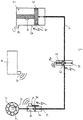
- FIG. 1 schematically shows a lubrication system 1 with a lubricant conveyor 2, which is connected to a lubricant line 4 to promote lubricant to a point to be lubricated 6, which is shown here as a bearing.
- a lubricant distribution device 8 is furthermore provided, which is arranged upstream of the bearing 6.
- the lubricant distribution device can be, for example, an introduction distributor or progressive distributor.
- a lubrication system monitoring device in the form of a sensor 10 is further provided on the lubricant line 4, which monitors, for example, a lubricant flow through the line 4 or its temperature or viscosity.
- the lubrication system monitoring device 10 is a pressure switch which measures the pressure of the lubricant transported in the lubricant line 4.
- the lubrication system 1 has a signal transmission device 14, by means of which, for example, a monitoring variable of the lubrication system monitoring device 10 can be transmitted to or received from a remote control device 18 or to a remote user.
- a signal can also be output by the control unit 18 which is received, for example, by the signal transmission device 14 of the lubricant distribution device 8 in order to control the quantity of lubricant to be delivered to the bearing 6.
- the lubrication system comprises further lubrication system monitoring device 11, 12, 13, so that the lubrication system 1 can also be controlled based on monitoring variables of lubrication system monitoring devices 11, 12, 13, which are arranged in hard to reach places.
- further signal transmission device 15, 16, 17 are provided in the lubrication system 1, which is designed to transmit a signal corresponding to that provided by the lubrication system monitoring device 11, 12, 13 wirelessly to the control unit 18 or to receive from it.
- a lubrication system monitoring device 13 or a signal transmission device 17 can also be arranged at the point to be lubricated.
- the lubrication system monitoring device 10, 11, 12, 13 and the signal transmission device 14, 15, 16, 17, 19 may be separate elements, but it is also possible that the lubrication system monitoring device 10, 11, 12, 13 and the signal transmission device 14, 15, 16 , 17, 19 are integrally formed.
- the signal transmission device 14, 15, 16, 17, 19 may be mounted directly on the lubrication system component 2, 4, 6, 8, 10, 18 monitored by the lubrication system monitoring device 10, 11, 12, 13, however, it is also possible that the Signal transmission device 14, 15, 16, 17, 19 is present as an independent lubrication system component in the lubrication system 1.
- the signal transmission device 14, 15, 16, 17, 19 is integrated directly into the components of the lubrication system 1, a very simple and fast signal transmission within the lubrication system 1 can take place.
- the signal transmission device 14, 15, 16, 17, 19 itself can be permanently installed in the component of the lubrication system 1 and benefits in this installation situation, for example, from a central power supply (not shown), the lubricating system component 2, 4, 6, 8, 10 , 18 and thus also the signal transmission device 14, 15, 16, 17, 19 supplied with energy.
- the incorporation into the lubrication system component 2, 4, 6, 8, 10, 18 itself enables the lubrication system monitoring device 10, 11, 12, 13, which is also provided, for example, in the lubrication system component 2, 4, 6, 8, 10, 18 , directly wired to the signal transmission device 14, 15, 16, 17, 19 can communicate, so that sent from the lubrication system component 2, 4, 6, 8, 10, 18 only via an interface signals to the control unit 18 and received by him ,
- the lubricant delivery device 2 the lubricant distribution device 8 and the sensor unit 10 on pistons 22, 23, 24, which provide for a lubricant distribution or -zuflop.
- These moving pistons 22, 23, 24 represent by way of example moving elements.
- the moving elements, in this case the pistons 22, 23, 24, continue to cooperate with energy generating elements 26, 27, 28, 29, wherein schematically on the lubricant distribution element 8 an inductive element 28 is arranged, while on the lubricant conveyor 2 and the sensor 10 piezo elements 26, 27 is provided.
- the components 2, 4, 8, 10 of the lubrication system may not only have a kind of power generating element, but it is also possible, as shown for example in the lubricant conveyor 2, to provide different energy generating elements 26, 29 on one component.
- an inductive energy generating element 29 can still be provided on the lubricant conveying device 2.
- These energy generating elements act in a known manner, wherein the piezoelectric elements gain electrical energy from a deformation of the element, while the inductive elements generate current via two mutually moving coils. These energy generating elements interact with the moving elements to produce energy provided in the lubricating system 1 for use. The energy production is illustrated by means of the symbol for electricity.
- This energy may be provided, for example, to the lubrication system monitors and / or signal transmission devices.
- At least one energy storage unit may be provided in the lubricating system 1, which cooperates with the energy generating elements to store energy for a later or high-energy application.
- an emergency power supply for an engine (not shown) of the lubricant delivery device 2 can be provided via the stored energy.
- the energy transfer between energy storage unit and energy consumers can be done for example by means of a wiring.
- a lubrication system can be provided with the lubrication system according to the invention, the individual and often difficult to access components can be equipped with lubrication system monitoring devices without having to be cabled to the control unit.
- Wireless signal transmission in the system can provide a lubrication system that can be more easily and accurately monitored. Since the signal transmission devices and / or the lubrication system monitoring devices only consume relatively little energy, it is also possible to use energy generating elements, such as piezo elements and / or induction elements, to directly generate the required energy itself.
Landscapes
- Engineering & Computer Science (AREA)
- General Engineering & Computer Science (AREA)
- Mechanical Engineering (AREA)
- Physics & Mathematics (AREA)
- Electromagnetism (AREA)
- Power Engineering (AREA)
- Computer Networks & Wireless Communication (AREA)
- General Physics & Mathematics (AREA)
- Arrangements For Transmission Of Measured Signals (AREA)
- General Details Of Gearings (AREA)
Applications Claiming Priority (1)
| Application Number | Priority Date | Filing Date | Title |
|---|---|---|---|
| DE102017213589.1A DE102017213589A1 (de) | 2017-08-04 | 2017-08-04 | Schmiersystem mit einem Signalübertragungselement |
Publications (1)
| Publication Number | Publication Date |
|---|---|
| EP3438517A1 true EP3438517A1 (fr) | 2019-02-06 |
Family
ID=62948022
Family Applications (1)
| Application Number | Title | Priority Date | Filing Date |
|---|---|---|---|
| EP18183180.1A Withdrawn EP3438517A1 (fr) | 2017-08-04 | 2018-07-12 | Système de lubrification doté d'un élément de transmission de signaux |
Country Status (4)
| Country | Link |
|---|---|
| US (1) | US20190040997A1 (fr) |
| EP (1) | EP3438517A1 (fr) |
| CN (1) | CN109386717A (fr) |
| DE (1) | DE102017213589A1 (fr) |
Families Citing this family (12)
| Publication number | Priority date | Publication date | Assignee | Title |
|---|---|---|---|---|
| DE102017213588A1 (de) * | 2017-08-04 | 2019-02-07 | Skf Lubrication Systems Germany Gmbh | Schmiersystem mit einem Energieerzeugungselement |
| CN110486613A (zh) * | 2019-09-07 | 2019-11-22 | 江苏中科朗润智能科技有限公司 | 分配器在线动作实时压力监测系统 |
| CN110513592A (zh) * | 2019-09-25 | 2019-11-29 | 江苏中科朗润智能科技有限公司 | 一种可自调供油压力的润滑系统 |
| DE102019219996A1 (de) * | 2019-12-18 | 2021-06-24 | Aktiebolaget Skf | Schmiernippeleinheit mit integriertem Schmiermitteldurchflussmesser |
| EP4176197A4 (fr) * | 2020-07-01 | 2024-07-03 | GB IP Holdings Pty Ltd | Dispositif, système et procédé de distribution de lubrifiant |
| CN111734942B (zh) * | 2020-07-06 | 2022-03-08 | 南通航海机械集团有限公司 | 一种船舶滑油系统恒流恒压控制装置及其控制方法 |
| DE102021204619A1 (de) * | 2021-05-06 | 2022-11-10 | Skf Lubrication Systems Germany Gmbh | Schmiersystem |
| DE102021204617A1 (de) * | 2021-05-06 | 2022-11-10 | Skf Lubrication Systems Germany Gmbh | Schmiersystem |
| CN114165716B (zh) * | 2021-11-18 | 2023-05-26 | 山东科技大学 | 一种润滑脂加注系统及其加注量监测方法 |
| WO2023115118A1 (fr) * | 2021-12-23 | 2023-06-29 | Gb Ip Holdings Pty Ltd | Dispositif, système et procédé de distribution de lubrifiant |
| US12352387B2 (en) * | 2023-04-12 | 2025-07-08 | Danny Rasdon | Bearing greasing assembly |
| DE102023113277A1 (de) * | 2023-05-22 | 2024-11-28 | Krones Aktiengesellschaft | Schmierstoffversorgung in einer technischen Anlage |
Citations (10)
| Publication number | Priority date | Publication date | Assignee | Title |
|---|---|---|---|---|
| EP1250550A2 (fr) * | 2000-01-27 | 2002-10-23 | SKF Engineering & Research Centre B.V. | Maintenance intelligente d'un roulement |
| US20040250623A1 (en) * | 2003-04-03 | 2004-12-16 | Steve Walker | Method and device for sensing health and condition of a bearing through the lubrication port of a machine |
| EP2101102A2 (fr) * | 2008-03-14 | 2009-09-16 | Lincoln GmbH | Unité intelligente de surveillance de la pression finale |
| US20130015019A1 (en) * | 2010-04-01 | 2013-01-17 | Jarno Kuvaja | Advanced lubrication system |
| US20130183138A1 (en) * | 2012-01-17 | 2013-07-18 | General Electric Company | Dual temperature oil control system and method for a wind turbine gearbox |
| EP2685149A1 (fr) * | 2012-07-11 | 2014-01-15 | SMS Meer GmbH | Dispositif de lubrification pour l'alimentation d'une pièce en lubrifiant |
| EP2952759A1 (fr) * | 2014-06-05 | 2015-12-09 | Aktiebolaget SKF | Palier à roulement et ensemble de capteur comprenant celui-ci |
| WO2016176308A1 (fr) * | 2015-04-29 | 2016-11-03 | Graco Minnesota Inc. | Injecteur de lubrification avec récupération d'énergie |
| DE102018118810A1 (de) * | 2017-08-04 | 2019-02-07 | GM Global Technology Operations LLC | Verfahren zur diagnose eines schmiersystems eines motors |
| DE102017125307A1 (de) * | 2017-10-27 | 2019-05-02 | Baier & Köppel GmbH & Co. KG | Verfahren zum Steuern einer Zentralschmieranlage, Computerlesbares Speichermedium, Zentralschmieranlage und System |
Family Cites Families (22)
| Publication number | Priority date | Publication date | Assignee | Title |
|---|---|---|---|---|
| US2667235A (en) * | 1947-04-29 | 1954-01-26 | Tecalemit Ltd | Liquid or lubricant distribution system |
| US4893697A (en) * | 1988-12-05 | 1990-01-16 | Watts Fluidair Div. Of Robert Shaw Controls Company | Injection lubricator with pulse counter |
| US5823295A (en) * | 1996-03-29 | 1998-10-20 | Caterpillar Inc. | Lubrication control system for a work machine |
| US6535135B1 (en) * | 2000-06-23 | 2003-03-18 | The Timken Company | Bearing with wireless self-powered sensor unit |
| US20070137936A1 (en) * | 2004-01-09 | 2007-06-21 | Jfe Steel Corporation | Lubricant feed state monitoring sensor and lubricant feed state monitoring device |
| US7806235B1 (en) * | 2006-10-04 | 2010-10-05 | Curtis Roys | Environmental compressor protection assembly |
| US9314261B2 (en) * | 2007-12-03 | 2016-04-19 | Covidien Ag | Battery-powered hand-held ultrasonic surgical cautery cutting device |
| US8201707B2 (en) * | 2009-02-27 | 2012-06-19 | Gotohti.Com Inc | Manual fluid dispenser with discharge measurement |
| CA3042643C (fr) * | 2010-04-15 | 2023-01-24 | Michael A. Webb | Systeme d'exploitation d'un mecanisme de declenchement d'une porte electrique a l'aide d'un dispositif recoltant l'energie piezoelectrique |
| US9022177B2 (en) * | 2010-11-29 | 2015-05-05 | Lincoln Industrial Corporation | Pump having stepper motor and overdrive control |
| ITMI20120288A1 (it) * | 2012-02-27 | 2013-08-28 | Dropsa Spa | Dispositivo di lubrificazione con misuratore di portata |
| US10111588B2 (en) * | 2012-03-29 | 2018-10-30 | Senseonics, Incorporated | Analyte sensor transceiver configured to provide tactile, visual, and/or aural feedback |
| CN102748577B (zh) * | 2012-07-11 | 2015-01-07 | 华锐风电科技(集团)股份有限公司 | 一种风力发电机组的润滑方法和润滑系统 |
| US9151444B2 (en) * | 2012-10-01 | 2015-10-06 | FD Johnson Company | Dual-series feeder lubrication system |
| CA2919049A1 (fr) * | 2013-08-07 | 2015-02-12 | Lincoln Industrial Corporation | Systeme de lubrification et dispositif de commande |
| CN105452621B (zh) * | 2013-08-07 | 2018-09-18 | 格雷索明尼苏达有限公司 | 一种润滑系统以及用于润滑剂储存器的入口截止组件 |
| US9618155B2 (en) * | 2013-12-19 | 2017-04-11 | Lincoln Industrial Corporation | Apparatus and method for controlling a lubrication unit using flow rate feedback |
| US9339714B2 (en) * | 2014-05-20 | 2016-05-17 | Arccos Golf Llc | System and method for monitoring performance characteristics associated with user activities involving swinging instruments |
| US9917460B2 (en) * | 2014-12-09 | 2018-03-13 | Briggs & Stratton Corporation | Lithium ion battery pack for outdoor power equipment |
| US10013825B2 (en) * | 2015-03-03 | 2018-07-03 | Acsys Ip Holding, Inc. | Systems and methods for redundant access control systems based on mobile devices |
| DE102016224587A1 (de) * | 2016-12-09 | 2018-06-14 | Adidas Ag | Nachrichtenübermittlungseinheit für Kleidungsstücke und Sportausrüstung |
| DE102017213588A1 (de) * | 2017-08-04 | 2019-02-07 | Skf Lubrication Systems Germany Gmbh | Schmiersystem mit einem Energieerzeugungselement |
-
2017
- 2017-08-04 DE DE102017213589.1A patent/DE102017213589A1/de not_active Withdrawn
-
2018
- 2018-06-27 CN CN201810677968.6A patent/CN109386717A/zh active Pending
- 2018-07-05 US US16/027,418 patent/US20190040997A1/en not_active Abandoned
- 2018-07-12 EP EP18183180.1A patent/EP3438517A1/fr not_active Withdrawn
Patent Citations (10)
| Publication number | Priority date | Publication date | Assignee | Title |
|---|---|---|---|---|
| EP1250550A2 (fr) * | 2000-01-27 | 2002-10-23 | SKF Engineering & Research Centre B.V. | Maintenance intelligente d'un roulement |
| US20040250623A1 (en) * | 2003-04-03 | 2004-12-16 | Steve Walker | Method and device for sensing health and condition of a bearing through the lubrication port of a machine |
| EP2101102A2 (fr) * | 2008-03-14 | 2009-09-16 | Lincoln GmbH | Unité intelligente de surveillance de la pression finale |
| US20130015019A1 (en) * | 2010-04-01 | 2013-01-17 | Jarno Kuvaja | Advanced lubrication system |
| US20130183138A1 (en) * | 2012-01-17 | 2013-07-18 | General Electric Company | Dual temperature oil control system and method for a wind turbine gearbox |
| EP2685149A1 (fr) * | 2012-07-11 | 2014-01-15 | SMS Meer GmbH | Dispositif de lubrification pour l'alimentation d'une pièce en lubrifiant |
| EP2952759A1 (fr) * | 2014-06-05 | 2015-12-09 | Aktiebolaget SKF | Palier à roulement et ensemble de capteur comprenant celui-ci |
| WO2016176308A1 (fr) * | 2015-04-29 | 2016-11-03 | Graco Minnesota Inc. | Injecteur de lubrification avec récupération d'énergie |
| DE102018118810A1 (de) * | 2017-08-04 | 2019-02-07 | GM Global Technology Operations LLC | Verfahren zur diagnose eines schmiersystems eines motors |
| DE102017125307A1 (de) * | 2017-10-27 | 2019-05-02 | Baier & Köppel GmbH & Co. KG | Verfahren zum Steuern einer Zentralschmieranlage, Computerlesbares Speichermedium, Zentralschmieranlage und System |
Also Published As
| Publication number | Publication date |
|---|---|
| DE102017213589A1 (de) | 2019-02-07 |
| CN109386717A (zh) | 2019-02-26 |
| US20190040997A1 (en) | 2019-02-07 |
Similar Documents
| Publication | Publication Date | Title |
|---|---|---|
| EP3438517A1 (fr) | Système de lubrification doté d'un élément de transmission de signaux | |
| DE102008014448B4 (de) | Intelligente Enddruckwächtereinheit | |
| DE102014118571A1 (de) | Vorrichtung und Verfahren zum Steuern einer Schmiereinheit mit Durchflussratenrückkopplung | |
| EP3126733B1 (fr) | Injecteur de lubrifiant | |
| DE102012217452A1 (de) | Schmierstoffverteiler für die Abgabe von Schmierstoff an mindestens eine Schmierstelle sowie Verfahren zum Betrieb desselben | |
| DE102017200481A1 (de) | Schmierstoffverteilsystem und Verfahren zu seinem Betrieb | |
| EP3438518B1 (fr) | Système de lubrification doté d'un élément de production d'énergie | |
| EP3516218A1 (fr) | Système de compresseur pour véhicule utilitaire | |
| DE19757546A1 (de) | Verfahren zur zentralen Steuerung und/oder Regelung der Schmierung zumindest einer Maschine | |
| EP3593029A1 (fr) | Pompe et système de lubrification | |
| EP3078112A1 (fr) | Actionneur comprenant un capteur de position | |
| DE102007033539A1 (de) | Verfahren zur Schmierung mehrerer Schmierstellen | |
| WO1998037332A1 (fr) | Systeme de traitement d'air sous pression | |
| DE102018101772B4 (de) | Schmierstoffverteileranordnung | |
| DE202017104672U1 (de) | Schmiersystem mit einem Signalübertragungselement | |
| EP2401514B1 (fr) | Soupape a regulation proportionnelle pour utilisations pneumatiques | |
| EP1702807A1 (fr) | Procédé et dispositif d'alimentation en tension continue comprenant plusieurs générateurs connectés en parallèle | |
| DE102018110161A1 (de) | Schmiersystem | |
| EP2880355A1 (fr) | Procédé permettant de faire fonctionner un système de lubrification centralisée, et système de lubrification centralisée | |
| EP2679975A2 (fr) | Dispositif et procédé de détection d'une fissure dans une conduite de fluide | |
| DE202017100160U1 (de) | Schmierstoffverteilsystem | |
| DE202017104671U1 (de) | Schmiersystem mit einem Energieerzeugungselement | |
| DE202011107955U1 (de) | Elektrohydraulischer Stellantrieb | |
| EP3299691A1 (fr) | Système de distribution de lubrifiant | |
| DE102019116126A1 (de) | Vorrichtung zur Anzeige des Betriebszustands von elektrischen Geräten |
Legal Events
| Date | Code | Title | Description |
|---|---|---|---|
| PUAI | Public reference made under article 153(3) epc to a published international application that has entered the european phase |
Free format text: ORIGINAL CODE: 0009012 |
|
| STAA | Information on the status of an ep patent application or granted ep patent |
Free format text: STATUS: THE APPLICATION HAS BEEN PUBLISHED |
|
| AK | Designated contracting states |
Kind code of ref document: A1 Designated state(s): AL AT BE BG CH CY CZ DE DK EE ES FI FR GB GR HR HU IE IS IT LI LT LU LV MC MK MT NL NO PL PT RO RS SE SI SK SM TR |
|
| AX | Request for extension of the european patent |
Extension state: BA ME |
|
| STAA | Information on the status of an ep patent application or granted ep patent |
Free format text: STATUS: REQUEST FOR EXAMINATION WAS MADE |
|
| 17P | Request for examination filed |
Effective date: 20190410 |
|
| RBV | Designated contracting states (corrected) |
Designated state(s): AL AT BE BG CH CY CZ DE DK EE ES FI FR GB GR HR HU IE IS IT LI LT LU LV MC MK MT NL NO PL PT RO RS SE SI SK SM TR |
|
| STAA | Information on the status of an ep patent application or granted ep patent |
Free format text: STATUS: EXAMINATION IS IN PROGRESS |
|
| 17Q | First examination report despatched |
Effective date: 20201014 |
|
| GRAP | Despatch of communication of intention to grant a patent |
Free format text: ORIGINAL CODE: EPIDOSNIGR1 |
|
| STAA | Information on the status of an ep patent application or granted ep patent |
Free format text: STATUS: GRANT OF PATENT IS INTENDED |
|
| INTG | Intention to grant announced |
Effective date: 20230320 |
|
| GRAS | Grant fee paid |
Free format text: ORIGINAL CODE: EPIDOSNIGR3 |
|
| P01 | Opt-out of the competence of the unified patent court (upc) registered |
Effective date: 20230605 |
|
| STAA | Information on the status of an ep patent application or granted ep patent |
Free format text: STATUS: THE APPLICATION IS DEEMED TO BE WITHDRAWN |
|
| 18D | Application deemed to be withdrawn |
Effective date: 20240201 |