EP3438531A1 - Kohledüse mit strömungsverengung - Google Patents
Kohledüse mit strömungsverengung Download PDFInfo
- Publication number
- EP3438531A1 EP3438531A1 EP17184058.0A EP17184058A EP3438531A1 EP 3438531 A1 EP3438531 A1 EP 3438531A1 EP 17184058 A EP17184058 A EP 17184058A EP 3438531 A1 EP3438531 A1 EP 3438531A1
- Authority
- EP
- European Patent Office
- Prior art keywords
- flow
- nozzle
- section
- outlet opening
- constriction
- Prior art date
- Legal status (The legal status is an assumption and is not a legal conclusion. Google has not performed a legal analysis and makes no representation as to the accuracy of the status listed.)
- Granted
Links
Images


Classifications
-
- F—MECHANICAL ENGINEERING; LIGHTING; HEATING; WEAPONS; BLASTING
- F23—COMBUSTION APPARATUS; COMBUSTION PROCESSES
- F23C—METHODS OR APPARATUS FOR COMBUSTION USING FLUID FUEL OR SOLID FUEL SUSPENDED IN A CARRIER GAS OR AIR
- F23C1/00—Combustion apparatus specially adapted for combustion of two or more kinds of fuel simultaneously or alternately, at least one kind of fuel being either a fluid fuel or a solid fuel suspended in a carrier gas or air
-
- F—MECHANICAL ENGINEERING; LIGHTING; HEATING; WEAPONS; BLASTING
- F23—COMBUSTION APPARATUS; COMBUSTION PROCESSES
- F23D—BURNERS
- F23D1/00—Burners for combustion of pulverulent fuel
-
- F—MECHANICAL ENGINEERING; LIGHTING; HEATING; WEAPONS; BLASTING
- F23—COMBUSTION APPARATUS; COMBUSTION PROCESSES
- F23C—METHODS OR APPARATUS FOR COMBUSTION USING FLUID FUEL OR SOLID FUEL SUSPENDED IN A CARRIER GAS OR AIR
- F23C13/00—Apparatus in which combustion takes place in the presence of catalytic material
- F23C13/06—Apparatus in which combustion takes place in the presence of catalytic material in which non-catalytic combustion takes place in addition to catalytic combustion, e.g. downstream of a catalytic element
-
- F—MECHANICAL ENGINEERING; LIGHTING; HEATING; WEAPONS; BLASTING
- F23—COMBUSTION APPARATUS; COMBUSTION PROCESSES
- F23C—METHODS OR APPARATUS FOR COMBUSTION USING FLUID FUEL OR SOLID FUEL SUSPENDED IN A CARRIER GAS OR AIR
- F23C2900/00—Special features of, or arrangements for combustion apparatus using fluid fuels or solid fuels suspended in air; Combustion processes therefor
- F23C2900/03005—Burners with an internal combustion chamber, e.g. for obtaining an increased heat release, a high speed jet flame or being used for starting the combustion
-
- F—MECHANICAL ENGINEERING; LIGHTING; HEATING; WEAPONS; BLASTING
- F23—COMBUSTION APPARATUS; COMBUSTION PROCESSES
- F23D—BURNERS
- F23D2201/00—Burners adapted for particulate solid or pulverulent fuels
- F23D2201/20—Fuel flow guiding devices
Definitions
- the present invention relates to a pulverized solid fuel, in particular coal, nozzle, that can be applied in a burner for burning pulverized coal, wherein the nozzle is designed in a manner which minimizes the formation of oxides of nitrogen in the burning process.
- powdered solid fuel typically coal
- this stream of air typically being referred to as primary air.
- the stream of air transports the pulverized coal and also provides at least a part of the oxygen needed for burning the coal.
- burners are typically used in furnaces or in boilers that create steam for various applications, such as creating electricity.
- the pulverized solid fuel, in particular coal, nozzle according to the current invention is a nozzle for solid fuel injection comprising an inlet opening for receiving a stream of a coal/air mixture and an outlet opening for discharging said stream into a burner, wherein the inlet opening and the outlet opening are fluidically connected by a flow section, wherein a flow cross section of the flow section is varying along a flow direction of the coal/air mixture and wherein the flow section comprises a flow constriction with a, preferentially globally, minimal flow cross section, characterized in that the flow constriction is fluidically located between the inlet opening and the outlet opening and in that the flow section has a flow cross section that increases from the flow constriction to the outlet opening.
- the flow section has a flow cross section that continuously increases for at least 50% of the extension of the flow section between the flow construction and outlet opening, in particular continuously increases for at least 60% of the extension of the flow section between the flow construction and outlet opening, in particular continuously increases for at least 80% of the extension of the flow section between the flow construction and outlet opening.
- the part of the flow section with the flow cross section that continuously increases is one uninterrupted part of the flow section.
- the flow section has a flow cross section that continuously increases over the entire extension of the flow section between the flow construction and outlet opening.
- the mixture of pulverized coal and air is blown into the Inlet opening of the nozzle and then flows in the flow direction along the flow section.
- the airstream is at its maximum flow speed.
- the stream of a coal/air mixture has passed the flow constriction its flow speed decreases due to the increase in flow cross section. This decrease in flow speed allows flame propagation into the nozzle. Therefore during operation of the nozzle the flame front is located within the nozzle which offers advantageous burning conditions for volatile matter in the fuel.
- the coal can ignite in a fuel rich environment and volatile matter in the fuel can be burned off such that a chemistry can be produced that reduces NOx that is produced via the later stages of the combustion.
- the flow section comprises a first expansion section and a second expansion section fluidically located between the flow constriction and the outlet opening, wherein the rate of change of the flow cross section of the first expansion section is higher than the rate of change of the flow cross section of the second expansion section.
- the described embodiment with the two expansion sections offers preferable flow characteristic such that the flame front is located within the nozzle but kept from propagating beyond the flow constriction.
- the first expansion section is arranged before the second expansion section in flow direction, preferably wherein the first expansion section is abutting the second expansion section.
- the flow cross section of the first expansion section and/or the second expansion section increases proportionally to the square of the respective extend in flow direction of the first expansion section and/or the second expansion. This is for example achieved if the respective expansion section is of circular cross-section and the diameter of this cross section increases linearly with the extent in flow direction.
- the flow cross section of the flow section is at least locally, preferentially along its entire length, of circular shape.
- the nozzle can be easily manufactured while the circular shape of the cross section is beneficial for the flow characteristics and especially the increase in flow cross section in combination with a circular shape of the cross section needs to beneficial flow characteristics that improve the flame propagation into the nozzle.
- an igniter is located in the flow section of the nozzle, preferentially between the flow constriction and the outlet opening.
- the wall of the flow section of the nozzle between the flow constriction and the outlet opening is at least locally, preferentially along its entire extend in flow direction, coated with a coating that comprises a catalyst, suitable for catalyzing the reaction of coal with oxygen.
- a coating that comprises a catalyst suitable for catalyzing the reaction of coal with oxygen.
- the nozzle comprises cooling means, wherein the cooling means are preferentially arranged in flow direction at least also between the flow constriction and the outlet opening.
- the cooling means are preferentially arranged in flow direction at least also between the flow constriction and the outlet opening.
- the cooling means comprise a fluid, in particular liquid, coolant jacket, preferentially wherein the coolant jacket surrounds the wall of the flow section at least also between the flow constriction and the outlet opening and/or wherein the coolant jacket surrounds the wall of the flow section before and after the flow constriction and/or wherein the coolant jacket extends in flow direction from before the flow constriction to the outlet opening.
- a coolant jacket allows surrounding the components to be cooled with the fluid coolant.
- the coolant jacket is designed to accommodate a liquid coolant.
- the use of a liquid coolant offers the benefit of a high cooling rate due to the generally high specific heat capacity of liquids.
- Such a liquid coolant can be water which offers the benefit of low costs, universal availability and high specific heat capacity.
- the coolant jacket has a coolant flow direction opposite to the flow direction of the stream of coal/air mixture.
- the nozzle comprises at least one coolant pipe with an inlet near the inlet opening of the nozzle and an outlet into the coolant jacket, wherein the outlet is preferably located near the outlet opening of the nozzle.
- the coolant can be introduced into the coolant pipe near the inlet opening where the temperature is within reasonable boundaries during operation of the nozzle and the coolant is then transported via the coolant pipe to the outlet opening where intensive cooling of the nozzle is beneficial.
- the coolant jacket comprises a thermal expansion compensation joint for compensating different thermal expansions of different segments of the nozzle due to unequal temperature distribution along the nozzle during operation.
- a thermal expansion compensation joint for compensating different thermal expansions of different segments of the nozzle due to unequal temperature distribution along the nozzle during operation.
- the above-mentioned thermal expansion compensation joint is constructed so it can accommodate varying thermal expansion rates of the individual sections of the nozzle which is beneficial for the service life of the nozzle and in particular the coolant jacket.
- the thermal expansion compensation joint comprises a corrugated tube.
- the thermal expansion compensation joint can be fabricated in straightforward and low-cost fashion such that the liquid coolant based cooling can be implemented in the nozzle with limited expenses.
- a corrugated tube offers a high degree of flexibility and therefore can accommodate large differences in thermal expansions of different components.
- the nozzle comprises a pivoting mechanism that allows for pivoting of the outlet opening relative to the inlet opening.
- the direction of the stream of coal/air mixture or in ignited condition the flame exiting the nozzle can be directly the desired while the attachment of the nozzle can be stationary.
- the nozzle comprises a cylindrical segment and in flow direction behind the cylindrical segment a converging conical segment and in flow direction behind the converging conical segment a first diverging conical segment and in flow direction behind the first diverging conical segment a second diverging conical segment wherein the first diverging conical segment has a higher angle of divergence than the second diverging conical segment.
- two, preferentially all, of the above-mentioned segments of the nozzle abut with the respective previous segment.
- the flow section is at least between the flow constriction and the outlet opening, preferentially along is entire length, insert-free.
- Insert-free refers to a flow section or a part of it in which there is no inserts in the cross section of the flow section that would cause significant abrupt change in the cross-sectional area of the flow section.
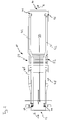
- FIG. 1 shows perspective view of a nozzle 10 for solid fuel injection according to the invention.
- the nozzle 10 comprises an inlet opening 12 and an outlet opening 14.
- the inlet opening 12 is for receiving a stream of coal/air mixture 16 which is symbolically indicated via an arrow.
- the outlet opening 14 is for discharging said stream 16 into a not shown burner.
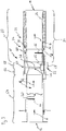
- the inlet opening 12 and the outlet opening 14 are fluidically connected by a flow section 18, as shown in figure 3 .
- a flow cross section 20 of the flow section 18 is varying along a flow direction 22 of the stream of coal/air mixture 16.
- the flow section 18 comprises a flow constriction 24 with a, in the embodiment of the figures, globally minimal flow cross section 26 i.e. the flow cross section 20 has its minimum at the minimal flow cross section 26.
- the flow constriction 24 is fluidically located between the inlet opening 12 and the outlet opening 14, i.e. the stream of coal/air mixture 16 first passes the inlet opening 12 then the flow constriction 24 and then the outlet opening 14.
- the flow cross section 20 of the flow section 18 increases from the flow constriction 24 to the outlet opening 14. In the current embodiment the flow cross section 20 of the flow section 18 continuously increases over the entire extension of the flow section 18 from the flow constriction 24 to the outlet opening 14.
- the flow section 18 comprises a first expansion section 28 and a second expansion section 30 fluidically located between the flow constriction 24 and the outlet opening 14.
- the rate of change of the flow cross section 20 of the first expansion section 28 is higher than the rate of change of the flow cross section 20 of the second expansion section 30.
- the first expansion section 28 is arranged before the second expansion section 30 in flow direction and abuts the later.
- the flow cross section 20 of the first expansion section 28 and the second expansion section 30 increases proportionally to the square of the respective extend in flow direction 22, since the cross sectional area of the flow cross section 20 in each of the expansion section 28, 30 is circular and the diameter of this circular cross-sectional area increases proportional to the extent in flow direction 22.
- the nozzle 10 comprises cooling means 32 which in the current embodiment are implemented as a coolant jacket 34.
- the cooling means 32 i.e. the coolant jacket 34 is arranged in flow direction at least also between the flow constriction 24 and the outlet opening 14. More specifically the coolant jacket extends from before the flow constriction 24 along the extend of the nozzle 10 until close to the outlet opening 14.
- the coolant jacket 34 is constructed to accommodate a liquid coolant 36 indicated symbolically via an arrow.
- the coolant jacket 34 surrounds a wall 38 of the flow section 18.
- the coolant jacket 34 extends in this surrounding fashion in flow direction 22 from before the flow constriction 24 to near the outlet opening 14.
- the coolant jacket 34 is constructed such that a coolant flow direction 40 within the coolant jacket 34 is opposite to the flow direction 22 of the stream of coal/air mixture 16.
- the nozzle 10 comprises several coolant supply lines 42 in the form of pipes.
- the coolant supply lines 42 each have an inlet 44 near the inlet opening 12 of the nozzle 10 and an outlet 46 into the coolant jacket 34, wherein the outlet 46 is located near the outlet opening 14 of the nozzle 10.
- the coolant 36 leaves the coolant jacket 34 coolant exit lines 48.
- the coolant jacket 34 is adapted and arranged to be used with water as the coolant 36. Using other liquids as a coolant 36 is possible and within the scope of this invention.
- the coolant jacket 34 comprises a thermal expansion compensation joint 50 for compensating different thermal expansions of different segments of the nozzle 10 due to unequal temperature distribution along the nozzle 10 during operation.
- the thermal expansion compensation joint 50 in turn comprises a corrugated tube 52.
- the nozzle in the current embodiment comprises a cylindrical segment 54 and in flow direction 22 behind the cylindrical segment 54 a converging conical segment 56 and in flow direction 22 behind the converging conical segment 56 a first diverging conical segment 58 and in flow direction 22 behind the first diverging conical segment 58 a second diverging conical segment 60 wherein the first diverging conical segment 58 has a first angle of divergence 62 that is higher than a second angle of divergence 64 of the second diverging conical segment 60.
- the flow section 18 in the current embodiment is insert-free.
- Insert-free refers to a flow section 18 or a part of it in which there is no inserts in the cross section of the flow section 18 that would cause significant abrupt change in the cross-sectional area of the flow section 18.
- thermo-elements 66 extending into the flow section 18.
- thermo-elements 66 are of such small the dimensions, that they do not cause significant abrupt change in the cross-sectional area of the flow section 18. Therefore they are considered not to constitute inserts within the meaning of the current invention. That static or dynamic mixers arranged in the flow section 18, however, would be considered to constitute inserts within the meaning of the current invention.
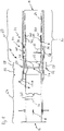
- Figure 4 shows an embodiment that is constructed similar to the embodiment of figures 1 to 3 .
- the nozzle 10 additionally comprises an igniter 68 (shown schematically) which is located in the flow section 18 of the nozzle 10. More specifically in the current embodiment the igniter 68 is located between the flow constriction 24 and the outlet opening 14.
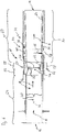
- Figure 5 shows an embodiment that is constructed similar to the embodiment of figures 1 to 3 .
- the wall 38 of the flow section 18 of the nozzle 10 between the flow constriction 24 and the outlet opening 14 is coated with a coating 70 (shown schematically) that comprises a catalyst 72, suitable for catalyzing the reaction of coal with oxygen.
- Figure 6 shows an embodiment that is constructed similar to the embodiment of figures 1 to 3 .
- the nozzle comprises a pivoting mechanism 74 (shown schematically) that allows for pivoting of the outlet opening 14 relative to the inlet opening 12.
- the stream of coal/air mixture 16 is blown into the Inlet opening 12 then propagate along the nozzle 10 passes the flow constriction 24 and subsequently reduces its flow speed.
- Either the stream of coal/air mixture 16 is ignited by the igniter 68 and the flame front is located within the nozzle 10 already due to this ignition and remains there due to the reduced flow speed behind the flow constriction 24 or the stream of coal/air mixture 16 is ignited outside of the nozzle 10, i.e. after it has passed the outlet opening 14.
- the flame front propagates into the nozzle 10 and remains between the flow constriction 24 and the outlet opening 14 during operation of the nozzle 10.
- Auxiliary air can be blown along the outside of the nozzle 10 and can enhance the burning process.
- the coating 70 comprising the catalyst 72, if present, facilitates the location of the flame front within the nozzle 10 since it decreases the amount of energy necessary to start the reaction between coal and oxygen, i.e. the burning of the coal.
Landscapes
- Engineering & Computer Science (AREA)
- Chemical & Material Sciences (AREA)
- Combustion & Propulsion (AREA)
- Mechanical Engineering (AREA)
- General Engineering & Computer Science (AREA)
- Chemical Kinetics & Catalysis (AREA)
- Nozzles (AREA)
Priority Applications (8)
| Application Number | Priority Date | Filing Date | Title |
|---|---|---|---|
| ES17184058T ES2925898T3 (es) | 2017-07-31 | 2017-07-31 | boquilla para carbón con una constricción de flujo |
| PL17184058.0T PL3438531T3 (pl) | 2017-07-31 | 2017-07-31 | Dysza węglowa ze zwężeniem przepływu |
| EP17184058.0A EP3438531B1 (de) | 2017-07-31 | 2017-07-31 | Kohledüse mit strömungsverengung |
| PCT/EP2018/070322 WO2019025288A1 (en) | 2017-07-31 | 2018-07-26 | CHARCOAL NOZZLE WITH FLOW STRAIN |
| CN201880057239.9A CN111433516A (zh) | 2017-07-31 | 2018-07-26 | 具有流动构造体的煤喷嘴 |
| US16/635,698 US11287127B2 (en) | 2017-07-31 | 2018-07-26 | Coal nozzle with a flow constriction |
| KR1020207003925A KR20200037798A (ko) | 2017-07-31 | 2018-07-26 | 유동 협소부를 갖는 석탄 노즐 |
| ZA2020/00611A ZA202000611B (en) | 2017-07-31 | 2020-01-29 | Coal nozzle with a flow constriction |
Applications Claiming Priority (1)
| Application Number | Priority Date | Filing Date | Title |
|---|---|---|---|
| EP17184058.0A EP3438531B1 (de) | 2017-07-31 | 2017-07-31 | Kohledüse mit strömungsverengung |
Publications (2)
| Publication Number | Publication Date |
|---|---|
| EP3438531A1 true EP3438531A1 (de) | 2019-02-06 |
| EP3438531B1 EP3438531B1 (de) | 2022-07-27 |
Family
ID=59501344
Family Applications (1)
| Application Number | Title | Priority Date | Filing Date |
|---|---|---|---|
| EP17184058.0A Active EP3438531B1 (de) | 2017-07-31 | 2017-07-31 | Kohledüse mit strömungsverengung |
Country Status (8)
| Country | Link |
|---|---|
| US (1) | US11287127B2 (de) |
| EP (1) | EP3438531B1 (de) |
| KR (1) | KR20200037798A (de) |
| CN (1) | CN111433516A (de) |
| ES (1) | ES2925898T3 (de) |
| PL (1) | PL3438531T3 (de) |
| WO (1) | WO2019025288A1 (de) |
| ZA (1) | ZA202000611B (de) |
Citations (11)
| Publication number | Priority date | Publication date | Assignee | Title |
|---|---|---|---|---|
| US4500281A (en) * | 1982-08-02 | 1985-02-19 | Phillips Petroleum Company | Burning of fuels |
| JPH01217109A (ja) * | 1988-02-23 | 1989-08-30 | Babcock Hitachi Kk | 微粉炭バーナ |
| US5104310A (en) * | 1986-11-24 | 1992-04-14 | Aga Aktiebolag | Method for reducing the flame temperature of a burner and burner intended therefor |
| EP0687857A2 (de) * | 1994-06-17 | 1995-12-20 | Mitsubishi Jukogyo Kabushiki Kaisha | Kohlenstaubbrenner |
| DE19729607A1 (de) * | 1997-07-10 | 1999-01-14 | Andreas P Rosteuscher | Wärmekraftmaschine |
| US6152051A (en) * | 1996-08-22 | 2000-11-28 | Babcock-Hitachi Kabushiki Kaisha | Powered fuel combustion burner with nozzle flow guide |
| US20040114300A1 (en) * | 2001-02-27 | 2004-06-17 | Aisheng Wang | Assembled cathode and plasma igniter with such cathode |
| US20050255419A1 (en) * | 2004-05-12 | 2005-11-17 | Vladimir Belashchenko | Combustion apparatus for high velocity thermal spraying |
| US20130233212A1 (en) * | 2011-03-31 | 2013-09-12 | Shinya Hamasaki | Burner, reaction furnace such as gasification furnace including the burner, and power plant including the reaction furnace |
| CN103868068A (zh) * | 2014-03-24 | 2014-06-18 | 王龙陵 | 一种高温氧气直接点火和稳燃系统 |
| US8955776B2 (en) | 2010-02-26 | 2015-02-17 | Alstom Technology Ltd | Method of constructing a stationary coal nozzle |
Family Cites Families (8)
| Publication number | Priority date | Publication date | Assignee | Title |
|---|---|---|---|---|
| US3881962A (en) * | 1971-07-29 | 1975-05-06 | Gen Atomic Co | Thermoelectric generator including catalytic burner and cylindrical jacket containing heat exchange fluid |
| US4274587A (en) * | 1979-01-22 | 1981-06-23 | Electric Power Research Institute, Inc. | Water cooled burner nozzle for solvent refined coal |
| JPS61223411A (ja) * | 1985-03-27 | 1986-10-04 | Hitachi Ltd | 微粉炭の触媒燃焼法 |
| CA2167341C (en) * | 1995-01-17 | 2000-03-21 | Joel Vatsky | Tiltable split stream burner assembly with gasket seal |
| GB9709205D0 (en) * | 1997-05-07 | 1997-06-25 | Boc Group Plc | Oxy/oil swirl burner |
| DE102014102139A1 (de) * | 2013-12-13 | 2015-06-18 | Choren Industrietechnik GmbH | Brennstaub-Brenner und Flugstromvergaser für die Herstellung von Synthesegas |
| EP2908051B1 (de) * | 2014-02-12 | 2021-01-13 | General Electric Technology GmbH | Zünderlanze und Verfahren zum Betrieb eines Brenners mit besagter Zünderlanze |
| JP2020030037A (ja) * | 2018-08-20 | 2020-02-27 | 三菱日立パワーシステムズ株式会社 | 固体燃料バーナ |
-
2017
- 2017-07-31 ES ES17184058T patent/ES2925898T3/es active Active
- 2017-07-31 EP EP17184058.0A patent/EP3438531B1/de active Active
- 2017-07-31 PL PL17184058.0T patent/PL3438531T3/pl unknown
-
2018
- 2018-07-26 US US16/635,698 patent/US11287127B2/en active Active
- 2018-07-26 CN CN201880057239.9A patent/CN111433516A/zh active Pending
- 2018-07-26 WO PCT/EP2018/070322 patent/WO2019025288A1/en not_active Ceased
- 2018-07-26 KR KR1020207003925A patent/KR20200037798A/ko not_active Abandoned
-
2020
- 2020-01-29 ZA ZA2020/00611A patent/ZA202000611B/en unknown
Patent Citations (11)
| Publication number | Priority date | Publication date | Assignee | Title |
|---|---|---|---|---|
| US4500281A (en) * | 1982-08-02 | 1985-02-19 | Phillips Petroleum Company | Burning of fuels |
| US5104310A (en) * | 1986-11-24 | 1992-04-14 | Aga Aktiebolag | Method for reducing the flame temperature of a burner and burner intended therefor |
| JPH01217109A (ja) * | 1988-02-23 | 1989-08-30 | Babcock Hitachi Kk | 微粉炭バーナ |
| EP0687857A2 (de) * | 1994-06-17 | 1995-12-20 | Mitsubishi Jukogyo Kabushiki Kaisha | Kohlenstaubbrenner |
| US6152051A (en) * | 1996-08-22 | 2000-11-28 | Babcock-Hitachi Kabushiki Kaisha | Powered fuel combustion burner with nozzle flow guide |
| DE19729607A1 (de) * | 1997-07-10 | 1999-01-14 | Andreas P Rosteuscher | Wärmekraftmaschine |
| US20040114300A1 (en) * | 2001-02-27 | 2004-06-17 | Aisheng Wang | Assembled cathode and plasma igniter with such cathode |
| US20050255419A1 (en) * | 2004-05-12 | 2005-11-17 | Vladimir Belashchenko | Combustion apparatus for high velocity thermal spraying |
| US8955776B2 (en) | 2010-02-26 | 2015-02-17 | Alstom Technology Ltd | Method of constructing a stationary coal nozzle |
| US20130233212A1 (en) * | 2011-03-31 | 2013-09-12 | Shinya Hamasaki | Burner, reaction furnace such as gasification furnace including the burner, and power plant including the reaction furnace |
| CN103868068A (zh) * | 2014-03-24 | 2014-06-18 | 王龙陵 | 一种高温氧气直接点火和稳燃系统 |
Also Published As
| Publication number | Publication date |
|---|---|
| US20200309363A1 (en) | 2020-10-01 |
| CN111433516A (zh) | 2020-07-17 |
| US11287127B2 (en) | 2022-03-29 |
| ZA202000611B (en) | 2021-08-25 |
| PL3438531T3 (pl) | 2022-09-12 |
| EP3438531B1 (de) | 2022-07-27 |
| ES2925898T3 (es) | 2022-10-20 |
| WO2019025288A1 (en) | 2019-02-07 |
| KR20200037798A (ko) | 2020-04-09 |
Similar Documents
| Publication | Publication Date | Title |
|---|---|---|
| JP4261401B2 (ja) | バーナと燃料燃焼方法及びボイラの改造方法 | |
| RU2589587C1 (ru) | Горелка для газообразного топлива с высоким энергосбережением и эффективностью сгорания, с низкой эмиссией загрязняющих веществ и высокой теплопередачей | |
| JP5409779B2 (ja) | 低窒素酸化物炉用燃料噴射器 | |
| RU2627759C2 (ru) | Последовательное сгорание со смесителем разбавляющего газа | |
| KR900006242B1 (ko) | 미분탄버어너의 1차공기 교환장치와 그 교환방법 | |
| US10458646B2 (en) | Low NOx, high efficiency, high temperature, staged recirculating burner and radiant tube combustion system | |
| NL2029663B1 (en) | Iron fuel combustion arrangement | |
| EP3152490B1 (de) | Nicht symmetrischer brenner mit niedrigem nox-gehalt und verfahren | |
| JPS60181505A (ja) | 石炭燃焼炉用の燃焼装置と方法 | |
| US5724897A (en) | Split flame burner for reducing NOx formation | |
| JPS6323442B2 (de) | ||
| CN102459102B (zh) | 通过小炉的氧气燃料燃烧器 | |
| SE531133C2 (sv) | Katalytisk brännare och reglerförfarande | |
| CN101932876B (zh) | 燃烧加热器 | |
| US20100081102A1 (en) | Systems and methods for facilitating varying size coal pipes for a pulverized coal burner | |
| JP2016109349A (ja) | 固体燃料バーナ及び固体燃料バーナを備えたボイラ | |
| CN101349435B (zh) | 一种等离子体点火燃烧器 | |
| US11287127B2 (en) | Coal nozzle with a flow constriction | |
| JP2008107031A (ja) | 管状火炎バーナおよびラジアントチューブ式加熱装置 | |
| JP4910633B2 (ja) | 長火炎バーナおよびラジアントチューブ式加熱装置 | |
| GB1585410A (en) | Burner | |
| RU2309332C1 (ru) | Многофункциональная горелка | |
| JP7262521B2 (ja) | ガスバーナ、及び燃焼設備 | |
| RU2143639C1 (ru) | Топочное устройство | |
| CN102454985B (zh) | 一种煤粉燃烧器及煤粉锅炉 |
Legal Events
| Date | Code | Title | Description |
|---|---|---|---|
| PUAI | Public reference made under article 153(3) epc to a published international application that has entered the european phase |
Free format text: ORIGINAL CODE: 0009012 |
|
| STAA | Information on the status of an ep patent application or granted ep patent |
Free format text: STATUS: THE APPLICATION HAS BEEN PUBLISHED |
|
| AK | Designated contracting states |
Kind code of ref document: A1 Designated state(s): AL AT BE BG CH CY CZ DE DK EE ES FI FR GB GR HR HU IE IS IT LI LT LU LV MC MK MT NL NO PL PT RO RS SE SI SK SM TR |
|
| AX | Request for extension of the european patent |
Extension state: BA ME |
|
| STAA | Information on the status of an ep patent application or granted ep patent |
Free format text: STATUS: REQUEST FOR EXAMINATION WAS MADE |
|
| 17P | Request for examination filed |
Effective date: 20190806 |
|
| RBV | Designated contracting states (corrected) |
Designated state(s): AL AT BE BG CH CY CZ DE DK EE ES FI FR GB GR HR HU IE IS IT LI LT LU LV MC MK MT NL NO PL PT RO RS SE SI SK SM TR |
|
| STAA | Information on the status of an ep patent application or granted ep patent |
Free format text: STATUS: EXAMINATION IS IN PROGRESS |
|
| 17Q | First examination report despatched |
Effective date: 20200115 |
|
| RAP3 | Party data changed (applicant data changed or rights of an application transferred) |
Owner name: GENERAL ELECTRIC TECHNOLOGY GMBH |
|
| GRAP | Despatch of communication of intention to grant a patent |
Free format text: ORIGINAL CODE: EPIDOSNIGR1 |
|
| STAA | Information on the status of an ep patent application or granted ep patent |
Free format text: STATUS: GRANT OF PATENT IS INTENDED |
|
| INTG | Intention to grant announced |
Effective date: 20220225 |
|
| GRAS | Grant fee paid |
Free format text: ORIGINAL CODE: EPIDOSNIGR3 |
|
| GRAA | (expected) grant |
Free format text: ORIGINAL CODE: 0009210 |
|
| STAA | Information on the status of an ep patent application or granted ep patent |
Free format text: STATUS: THE PATENT HAS BEEN GRANTED |
|
| AK | Designated contracting states |
Kind code of ref document: B1 Designated state(s): AL AT BE BG CH CY CZ DE DK EE ES FI FR GB GR HR HU IE IS IT LI LT LU LV MC MK MT NL NO PL PT RO RS SE SI SK SM TR |
|
| REG | Reference to a national code |
Ref country code: CH Ref legal event code: EP |
|
| REG | Reference to a national code |
Ref country code: AT Ref legal event code: REF Ref document number: 1507283 Country of ref document: AT Kind code of ref document: T Effective date: 20220815 |
|
| REG | Reference to a national code |
Ref country code: DE Ref legal event code: R096 Ref document number: 602017059821 Country of ref document: DE |
|
| REG | Reference to a national code |
Ref country code: IE Ref legal event code: FG4D |
|
| REG | Reference to a national code |
Ref country code: ES Ref legal event code: FG2A Ref document number: 2925898 Country of ref document: ES Kind code of ref document: T3 Effective date: 20221020 |
|
| REG | Reference to a national code |
Ref country code: GR Ref legal event code: EP Ref document number: 20220401789 Country of ref document: GR Effective date: 20221010 |
|
| REG | Reference to a national code |
Ref country code: LT Ref legal event code: MG9D |
|
| REG | Reference to a national code |
Ref country code: NL Ref legal event code: MP Effective date: 20220727 |
|
| PG25 | Lapsed in a contracting state [announced via postgrant information from national office to epo] |
Ref country code: SE Free format text: LAPSE BECAUSE OF FAILURE TO SUBMIT A TRANSLATION OF THE DESCRIPTION OR TO PAY THE FEE WITHIN THE PRESCRIBED TIME-LIMIT Effective date: 20220727 Ref country code: RS Free format text: LAPSE BECAUSE OF FAILURE TO SUBMIT A TRANSLATION OF THE DESCRIPTION OR TO PAY THE FEE WITHIN THE PRESCRIBED TIME-LIMIT Effective date: 20220727 Ref country code: PT Free format text: LAPSE BECAUSE OF FAILURE TO SUBMIT A TRANSLATION OF THE DESCRIPTION OR TO PAY THE FEE WITHIN THE PRESCRIBED TIME-LIMIT Effective date: 20221128 Ref country code: NO Free format text: LAPSE BECAUSE OF FAILURE TO SUBMIT A TRANSLATION OF THE DESCRIPTION OR TO PAY THE FEE WITHIN THE PRESCRIBED TIME-LIMIT Effective date: 20221027 Ref country code: NL Free format text: LAPSE BECAUSE OF FAILURE TO SUBMIT A TRANSLATION OF THE DESCRIPTION OR TO PAY THE FEE WITHIN THE PRESCRIBED TIME-LIMIT Effective date: 20220727 Ref country code: LV Free format text: LAPSE BECAUSE OF FAILURE TO SUBMIT A TRANSLATION OF THE DESCRIPTION OR TO PAY THE FEE WITHIN THE PRESCRIBED TIME-LIMIT Effective date: 20220727 Ref country code: LT Free format text: LAPSE BECAUSE OF FAILURE TO SUBMIT A TRANSLATION OF THE DESCRIPTION OR TO PAY THE FEE WITHIN THE PRESCRIBED TIME-LIMIT Effective date: 20220727 Ref country code: FI Free format text: LAPSE BECAUSE OF FAILURE TO SUBMIT A TRANSLATION OF THE DESCRIPTION OR TO PAY THE FEE WITHIN THE PRESCRIBED TIME-LIMIT Effective date: 20220727 |
|
| REG | Reference to a national code |
Ref country code: AT Ref legal event code: MK05 Ref document number: 1507283 Country of ref document: AT Kind code of ref document: T Effective date: 20220727 |
|
| PG25 | Lapsed in a contracting state [announced via postgrant information from national office to epo] |
Ref country code: IS Free format text: LAPSE BECAUSE OF FAILURE TO SUBMIT A TRANSLATION OF THE DESCRIPTION OR TO PAY THE FEE WITHIN THE PRESCRIBED TIME-LIMIT Effective date: 20221127 Ref country code: HR Free format text: LAPSE BECAUSE OF FAILURE TO SUBMIT A TRANSLATION OF THE DESCRIPTION OR TO PAY THE FEE WITHIN THE PRESCRIBED TIME-LIMIT Effective date: 20220727 |
|
| REG | Reference to a national code |
Ref country code: CH Ref legal event code: PL |
|
| REG | Reference to a national code |
Ref country code: BE Ref legal event code: MM Effective date: 20220731 |
|
| PG25 | Lapsed in a contracting state [announced via postgrant information from national office to epo] |
Ref country code: SM Free format text: LAPSE BECAUSE OF FAILURE TO SUBMIT A TRANSLATION OF THE DESCRIPTION OR TO PAY THE FEE WITHIN THE PRESCRIBED TIME-LIMIT Effective date: 20220727 Ref country code: RO Free format text: LAPSE BECAUSE OF FAILURE TO SUBMIT A TRANSLATION OF THE DESCRIPTION OR TO PAY THE FEE WITHIN THE PRESCRIBED TIME-LIMIT Effective date: 20220727 Ref country code: MC Free format text: LAPSE BECAUSE OF FAILURE TO SUBMIT A TRANSLATION OF THE DESCRIPTION OR TO PAY THE FEE WITHIN THE PRESCRIBED TIME-LIMIT Effective date: 20220727 Ref country code: LU Free format text: LAPSE BECAUSE OF NON-PAYMENT OF DUE FEES Effective date: 20220731 Ref country code: LI Free format text: LAPSE BECAUSE OF NON-PAYMENT OF DUE FEES Effective date: 20220731 Ref country code: DK Free format text: LAPSE BECAUSE OF FAILURE TO SUBMIT A TRANSLATION OF THE DESCRIPTION OR TO PAY THE FEE WITHIN THE PRESCRIBED TIME-LIMIT Effective date: 20220727 Ref country code: CH Free format text: LAPSE BECAUSE OF NON-PAYMENT OF DUE FEES Effective date: 20220731 Ref country code: AT Free format text: LAPSE BECAUSE OF FAILURE TO SUBMIT A TRANSLATION OF THE DESCRIPTION OR TO PAY THE FEE WITHIN THE PRESCRIBED TIME-LIMIT Effective date: 20220727 |
|
| REG | Reference to a national code |
Ref country code: DE Ref legal event code: R097 Ref document number: 602017059821 Country of ref document: DE |
|
| PG25 | Lapsed in a contracting state [announced via postgrant information from national office to epo] |
Ref country code: SK Free format text: LAPSE BECAUSE OF FAILURE TO SUBMIT A TRANSLATION OF THE DESCRIPTION OR TO PAY THE FEE WITHIN THE PRESCRIBED TIME-LIMIT Effective date: 20220727 Ref country code: EE Free format text: LAPSE BECAUSE OF FAILURE TO SUBMIT A TRANSLATION OF THE DESCRIPTION OR TO PAY THE FEE WITHIN THE PRESCRIBED TIME-LIMIT Effective date: 20220727 Ref country code: BE Free format text: LAPSE BECAUSE OF NON-PAYMENT OF DUE FEES Effective date: 20220731 |
|
| PLBE | No opposition filed within time limit |
Free format text: ORIGINAL CODE: 0009261 |
|
| STAA | Information on the status of an ep patent application or granted ep patent |
Free format text: STATUS: NO OPPOSITION FILED WITHIN TIME LIMIT |
|
| P01 | Opt-out of the competence of the unified patent court (upc) registered |
Effective date: 20230523 |
|
| PG25 | Lapsed in a contracting state [announced via postgrant information from national office to epo] |
Ref country code: AL Free format text: LAPSE BECAUSE OF FAILURE TO SUBMIT A TRANSLATION OF THE DESCRIPTION OR TO PAY THE FEE WITHIN THE PRESCRIBED TIME-LIMIT Effective date: 20220727 |
|
| 26N | No opposition filed |
Effective date: 20230502 |
|
| PG25 | Lapsed in a contracting state [announced via postgrant information from national office to epo] |
Ref country code: IE Free format text: LAPSE BECAUSE OF NON-PAYMENT OF DUE FEES Effective date: 20220731 Ref country code: FR Free format text: LAPSE BECAUSE OF NON-PAYMENT OF DUE FEES Effective date: 20220927 |
|
| PGFP | Annual fee paid to national office [announced via postgrant information from national office to epo] |
Ref country code: IT Payment date: 20230620 Year of fee payment: 7 Ref country code: CZ Payment date: 20230623 Year of fee payment: 7 |
|
| PG25 | Lapsed in a contracting state [announced via postgrant information from national office to epo] |
Ref country code: SI Free format text: LAPSE BECAUSE OF FAILURE TO SUBMIT A TRANSLATION OF THE DESCRIPTION OR TO PAY THE FEE WITHIN THE PRESCRIBED TIME-LIMIT Effective date: 20220727 |
|
| PGFP | Annual fee paid to national office [announced via postgrant information from national office to epo] |
Ref country code: PL Payment date: 20230621 Year of fee payment: 7 Ref country code: GR Payment date: 20230622 Year of fee payment: 7 |
|
| PGFP | Annual fee paid to national office [announced via postgrant information from national office to epo] |
Ref country code: GB Payment date: 20230620 Year of fee payment: 7 Ref country code: ES Payment date: 20230801 Year of fee payment: 7 |
|
| PGFP | Annual fee paid to national office [announced via postgrant information from national office to epo] |
Ref country code: DE Payment date: 20230620 Year of fee payment: 7 |
|
| PG25 | Lapsed in a contracting state [announced via postgrant information from national office to epo] |
Ref country code: HU Free format text: LAPSE BECAUSE OF FAILURE TO SUBMIT A TRANSLATION OF THE DESCRIPTION OR TO PAY THE FEE WITHIN THE PRESCRIBED TIME-LIMIT; INVALID AB INITIO Effective date: 20170731 |
|
| PG25 | Lapsed in a contracting state [announced via postgrant information from national office to epo] |
Ref country code: MK Free format text: LAPSE BECAUSE OF FAILURE TO SUBMIT A TRANSLATION OF THE DESCRIPTION OR TO PAY THE FEE WITHIN THE PRESCRIBED TIME-LIMIT Effective date: 20220727 Ref country code: CY Free format text: LAPSE BECAUSE OF FAILURE TO SUBMIT A TRANSLATION OF THE DESCRIPTION OR TO PAY THE FEE WITHIN THE PRESCRIBED TIME-LIMIT Effective date: 20220727 |
|
| PG25 | Lapsed in a contracting state [announced via postgrant information from national office to epo] |
Ref country code: BG Free format text: LAPSE BECAUSE OF FAILURE TO SUBMIT A TRANSLATION OF THE DESCRIPTION OR TO PAY THE FEE WITHIN THE PRESCRIBED TIME-LIMIT Effective date: 20220727 |
|
| PG25 | Lapsed in a contracting state [announced via postgrant information from national office to epo] |
Ref country code: MT Free format text: LAPSE BECAUSE OF FAILURE TO SUBMIT A TRANSLATION OF THE DESCRIPTION OR TO PAY THE FEE WITHIN THE PRESCRIBED TIME-LIMIT Effective date: 20220727 |
|
| REG | Reference to a national code |
Ref country code: DE Ref legal event code: R119 Ref document number: 602017059821 Country of ref document: DE |
|
| GBPC | Gb: european patent ceased through non-payment of renewal fee |
Effective date: 20240731 |
|
| PG25 | Lapsed in a contracting state [announced via postgrant information from national office to epo] |
Ref country code: DE Free format text: LAPSE BECAUSE OF NON-PAYMENT OF DUE FEES Effective date: 20250201 |
|
| PG25 | Lapsed in a contracting state [announced via postgrant information from national office to epo] |
Ref country code: GR Free format text: LAPSE BECAUSE OF NON-PAYMENT OF DUE FEES Effective date: 20250205 |
|
| PG25 | Lapsed in a contracting state [announced via postgrant information from national office to epo] |
Ref country code: CZ Free format text: LAPSE BECAUSE OF NON-PAYMENT OF DUE FEES Effective date: 20240731 |
|
| PG25 | Lapsed in a contracting state [announced via postgrant information from national office to epo] |
Ref country code: GB Free format text: LAPSE BECAUSE OF NON-PAYMENT OF DUE FEES Effective date: 20240731 |
|
| PG25 | Lapsed in a contracting state [announced via postgrant information from national office to epo] |
Ref country code: IT Free format text: LAPSE BECAUSE OF NON-PAYMENT OF DUE FEES Effective date: 20240731 |
|
| PGFP | Annual fee paid to national office [announced via postgrant information from national office to epo] |
Ref country code: TR Payment date: 20250630 Year of fee payment: 9 |
|
| REG | Reference to a national code |
Ref country code: ES Ref legal event code: FD2A Effective date: 20250903 |
|
| PG25 | Lapsed in a contracting state [announced via postgrant information from national office to epo] |
Ref country code: ES Free format text: LAPSE BECAUSE OF NON-PAYMENT OF DUE FEES Effective date: 20240801 |
|
| PG25 | Lapsed in a contracting state [announced via postgrant information from national office to epo] |
Ref country code: PL Free format text: LAPSE BECAUSE OF NON-PAYMENT OF DUE FEES Effective date: 20240731 |