EP3438558A1 - Procédé de fonctionnement d'un dispositif mélangeur et ledit dispositif mélangeur - Google Patents
Procédé de fonctionnement d'un dispositif mélangeur et ledit dispositif mélangeur Download PDFInfo
- Publication number
- EP3438558A1 EP3438558A1 EP17184778.3A EP17184778A EP3438558A1 EP 3438558 A1 EP3438558 A1 EP 3438558A1 EP 17184778 A EP17184778 A EP 17184778A EP 3438558 A1 EP3438558 A1 EP 3438558A1
- Authority
- EP
- European Patent Office
- Prior art keywords
- pump unit
- circulating pump
- heating medium
- temperature
- mixing device
- Prior art date
- Legal status (The legal status is an assumption and is not a legal conclusion. Google has not performed a legal analysis and makes no representation as to the accuracy of the status listed.)
- Withdrawn
Links
Images





Classifications
-
- F—MECHANICAL ENGINEERING; LIGHTING; HEATING; WEAPONS; BLASTING
- F24—HEATING; RANGES; VENTILATING
- F24D—DOMESTIC- OR SPACE-HEATING SYSTEMS, e.g. CENTRAL HEATING SYSTEMS; DOMESTIC HOT-WATER SUPPLY SYSTEMS; ELEMENTS OR COMPONENTS THEREFOR
- F24D19/00—Details
- F24D19/10—Arrangement or mounting of control or safety devices
- F24D19/1006—Arrangement or mounting of control or safety devices for water heating systems
- F24D19/1009—Arrangement or mounting of control or safety devices for water heating systems for central heating
- F24D19/1012—Arrangement or mounting of control or safety devices for water heating systems for central heating by regulating the speed of a pump
-
- F—MECHANICAL ENGINEERING; LIGHTING; HEATING; WEAPONS; BLASTING
- F24—HEATING; RANGES; VENTILATING
- F24D—DOMESTIC- OR SPACE-HEATING SYSTEMS, e.g. CENTRAL HEATING SYSTEMS; DOMESTIC HOT-WATER SUPPLY SYSTEMS; ELEMENTS OR COMPONENTS THEREFOR
- F24D3/00—Hot-water central heating systems
- F24D3/10—Feed-line arrangements, e.g. providing for heat-accumulator tanks, expansion tanks ; Hydraulic components of a central heating system
- F24D3/1058—Feed-line arrangements, e.g. providing for heat-accumulator tanks, expansion tanks ; Hydraulic components of a central heating system disposition of pipes and pipe connections
- F24D3/1066—Distributors for heating liquids
-
- F—MECHANICAL ENGINEERING; LIGHTING; HEATING; WEAPONS; BLASTING
- F24—HEATING; RANGES; VENTILATING
- F24H—FLUID HEATERS, e.g. WATER OR AIR HEATERS, HAVING HEAT-GENERATING MEANS, e.g. HEAT PUMPS, IN GENERAL
- F24H15/00—Control of fluid heaters
- F24H15/20—Control of fluid heaters characterised by control inputs
-
- F—MECHANICAL ENGINEERING; LIGHTING; HEATING; WEAPONS; BLASTING
- F24—HEATING; RANGES; VENTILATING
- F24H—FLUID HEATERS, e.g. WATER OR AIR HEATERS, HAVING HEAT-GENERATING MEANS, e.g. HEAT PUMPS, IN GENERAL
- F24H15/00—Control of fluid heaters
- F24H15/30—Control of fluid heaters characterised by control outputs; characterised by the components to be controlled
- F24H15/335—Control of pumps, e.g. on-off control
- F24H15/34—Control of the speed of pumps
-
- F—MECHANICAL ENGINEERING; LIGHTING; HEATING; WEAPONS; BLASTING
- F24—HEATING; RANGES; VENTILATING
- F24D—DOMESTIC- OR SPACE-HEATING SYSTEMS, e.g. CENTRAL HEATING SYSTEMS; DOMESTIC HOT-WATER SUPPLY SYSTEMS; ELEMENTS OR COMPONENTS THEREFOR
- F24D2220/00—Components of central heating installations excluding heat sources
- F24D2220/02—Fluid distribution means
- F24D2220/0207—Pumps
-
- F—MECHANICAL ENGINEERING; LIGHTING; HEATING; WEAPONS; BLASTING
- F24—HEATING; RANGES; VENTILATING
- F24D—DOMESTIC- OR SPACE-HEATING SYSTEMS, e.g. CENTRAL HEATING SYSTEMS; DOMESTIC HOT-WATER SUPPLY SYSTEMS; ELEMENTS OR COMPONENTS THEREFOR
- F24D2220/00—Components of central heating installations excluding heat sources
- F24D2220/02—Fluid distribution means
- F24D2220/0228—Branched distribution conduits
-
- F—MECHANICAL ENGINEERING; LIGHTING; HEATING; WEAPONS; BLASTING
- F24—HEATING; RANGES; VENTILATING
- F24D—DOMESTIC- OR SPACE-HEATING SYSTEMS, e.g. CENTRAL HEATING SYSTEMS; DOMESTIC HOT-WATER SUPPLY SYSTEMS; ELEMENTS OR COMPONENTS THEREFOR
- F24D2220/00—Components of central heating installations excluding heat sources
- F24D2220/04—Sensors
- F24D2220/042—Temperature sensors
-
- Y—GENERAL TAGGING OF NEW TECHNOLOGICAL DEVELOPMENTS; GENERAL TAGGING OF CROSS-SECTIONAL TECHNOLOGIES SPANNING OVER SEVERAL SECTIONS OF THE IPC; TECHNICAL SUBJECTS COVERED BY FORMER USPC CROSS-REFERENCE ART COLLECTIONS [XRACs] AND DIGESTS
- Y02—TECHNOLOGIES OR APPLICATIONS FOR MITIGATION OR ADAPTATION AGAINST CLIMATE CHANGE
- Y02B—CLIMATE CHANGE MITIGATION TECHNOLOGIES RELATED TO BUILDINGS, e.g. HOUSING, HOUSE APPLIANCES OR RELATED END-USER APPLICATIONS
- Y02B30/00—Energy efficient heating, ventilation or air conditioning [HVAC]
- Y02B30/70—Efficient control or regulation technologies, e.g. for control of refrigerant flow, motor or heating
Definitions
- the invention relates to a method for operating a mixing device in a heating system and a mixing device.
- mixers or mixing devices are used to adjust the temperature of a heating medium and in particular to be able to reduce. This is particularly necessary for underfloor heating, which operates at a lower flow temperature than that provided by a boiler.
- heated heating medium in particular water, mixed with cold heating medium from the return to the temperature.
- mixing valves are usually used, which are thermostatically or by electric motor driven to change the mixing ratio for adjusting the temperature.
- a heating system basically a system for controlling the temperature of a room or a facility is understood, regardless of whether it is used for heating or cooling.
- a heating system in the context of this invention is also an air conditioner to understand, even if only the term "heating system" is used below.
- the method is used in a mixing device in which two Schumediumströme different temperatures are mixed for adjusting the temperature of the heating medium. Such mixtures take place, for example, in underfloor heating systems in which cold heating medium from a reflux is admixed with a high-temperature feed in order to reduce the heating medium temperature. Conversely, a required amount of heated heating medium can be admixed with a circulating-promoted heating medium in order to increase the temperature of the circulating-promoted heating medium.
- the mixing device in which the method is used moreover, has a circulating pump unit conveying the heating medium. According to the invention, this circulating pump unit is regulated in its rotational speed as a function of a temperature value detected in the heating medium. D.
- the circulating pump unit has a speed control and in particular a speed controller, via which the speed is variable. This can be done for example via a controlled by a frequency converter electric drive motor.
- the circulating pump units are regulated as a function of the flow and / or the pressure, ie the rotational speed is adjusted so that a desired flow and / or a desired pressure on the output side of the circulating pump unit is achieved.
- a desired temperature value is now to be achieved, and the circulating pump unit is regulated in its rotational speed in accordance with the temperature.
- the rotational speed of the at least one circulating pump assembly is controlled such that the detected temperature value corresponds to or is approximated to a predetermined temperature setpoint, the temperature setpoint preferably being predefined as a function of a room temperature and / or an outside temperature.
- the temperature setpoint can be determined for example via a heating curve, which sets the temperature setpoint outside and / or room temperature dependent, as is common in modern heating systems.
- the desired temperature setpoint in the mixing device is achieved by appropriate speed adjustment of the circulating pump unit. That is, the speed of the circulating pump unit is changed so that the detected temperature value is approached or ideally reached the temperature setpoint.
- the two heating medium streams are preferably mixed at an orifice point and the temperature value is detected downstream of the mixing point in the heating medium.
- the heating medium temperature can be controlled or adjusted downstream of the mixing point by speed control or speed adjustment of Ummélzpumpenaggregates.
- the at least one circulating pump unit causes at least one of the two heating medium flows. That is, the circulating pump unit is arranged to convey or circulate the heating medium. Preferably, the circulating pump unit is arranged downstream of a mixing point, so that it promotes the mixed heating medium. This means that the mixture of the two heating medium flows takes place on the suction side of the circulating pump unit.
- the at least one circulation pump unit which is regulated in its rotational speed as a function of a temperature value detected in the heating medium, forms a first circulating pump unit and there is a second circulating pump unit which effects one of the heating medium flows.
- the first circulating pump unit can be arranged in one of the two heating medium flows or, as described above, downstream of the mixing point, so that it promotes the mixed Schumediumströme. If the first circulating pump unit, which is temperature-dependent controlled in its speed, downstream of the mixing point, preferably the second circulating pump unit is arranged so that it causes only one of the two Schumediumströme.
- the second circulating pump unit can be regulated, for example, as a function of pressure or flow.
- the temperature-controlled circulating pump unit is arranged only in one of the two heating medium flows and then preferably a second circulating pump unit downstream of the mixing point is arranged, which is conventionally controlled pressure or flow dependent.
- the at least one circulating pump unit causes at least one of the two heating medium flows, wherein the at least one circulating pump unit preferably the heating medium promotes downstream of a mixing point of the two Schumediumströme.
- the circulating pump unit acts on both heating medium flows.
- the at least one circulation pump unit which is regulated in its rotational speed as a function of a temperature value detected in the heating medium, forms a first circulating pump unit and there is a second circulating pump unit, which preferably acts in one of the heating medium flows.
- the temperature-controlled circulating pump unit can be arranged in the manner described above downstream of a mixing point and thus act on both Thompsonmediumströme, while a second Um Georgzpumpenaggregat acts in one of the Schumediumströme and there provides a form upstream of the mixing point. So z. B. heated heating medium in the manner of an injection circuit are fed to the mixing point.
- the second circulating pump unit may preferably be regulated in its rotational speed as a function of a pressure and / or a flow of the heating medium or else in dependence on a temperature value detected in the heating medium.
- This temperature-controlled circulating pump unit may for example be a circulating pump unit, which is arranged downstream of the mixing point. However, it may also be a circulating pump unit, which acts only in one of the Schumediumströme.
- a circulatory pump unit which is arranged downstream of the mixing point, could then, for example, in a conventional manner, also only compressively and / or flow-dependent are controlled in its speed.
- at least one of the existing Umisselzpumpenaggregate which acts hydraulically on one or both Schumediumströme the mixing device is temperature-dependent, so as to vary by changing the speed of Umisselzpumpenaggregates the mixing ratio between the Schumediumströmen and so a desired set temperature in the heating medium to achieve by controlling the circulating pump unit.
- a presetting in particular a manual presetting of the system or the mixing device with the following steps before the start of operation of the above-described temperature-dependent speed control of the circulating pump unit.
- the circulating pump unit is set to a required differential pressure. This ensures that the circulating pump unit generates the required differential pressure for the respective heating circuit.
- D. h. In this first step is a hydraulic adjustment of the setting of the circulating pump unit to the system.
- the two heating medium flows are adjusted manually so that a desired temperature of the heating medium is achieved.
- the desired temperature of the heating medium a flow temperature value can be used, which would result in given ambient conditions, such as a given outside temperature, after a heating curve.
- This manual presetting of the heating medium flows preferably takes place via flow control valves, which are provided in the pipelines for the heating medium flows and in particular can be integrated into the mixing device.
- the valves are preferably manually adjustable. These default settings cause different hydraulic resistances, which act on the two Schumediumströme, balanced and made a basic hydraulic adjustment. After this default, the temperature control is then taken by speed adjustment of the circulating pump unit in operation. Due to the pre-setting made, then, slight changes in the rotational speed of the circulating pump unit are sufficient in order to be able to carry out a temperature adaptation or regulation, for example by changing a mixing ratio in the mixing device.
- the subject of the invention is also a mixing device which is designed for use in a heating system for mixing two heating medium streams.
- the mixing device is designed in particular for carrying out the method described above.
- the mixing device has at least one circulating pump unit conveying the heating medium, which is adjustable, in particular controllable, in its rotational speed.
- the circulation pump unit preferably has an electric drive motor with a speed controller, preferably using a frequency converter.
- the electric drive motor of the circulating pump unit is preferably designed as a wet-running electric drive motor, ie with a split tube or split pot between the rotor and stator.
- the electric drive motor drives at least one impeller of Umisselzpumpenaggregates rotating, which is located in a flow path for the heating medium.
- the mixing device furthermore has a temperature sensor which is arranged such that it detects a temperature value of the heating medium.
- the temperature sensor is preferably located at or in a flow path downstream of a mixing point at which the two heating medium streams are mixed.
- the circulating pump unit according to the invention is equipped with a control device which is designed so that it controls the speed of the circulating pump unit, d. H. the at least one impeller of the circulating pump unit adjusts in dependence on a temperature value detected by the temperature sensor.
- the control device is designed such that it carries out a temperature-dependent speed setting or speed control of the circulating pump unit. In this way, a desired temperature value for the heating medium can be adjusted by changing the speed.
- the mixing device has a mixing or orifice point at which the two heating medium streams are mixed.
- the at least one circulating pump unit is preferably arranged in a flow path downstream of this mixing point.
- the circulating pump unit acts on both heating medium flows, since these are mixed on the suction side of the circulating pump unit.
- the at least one circulating pump unit which is controlled by the control device in its rotational speed as a function of a detected temperature in the heating medium, is preferably a first circulating pump unit and it is also in the mixing device, a second Um Georgzpumpenaggregat available, which is more preferably located in one of the Schumediumströme.
- the temperature-controlled circulating pump unit is preferably arranged downstream of a mixing point, while the second circulating pump unit acts only in one of the heating medium flows, so that this heating medium flow to the mixing point with a form is supplied.
- This second circulating pump unit may further preferably be arranged in a heating boiler or a heat source and / or additionally serve to supply a further heating circuit.
- the pre-pressure can contribute to causing a change in the mixing ratio via the temperature-dependent speed control of the first circulating pump unit by changing the hydraulic resistances in the mixing device.
- the second circulating pump unit further preferably has a control unit independent of the first circulating pump unit, which is preferably designed such that it adjusts the speed of the second circulating pump unit as a function of a pressure and / or flow of the heating medium.
- the control device is designed such that it adjusts the rotational speed of the second circulating pump unit as a function of a temperature of the heating medium.
- the independent control device for the second circulation pump unit has the advantage that the mixing device with the control device for temperature-dependent speed control of the first circulation pump unit can be realized independently and easily in an existing heating system, which already has a circulating pump unit, can be integrated.
- the circulating pump unit which is present anyway in the heating system, then forms the described second circulating pump unit.
- the first and the second circulating pump unit may have a common control device and / or two control devices which communicate with one another such that the first and second circulating pump units are regulated in their rotational speeds as a function of the temperature value detected by the at least one temperature sensor , If two mutually communicating control devices are provided, they have suitable communication interfaces for data exchange.
- the communication interfaces may be wired or wireless, such as wireless LAN, Bluetooth or other suitable wireless interfaces.
- the first or the second circulating pump unit are arranged such that it additionally supplies a further heating circuit with heating medium.
- the second circulation pump unit as described above by way of example, is a circulating pump unit which is assigned, for example, to a heating boiler or a heating system, then this circulation pump unit can supply heating circuits which are operated at a higher flow temperature, while the described first circulating pump unit of the mixing device then preferably one or more Heating circuits with lower flow temperature, in particular heating circuits of a floor heating, supplied with heating medium.
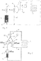
- Fig. 1 schematically shows a conventional heating circuit for a floor heating 2, ie a heating circuit according to the prior art.
- the heat source is a boiler 4, for example, a gas boiler with an integrated circulation pump 6.
- a further circulating pump unit 8 with an impeller 10 and an electric drive motor 12 is provided for the underfloor heating circuit 2.
- a mixing device is provided here, which has a mixing point 14 which is located on the suction side of the impeller 10.
- a feed line 18, via which the water or heating medium heated by the heating boiler 4 flows and at the mixing point 14 by the circulating pump unit 6, opens Pressure is injected.
- two flow regulating valves R hot and R cold are provided in this embodiment.
- the regulating valve R hot is arranged in the supply line 18 and the regulating valve R cold in the return line 16.
- the valves can for example be controlled by a control device via an electric drive.
- the regulating valves R hot and R cold can be coupled so that always opens one of the valves to change the flow and at the same time the other valve is closed by the same degree.
- a 3-way valve may be used, which has a valve element which simultaneously closes the return line 16 by its movement and opens the supply line 18 or vice versa.
- the circulating pump unit 6 can also supply a further heating circuit, not shown here, which is operated directly with the flow temperature generated by the boiler.
- Both the circulating pump unit 6 and the circulating pump unit 8 may have a conventional pressure or flow control.
- the known system is disadvantageous in that the flow control valves R are required for adjusting the mixing ratio and must be provided with a corresponding drive, for example a motor-driven or thermostatically actuated drive.
- the flow regulating valves R are controlled so that a desired flow temperature for the underfloor heating 2 is achieved downstream of the mixing point 14.
- the mixing ratio to achieve a desired flow temperature for the underfloor heating 2 is achieved solely by a speed control of Umisselzpumpenaggregates.
- This has two flow paths which hydraulically influence each other so that by speed change, the hydraulic resistance in at least one of the flow paths can be changed to change the mixing ratio, as will be described below.
- Fig. 2 shows a first embodiment of the invention.
- a boiler 4 for heating a liquid heating medium that is provided a liquid heat carrier such as water.
- a circulating pump unit 6 is further arranged, which could also be integrated into the boiler 4, as it is based on Fig. 1 was explained.
- the circulating pump unit 6 promotes heated heat carrier in a flow line 18.
- a floor heating 2 and a dominantêtsammlungnik 2 is provided, which has a return, on the one hand with the input side of the boiler. 4 is connected and leads to the other via a return line 16 to a mixing point 20, at which also the flow line 18 opens.
- the mixing or orifice point 20 is part of a mixing device 22 and further of a circulation pump assembly 24.
- the mixing device 22 and the circulation pump unit 24 may form an integrated unit, so that the mixing device 22 is part of the circulating pump unit 24 or the circulation pump unit 24 is part of the mixing device 22 ,
- the mixing point 20, as will be described below, lie directly in the pump housing or in an impeller of the circulating pump unit 24.
- the circulation pump unit 24 is formed as a double pump with two impellers 26 and 28.
- the wheels 26 and 28 are driven by a common drive motor 30.
- the wheels 26 and 28 may be formed as separate wheels or as an integrated impeller with two blade assemblies or flow paths.
- the first impeller 26 forms a first flow path and is in a first flow connection in the mixing device from the return line 16 to the mixing point 20.
- the second impeller 28 forms a second flow path and is in a second flow connection between the flow line 18 and the mixing point 20.
- Der Mixing point 20 is thus at the pressure side of the two wheels 26 and 28, that is, according to the invention, the two heating medium streams are mixed together after the pressure increase.
- the drive motor 30 is controlled by a control device 34, which is used for speed control or speed control of the drive motor 30 and is designed so that it can change the rotational speed of the drive motor 30.
- the control device 34 has a speed controller, in particular using a frequency converter.
- the control device 34 can directly into the drive motor Be integrated or be arranged in an electronics housing directly to the drive motor and in particular to the motor housing.
- the control device 34 is further connected to a temperature sensor 36 and communicates with a temperature sensor 36.
- the temperature sensor 36 is located downstream of the mixing point 20 on or in the flow line 38, which connects the mixing point 20 with the floor heating 2. In this case, the temperature sensor 36 can be integrated into the mixing device 22 or the circulation pump unit 24.
- the connection of the temperature sensor 36 to the controller 34 may be provided in any suitable manner, for example, wired or wireless.
- a wireless connection can be realized, for example, via a radio link such as Bluetooth or W-LAN.
- the temperature sensor 36 transmits a temperature value of the heating medium downstream of the mixing point 20 to the control device 34 so that it can perform a temperature control.
- the drive motor 30 and thus the circulating pump unit 34 are not dependent on pressure or flow, but temperature-dependent.
- the controller 34 adjusts the rotational speed of the drive motor 30 so that a desired temperature of the heating medium downstream of the mixing point 20 is achieved.
- the desired temperature is predetermined by a set temperature value, which may be fixed, which may be manually adjustable, or which may also be predetermined externally by a heating curve, which is stored in the control device 34 or a higher-level control.
- the controller 34 varies the rotational speed of the drive motor 30, whereby as described below, the mixing ratio of the heating medium streams mixed at the mixing point 20 changes, so that the temperature changes downstream of the mixing point 20.
- This temperature is detected by the temperature sensor 36, so that the control device 34 by temperature variation of the drive motor 30 can make a temperature control to approximate the temperature value downstream of the mixing point 20 to the temperature setpoint value.
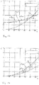
- Fig. 13 is the delivery height H, ie the pressure applied over the rotational speed n of the drive motor 30.
- Fig. 2 example there are three differential pressure values ⁇ P pre , ⁇ P hot and ⁇ P cold .
- the differential pressure ⁇ P pre is generated by the circulating pump unit 6 and can not be influenced by the mixing device 22 in this case, so that it is in Fig. 13 is shown as a constant, ie independent of the rotational speed of the drive motor 30 form.
- the impeller 26 of Umisselzpumpenaggregates 24 generates for the return of the underfloor heating 2 a differential pressure .DELTA.P cold and the impeller 28 generates for the flow from the supply line 18, a differential pressure .DELTA.P hot .
- the wheels 26 and 28 are formed differently, so they have different pressure gradients, ie different speed-dependent pressure gradients.
- the pressure curve for the impeller 28 is less steep than the pressure curve of the impeller 26. This can be achieved, for example, that the impeller 26 has a larger outer diameter.
- the differential pressures ⁇ P pre and ⁇ P hot are added , so that the pressure waveform ⁇ P hot is shifted upward by a constant value in the graph. This ensures that the pressure curve curves .DELTA.P hot and .DELTA.P cold intersect at a point 39. Above and below the point of intersection of these curves are mixing areas 40 for the mixed liquid.
- the output pressure of the impeller 28 is higher than that of the impeller 26, so that the output pressure of the impeller 28 in the flow path through the impeller 26 at the Mixing point 20 acts as a back pressure and hydraulic resistance and in this operating state, the flow through the first flow path through the impeller 26 is reduced and more heated heating medium is mixed to achieve a higher temperature in the flow 38 to the underfloor 2.
- Fig. 3 shows a further variant of a mixing device according to the invention or a heating system according to the invention, which differs from the heating system according to Fig. 2 differ in that no circulating pump unit 6 is provided in the flow 18. Ie. the heated heating medium is supplied via the supply line 18 without form the Ummélzpumpenaggregat 24. This results in the in Fig. 14 shown pressure curve curves. In Fig. 14 is in turn the delivery height H, ie the pressure applied over the rotational speed n of the drive motor 30. The pressure curve curves ⁇ P cold and ⁇ P hot correspond to the pressure curve curves , which in Fig. 13 are shown.
- this pressure difference between the pressure curve curves ⁇ P cold and ⁇ P hot (the mixing region 42) is speed-dependent.
- the hydraulic resistance, which acts in the flow path through the impeller 28 can be varied by changing the speed, so that the flow through the impeller 28 and thus the flow of heated heating medium can be changed. Even so, a change in the temperature on the output side of the mixing point 20 and thus a temperature control by changing the speed of the rotational speed n of the drive motor 30 is possible.
- Fig. 5 shows an embodiment which is a variant of in Fig. 2 illustrated embodiment represents.
- the two wheels 26 and 28 are formed in the form of a double impeller.
- the impeller 26 is formed by a first blade ring and the impeller 28 by a second blade ring of the same impeller.
- the variation of the mixing ratio at the mixing point 20 by changing the rotational speed n of the drive motor 30 takes place in the same way as with reference to FIG Fig. 3 and 13 described.
- a flow regulating valve R hot and in the return line 16 are additionally provided upstream of the wheels 26 and 28 in the flow line 18.
- the default setting is preferably carried out in such a way that initially the rotational speed of the drive motor 30 is set so that a sufficient flow is achieved by the bottom floor 2. Ie. it is the rotational speed of the wheels 26 and 28 initially adjusted so that a matched to the system, ie the hydraulic resistance of the system differential pressure is generated. Subsequently, the manual flow control valves R hot and R cold are adjusted so that at the given speed at the temperature sensor 36, a desired temperature setpoint value is reached.
- This temperature setpoint value can be, for example, a temperature setpoint value which is preset by a heating curve at the current outside temperature.
- Fig. 4 showed a third variant of a heating system with a mixing device according to the invention.
- a boiler 4 is provided with a downstream circulating pump unit 6.
- a floor heating 2 or a floor heating circuit 2 to be supplied is provided.
- a mixing device 44 is present in which a heating medium flow from a supply line 18 which extends from the boiler 4 is mixed with a heating medium flow from a return line 16 from the return of the floor heating 2.
- the mixing device 44 in turn has a circulation pump unit 46 with an electric drive motor 30.
- This drive motor 30 is also controlled in its rotational speed by a control device 34 which is integrated directly into the drive motor 30 or arranged directly in an electronics housing on the drive motor 30 can be.
- control device 34 is communicatively connected to a temperature sensor 36, which is located at a supply line 38 to the floor circuit 2 so that it detects the flow temperature of the heating medium which is supplied to the underfloor heating circuit 2.
- a temperature-dependent speed control can also be performed in the circulating pump unit 36 in the manner described above.
- the embodiment differs according to Fig. 4
- the circulatory pump unit does not have two parallel-connected impellers, but rather impeller parts 48 and 50 connected in series.
- the impeller parts 48 and 50 may be designed as two separate rotors which are connected to one another in a rotationally fixed manner so that they are rotationally driven via the common drive motor 30.
- the impeller parts 48, 50 are particularly preferably designed as an impeller, which has at least one second inlet opening in a radial middle area between a first central inlet opening and the outlet opening, as described in greater detail below.
- this second inlet opening forms the mixing or orifice point 52, at which the two liquid flows or heating medium flows from the return line 16 and the feed line 18 are mixed.
- the heating medium flow from the return line 16 experiences a first pressure increase ⁇ P1 upstream of the mixing point 52.
- the heating medium flow from the supply line 18 experiences a pressure increase ⁇ P pre through the circulation pump unit 6. which leaves the impeller part 48, injected.
- the orifice point 52 and the second impeller part 50 form a second flow path through which the heating medium flow from the supply line 18 and in the further course downstream of the mouth point 52 and the heating medium flow from the return line 16, which has previously experienced a pressure increase in a first flow path in the impeller part 48, flow.
- the mixed heating medium flow experiences a further pressure increase ⁇ P2.
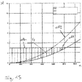
- Fig. 15 the pressure curves in the form of the delivery height H are plotted against the rotational speed n of the drive motor 30.
- ⁇ P pre the constant form pressure
- ⁇ P1 and ⁇ P2 are shown.
- the pressure curve .DELTA.P2 has a steeper course than the pressure curve .DELTA.P1, ie, the pressure .DELTA.P2 rises with increasing the speed more than the pressure .DELTA.P1.
- a mixing region 54 in which different mixing ratios can be realized.
- the hydraulic resistance increases in the second flow path to the impeller part 50 at the mixing point 52. It forms a back pressure at the mixing point 52, which serves as a hydraulic resistance for the Heating medium flow is used, which enters from the flow line 18 into the mixing point 52.
- This arrangement has the advantage that the pressure ⁇ P pre , which is generated by the circulating pump unit 6, does not have to be reduced since the mixture of the two heating medium flows takes place at a higher pressure level, namely at the level of the pressure ⁇ P1. As a result, energy losses in the mixing device 44 are reduced.
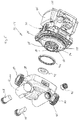
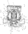
- FIGS. 6 to 12 The following is based on the FIGS. 6 to 12 the structural design of the mixing devices 22 and 44 described in more detail.
- the show FIGS. 6 to 9 a mixing device, which as a mixing device 22 in the embodiments according to Figures 2 . 3 and 5 is used.
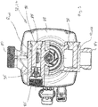
- the FIGS. 10 to 12 show a mixer 44, as in the embodiment according to Fig. 4 is used.
- the embodiment according to Fig. 6 to 9 shows an integrated circulation pump mixing device, ie a circulating pump unit with integrated mixing device or a mixing device with integrated circulation pump unit.
- the circulating pump unit has, in a known manner, an electric drive motor 30 to which an electronics housing or terminal box 56 is attached.
- the control device 34 is arranged in this embodiment.
- the electric drive motor has a stator or motor housing 58, inside which the stator 60 of the drive motor 30 is arranged.
- the stator 60 surrounds a gap pot or a can 62, which separates the stator space from a centrally located rotor space.
- In the rotor space of the rotor 64 is arranged, which may be formed for example as a permanent magnet rotor.
- the rotor 64 is connected via a rotor shaft 66 to the impeller 68, so that the rotor 64 rotatably drives the impeller 68 during its rotation about the rotation axis X.
- the impeller 68 is formed in this embodiment as a double impeller and combines the wheels 26 and 28, as they are based on Fig. 2 and 5 has been described.
- the impeller 68 has a central suction mouth 70, which opens into a first blade arrangement or a first blade ring, which forms the impeller 26.
- a first flow path through the impeller 68 is defined by the suction port 70 and the impeller 26.
- the impeller 26 is formed closed and has a front cover plate 72, which merges into a suction mouth 70 limiting collar.
- a second blade ring is arranged or formed, which forms the second impeller 28.
- the second impeller 28 has an annular suction port 74 on the inlet side, which annularly surrounds the suction port 70.
- the second suction port 74 forms a second inlet opening of the impeller 68.
- Both the impeller 26 and the impeller 28 have circumferentially outlet openings, which in a pressure chamber 76 of a Pump housing 78 open.
- the pump housing 78 is connected to the motor housing 58 in a conventional manner.
- the pressure chamber 76 in the interior of the pump housing 78 opens into a pressure port 80, which in accordance with in the embodiments Fig. 2 . 3 and 5 the supply line 38 would connect to the floor heating 2. Since both wheels 26 and 28 open into the pressure chamber 76, which is based on Fig. 2 . 3 and 5 described mixing point 20 exit side of the impeller 68 in the pressure chamber 76 of the pump housing 78th
- the first suction mouth 70 of the impeller 68 is in the pump housing 78 with a first suction line 82, which starts at a first suction port 84, in conjunction.
- This first suction nozzle 84 is axially aligned with the discharge nozzle 80 along an installation axis which extends normal to the axis of rotation X.
- the return line 16 is connected.
- a flow regulating valve R cold is disposed as shown in FIG Fig. 5 is shown.
- a first flow connection through the pump housing 78 is defined via the suction line 82, the suction port 70, the first impeller 26, the pressure chamber 76 and the discharge port 80.
- the pump housing 78 also has a second suction port 86, which forms a second input.
- the second suction nozzle is connected in the interior of the pump housing 78 via a connecting channel 88 with an annular space 90 on the suction side of the impeller 68.
- the annular space 90 surrounds a ring element 92 on the outside.
- the ring element 92 is inserted into the suction chamber of the pump housing 78 and engages with its annular collar with the collar surrounding the suction mouth 70, so that a sealed flow connection is created from the suction channel 82 into the suction mouth 70. Externally, the ring element 92 is surrounded by the annular space 90, so that the ring element 92 separates the flow path to the suction mouth 70 from the flow path to the second suction mouth 74. Inserted into the pump housing is also an annular sealing element 94, which abuts against the inner circumference of the pump housing 78 and sealingly comes into contact with the outer periphery of the impeller 68.
- a check valve 96 is also arranged, which prevents a backflow of liquid into the flow line 18.
- the flow line 18, as shown in the Fig. 2 . 3 and 5 shown is connected.
- the flow regulating valves R cold and R hot are formed as rotatable valve elements 98, which are each inserted into a cylindrical receiving space. By rotation, the valve elements 98 reach different degrees into the suction line 82 or cover the connecting channel 88, so that the free flow cross section in the first or second flow path can be changed by rotation of the corresponding valve element 98.
- the 10 to 12 show an embodiment of the Umisselzpumpenaggregates 46 with the mixing device 44, as shown by Fig. 4 and 15 has been described.
- the mixing device 44 and the circulation pump unit 46 also represent an integrated unit.
- the drive motor 30 with the attached electronics housing 56 corresponds in a structure to the drive motor 30, as it is based on the Fig. 7 till 9 has been described.
- the pump housing 78 'in its construction substantially corresponds to the above-described pump housing 78.
- a first difference is that the pump housing 78' has no flow control valves R hot and R cold , it being understood that in this second embodiment, such flow control valves R could be provided, as described above.
- a second difference is that the second suction port 86 'in this embodiment has an external thread. However, it should be understood that the suction port 86 could be configured according to the previous embodiment, or the Saugstutzten 86 'could also have an internal thread.
- an impeller 100 is connected to the rotor shaft 66.
- This impeller 100 has a central suction mouth 102, the peripheral edge of which is in sealing engagement with the ring member 92, so that a flow connection of the first suction port 84 is created in the impeller 100.
- the impeller 100 has only one blade ring, which defines a first flow path from the suction port 102, which forms a first inlet opening, to the outer periphery of the impeller 100. This first flow path opens into the pressure chamber 76, which is connected to the pressure port 80.
- Surrounding the ring element 92 is in turn an annular space 90, in which the connecting channel 88 opens from the second suction port 86.
- the impeller 100 has a front cover disk 104.
- openings 106 are formed, which form second inlet openings. These openings 106 open into the flow channels 108 between the impeller blades. In this case, the openings 106 open radially relative to the axis of rotation X seen in an area between the suction port 102 and the outer periphery of the impeller 100 in the flow channels 108. D. h. the openings 106 open into a radial middle region of the first flow path through the impeller 100.
- the openings 106 and the flow channels 108 form with their sections radially outside of the openings 106 form second flow paths, which the impeller part 50, as it is based on Fig. 4 has been described corresponds.
- the impeller part 78 is formed by the radially inner impeller part, ie in the flow direction between the suction mouth 102 and the openings 106.
- the openings 106 face the annular space 90, so that heating medium can enter via the connecting channel 88 into these openings 106.
- the outlet side of the openings 106 is thus in the flow channels 108 in this embodiment, the mixing point 52 according to Fig. 4 ,
- the impeller 100 has on its outer circumference, ie on the outer circumference of the cover plate 104 on an axially directed collar 110 which rests on the inner circumference of the pump housing 78 'and thus seals the annular space 90 relative to the pressure chamber 76.
- valves R hot or R cold may optionally be coupled to each other or be formed together as a three-way valve.
- An electric drive of these valves could by a common control device 34, which also the speed the drive motor 30 controls or be controlled to be controlled.
- the invention has been described using the example of a heating system. It should be understood, however, that the invention may equally be used in other applications in which two streams of liquid are to be mixed.
- One possible application is, for example, a system for setting a service water temperature, as is customary in pressure booster pumps for service water supply, in so-called shower booster pumps.
Landscapes
- Engineering & Computer Science (AREA)
- Physics & Mathematics (AREA)
- Thermal Sciences (AREA)
- Chemical & Material Sciences (AREA)
- Combustion & Propulsion (AREA)
- Mechanical Engineering (AREA)
- General Engineering & Computer Science (AREA)
- Steam Or Hot-Water Central Heating Systems (AREA)
Priority Applications (5)
| Application Number | Priority Date | Filing Date | Title |
|---|---|---|---|
| EP17184778.3A EP3438558A1 (fr) | 2017-08-03 | 2017-08-03 | Procédé de fonctionnement d'un dispositif mélangeur et ledit dispositif mélangeur |
| EP18746219.7A EP3662206A1 (fr) | 2017-08-03 | 2018-08-02 | Procédé pour faire fonctionner un dispositif de mélange ainsi que dispositif de mélange |
| US16/635,702 US20210164664A1 (en) | 2017-08-03 | 2018-08-02 | Method for operating a mixing device and mixing device |
| CN201880050291.1A CN110998195A (zh) | 2017-08-03 | 2018-08-02 | 用于运行混合装置的方法以及混合装置 |
| PCT/EP2018/070970 WO2019025527A1 (fr) | 2017-08-03 | 2018-08-02 | Procédé pour faire fonctionner un dispositif de mélange ainsi que dispositif de mélange |
Applications Claiming Priority (1)
| Application Number | Priority Date | Filing Date | Title |
|---|---|---|---|
| EP17184778.3A EP3438558A1 (fr) | 2017-08-03 | 2017-08-03 | Procédé de fonctionnement d'un dispositif mélangeur et ledit dispositif mélangeur |
Publications (1)
| Publication Number | Publication Date |
|---|---|
| EP3438558A1 true EP3438558A1 (fr) | 2019-02-06 |
Family
ID=59523020
Family Applications (2)
| Application Number | Title | Priority Date | Filing Date |
|---|---|---|---|
| EP17184778.3A Withdrawn EP3438558A1 (fr) | 2017-08-03 | 2017-08-03 | Procédé de fonctionnement d'un dispositif mélangeur et ledit dispositif mélangeur |
| EP18746219.7A Withdrawn EP3662206A1 (fr) | 2017-08-03 | 2018-08-02 | Procédé pour faire fonctionner un dispositif de mélange ainsi que dispositif de mélange |
Family Applications After (1)
| Application Number | Title | Priority Date | Filing Date |
|---|---|---|---|
| EP18746219.7A Withdrawn EP3662206A1 (fr) | 2017-08-03 | 2018-08-02 | Procédé pour faire fonctionner un dispositif de mélange ainsi que dispositif de mélange |
Country Status (4)
| Country | Link |
|---|---|
| US (1) | US20210164664A1 (fr) |
| EP (2) | EP3438558A1 (fr) |
| CN (1) | CN110998195A (fr) |
| WO (1) | WO2019025527A1 (fr) |
Families Citing this family (1)
| Publication number | Priority date | Publication date | Assignee | Title |
|---|---|---|---|---|
| CN118715375A (zh) | 2022-02-25 | 2024-09-27 | 格兰富控股联合股份公司 | 具有离心泵和混合单元的泵装置 |
Citations (4)
| Publication number | Priority date | Publication date | Assignee | Title |
|---|---|---|---|---|
| DE2116525A1 (de) * | 1971-04-05 | 1973-01-25 | Klein Schanzlin & Becker Ag | Warmwasser-sammelheizungsanlage |
| DE3724661A1 (de) * | 1987-07-25 | 1989-02-02 | Manfred Klenke | Vorrichtung zur beimischregelung in warmwasserheizungsanlagen |
| WO1997017575A1 (fr) * | 1994-09-21 | 1997-05-15 | Matti Ilmari Kangas | Systeme de chauffage par circulation de liquide et pompe associee |
| EP1191287A2 (fr) * | 2000-09-20 | 2002-03-27 | KSB Aktiengesellschaft | Système de tuyauterie pour l'échange d'énergie thermique |
Family Cites Families (11)
| Publication number | Priority date | Publication date | Assignee | Title |
|---|---|---|---|---|
| CH641889A5 (de) * | 1980-02-04 | 1984-03-15 | Landis & Gyr Ag | Heizungsanlage. |
| US6062485A (en) * | 1998-04-22 | 2000-05-16 | Erie Manufacturing Company | Radiant heating system reset control |
| DE102004059567B9 (de) * | 2004-12-09 | 2007-06-28 | Ari-Armaturen Albert Richter Gmbh & Co. Kg | Steuer- oder Regeleinrichtung zum Fördern und Mischen fluider Medien in Heizungs-, Brauch- oder Trinkwasseranlagen |
| CN201032221Y (zh) * | 2007-04-30 | 2008-03-05 | 陕西成明环保科技有限公司 | 采暖供热节能系统 |
| CN201262443Y (zh) * | 2008-08-25 | 2009-06-24 | 北京硕人时代科技有限公司 | 锅炉供热气候补偿系统 |
| CN201476141U (zh) * | 2009-05-19 | 2010-05-19 | 姚尚福 | 地暖空调混水全自动换热机组 |
| DE102010022763A1 (de) * | 2010-06-05 | 2011-12-08 | Oventrop Gmbh & Co. Kg | Verfahren zum automatischen hydraulischen Abgleich in fluidführenden Anlagen |
| CN202032674U (zh) * | 2011-03-21 | 2011-11-09 | 陈国永 | 一种用于地暖的智能温度控制装置 |
| PL2613097T5 (pl) * | 2012-01-09 | 2021-06-14 | Grundfos Holding A/S | Przyrząd grzejny |
| EP2871539B1 (fr) * | 2013-11-07 | 2019-04-17 | Grundfos Holding A/S | Procédé de diagnostic pour le diagnostic du fonctionnement correct d'un système de chauffage et/ou de refroidissement |
| EP2947325B1 (fr) * | 2014-05-23 | 2019-12-04 | Grundfos Holding A/S | Procédé de commande de pompe |
-
2017
- 2017-08-03 EP EP17184778.3A patent/EP3438558A1/fr not_active Withdrawn
-
2018
- 2018-08-02 US US16/635,702 patent/US20210164664A1/en not_active Abandoned
- 2018-08-02 CN CN201880050291.1A patent/CN110998195A/zh active Pending
- 2018-08-02 EP EP18746219.7A patent/EP3662206A1/fr not_active Withdrawn
- 2018-08-02 WO PCT/EP2018/070970 patent/WO2019025527A1/fr not_active Ceased
Patent Citations (4)
| Publication number | Priority date | Publication date | Assignee | Title |
|---|---|---|---|---|
| DE2116525A1 (de) * | 1971-04-05 | 1973-01-25 | Klein Schanzlin & Becker Ag | Warmwasser-sammelheizungsanlage |
| DE3724661A1 (de) * | 1987-07-25 | 1989-02-02 | Manfred Klenke | Vorrichtung zur beimischregelung in warmwasserheizungsanlagen |
| WO1997017575A1 (fr) * | 1994-09-21 | 1997-05-15 | Matti Ilmari Kangas | Systeme de chauffage par circulation de liquide et pompe associee |
| EP1191287A2 (fr) * | 2000-09-20 | 2002-03-27 | KSB Aktiengesellschaft | Système de tuyauterie pour l'échange d'énergie thermique |
Also Published As
| Publication number | Publication date |
|---|---|
| US20210164664A1 (en) | 2021-06-03 |
| EP3662206A1 (fr) | 2020-06-10 |
| CN110998195A (zh) | 2020-04-10 |
| WO2019025527A1 (fr) | 2019-02-07 |
Similar Documents
| Publication | Publication Date | Title |
|---|---|---|
| EP2078867B1 (fr) | Echangeur de pression destiné à la transmission d'énergie de pression d'un premier flux de liquide dans un deuxième flux de liquide | |
| EP3662205A1 (fr) | Dispositif de mélange et procédé de régulation de températion d'un écoulement de liquide | |
| EP3376038B1 (fr) | Groupe motopompe | |
| EP2871423B1 (fr) | Procédé de régulation pour un système de chauffage et/ou de refroidissement comprenant au moins un circuit de charge et dispositif de distribution pour un système de chauffage et/ou de refroidissement | |
| WO2018086886A1 (fr) | Pompe à liquide de refroidissement électrique | |
| WO2018167043A1 (fr) | Groupe motopompe | |
| EP3376050B1 (fr) | Groupe pompe centrifuge | |
| DE69512140T2 (de) | Durchflussregelventil und Heisswassererhitzer der dieses Ventil verwendet | |
| DE102010044167A1 (de) | Pumpe | |
| DE102014006258A1 (de) | Verfahren zur Regelung eines Pumpensystems und geregeltes Pumpensystem | |
| WO2019025525A1 (fr) | Unité de pompe de circulation | |
| EP3376051B1 (fr) | Groupe motopompe | |
| EP3376040B1 (fr) | Groupe motopompe | |
| EP3438558A1 (fr) | Procédé de fonctionnement d'un dispositif mélangeur et ledit dispositif mélangeur | |
| EP2455615B1 (fr) | Pompe | |
| WO2018158197A1 (fr) | Unité de pompe de circulation | |
| EP3376082B1 (fr) | Dispositif de soupape | |
| DE3207427A1 (de) | Verfahren und vorrichtung zum steuern des wassermengendurchlaufverhaeltnisses von kesselkreislauf zu heizkreislauf in warmwasserheizungsanlagen | |
| DE102011079897A1 (de) | Pumpe | |
| DE102017000201B4 (de) | Hydraulischer Lüfterantrieb, Arbeitsmaschine sowie Verfahren zum Betreiben eines Lüfterantriebs | |
| DE2134649A1 (de) | Umwälzpumpe fur Heiz oder Kuhlan lagen | |
| EP0169916A1 (fr) | Pompe, en particulier pompe pour direction assistée | |
| DE102005022160A1 (de) | Ölpumpe mit integrierter Stromregeleinrichtung | |
| DE102012021874A1 (de) | Motor-Pumpenbaugruppe | |
| EP2428745A2 (fr) | Bloc de chauffage électrique et chauffe-eau instantané |
Legal Events
| Date | Code | Title | Description |
|---|---|---|---|
| PUAI | Public reference made under article 153(3) epc to a published international application that has entered the european phase |
Free format text: ORIGINAL CODE: 0009012 |
|
| STAA | Information on the status of an ep patent application or granted ep patent |
Free format text: STATUS: THE APPLICATION HAS BEEN PUBLISHED |
|
| AK | Designated contracting states |
Kind code of ref document: A1 Designated state(s): AL AT BE BG CH CY CZ DE DK EE ES FI FR GB GR HR HU IE IS IT LI LT LU LV MC MK MT NL NO PL PT RO RS SE SI SK SM TR |
|
| AX | Request for extension of the european patent |
Extension state: BA ME |
|
| STAA | Information on the status of an ep patent application or granted ep patent |
Free format text: STATUS: REQUEST FOR EXAMINATION WAS MADE |
|
| 17P | Request for examination filed |
Effective date: 20190806 |
|
| RBV | Designated contracting states (corrected) |
Designated state(s): AL AT BE BG CH CY CZ DE DK EE ES FI FR GB GR HR HU IE IS IT LI LT LU LV MC MK MT NL NO PL PT RO RS SE SI SK SM TR |
|
| STAA | Information on the status of an ep patent application or granted ep patent |
Free format text: STATUS: EXAMINATION IS IN PROGRESS |
|
| 17Q | First examination report despatched |
Effective date: 20201209 |
|
| STAA | Information on the status of an ep patent application or granted ep patent |
Free format text: STATUS: THE APPLICATION IS DEEMED TO BE WITHDRAWN |
|
| 18D | Application deemed to be withdrawn |
Effective date: 20210622 |