EP3438762A2 - Uhrwerkoszillator mit flexiblen führungen mit grosser winkelförmiger laufbahn - Google Patents
Uhrwerkoszillator mit flexiblen führungen mit grosser winkelförmiger laufbahn Download PDFInfo
- Publication number
- EP3438762A2 EP3438762A2 EP18185138.7A EP18185138A EP3438762A2 EP 3438762 A2 EP3438762 A2 EP 3438762A2 EP 18185138 A EP18185138 A EP 18185138A EP 3438762 A2 EP3438762 A2 EP 3438762A2
- Authority
- EP
- European Patent Office
- Prior art keywords
- blade
- blades
- plane
- oscillation
- flexible
- Prior art date
- Legal status (The legal status is an assumption and is not a legal conclusion. Google has not performed a legal analysis and makes no representation as to the accuracy of the status listed.)
- Pending
Links
Images


Classifications
-
- G—PHYSICS
- G04—HOROLOGY
- G04B—MECHANICALLY-DRIVEN CLOCKS OR WATCHES; MECHANICAL PARTS OF CLOCKS OR WATCHES IN GENERAL; TIME PIECES USING THE POSITION OF THE SUN, MOON OR STARS
- G04B31/00—Bearings; Point suspensions or counter-point suspensions; Pivot bearings; Single parts therefor
-
- G—PHYSICS
- G04—HOROLOGY
- G04B—MECHANICALLY-DRIVEN CLOCKS OR WATCHES; MECHANICAL PARTS OF CLOCKS OR WATCHES IN GENERAL; TIME PIECES USING THE POSITION OF THE SUN, MOON OR STARS
- G04B17/00—Mechanisms for stabilising frequency
- G04B17/04—Oscillators acting by spring tension
- G04B17/045—Oscillators acting by spring tension with oscillating blade springs
-
- B—PERFORMING OPERATIONS; TRANSPORTING
- B81—MICROSTRUCTURAL TECHNOLOGY
- B81B—MICROSTRUCTURAL DEVICES OR SYSTEMS, e.g. MICROMECHANICAL DEVICES
- B81B3/00—Devices comprising flexible or deformable elements, e.g. comprising elastic tongues or membranes
- B81B3/0035—Constitution or structural means for controlling the movement of the flexible or deformable elements
- B81B3/004—Angular deflection
- B81B3/0045—Improve properties related to angular swinging, e.g. control resonance frequency
-
- G—PHYSICS
- G04—HOROLOGY
- G04B—MECHANICALLY-DRIVEN CLOCKS OR WATCHES; MECHANICAL PARTS OF CLOCKS OR WATCHES IN GENERAL; TIME PIECES USING THE POSITION OF THE SUN, MOON OR STARS
- G04B31/00—Bearings; Point suspensions or counter-point suspensions; Pivot bearings; Single parts therefor
- G04B31/02—Shock-damping bearings
Definitions
- the invention relates to a clockwork mechanical oscillator comprising, between a rigid support member and a solid inertial element, a flexible guide with at least two first flexible blades which support said massive inertial element and are arranged to return it to a rest position.
- said solid inertial element being arranged to oscillate angularly along a plane of oscillation around said rest position, said two first flexible blades not touching each other and their projections on said oscillation plane intersecting, in the rest position, a point of intersection, in the immediate vicinity of which or through which the axis of rotation of said solid inertial element perpendicular to said plane of oscillation passes, and the recesses of said first flexible blades with said rigid support element and said massive inertial element defining at least two directions of blades parallel to said plane of oscillation.
- the invention also relates to a watch movement comprising at least one such mechanical oscillator.
- the invention also relates to a watch comprising such a clockwork movement.
- the invention relates to the field of mechanical clockwork oscillators comprising flexible blade guides providing the functions of holding and recall of moving elements.
- flexible guides particularly with flexible blades, in mechanical clock oscillators
- methods of production such as "MEMS", “LIGA” or similar, of micro-machinable materials, such as silicon and its oxides, which allow a very reproducible manufacture of components that have constant elastic characteristics over time and a high insensitivity to external agents such as temperature and humidity.
- Flexible guide pins as described in the applications EP1419039 or EP16155039 of the same depositor, allow in particular to replace the pivot of a conventional balance wheel, and the spiral spring which is usually associated. The elimination of the friction of pivots makes it possible to increase substantially the quality factor of an oscillator.
- the flexible guide pins generally have a small angular travel, of the order of 10 ° to 20 °, which is very low compared to the usual amplitude of 300 ° of a balance-spring, and which not allow their direct combination with conventional exhaust mechanisms, including conventional stoppers such as a Swiss anchor or the like, which require a large angular stroke to ensure their proper operation.
- the document EP3035127A1 in the name of the same applicant SWATCH GROUP RESEARCH & DEVELOPMENT Ltd describes a watch oscillator comprising a time base with at least one resonator constituted by a tuning fork which comprises at least two oscillating mobile parts, said movable parts being fixed to a connecting element , which comprises said oscillator, by flexible elements whose geometry determines a virtual pivot axis of position determined with respect to said connecting element, about which virtual pivot axis oscillates said respective moving part, whose center of mass is merged into position resting with said respective virtual pivot axis.
- said flexible elements consist of crossed elastic blades and extending at a distance from one another in two parallel planes, and whose projections of the directions on one of said parallel planes intersect at the same level.
- said virtual pivot axis, said movable part considered.
- the document US3628781A in the name of GRIB describes a tuning fork, in the form of a double cantilevered structure, to allow an increased rotational movement of a pair of moving elements, relative to a fixed reference plane
- a tuning fork in the form of a double cantilevered structure, to allow an increased rotational movement of a pair of moving elements, relative to a fixed reference plane
- a first resiliently-deformable body having at least two elastically-like elongated flexible portions, the ends of each of said flexible portions respectively being secured to enlarged rigid portions of said member, the first of said rigid portions being fixed to define a reference plane and the second being supported elastically to have an increased rotational movement with respect to the first, a second deformable body elastically substantially identical to the first deformable body resiliently, and means for rigidly securing the first of said respective rigid portions of said elastically deformable bodies in spaced relation to provide a tuning fork structure in which each of the tuning fork teeth comprises the free end of one of said elastic
- the document EP3130966A1 in the name of ETA Manufacture Horlogère Suisse describes a mechanical watchmaking movement that includes at least one barrel, a set of gear wheels driven at one end by the barrel, and a mechanism of escape of a local oscillator with a resonator in the form of a balance-spring and a feedback system of the watch movement.
- the exhaust mechanism is driven to another end of the set of gear wheels.
- the feedback system includes at least one accurate reference oscillator, combined with a step comparator for comparing the operation of the two oscillators, and a local oscillator resonator tuning mechanism for slowing or accelerating the resonator based on the oscillator. a result of the comparison in the walking comparator.
- the document CH709536A2 in the name of ETA Manufacture Horlogère Suisse describes a watchmaking mechanism comprising, mounted mobile, at least pivotally relative to a plate, an escape wheel arranged to receive a motor torque via a train, and a first oscillator comprising a first rigid structure connected to said plate by first elastic return means.
- This regulator mechanism comprises a second oscillator comprising a second rigid structure connected to said first rigid structure by second elastic return means, and which comprises guide means arranged to cooperate with complementary guiding means that comprises said escape wheel, synchronizing said first oscillator and said second oscillator with said wheel.
- the invention proposes to develop a mechanical oscillator with flexible guides, whose angular travel is compatible with existing exhaust mechanisms, and whose flexible guides behave regularly regardless of their deformation.
- the invention relates to a mechanical oscillator according to claim 1.
- the invention also relates to a watch movement comprising at least one such mechanical oscillator.
- the invention also relates to a watch comprising such a clockwork movement.
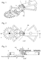
- the invention relates to a mechanical clock oscillator 100, comprising at least one rigid support element 4 fixed directly or indirectly to a plate 900, and a solid inertial element 5.
- This oscillator 100 comprises, between the rigid support element 4 and the solid inertial element 5, a flexible guide mechanism 200.
- This flexible guide mechanism comprises at least two first flexible blades 31, 32, which support the solid inertial element 5 and are arranged to return it to a rest position.
- This massive inertial element 5 is arranged to oscillate angularly according to a plane of oscillation around this rest position.
- the first two flexible blades 31 and 32 do not touch each other, and, in the rest position, their projections on the plane of oscillation intersect at a point of intersection P, in the immediate vicinity of which or through which the axis of rotation passes.
- the massive inertial element 5 perpendicular to the plane of oscillation. All the geometric elements described below mean, unless otherwise stated, as considered in the rest position of the oscillator stopped.
- FIGS. 1 to 4 illustrate a first variant with a rigid support element 4 and a massive inertial element connected by two first flexible blades 31, 32.
- the embedding of the first flexible blades 31, 32, with the rigid support element 4 and the solid inertial element 5 define at least two directions of blades DL1, DL2, which are parallel to the plane of oscillation and which are in projection on the plane of oscillation, an angle at the apex ⁇ .
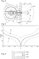
- the value of the ratio D / L is between 0 and 1, and the apex angle ⁇ is less than or equal to 70 °.
- both the angle at the apex ⁇ is less than or equal to 60 °, and, for each first flexible blade 31, 32, the embedding ratio D1 / L1, D2 / L2 is between 0.15 and 0.85, terminals included.
- the center of mass of the oscillator 100 in its rest position is distant from the crossover point P a difference ⁇ which is between 10% and 20% of the total length L of the projection, on the plane of oscillation, of the blade 31, 32. More particularly, the difference ⁇ is between 12% and 18% of the total length L of the projection, on the plane of oscillation, of the blade 31, 32.
- the first blades 31, 32, and their recesses together define a pivot 1 which, in projection on the plane of oscillation, is symmetrical with respect to an axis of symmetry AA passing through the crossing point P.
- the center of mass of the massive inertial element 5 is located on the axis of symmetry AA of the pivot 1. In projection, this center of mass can be confused or not with the crossover point P.
- the center of mass of the massive inertial element 5 is situated at a non-zero distance from the point of intersection P corresponding to the axis of rotation of the massive inertial element 5, as visible on the Figures 2 to 4 .
- the center of mass of the massive inertial element 5 is located on the axis of symmetry AA of the pivot 1, and is situated at a non-zero distance from the crossover point P of which is between 0.1 times and 0.2 times the total length L of the projection, on the plane of oscillation, of the blade 31, 32.
- the first blades 31 and 32 are straight blades.
- the apex angle ⁇ is less than or equal to 50 °, or is less than or equal to 40 °, or less than or equal to 35 °, or even less than or equal to 30 °.
- the embedding ratio D1 / L1, D2 / L2 is between 0.15 and 0.49, including terminals, or between 0.51 and 0.85, including terminals, as visible on the figure 5 .
- the apex angle ⁇ is less than or equal to 50 °
- the embedding ratio D1 / L1, D2 / L2 is between 0.25 and 0.75, inclusive.
- the apex angle ⁇ is less than or equal to 40 °
- the embedding ratio D1 / L1, D2 / L2 is between 0.30 and 0.70, inclusive.
- the apex angle ⁇ is less than or equal to 35 °
- the embedding ratio D1 / L1, D2 / L2 is between 0.40 and 0.60, including terminals.
- the first flexible blades 31 and 32 have the same length L, and the same distance D.
- these first flexible blades 31 and 32 are identical.
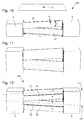
- FIGS. 6 to 8 illustrate a second variant of mechanical oscillator 100, wherein the rigid support element 4 is also movable, directly or indirectly with respect to a fixed structure that this oscillator 100 comprises, and is carried by a third rigid element 6, via two second flexible blades 33, 34, arranged similarly to the first flexible blades 31, 32.
- the projections of the first flexible blades 31, 32, and second flexible blades 33, 34, on the oscillation plane intersect at the same crossover point P.
- the projections of the first flexible blades 31, 32, and second flexible blades 33, 34, on the oscillation plane. intersect at two distinct points both located on the axis of symmetry AA of the pivot 1, when the pivot 1 is symmetrical with respect to the axis of symmetry AA.
- the embedding of the second flexible blades 33, 34, with the rigid support element 4 and the third rigid element 6, define two directions of blades parallel to the plane of oscillation and forming between them, in projection on the plane of oscillation, an angle at the apex of the same bisector as the angle ⁇ at the top that the first flexible blades 31, 32. More particularly, these two directions of the second flexible blades 33, 34 have the same angle at the top ⁇ as the first flexible blades 31, 32.
- the second flexible blades 33, 34 are identical to the first flexible blades 31, 32, as in the non-limiting example of the figures.
- the center of mass of the massive inertial element 5 is located on the axis of symmetry AA of the pivot 1.
- both the mass center of the massive inertial element 5 and the center of mass of the rigid support element 4 are located on the axis of symmetry AA of the pivot 1. More particularly, the projections of the center of mass of the massive inertial element 5 and the center of mass of the rigid support element 4, on the axis of symmetry AA of the pivot 1, are confused.
- a particular configuration illustrated by the figures for such superposed pivots is that where the projections of the first flexible blades 31, 32, and second flexible blades 33, 34, on the oscillation plane intersect at the same point of intersection P, which also corresponds to the projection of the center of mass of the massive inertial element 5, or at least which is as close as possible to it. More particularly, this same point also corresponds to the projection of the center of mass of the rigid support element 4. More particularly, this same point also corresponds to the projection of the center of mass of the entire oscillator 100.
- the mass center of the massive inertial element 5 is located, in projection on the plane of oscillation, on the axis of symmetry AA of the pivot 1 and at a non-zero distance from the point of intersection corresponding to the axis of rotation of the rigid support element 4 which non-zero distance is between 0.1 times and 0.2 times the total length L of the projection, on the plane of oscillation, of the blade 31, 32.
- the center of mass of the rigid support element 4 is located, in projection on the plane of oscillation, on the axis of symmetry AA of the pivot 1 and at a non-zero distance from the crossing point P corresponding to the axis of rotation of the massive inertial element 5.
- this non-zero distance is between 0.1 times and 0.2 times the total length L of the projecting, on the plane of oscillation, the blade 33, 34.
- the center of mass of the rigid support element 4 is located, in projection on the plane of oscillation, on the axis of symmetry AA of the pivot 1 and at a non-zero distance from the point of intersection corresponding to the axis of rotation of the rigid support element 4 which non-zero distance is between 0.1 times and 0.2 times the total length L of the projection, on the plane of oscillation, of the blade 31, 32.
- the center of mass of the rigid support member 4 is located on the axis of symmetry AA of the pivot 1 and the non-zero distance of the crossover point P which is between 0.1 times and 0.2 times the total length L of the projection, on the plane of oscillation, of the blade 33, 34.
- the massive inertial element 5 is elongate in the direction of the axis of symmetry AA of the pivot 1, when the pivot 1 is symmetrical with respect to the axis of symmetry AA.
- the inertial element 5 comprises a base on which is fixed a traditional long-arm balancer provided with sections of serge or flyweights in an arc.
- the objective is to minimize the influence of external angular accelerations around the axis of symmetry of the pivot, because the blades have a low rigidity in rotation around this axis because of the small angle ⁇ .
- the invention lends itself well to a monolithic execution of the blades and the solid components they join, made of micro-machinable material or at least partially amorphous, with an implementation by "MEMS" or "LIGA” method or the like.
- the oscillator 100 is advantageously thermally compensated by adding silicon dioxide to flexible silicon strips.
- the blades can be assembled, for example embedded in grooves, or other.
- the illustrated variants comprise all pivot axes, blade crossings, and mass centers, coplanar, which is a special case that is advantageous, but not limiting.
- each of the elementary blades has an aspect ratio limited to a threshold value.
- the aspect ratio of each elementary plate is reduced to find the optimum of isochronism and insensitivity to the positions.
- the oscillator 100 comprises a first number N1 of first blades called primary blades 31 extending in a first blade direction DL1, and a second number N2 of first secondary blades 32 extending in a second blade direction DL2 the first number N1 and the second number N2 each being greater than or equal to two.
- the first number N1 is equal to the second number N2.
- the oscillator 100 comprises at least one pair formed of a primary blade 31 extending in a first blade direction DL1, and a secondary blade 32 extending in a second blade direction DL2. And, in each pair, the primary blade 31 is identical to the secondary blade 32 in the orientation.
- the oscillator 100 has only pairs each formed of a primary blade 31 extending in a first blade direction DL1, and a secondary blade 32 extending in a second blade direction DL2 and in each pair, the primary blade 31 is identical to the secondary blade 32 in the orientation.
- the oscillator 100 comprises at least one group of blades formed of a primary blade 31 extending in a first blade direction DL1, and a plurality of secondary blades 32 extending in a second direction DL2 blade direction. And, in this case, in each group of blades, the elastic behavior of the primary blade 31 is identical to the elastic behavior resulting from the accumulation of the plurality of secondary blades 32 to the orientation.
- the invention also relates to a watch movement 1000 comprising at least one such mechanical oscillator 100.
- the invention also relates to a watch 2000 comprising at least one such watch movement 1000.
- DRIE Deep Reactive Ion Etching
- Standard methods of manufacturing by DRIE etching of silicon do not yet make it easy to manufacture a monolithic pivot having more than two distinct levels. It is therefore easier to manufacture separate parts which are then assembled.
- the sensitivity to assembly errors requires a precision greater than one micrometer, to obtain the optimal properties of isochronism and / or insensitivity to the positions. In order to solve this problem, it is necessary to adopt a manufacturing strategy which is described below.
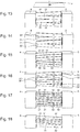
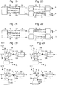
- the invention proposes to dividing the flexible guide, or pivot, into subunits composed of two-blade pivots, for example an upper subunit and a lower subunit, in the case of a flexible guide comprising four blades, as visible on the figure 19 , with four alternate blades, which is broken down into two subunits of two-blade pivots.
- the Figures 21 and 22 illustrate a similar decomposition in the case of framed blades rather than alternate blades.
- Each subunit is manufactured by two-level DRIE etching (SOI wafer attacked from above and below) to ensure sufficient alignment accuracy.
- the upper subunit is then assembled to the lower subunit.
- This assembly can be performed by any conventional method: alignment pinning and screwing, or bonding, or "wafer fusion bonding", or solder, or solder, or any other method known to those skilled in the art.
- the mechanism comprises at least one translation table, whose free movement can absorb the disagreement between the two rotations of separate axes. At least one of the translation tables must be sufficiently flexible so that the movement mismatch does not degrade the isochronism. In the case where two identical translation tables are introduced, as shown in FIG. figure 23 they must be sufficiently flexible so that the motion discrepancy does not degrade the isochronism, and sufficiently rigid so that the position of the pivot is well determined.
- the flexible guiding mechanism 200 comprises, superimposed on one another, at least one upper stage 28 and at least one lower stage 29.
- the upper subunit comprises an upper stage 28, which comprises, between an upper support 48 and an upper inertial element 58, at least one upper primary blade 318 extending in a first upper blade direction DL1S and an upper secondary blade 328. extending in a second upper blade direction DL2S, intersected in projection at an upper crossing point PS.
- the lower subunit comprises a lower stage 29, which comprises, between a lower support 49 and a lower inertial element 59, at least one lower primary blade 319 extending in a first lower blade direction DL1I and a lower secondary blade 329. extending in a second lower blade direction DL2I crossed in projection at a lower crossover point PI, at rest at the upper crossover point PS of a difference ⁇ .
- At least the upper stage 28 or the lower stage 29 comprises, between the plate 900 and the upper support 48, or respectively the lower support 49, an upper translation table 308, or respectively a lower translation table 309, which has at least one elastic connection which allows the translation along one or two axes of freedom in the plane of oscillation, and whose translational stiffness along these two axes is less than that of each flexible blade 31, 32, 333, 34, 318, 319, 328, 329, which comprises the flexible guide mechanism 200.
- the upper directions DL1S and DL2S of the upper stage 28 are identical to the lower directions DL1I and DL2I of the lower stage 29. Preferably, they have the same bisectors.
- the point P through which the axis of rotation of the inertial element 5 passes is situated between the upper point of intersection PS and the lower point of intersection P1, exactly in the middle if the flexible guide mechanism 200 comprises two tables. higher translations 308 and lower 309 which are identical.
- this point P is located exactly on the lower crossing point PI if the lower stage 29 does not have a translation table, or on the upper point of intersection PS if the upper stage 28 does not have a table translation.
- the oscillator 100 comprises, for each flexible guide mechanism 200 that it comprises, a massive inertial element 5 is unique. More particularly, the flexible guide mechanism 200 is unique, and the solid inertial element 5 is unique.
- translation tables 308 and 309 illustrated by the figures is not limiting. These translation tables 308 and 309 can also be between the inertial element 5 and the recesses of the inertial element side.
- the combination of the tables in translation, along the X axis and along the Y axis must be more flexible than the flexible pivot according to the same axes. This rule is valid regardless of the number of stages, the cumulation due to the combination of all the tables, in translation, along the X axis and along the Y axis, must be more flexible than the flexible pivot.
- the elastic connection of the upper translation table 308, or respectively of the lower translation table 309, along one or two axes of freedom in the oscillation plane, is thus preferably an elastic connection along these axes X and Y.
- the upper stage 28 and the lower stage 29 each comprise, between the plate 900 and the upper support 48, and respectively the lower support 49, an upper translation table 308, or respectively a lower translation table 309, comprising at least one elastic connection in one or two axes of freedom in the plane of oscillation, and whose stiffness is less than that of each flexible blade.
- An alternative is to use two different translation tables, the first being flexible so that the movement mismatch does not degrade the isochronism, and the second is rigid to ensure the positioning of the pivot.
- one stage may comprise a translation table, and the other stage may have a rigid attachment
- the upper inertial element 58 and the lower inertial element 59 constitute all or part of the massive inertial element 5, and are rigidly connected, directly or indirectly, to each other.
- the upper support 48 and the lower support 49 are connected, as appropriate, directly or through an upper translation table 308, or respectively a lower translation table 309, to an upper rigid part 480, respectively a lower rigid portion 490, which are rigidly connected to the rigid support member 4, or to the plate 900.
- An upper translation table 308 comprises, between the upper support 48 and an upper intermediate mass 68, first flexible elastic links 78 extending in the direction X, and, between the upper intermediate mass 68 and the upper rigid portion 480, second flexible elastic links 88 extending in the direction Y.
- a lower translation table 309 comprises, between the lower support 49 and a lower intermediate mass 69, first flexible elastic links 79 extending in the direction X and, between the lower intermediate mass 69 and the lower rigid portion 490, second resilient flexible links 89 extending in the Y direction.
- each translation table contributes to the protection of the mechanism against strong accelerations, during a fall or percussion for example.
- This particular arrangement with at least one translation table makes it possible, in short, to guarantee the alignment between the upper and lower stages, and to avoid the large stresses that the blades would suffer if the upper and lower stages did not follow the same trajectory. .
- Yet another alternative is to equip the mechanism with an upper translation table 308 and a lower translation table 309, with an upper support 48 and a lower support 49 which are no longer rigidly connected to the rigid support element 4, or platinum 900, but which are forced to planar movements, inverse X and Y, by a crankshaft type connection or the like, with respect to a fixed axis of the rigid support element 4, or platinum 900
- This solution has the advantage of allowing the anisochronism to be adjusted without slightly displacing the axis of rotation of the resonator.
- the figure 28 illustrates a simplified example with a translation table with collar connection: the upper support 48 is connected to an intermediate element 488 suspended by a first elastic neck 880 to a second intermediate element 889 to a second neck 890 which performs the elastic connection with the lower rigid portion 490, rigidly connected to the plate 900.
- the upper inertial element 58 and the lower inertial element 59 are connected to another intermediate element 589 to constitute with it the massive inertial element 5.
Landscapes
- Physics & Mathematics (AREA)
- General Physics & Mathematics (AREA)
- Engineering & Computer Science (AREA)
- Computer Hardware Design (AREA)
- Microelectronics & Electronic Packaging (AREA)
- Micromachines (AREA)
- Electric Clocks (AREA)
Priority Applications (7)
| Application Number | Priority Date | Filing Date | Title |
|---|---|---|---|
| EP18185138.7A EP3438762A3 (de) | 2017-07-28 | 2018-07-24 | Uhrwerkoszillator mit flexiblen führungen mit grosser winkelförmiger laufbahn |
| EP18205260.5A EP3561607B1 (de) | 2018-04-23 | 2018-11-08 | Stossdämpfungsschutz eines resonatormechanismus mit flexibler drehführung |
| JP2019124349A JP6843191B2 (ja) | 2018-07-24 | 2019-07-03 | 長い角ストロークを有するフレクシャーベアリングを備えた計時器用発振器 |
| US16/511,191 US10935933B2 (en) | 2018-07-24 | 2019-07-15 | Timepiece oscillator with flexure bearings having a long angular stroke |
| CN201910670433.0A CN110780572B (zh) | 2018-07-24 | 2019-07-24 | 机械钟表振荡器以及包括其的钟表机芯和手表 |
| JP2019195910A JP6828117B2 (ja) | 2018-04-23 | 2019-10-29 | 回転式の撓み支持体を備えた共振機構のための衝撃に対する保護 |
| CN201911081303.XA CN111158230B (zh) | 2018-04-23 | 2019-11-07 | 用于具有旋转柔性轴承的谐振器机构的抗震保护 |
Applications Claiming Priority (3)
| Application Number | Priority Date | Filing Date | Title |
|---|---|---|---|
| EP17183666.1A EP3435170B1 (de) | 2017-07-28 | 2017-07-28 | Uhrwerkoszillator mit flexiblen führungen mit grosser winkelförmiger laufbahn |
| EP18179623.6A EP3451073B1 (de) | 2017-07-28 | 2018-06-25 | Uhrwerkoszillator mit flexiblen führungen mit grosser winkelförmiger laufbahn |
| EP18185138.7A EP3438762A3 (de) | 2017-07-28 | 2018-07-24 | Uhrwerkoszillator mit flexiblen führungen mit grosser winkelförmiger laufbahn |
Publications (2)
| Publication Number | Publication Date |
|---|---|
| EP3438762A2 true EP3438762A2 (de) | 2019-02-06 |
| EP3438762A3 EP3438762A3 (de) | 2019-03-13 |
Family
ID=68137772
Family Applications (1)
| Application Number | Title | Priority Date | Filing Date |
|---|---|---|---|
| EP18185138.7A Pending EP3438762A3 (de) | 2017-07-28 | 2018-07-24 | Uhrwerkoszillator mit flexiblen führungen mit grosser winkelförmiger laufbahn |
Country Status (1)
| Country | Link |
|---|---|
| EP (1) | EP3438762A3 (de) |
Cited By (4)
| Publication number | Priority date | Publication date | Assignee | Title |
|---|---|---|---|---|
| CN112711183A (zh) * | 2019-10-24 | 2021-04-27 | 斯沃奇集团研究和开发有限公司 | 用于枢转质量块的枢转引导装置和钟表谐振器机构 |
| CN114428447A (zh) * | 2020-10-29 | 2022-05-03 | 斯沃奇集团研究及开发有限公司 | 用于旋转谐振器机构的具有平移台的柔性引导件,尤其用于钟表机芯 |
| EP3992728A1 (de) * | 2020-10-29 | 2022-05-04 | The Swatch Group Research and Development Ltd | Flexible führung mit verschiebetisch für einen rotierenden resonatormechanismus, insbesondere eines uhrwerks |
| EP4191346A1 (de) * | 2021-12-06 | 2023-06-07 | The Swatch Group Research and Development Ltd | Stossdämpfungsschutz eines resonatormechanismus mit flexibler drehführung |
Citations (5)
| Publication number | Priority date | Publication date | Assignee | Title |
|---|---|---|---|---|
| US3628781A (en) | 1969-10-03 | 1971-12-21 | Philamon Inc | Compound tine for tuning fork or the like |
| EP1419039A1 (de) | 2000-10-03 | 2004-05-19 | Dan Appels Engineering BV | Verfahren und vorrichtung zur wiederverwendung von bitumenhaltigen materialien, insbesondere bitumenhaltigen dachmaterialien |
| CH709536A2 (fr) | 2014-02-17 | 2015-10-15 | Eta Sa Manufacture Horlogère Suisse | Mécanisme régulateur d'horlogerie comportant deux oscillateurs. |
| EP3035127A1 (de) | 2014-12-18 | 2016-06-22 | The Swatch Group Research and Development Ltd. | Stimmgabeloszillator einer stimmgabelgesteuerten Uhr |
| EP3130966A1 (de) | 2015-08-11 | 2017-02-15 | ETA SA Manufacture Horlogère Suisse | Mechanisches uhrwerk, das mit einem bewegungsrückkopplungssysteme ausgestattet ist |
Family Cites Families (3)
| Publication number | Priority date | Publication date | Assignee | Title |
|---|---|---|---|---|
| EP3457221B1 (de) * | 2014-09-16 | 2022-08-10 | Patek Philippe SA Genève | Oszillator einer uhr mit flexiblem zapfen |
| EP3324247B1 (de) * | 2016-11-16 | 2019-11-27 | The Swatch Group Research and Development Ltd | Schutz der platten eines resonators einer mechanischen armbanduhr |
| EP3327515B1 (de) * | 2016-11-23 | 2020-05-06 | ETA SA Manufacture Horlogère Suisse | Sich drehender resonator mit einer flexiblen führung, der von einer freien ankerhemmung gehalten wird |
-
2018
- 2018-07-24 EP EP18185138.7A patent/EP3438762A3/de active Pending
Patent Citations (5)
| Publication number | Priority date | Publication date | Assignee | Title |
|---|---|---|---|---|
| US3628781A (en) | 1969-10-03 | 1971-12-21 | Philamon Inc | Compound tine for tuning fork or the like |
| EP1419039A1 (de) | 2000-10-03 | 2004-05-19 | Dan Appels Engineering BV | Verfahren und vorrichtung zur wiederverwendung von bitumenhaltigen materialien, insbesondere bitumenhaltigen dachmaterialien |
| CH709536A2 (fr) | 2014-02-17 | 2015-10-15 | Eta Sa Manufacture Horlogère Suisse | Mécanisme régulateur d'horlogerie comportant deux oscillateurs. |
| EP3035127A1 (de) | 2014-12-18 | 2016-06-22 | The Swatch Group Research and Development Ltd. | Stimmgabeloszillator einer stimmgabelgesteuerten Uhr |
| EP3130966A1 (de) | 2015-08-11 | 2017-02-15 | ETA SA Manufacture Horlogère Suisse | Mechanisches uhrwerk, das mit einem bewegungsrückkopplungssysteme ausgestattet ist |
Non-Patent Citations (1)
| Title |
|---|
| LARRY L. HOWELL: "Handbook of compilant mechanisms", WILEY |
Cited By (12)
| Publication number | Priority date | Publication date | Assignee | Title |
|---|---|---|---|---|
| CN112711183A (zh) * | 2019-10-24 | 2021-04-27 | 斯沃奇集团研究和开发有限公司 | 用于枢转质量块的枢转引导装置和钟表谐振器机构 |
| EP3812842A1 (de) * | 2019-10-24 | 2021-04-28 | The Swatch Group Research and Development Ltd | Schwenkbare führungsvorrichtung für eine schwenkbare masse, und resonatormechanismus einer uhr |
| JP2021067685A (ja) * | 2019-10-24 | 2021-04-30 | ザ・スウォッチ・グループ・リサーチ・アンド・ディベロップメント・リミテッド | 枢動質量体のための枢動案内デバイス及び計時器共振器機構 |
| JP7021326B2 (ja) | 2019-10-24 | 2022-02-16 | ザ・スウォッチ・グループ・リサーチ・アンド・ディベロップメント・リミテッド | 枢動質量体のための枢動案内デバイス及び計時器共振器機構 |
| CN112711183B (zh) * | 2019-10-24 | 2022-04-12 | 斯沃奇集团研究和开发有限公司 | 用于枢转质量块的枢转引导装置和钟表谐振器机构 |
| US11789407B2 (en) | 2019-10-24 | 2023-10-17 | The Swatch Group Research And Development Ltd | Pivoting guide device for a pivoting mass and timepiece resonator mechanism |
| CN114428447A (zh) * | 2020-10-29 | 2022-05-03 | 斯沃奇集团研究及开发有限公司 | 用于旋转谐振器机构的具有平移台的柔性引导件,尤其用于钟表机芯 |
| EP3992728A1 (de) * | 2020-10-29 | 2022-05-04 | The Swatch Group Research and Development Ltd | Flexible führung mit verschiebetisch für einen rotierenden resonatormechanismus, insbesondere eines uhrwerks |
| US12085894B2 (en) | 2020-10-29 | 2024-09-10 | The Swatch Group Research And Development Ltd | Flexible guide with translation table for a rotating resonator mechanism, in particular for a horological movement |
| US12181838B2 (en) | 2020-10-29 | 2024-12-31 | The Swatch Group Research And Development Ltd | Flexible guide with translation table for a rotating resonator mechanism, in particular for a horological movement |
| EP4191346A1 (de) * | 2021-12-06 | 2023-06-07 | The Swatch Group Research and Development Ltd | Stossdämpfungsschutz eines resonatormechanismus mit flexibler drehführung |
| US12248276B2 (en) | 2021-12-06 | 2025-03-11 | The Swatch Group Research And Development Ltd | Shock protection of a resonator mechanism with rotary flexure bearing |
Also Published As
| Publication number | Publication date |
|---|---|
| EP3438762A3 (de) | 2019-03-13 |
Similar Documents
| Publication | Publication Date | Title |
|---|---|---|
| EP3435172B1 (de) | Herstellungsverfahren eines flexiblen führungsmechanismus für mechanischen oszillator eines uhrwerks | |
| EP3254158B1 (de) | Isochroner resonator für uhr | |
| EP3054358B1 (de) | Oszillatormechanismus für uhr | |
| EP3438762A2 (de) | Uhrwerkoszillator mit flexiblen führungen mit grosser winkelförmiger laufbahn | |
| EP3561607B1 (de) | Stossdämpfungsschutz eines resonatormechanismus mit flexibler drehführung | |
| EP2917788A2 (de) | Verfahren zur herstellung eines multistabilen flexiblen elements | |
| EP2553533A1 (de) | Vorrichtung zur immobilisierung eines zahnrades | |
| EP3054356B1 (de) | Isochroner Resonator für Uhr | |
| CH715526A2 (fr) | Protection antichoc d'un mécanisme résonateur à guidage flexible rotatif. | |
| CH714031A2 (fr) | Oscillateur d'horlogerie à guidages flexibles à grande course angulaire. | |
| EP3451073B1 (de) | Uhrwerkoszillator mit flexiblen führungen mit grosser winkelförmiger laufbahn | |
| EP3338144A1 (de) | Bistabile mechanische vorrichtung, insbesondere für uhren | |
| EP3037893B1 (de) | Mikromechanische Komponente oder Uhr mit flexiblem Führungsdraht | |
| EP3435171B1 (de) | Uhrwerkoszillator mit flexiblen führungen mit grosser winkelförmiger laufbahn | |
| EP4191346B1 (de) | Stossdämpfungsschutz eines resonatormechanismus mit flexibler drehführung | |
| EP3637196B1 (de) | Mechanischer oszillator | |
| EP3707564B1 (de) | Zusammenstellung einer uhrenkomponente und einer vorrichtung zur steuerung in längsrichtung einer beweglichen komponente | |
| EP3644129B1 (de) | Flexibles steuerorgan | |
| CH719206A2 (fr) | Mécanisme résonateur d'horlogerie à guidage flexible rotatif. | |
| CH713837B1 (fr) | Dispositif de régulation sur la base d'un oscillateur harmonique isotrope pour pièce d'horlogerie. |
Legal Events
| Date | Code | Title | Description |
|---|---|---|---|
| PUAI | Public reference made under article 153(3) epc to a published international application that has entered the european phase |
Free format text: ORIGINAL CODE: 0009012 |
|
| STAA | Information on the status of an ep patent application or granted ep patent |
Free format text: STATUS: THE APPLICATION HAS BEEN PUBLISHED |
|
| AK | Designated contracting states |
Kind code of ref document: A2 Designated state(s): AL AT BE BG CH CY CZ DE DK EE ES FI FR GB GR HR HU IE IS IT LI LT LU LV MC MK MT NL NO PL PT RO RS SE SI SK SM TR |
|
| AX | Request for extension of the european patent |
Extension state: BA ME |
|
| PUAL | Search report despatched |
Free format text: ORIGINAL CODE: 0009013 |
|
| AK | Designated contracting states |
Kind code of ref document: A3 Designated state(s): AL AT BE BG CH CY CZ DE DK EE ES FI FR GB GR HR HU IE IS IT LI LT LU LV MC MK MT NL NO PL PT RO RS SE SI SK SM TR |
|
| AX | Request for extension of the european patent |
Extension state: BA ME |
|
| RIC1 | Information provided on ipc code assigned before grant |
Ipc: G04B 17/04 20060101AFI20190206BHEP Ipc: G04B 17/28 20060101ALI20190206BHEP |
|
| STAA | Information on the status of an ep patent application or granted ep patent |
Free format text: STATUS: REQUEST FOR EXAMINATION WAS MADE |
|
| 17P | Request for examination filed |
Effective date: 20190913 |
|
| RBV | Designated contracting states (corrected) |
Designated state(s): AL AT BE BG CH CY CZ DE DK EE ES FI FR GB GR HR HU IE IS IT LI LT LU LV MC MK MT NL NO PL PT RO RS SE SI SK SM TR |
|
| STAA | Information on the status of an ep patent application or granted ep patent |
Free format text: STATUS: EXAMINATION IS IN PROGRESS |
|
| 17Q | First examination report despatched |
Effective date: 20210407 |
|
| P01 | Opt-out of the competence of the unified patent court (upc) registered |
Effective date: 20230615 |
|
| GRAP | Despatch of communication of intention to grant a patent |
Free format text: ORIGINAL CODE: EPIDOSNIGR1 |
|
| STAA | Information on the status of an ep patent application or granted ep patent |
Free format text: STATUS: GRANT OF PATENT IS INTENDED |
|
| INTG | Intention to grant announced |
Effective date: 20251223 |
|
| RIC1 | Information provided on ipc code assigned before grant |
Ipc: G04B 17/04 20060101AFI20251212BHEP Ipc: G04B 31/02 20060101ALI20251212BHEP Ipc: B81B 3/00 20060101ALI20251212BHEP |
|
| GRAS | Grant fee paid |
Free format text: ORIGINAL CODE: EPIDOSNIGR3 |
|
| GRAA | (expected) grant |
Free format text: ORIGINAL CODE: 0009210 |
|
| STAA | Information on the status of an ep patent application or granted ep patent |
Free format text: STATUS: THE PATENT HAS BEEN GRANTED |