EP3439093B1 - Batterie à flux redox et procédé de fonctionnement d'une batterie à flux redox - Google Patents
Batterie à flux redox et procédé de fonctionnement d'une batterie à flux redox Download PDFInfo
- Publication number
- EP3439093B1 EP3439093B1 EP17275122.4A EP17275122A EP3439093B1 EP 3439093 B1 EP3439093 B1 EP 3439093B1 EP 17275122 A EP17275122 A EP 17275122A EP 3439093 B1 EP3439093 B1 EP 3439093B1
- Authority
- EP
- European Patent Office
- Prior art keywords
- anode
- redox flow
- chamber
- flow battery
- cathode
- Prior art date
- Legal status (The legal status is an assumption and is not a legal conclusion. Google has not performed a legal analysis and makes no representation as to the accuracy of the status listed.)
- Active
Links
- 238000000034 method Methods 0.000 title claims description 7
- 239000000463 material Substances 0.000 claims description 35
- 239000003792 electrolyte Substances 0.000 claims description 24
- 229910052797 bismuth Inorganic materials 0.000 claims description 15
- JCXGWMGPZLAOME-UHFFFAOYSA-N bismuth atom Chemical compound [Bi] JCXGWMGPZLAOME-UHFFFAOYSA-N 0.000 claims description 15
- OKTJSMMVPCPJKN-UHFFFAOYSA-N Carbon Chemical compound [C] OKTJSMMVPCPJKN-UHFFFAOYSA-N 0.000 claims description 14
- 239000012528 membrane Substances 0.000 claims description 14
- 238000007254 oxidation reaction Methods 0.000 claims description 12
- 229910052799 carbon Inorganic materials 0.000 claims description 6
- 239000013460 polyoxometalate Substances 0.000 claims description 4
- 229920000642 polymer Polymers 0.000 claims description 3
- 238000007599 discharging Methods 0.000 claims 1
- 229910052739 hydrogen Inorganic materials 0.000 description 11
- 239000001257 hydrogen Substances 0.000 description 11
- UFHFLCQGNIYNRP-UHFFFAOYSA-N Hydrogen Chemical compound [H][H] UFHFLCQGNIYNRP-UHFFFAOYSA-N 0.000 description 9
- 229910002804 graphite Inorganic materials 0.000 description 8
- 239000010439 graphite Substances 0.000 description 8
- 230000005611 electricity Effects 0.000 description 5
- 239000007772 electrode material Substances 0.000 description 5
- 238000004519 manufacturing process Methods 0.000 description 5
- GDOPTJXRTPNYNR-UHFFFAOYSA-N methyl-cyclopentane Natural products CC1CCCC1 GDOPTJXRTPNYNR-UHFFFAOYSA-N 0.000 description 3
- AZQWKYJCGOJGHM-UHFFFAOYSA-N 1,4-benzoquinone Chemical compound O=C1C=CC(=O)C=C1 AZQWKYJCGOJGHM-UHFFFAOYSA-N 0.000 description 2
- 229920000049 Carbon (fiber) Polymers 0.000 description 2
- MSSUFHMGCXOVBZ-UHFFFAOYSA-N anthraquinone-2,6-disulfonic acid Chemical compound OS(=O)(=O)C1=CC=C2C(=O)C3=CC(S(=O)(=O)O)=CC=C3C(=O)C2=C1 MSSUFHMGCXOVBZ-UHFFFAOYSA-N 0.000 description 2
- 239000004917 carbon fiber Substances 0.000 description 2
- 238000006243 chemical reaction Methods 0.000 description 2
- 238000005755 formation reaction Methods 0.000 description 2
- 150000002431 hydrogen Chemical class 0.000 description 2
- 239000011244 liquid electrolyte Substances 0.000 description 2
- 229920005594 polymer fiber Polymers 0.000 description 2
- 239000011148 porous material Substances 0.000 description 2
- -1 2,2,6,6-tetramethylpiperidinyloxyl Chemical group 0.000 description 1
- OKONMFPEKSWGEU-UHFFFAOYSA-N 9,10-dioxoanthracene-2,7-disulfonic acid Chemical compound C1=C(S(O)(=O)=O)C=C2C(=O)C3=CC(S(=O)(=O)O)=CC=C3C(=O)C2=C1 OKONMFPEKSWGEU-UHFFFAOYSA-N 0.000 description 1
- 229910045601 alloy Inorganic materials 0.000 description 1
- 239000000956 alloy Substances 0.000 description 1
- 239000000835 fiber Substances 0.000 description 1
- 239000002657 fibrous material Substances 0.000 description 1
- 239000012535 impurity Substances 0.000 description 1
- WABPQHHGFIMREM-UHFFFAOYSA-N lead(0) Chemical compound [Pb] WABPQHHGFIMREM-UHFFFAOYSA-N 0.000 description 1
- 239000007788 liquid Substances 0.000 description 1
- 230000003647 oxidation Effects 0.000 description 1
- 230000033116 oxidation-reduction process Effects 0.000 description 1
- 230000001590 oxidative effect Effects 0.000 description 1
Images


Classifications
-
- H—ELECTRICITY
- H01—ELECTRIC ELEMENTS
- H01M—PROCESSES OR MEANS, e.g. BATTERIES, FOR THE DIRECT CONVERSION OF CHEMICAL ENERGY INTO ELECTRICAL ENERGY
- H01M8/00—Fuel cells; Manufacture thereof
- H01M8/18—Regenerative fuel cells, e.g. redox flow batteries or secondary fuel cells
- H01M8/184—Regeneration by electrochemical means
- H01M8/188—Regeneration by electrochemical means by recharging of redox couples containing fluids; Redox flow type batteries
-
- H—ELECTRICITY
- H01—ELECTRIC ELEMENTS
- H01M—PROCESSES OR MEANS, e.g. BATTERIES, FOR THE DIRECT CONVERSION OF CHEMICAL ENERGY INTO ELECTRICAL ENERGY
- H01M4/00—Electrodes
- H01M4/02—Electrodes composed of, or comprising, active material
-
- H—ELECTRICITY
- H01—ELECTRIC ELEMENTS
- H01M—PROCESSES OR MEANS, e.g. BATTERIES, FOR THE DIRECT CONVERSION OF CHEMICAL ENERGY INTO ELECTRICAL ENERGY
- H01M4/00—Electrodes
- H01M4/02—Electrodes composed of, or comprising, active material
- H01M4/04—Processes of manufacture in general
-
- H—ELECTRICITY
- H01—ELECTRIC ELEMENTS
- H01M—PROCESSES OR MEANS, e.g. BATTERIES, FOR THE DIRECT CONVERSION OF CHEMICAL ENERGY INTO ELECTRICAL ENERGY
- H01M4/00—Electrodes
- H01M4/02—Electrodes composed of, or comprising, active material
- H01M2004/021—Physical characteristics, e.g. porosity, surface area
Definitions
- the invention relates to a redox flow battery and a method for operating a redox flow battery.
- Batteries are stores for electrical energy on an electrochemical basis and are suitable for storing the excess energy. If it is a rechargeable memory, this is also called an accumulator.
- a single rechargeable storage element is also called a secondary element.
- redox flow batteries In contrast to classic secondary elements, redox flow batteries have a liquid electrode active material.
- This liquid electrolyte is stored in a tank and pumped into a cathode compartment with a cathode and / or into an anode compartment with an anode.
- the liquid electrolyte therefore advantageously comprises a reduction-oxidation pair as the electrode-active material.
- the electrode-active material on the electrodes is reduced or oxidized.
- the electrodes typically include graphite or carbon.
- the structure of the electrodes is typical porous in the form of a fleece or a fur, or in other words in the form of a grid or structural element, in order to provide the largest possible surface area of the electrodes.
- the hydrogen evolution reaction (HER) disadvantageously takes place on these electrodes. This leads disadvantageously to the fact that there are unequal charge ratios between the anolyte and the catholyte. The disadvantage is that Faraday's efficiency is significantly reduced.
- the object is achieved by means of an electrically rechargeable redox flow battery according to claim 1 and a method for operating a redox flow battery according to claim 10.
- an electrically rechargeable redox flow battery comprises a first chamber and a second chamber.
- the first chamber is separated from the second chamber by means of a membrane.
- the first chamber comprises a cathode and the second chamber comprises an anode.
- a first planar surface of the cathode and / or a second planar surface of the anode has elevations to enlarge the surface.
- a redox flow battery is provided with a first chamber and a second chamber.
- the first chamber is separated from the second chamber by means of a membrane.
- the first chamber comprises a cathode and the second chamber comprises an anode.
- a first surface of the cathode and / or a second surface of the anode has elevations for increasing the surface. These elevations are suitable for forming flow channels for a first and / or second electrolyte of the redox flow battery.
- the cathode and / or the anode comprise at least a first material, the first material comprising lead or bismuth.
- a first electrolyte is fed into the first chamber and a second electrolyte is fed into the second chamber.
- the redox flow battery is then charged or discharged in the two chambers.
- the cathode and / or the anode are essentially planar. Elevations are arranged on the cathode and / or the anode. Elevations are understood here to mean structured elevations, in particular in the form of cylindrical, cube-shaped, pyramid-shaped or hemispherical elevations. Flow channels are formed between the elevations, through which the first and / or second electrolyte can flow.
- the materials lead or bismuth used according to the invention have a higher overvoltage potential compared to the development of hydrogen than conventional carbon or graphite electrodes.
- the overvoltage potential compared to hydrogen at 25 ° C is less than - 0.6 V.
- the electrical potential applied to the anode can be more negative than with carbon or graphite electrodes, which advantageously means more electrons per molecule of the reduction-oxidation pair of the Anode can be transferred to the cathode.
- the electrical current is thus efficiently transferred to a reduction-oxidation pair in the electrolyte by reducing or oxidizing it.
- the hydrogen formation reaction competing for this reaction is significantly reduced.
- a divergence of the first electrolyte, ie the catholyte, and the second electrolyte, ie the anolyte is avoided with regard to the pH.
- the changed pH value damages the polyoxometalates, especially in the anolyte, due to the use of a proton in the evolution of hydrogen.
- the redox flow battery can advantageously be operated for a long time if the hydrogen formation reaction is reduced without the first and / or second electrolyte having to be exchanged.
- the cathode and / or anode comprises lead or bismuth as the first material.
- These materials may be with organic oxidation-reduction pairs on quinone-based, in particular AQDSH 2 / AQDS (AQDS means 9, 10 anthraquinone-2,7-disulfonic acid) and are used Br 2/2 HBr.
- lead or bismuth as the electrode material with organic reduction-oxidation pairs based on polymers, in particular polymers based on TEMPO / TEMPO + (TEMPO means 2,2,6,6-tetramethylpiperidinyloxyl) and based on viologens, in other words, N 'dialkyl-4,4'-bipyridines (Viol2 - / Viol + ).
- TEMPO means 2,2,6,6-tetramethylpiperidinyloxyl
- viologens in other words, N 'dialkyl-4,4'-bipyridines (Viol2 - / Viol + ).
- Lead and bismuth are particularly advantageous and are not expensive compared to other materials.
- the elevations have a first long side and a second short side.
- the elevations are therefore essentially rectangular.
- the elevations are in particular arranged parallel or in a meandering shape. In the case of the parallel arrangement, parallel flow channels are created, as a result of which the first and / or second electrolyte is led through the redox flow battery through a plurality of individual flow channels.
- the redox flow battery results in a long flow channel.
- the first material comprises lead or bismuth with a weight fraction of at least 20%, in particular at least 40%.
- Lead or bismuth are therefore not only contained in the electrodes to a small extent, in particular as impurities, but also represent an essential material of the electrodes. This advantageously guarantees that the overvoltage potential with respect to hydrogen is so low that no or almost no hydrogen in the Redox flow battery is produced.
- the cathode and / or the anode at least partially touch the membrane directly.
- the flow direction of the first and / or second electrolyte in the redox flow battery is thus advantageously predetermined.
- the contact area which the first and / or second electrolyte has with the electrodes can advantageously be defined.
- the cathode and / or the anode comprises a second material, the second material comprising polymer fibers or carbon fibers.
- the fibers advantageously stabilize the respective shape of the anode and / or cathode.
- expensive material is replaced by cheaper fiber material. This advantageously lowers the manufacturing cost of the electrode.
- a proportion by weight of the second material is at least 10%, particularly advantageously at least 15%.
- the first material is arranged as a layer on the second material.
- the production costs are advantageously kept as low as possible since the production of the second material is cheaper and a sufficiently thick layer of the first material has the required overvoltage potential compared to hydrogen.
- the thickness of the layer is preferably in a range from 3 ⁇ m and 50 ⁇ m, particularly preferably in a range from 5 ⁇ m to 20 ⁇ m.
- the anode and / or cathode is one Ball electrode or a stick electrode designed. These forms of the electrodes are advantageously particularly easy to manufacture.
- polyoxometalate is used as the reduction-oxidation pair in the first and / or second electrolyte.
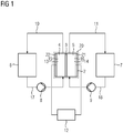
- FIG. 1 shows a rechargeable redox flow battery 1.
- the rechargeable redox flow battery 1 comprises a redox flow unit 20.
- the redox flow unit 20 comprises a membrane 3, the membrane 3 having a first chamber 4 and a second Separates chamber 5.
- a cathode 15 is arranged in the first chamber 4.
- An anode 16 is arranged in the second chamber 5.
- the cathode 15 and the anode 16 are connected to a power grid via an electrical power connection 12.
- the rechargeable redox flow battery 1 further comprises a first tank 6, which is connected to the first chamber 4 with the cathode 15 by means of a first pump 8 via a first line.
- the first chamber 4 is in turn connected to the first tank 6 via a third line 10.
- the rechargeable redox flow battery 1 comprises a second tank 7 which is connected via a second pump 9 to the second chamber 5 to the anode 16 via a second line 18.
- the second chamber 5 is in turn connected to the second tank 7 by a
- FIG. 2 shows a first embodiment of a redox flow unit 20 with a first chamber 4, in which a porous graphite electrode, in this case the cathode 15, is arranged.
- the redox flow unit 20 further comprises a second chamber 5, in which a planar anode 16 with elongate elevations 27 is arranged.
- the cathode 15 borders directly on a current collector 22.
- the anode 16 also borders on a current collector 21.
- the graphite electrode 15 touches both the current collector 22 and the membrane 3.
- the anode completely touches the collector 21 and the membrane partially by means of the elevations 27.
- Flow channels 26 are formed between the elevations 27.
- the flow channel has a first width 36 and a second width 37.
- the second width 37 increases in this exemplary embodiment.
- the first width 36 is typically in a range from 0.5 mm to 20 mm, preferably from 1 mm to 10 mm.
- the second width 37 of the flow channel 24 is typically in a range from 0.05 mm to 20 mm, particularly preferably from 0.1 mm to 10 mm.
- the first width 36 is constant. Alternatively, it is also possible for the first and second widths 36, 37 to decrease along the flow channel 26 or to be constant for widths.
- the cross sections can in particular be selected as a function of a desired target residence time of the anolyte at the anode.
- the flow channels 26 are delimited on three sides by the anode 16 and on one side by the membrane 3.
- the planar anode 16 comprises a first material 25, the first material in this exemplary embodiment comprising at least 10% lead.
- the anode 16 itself is not porous.
- the anode 16 can comprise at least 10% bismuth.
- the anode can further comprise carbon and carbon. Alloys, especially those made of lead or bismuth, can also be used.
- An electrolyte as catholyte 23 is fed into the first chamber 4.
- the catholyte 23 flows through the pore structure of the graphite electrode 15.
- An electrolyte as an anolyte is fed into the second chamber 5.
- the anolyte flows in a meandering fashion through the flow channels 26 of the anode 16.
- the residence time of the anolyte at the anode is reduced compared to porous electrodes, the reduction-oxidation pairs typically used in redox flow cells, in particular based on polyoxometalate, can also be of short length Residence times are effectively reduced or oxidized.
- the residence time can be changed using the shape of the flow channels 26 so that the dwell time can be adjusted depending on the reduction-oxidation pair used.
- the low overvoltage potential compared to hydrogen advantageously reduces hydrogen production at the anode compared to porous electrodes.
- Figure 3 shows a second embodiment of a redox flow unit 20 with a porous graphite electrode in the first chamber 4 and a planar anode 16 with elevations 27 in the second chamber 5.
- the anode only touches the current collector 21, but not the membrane 3.
- the anode 16 in this second exemplary embodiment comprises two materials which are arranged in layers one above the other.
- the base body of the anode 16 essentially comprises the second material 28 and is coated with a layer comprising the first material 25.
- the second material 28 comprises polymer fibers.
- the second material can also comprise carbon fibers.
- An electrolyte is supplied as a catholyte in the first chamber 4.
- the catholyte flows through the pore structure of the graphite electrode.
- An electrolyte as an anolyte is fed into the second chamber 5.
- the anolyte flows along the flow channel 26 and also penetrates into the depressions between the elevations 27.
- This arrangement is particularly suitable for reduction-oxidation pairs, which have a short residence time at the anode to ensure a sufficient degree of oxidation for storing the energy.
- Such a structure is particularly suitable if a polyoxometalate is used as the reduction-oxidation pair.
- Figure 4 shows a redox flow unit 20 according to a third embodiment.
- the first chamber 4 there is a planar one Cathode 30 with elevations 27 and flow channels 26 arranged.
- a planar anode 16 with elevations 27 is arranged in the second chamber 5.
- the elevations 27 differ in their shape.
- the cathode 30 has cuboid elevations, the anode 16 has pyramid elevations. In this example, the tips of the pyramid touch the membrane 3.
- Flow channels 26 thus form, through which the anolyte can flow.
- the catholyte also flows in a meandering manner over the cathode 30.
- the exemplary embodiments can be combined with one another.
- the anode in the first exemplary embodiment also comprises two layers. All of the above-mentioned designs of the anode can also be transferred to the cathode.
- a planar cathode 30 with elevations 27 in the first chamber 4 and a porous anode can be arranged in a redox flow unit 2.
- the elevations 27 on the electrode can have different shapes in all three exemplary embodiments. The different shapes are in the Figures 5 to 9 illustrated by the anode 16. However, they can also be transferred to the cathode 30.
- Figure 5 shows elevations 27 as they are arranged in the first and second exemplary embodiments for the anode 16 and in the third exemplary embodiment for the cathode 30.
- the elevations form a meandering river channel 26.
- FIG. 6 each shows flow channels 26, which are formed by cavities in cylindrical or cuboid elevations 27. These flow channels 26 have a very short residence time for the electrolyte at the electrode.
- the dwell time here is similar to a completely planar one, essentially smooth, surface of an electrode. Such an electrode is also conceivable, but not shown here.
- the anode 16 comprises in Figure 7 hemispherical elevations 31, in Figure 8 pyramidal elevations 34 and in Figure 9 cube-shaped surveys 35.
- the number of surveys can be different.
Landscapes
- Chemical & Material Sciences (AREA)
- Chemical Kinetics & Catalysis (AREA)
- Electrochemistry (AREA)
- General Chemical & Material Sciences (AREA)
- Engineering & Computer Science (AREA)
- Manufacturing & Machinery (AREA)
- Life Sciences & Earth Sciences (AREA)
- Sustainable Development (AREA)
- Sustainable Energy (AREA)
- Fuel Cell (AREA)
- Inert Electrodes (AREA)
Claims (11)
- Batterie (1) redox-flow rechargeable électriquement, comprenant une première chambre (4) et une deuxième chambre (5), la première chambre (4) étant séparée de la deuxième chambre (5) au moyen d'une membrane (3), la première chambre (4) entourant une cathode (30) et la deuxième chambre (5) entourant une anode (16), et dans laquelle une première surface plane de la cathode (30) et/ou une deuxième surface plane de l'anode (16) a des surélévations (27) pour augmenter la surface et ces surélévations (27) sont propres à former des canaux (26) d'écoulement d'un premier et/ou d'un deuxième électrolyte de la batterie (1) redox-flow, la cathode (30) et/ou l'anode (16) comprenant au moins un premier matériau (25), comprenant du plomb ou du bismuth, le premier matériau (25) comprenant du plomb ou du bismuth en une proportion en poids d'au moins 20%.
- Batterie (1) redox-flow suivant la revendication 1, dans laquelle les surélévations (27) ont un premier côté long et un deuxième côté (36) court.
- Batterie (1) redox-flow suivant l'une des revendications précédentes, dans laquelle les surélévations (27) sont disposées parallèlement ou sinueusement.
- Batterie (1) redox-flow suivant l'une des revendications précédentes, dans laquelle le premier matériau (25) comprend du plomb ou du bismuth en une proportion en poids d'au moins 40%.
- Batterie (1) redox-flow suivant l'une des revendications précédentes, dans laquelle la cathode (30) et/ou l'anode (16) touchent directement la membrane (3), au moins en partie.
- Batterie (1) redox-flow suivant l'une des revendications précédentes, dans laquelle la cathode (30) et/ou l'anode (16) comprennent un deuxième matériau (28) et dans laquelle le deuxième matériau (28) comprend des fibres de polymère ou des fibres de carbone.
- Batterie (1) redox-flow suivant la revendication 6, dans laquelle une proportion en poids du deuxième matériau est d'au moins 10%.
- Batterie (1) redox-flow suivant la revendication 7, dans laquelle le premier matériau (25) est disposé sous la forme d'une couche sur le deuxième matériau (28).
- Batterie (1) redox-flow suivant l'une des revendications précédentes, dans laquelle l'anode (16) et/ou la cathode (30) est une électrode boule ou une électrode barreau.
- Procédé pour faire fonctionner une batterie (1) redox-flow, comprenant les stades suivants :- on se procure une batterie (1) redox-flow, ayant une première chambre (4) et une deuxième chambre (5), la première chambre (4) étant séparée de la deuxième chambre (5) au moyen d'une membrane (3), la première chambre (4) entourant une cathode (30) et la deuxième chambre (5) entourant une anode (16), et dans laquelle une première surface plane de la cathode (30) et/ou une deuxième surface plane de l'anode (16) a des surélévations (27) pour augmenter la surface et ces surélévations (27) sont propres à former des canaux (26) d'écoulement d'un premier et/ou d'un deuxième électrolyte de la batterie (1) redox-flow, la cathode (30) et/ou l'anode (16) comprenant au moins un premier matériau (25), comprenant du plomb ou du bismuth, le premier matériau (25) comprenant du plomb ou du bismuth en une proportion en poids d'au moins 20%,- on envoie un premier électrolyte dans la première chambre (4) et on envoie un deuxième électrolyte dans la deuxième chambre (5),- on charge ou on décharge la batterie (1) redox-flow.
- Procédé suivant la revendication 10, dans lequel on utilise un polyoxométallate comme couple de réduction-oxydation dans l'électrolyte.
Priority Applications (8)
| Application Number | Priority Date | Filing Date | Title |
|---|---|---|---|
| EP17275122.4A EP3439093B1 (fr) | 2017-08-04 | 2017-08-04 | Batterie à flux redox et procédé de fonctionnement d'une batterie à flux redox |
| ES17275122T ES2781301T3 (es) | 2017-08-04 | 2017-08-04 | Batería de flujo redox y procedimiento para el funcionamiento de una batería de flujo redox |
| DK17275122.4T DK3439093T3 (da) | 2017-08-04 | 2017-08-04 | Redox-flow-batteri og fremgangsmåde til drift af et redox-flow-batteri |
| EP18748872.1A EP3625845A1 (fr) | 2017-08-04 | 2018-07-18 | Batterie redox et procédé pour faire fonctionner une batterie redox |
| US16/636,221 US11424471B2 (en) | 2017-08-04 | 2018-07-18 | Redox flow battery |
| PCT/EP2018/069538 WO2019025190A1 (fr) | 2017-08-04 | 2018-07-18 | Batterie redox et procédé pour faire fonctionner une batterie redox |
| JP2019565811A JP2020523731A (ja) | 2017-08-04 | 2018-07-18 | レドックスフロー電池およびレドックスフロー電池を作動するための方法 |
| CN201880050194.2A CN110998946A (zh) | 2017-08-04 | 2018-07-18 | 氧化还原液流电池和运行氧化还原液流电池的方法 |
Applications Claiming Priority (1)
| Application Number | Priority Date | Filing Date | Title |
|---|---|---|---|
| EP17275122.4A EP3439093B1 (fr) | 2017-08-04 | 2017-08-04 | Batterie à flux redox et procédé de fonctionnement d'une batterie à flux redox |
Publications (2)
| Publication Number | Publication Date |
|---|---|
| EP3439093A1 EP3439093A1 (fr) | 2019-02-06 |
| EP3439093B1 true EP3439093B1 (fr) | 2020-01-15 |
Family
ID=59558345
Family Applications (2)
| Application Number | Title | Priority Date | Filing Date |
|---|---|---|---|
| EP17275122.4A Active EP3439093B1 (fr) | 2017-08-04 | 2017-08-04 | Batterie à flux redox et procédé de fonctionnement d'une batterie à flux redox |
| EP18748872.1A Withdrawn EP3625845A1 (fr) | 2017-08-04 | 2018-07-18 | Batterie redox et procédé pour faire fonctionner une batterie redox |
Family Applications After (1)
| Application Number | Title | Priority Date | Filing Date |
|---|---|---|---|
| EP18748872.1A Withdrawn EP3625845A1 (fr) | 2017-08-04 | 2018-07-18 | Batterie redox et procédé pour faire fonctionner une batterie redox |
Country Status (7)
| Country | Link |
|---|---|
| US (1) | US11424471B2 (fr) |
| EP (2) | EP3439093B1 (fr) |
| JP (1) | JP2020523731A (fr) |
| CN (1) | CN110998946A (fr) |
| DK (1) | DK3439093T3 (fr) |
| ES (1) | ES2781301T3 (fr) |
| WO (1) | WO2019025190A1 (fr) |
Families Citing this family (6)
| Publication number | Priority date | Publication date | Assignee | Title |
|---|---|---|---|---|
| EP3439093B1 (fr) | 2017-08-04 | 2020-01-15 | Siemens Aktiengesellschaft | Batterie à flux redox et procédé de fonctionnement d'une batterie à flux redox |
| AU2021265103A1 (en) | 2020-04-29 | 2023-01-19 | Bristol-Myers Squibb Company | Miniaturized dystrophins having spectrin fusion domains and uses thereof |
| US11677093B2 (en) * | 2020-05-15 | 2023-06-13 | Ess Tech, Inc. | Electrode assembly for a redox flow battery |
| EP4181239A1 (fr) | 2021-11-15 | 2023-05-17 | Litricity GmbH | Cellule électrochimique |
| US11881605B2 (en) * | 2022-02-25 | 2024-01-23 | The Chinese University Of Hong Kong | Low-temperature aqueous redox flow battery |
| WO2023200652A1 (fr) * | 2022-04-15 | 2023-10-19 | Washington University | Batterie redox découplée par électrode |
Family Cites Families (15)
| Publication number | Priority date | Publication date | Assignee | Title |
|---|---|---|---|---|
| JPH02195650A (ja) * | 1989-01-23 | 1990-08-02 | Sumitomo Electric Ind Ltd | レドックスフロー電池用電極 |
| JP3844103B2 (ja) * | 1998-06-10 | 2006-11-08 | 東洋紡績株式会社 | 液流通型電解槽用溝付き電極材及びその製造方法 |
| JP4823446B2 (ja) * | 2001-08-22 | 2011-11-24 | 株式会社フジコー | 凹凸面フェルト材 |
| GB0718577D0 (en) * | 2007-09-24 | 2007-10-31 | Acal Energy Ltd | Fuel cells |
| WO2011126908A2 (fr) * | 2010-03-30 | 2011-10-13 | Applied Materials, Inc. | Batterie à circulation haute performance |
| US8486567B2 (en) * | 2010-05-10 | 2013-07-16 | Gas Technology Institute | Batteries, fuel cells, and other electrochemical devices |
| JP6034788B2 (ja) * | 2010-09-08 | 2016-11-30 | プリマス パワー コーポレイション | フロー電池用金属電極組立品 |
| JP2013004351A (ja) * | 2011-06-17 | 2013-01-07 | Jx Metals Trading Co Ltd | レドックスフロー電池用電極材及びそれを備えたレドックスフロー電池 |
| JP6018450B2 (ja) * | 2012-07-31 | 2016-11-02 | 東邦テナックス株式会社 | 炭素繊維フェルト、その製造方法、及び電極 |
| US20140050947A1 (en) * | 2012-08-07 | 2014-02-20 | Recapping, Inc. | Hybrid Electrochemical Energy Storage Devices |
| US9685651B2 (en) * | 2012-09-05 | 2017-06-20 | Ess Tech, Inc. | Internally manifolded flow cell for an all-iron hybrid flow battery |
| CN104241661B (zh) * | 2014-09-23 | 2017-04-19 | 中国科学院金属研究所 | 一种全钒液流电池用复合电极的制备方法 |
| DE102015212234A1 (de) * | 2015-06-30 | 2017-01-26 | Sgl Carbon Se | Verfahren zur Herstellung von Kohlenstofffilzelektroden für Redox Flow Batterien |
| JP2017091617A (ja) * | 2015-11-02 | 2017-05-25 | 旭化成株式会社 | カーボンフェルト、二次電池、及び、カーボンフェルトの製造方法 |
| EP3439093B1 (fr) | 2017-08-04 | 2020-01-15 | Siemens Aktiengesellschaft | Batterie à flux redox et procédé de fonctionnement d'une batterie à flux redox |
-
2017
- 2017-08-04 EP EP17275122.4A patent/EP3439093B1/fr active Active
- 2017-08-04 DK DK17275122.4T patent/DK3439093T3/da active
- 2017-08-04 ES ES17275122T patent/ES2781301T3/es active Active
-
2018
- 2018-07-18 WO PCT/EP2018/069538 patent/WO2019025190A1/fr not_active Ceased
- 2018-07-18 CN CN201880050194.2A patent/CN110998946A/zh active Pending
- 2018-07-18 JP JP2019565811A patent/JP2020523731A/ja active Pending
- 2018-07-18 US US16/636,221 patent/US11424471B2/en active Active
- 2018-07-18 EP EP18748872.1A patent/EP3625845A1/fr not_active Withdrawn
Non-Patent Citations (1)
| Title |
|---|
| None * |
Also Published As
| Publication number | Publication date |
|---|---|
| EP3439093A1 (fr) | 2019-02-06 |
| ES2781301T3 (es) | 2020-09-01 |
| JP2020523731A (ja) | 2020-08-06 |
| US11424471B2 (en) | 2022-08-23 |
| EP3625845A1 (fr) | 2020-03-25 |
| CN110998946A (zh) | 2020-04-10 |
| US20200168938A1 (en) | 2020-05-28 |
| WO2019025190A1 (fr) | 2019-02-07 |
| DK3439093T3 (da) | 2020-04-14 |
Similar Documents
| Publication | Publication Date | Title |
|---|---|---|
| EP3439093B1 (fr) | Batterie à flux redox et procédé de fonctionnement d'une batterie à flux redox | |
| DE102012017306A1 (de) | Elektrochemische Zelle vom Durchflusstyp | |
| DE102018112638A1 (de) | Phosphonium-basierte ionische Flüssigkeiten für Lithium-Metall-basierte Batterien | |
| EP3631881A1 (fr) | Accumulateur d'énergie | |
| WO2019166324A1 (fr) | Batterie à flux redox pourvue d'au moins une cellule et d'un élément à électrode ainsi que procédé de fabrication d'une structure conductrice d'un élément à électrode d'une batterie à flux redox | |
| DE102015224578A1 (de) | Bipolarer stromkollektor für eine lithium-luft-batterie, verfahren zum herstellen derselben und lithium-luft-batterie mit demselben | |
| EP3456866A1 (fr) | Procédé de fabrication d'un interconnecteur, interconnecteur et son utilisation | |
| WO2019020351A1 (fr) | Batterie redox et procédé de fonctionnement d'une batterie redox | |
| EP4499901A2 (fr) | Structure de distribution pour cellules électrochimiques, électrolyseur et installation power-to-x | |
| DE102014104601A1 (de) | Elektrochemische Zelle, insbesondere für eine Redox-Flow-Batterie, sowie Verfahren zur Herstellung | |
| EP2888779B1 (fr) | Électrode pour cellule galvanique | |
| EP4150137B1 (fr) | Empilement de cellules, procédé de production d'un empilement de cellules, et pile à combustible ou cellule d'électrolyse comprenant un empilement de cellules | |
| WO2018077908A1 (fr) | Procédé de fabrication d'un élément lithium-ion et d'une batterie lithium-ion et batterie lithium-ion | |
| DE102023130583B3 (de) | Elektrische Zelle und Verfahren | |
| DE102011084019A1 (de) | Batterie mit faser- oder fadenförmiger Elektrode | |
| DE102024208666A1 (de) | Natrium-Ionen-Akkumulator und Verfahren zur Fertigung eines Natrium-Ionen-Akkumulators | |
| DE102020101890B4 (de) | Bismut-Ionen-Akkumulator und Verfahren zu dessen Herstellung | |
| DE102024208665A1 (de) | Natrium-Ionen-Akkumulator und Verfahren zur Fertigung eines Natrium-Ionen-Akkumulators | |
| DE102018222728A1 (de) | Elektrode für chemische Reaktoren, insbesondere für Redox-Flow-Batterien und Redox-Flow-Batterie mit einer solchen Elektrode | |
| DE102024208667A1 (de) | Natrium-Ionen-Akkumulator und Verfahren zur Fertigung eines Natrium-Ionen-Akkumulators | |
| EP1675205B1 (fr) | Accumulateur alcalin | |
| DE102022202213A1 (de) | Verfahren zum Herstellen einer Elektrode, Elektrode, Lithiumionenzelle | |
| DE102021001212A1 (de) | Kollektorfolie für eine Anode und/oder eine Kathode einer Lithium-Ionen-Batterie, sowie Lithium-Ionen-Batterie | |
| WO2022007989A1 (fr) | Cellule d'électrolyse et appareil d'électrolyse | |
| DE102005061908A1 (de) | Brennstoffzelleneinheit |
Legal Events
| Date | Code | Title | Description |
|---|---|---|---|
| PUAI | Public reference made under article 153(3) epc to a published international application that has entered the european phase |
Free format text: ORIGINAL CODE: 0009012 |
|
| STAA | Information on the status of an ep patent application or granted ep patent |
Free format text: STATUS: THE APPLICATION HAS BEEN PUBLISHED |
|
| AK | Designated contracting states |
Kind code of ref document: A1 Designated state(s): AL AT BE BG CH CY CZ DE DK EE ES FI FR GB GR HR HU IE IS IT LI LT LU LV MC MK MT NL NO PL PT RO RS SE SI SK SM TR |
|
| AX | Request for extension of the european patent |
Extension state: BA ME |
|
| STAA | Information on the status of an ep patent application or granted ep patent |
Free format text: STATUS: REQUEST FOR EXAMINATION WAS MADE |
|
| 17P | Request for examination filed |
Effective date: 20190719 |
|
| RBV | Designated contracting states (corrected) |
Designated state(s): AL AT BE BG CH CY CZ DE DK EE ES FI FR GB GR HR HU IE IS IT LI LT LU LV MC MK MT NL NO PL PT RO RS SE SI SK SM TR |
|
| GRAP | Despatch of communication of intention to grant a patent |
Free format text: ORIGINAL CODE: EPIDOSNIGR1 |
|
| STAA | Information on the status of an ep patent application or granted ep patent |
Free format text: STATUS: GRANT OF PATENT IS INTENDED |
|
| INTG | Intention to grant announced |
Effective date: 20190911 |
|
| GRAS | Grant fee paid |
Free format text: ORIGINAL CODE: EPIDOSNIGR3 |
|
| GRAA | (expected) grant |
Free format text: ORIGINAL CODE: 0009210 |
|
| STAA | Information on the status of an ep patent application or granted ep patent |
Free format text: STATUS: THE PATENT HAS BEEN GRANTED |
|
| AK | Designated contracting states |
Kind code of ref document: B1 Designated state(s): AL AT BE BG CH CY CZ DE DK EE ES FI FR GB GR HR HU IE IS IT LI LT LU LV MC MK MT NL NO PL PT RO RS SE SI SK SM TR |
|
| REG | Reference to a national code |
Ref country code: CH Ref legal event code: EP Ref country code: GB Ref legal event code: FG4D Free format text: NOT ENGLISH |
|
| REG | Reference to a national code |
Ref country code: IE Ref legal event code: FG4D Free format text: LANGUAGE OF EP DOCUMENT: GERMAN |
|
| REG | Reference to a national code |
Ref country code: DE Ref legal event code: R096 Ref document number: 502017003512 Country of ref document: DE |
|
| REG | Reference to a national code |
Ref country code: AT Ref legal event code: REF Ref document number: 1225966 Country of ref document: AT Kind code of ref document: T Effective date: 20200215 |
|
| REG | Reference to a national code |
Ref country code: DK Ref legal event code: T3 Effective date: 20200407 |
|
| REG | Reference to a national code |
Ref country code: NL Ref legal event code: MP Effective date: 20200115 |
|
| REG | Reference to a national code |
Ref country code: LT Ref legal event code: MG4D |
|
| PG25 | Lapsed in a contracting state [announced via postgrant information from national office to epo] |
Ref country code: NL Free format text: LAPSE BECAUSE OF FAILURE TO SUBMIT A TRANSLATION OF THE DESCRIPTION OR TO PAY THE FEE WITHIN THE PRESCRIBED TIME-LIMIT Effective date: 20200115 Ref country code: NO Free format text: LAPSE BECAUSE OF FAILURE TO SUBMIT A TRANSLATION OF THE DESCRIPTION OR TO PAY THE FEE WITHIN THE PRESCRIBED TIME-LIMIT Effective date: 20200415 Ref country code: FI Free format text: LAPSE BECAUSE OF FAILURE TO SUBMIT A TRANSLATION OF THE DESCRIPTION OR TO PAY THE FEE WITHIN THE PRESCRIBED TIME-LIMIT Effective date: 20200115 Ref country code: RS Free format text: LAPSE BECAUSE OF FAILURE TO SUBMIT A TRANSLATION OF THE DESCRIPTION OR TO PAY THE FEE WITHIN THE PRESCRIBED TIME-LIMIT Effective date: 20200115 Ref country code: PT Free format text: LAPSE BECAUSE OF FAILURE TO SUBMIT A TRANSLATION OF THE DESCRIPTION OR TO PAY THE FEE WITHIN THE PRESCRIBED TIME-LIMIT Effective date: 20200607 |
|
| PG25 | Lapsed in a contracting state [announced via postgrant information from national office to epo] |
Ref country code: IS Free format text: LAPSE BECAUSE OF FAILURE TO SUBMIT A TRANSLATION OF THE DESCRIPTION OR TO PAY THE FEE WITHIN THE PRESCRIBED TIME-LIMIT Effective date: 20200515 Ref country code: SE Free format text: LAPSE BECAUSE OF FAILURE TO SUBMIT A TRANSLATION OF THE DESCRIPTION OR TO PAY THE FEE WITHIN THE PRESCRIBED TIME-LIMIT Effective date: 20200115 Ref country code: LV Free format text: LAPSE BECAUSE OF FAILURE TO SUBMIT A TRANSLATION OF THE DESCRIPTION OR TO PAY THE FEE WITHIN THE PRESCRIBED TIME-LIMIT Effective date: 20200115 Ref country code: HR Free format text: LAPSE BECAUSE OF FAILURE TO SUBMIT A TRANSLATION OF THE DESCRIPTION OR TO PAY THE FEE WITHIN THE PRESCRIBED TIME-LIMIT Effective date: 20200115 Ref country code: GR Free format text: LAPSE BECAUSE OF FAILURE TO SUBMIT A TRANSLATION OF THE DESCRIPTION OR TO PAY THE FEE WITHIN THE PRESCRIBED TIME-LIMIT Effective date: 20200416 Ref country code: BG Free format text: LAPSE BECAUSE OF FAILURE TO SUBMIT A TRANSLATION OF THE DESCRIPTION OR TO PAY THE FEE WITHIN THE PRESCRIBED TIME-LIMIT Effective date: 20200415 |
|
| REG | Reference to a national code |
Ref country code: ES Ref legal event code: FG2A Ref document number: 2781301 Country of ref document: ES Kind code of ref document: T3 Effective date: 20200901 |
|
| REG | Reference to a national code |
Ref country code: DE Ref legal event code: R097 Ref document number: 502017003512 Country of ref document: DE |
|
| PG25 | Lapsed in a contracting state [announced via postgrant information from national office to epo] |
Ref country code: EE Free format text: LAPSE BECAUSE OF FAILURE TO SUBMIT A TRANSLATION OF THE DESCRIPTION OR TO PAY THE FEE WITHIN THE PRESCRIBED TIME-LIMIT Effective date: 20200115 Ref country code: SM Free format text: LAPSE BECAUSE OF FAILURE TO SUBMIT A TRANSLATION OF THE DESCRIPTION OR TO PAY THE FEE WITHIN THE PRESCRIBED TIME-LIMIT Effective date: 20200115 Ref country code: SK Free format text: LAPSE BECAUSE OF FAILURE TO SUBMIT A TRANSLATION OF THE DESCRIPTION OR TO PAY THE FEE WITHIN THE PRESCRIBED TIME-LIMIT Effective date: 20200115 Ref country code: RO Free format text: LAPSE BECAUSE OF FAILURE TO SUBMIT A TRANSLATION OF THE DESCRIPTION OR TO PAY THE FEE WITHIN THE PRESCRIBED TIME-LIMIT Effective date: 20200115 Ref country code: CZ Free format text: LAPSE BECAUSE OF FAILURE TO SUBMIT A TRANSLATION OF THE DESCRIPTION OR TO PAY THE FEE WITHIN THE PRESCRIBED TIME-LIMIT Effective date: 20200115 Ref country code: LT Free format text: LAPSE BECAUSE OF FAILURE TO SUBMIT A TRANSLATION OF THE DESCRIPTION OR TO PAY THE FEE WITHIN THE PRESCRIBED TIME-LIMIT Effective date: 20200115 |
|
| PGFP | Annual fee paid to national office [announced via postgrant information from national office to epo] |
Ref country code: DK Payment date: 20200821 Year of fee payment: 4 |
|
| PLBE | No opposition filed within time limit |
Free format text: ORIGINAL CODE: 0009261 |
|
| STAA | Information on the status of an ep patent application or granted ep patent |
Free format text: STATUS: NO OPPOSITION FILED WITHIN TIME LIMIT |
|
| 26N | No opposition filed |
Effective date: 20201016 |
|
| PG25 | Lapsed in a contracting state [announced via postgrant information from national office to epo] |
Ref country code: IT Free format text: LAPSE BECAUSE OF FAILURE TO SUBMIT A TRANSLATION OF THE DESCRIPTION OR TO PAY THE FEE WITHIN THE PRESCRIBED TIME-LIMIT Effective date: 20200115 |
|
| PGFP | Annual fee paid to national office [announced via postgrant information from national office to epo] |
Ref country code: DE Payment date: 20201019 Year of fee payment: 4 |
|
| PG25 | Lapsed in a contracting state [announced via postgrant information from national office to epo] |
Ref country code: SI Free format text: LAPSE BECAUSE OF FAILURE TO SUBMIT A TRANSLATION OF THE DESCRIPTION OR TO PAY THE FEE WITHIN THE PRESCRIBED TIME-LIMIT Effective date: 20200115 Ref country code: PL Free format text: LAPSE BECAUSE OF FAILURE TO SUBMIT A TRANSLATION OF THE DESCRIPTION OR TO PAY THE FEE WITHIN THE PRESCRIBED TIME-LIMIT Effective date: 20200115 |
|
| PG25 | Lapsed in a contracting state [announced via postgrant information from national office to epo] |
Ref country code: MC Free format text: LAPSE BECAUSE OF FAILURE TO SUBMIT A TRANSLATION OF THE DESCRIPTION OR TO PAY THE FEE WITHIN THE PRESCRIBED TIME-LIMIT Effective date: 20200115 |
|
| REG | Reference to a national code |
Ref country code: CH Ref legal event code: PL |
|
| PG25 | Lapsed in a contracting state [announced via postgrant information from national office to epo] |
Ref country code: CH Free format text: LAPSE BECAUSE OF NON-PAYMENT OF DUE FEES Effective date: 20200831 Ref country code: LU Free format text: LAPSE BECAUSE OF NON-PAYMENT OF DUE FEES Effective date: 20200804 Ref country code: LI Free format text: LAPSE BECAUSE OF NON-PAYMENT OF DUE FEES Effective date: 20200831 |
|
| REG | Reference to a national code |
Ref country code: BE Ref legal event code: MM Effective date: 20200831 |
|
| PG25 | Lapsed in a contracting state [announced via postgrant information from national office to epo] |
Ref country code: FR Free format text: LAPSE BECAUSE OF NON-PAYMENT OF DUE FEES Effective date: 20200831 |
|
| PG25 | Lapsed in a contracting state [announced via postgrant information from national office to epo] |
Ref country code: BE Free format text: LAPSE BECAUSE OF NON-PAYMENT OF DUE FEES Effective date: 20200831 Ref country code: IE Free format text: LAPSE BECAUSE OF NON-PAYMENT OF DUE FEES Effective date: 20200804 |
|
| REG | Reference to a national code |
Ref country code: DE Ref legal event code: R119 Ref document number: 502017003512 Country of ref document: DE |
|
| REG | Reference to a national code |
Ref country code: DK Ref legal event code: EBP Effective date: 20210831 |
|
| GBPC | Gb: european patent ceased through non-payment of renewal fee |
Effective date: 20210804 |
|
| PG25 | Lapsed in a contracting state [announced via postgrant information from national office to epo] |
Ref country code: TR Free format text: LAPSE BECAUSE OF FAILURE TO SUBMIT A TRANSLATION OF THE DESCRIPTION OR TO PAY THE FEE WITHIN THE PRESCRIBED TIME-LIMIT Effective date: 20200115 Ref country code: MT Free format text: LAPSE BECAUSE OF FAILURE TO SUBMIT A TRANSLATION OF THE DESCRIPTION OR TO PAY THE FEE WITHIN THE PRESCRIBED TIME-LIMIT Effective date: 20200115 Ref country code: CY Free format text: LAPSE BECAUSE OF FAILURE TO SUBMIT A TRANSLATION OF THE DESCRIPTION OR TO PAY THE FEE WITHIN THE PRESCRIBED TIME-LIMIT Effective date: 20200115 |
|
| PG25 | Lapsed in a contracting state [announced via postgrant information from national office to epo] |
Ref country code: MK Free format text: LAPSE BECAUSE OF FAILURE TO SUBMIT A TRANSLATION OF THE DESCRIPTION OR TO PAY THE FEE WITHIN THE PRESCRIBED TIME-LIMIT Effective date: 20200115 Ref country code: AL Free format text: LAPSE BECAUSE OF FAILURE TO SUBMIT A TRANSLATION OF THE DESCRIPTION OR TO PAY THE FEE WITHIN THE PRESCRIBED TIME-LIMIT Effective date: 20200115 |
|
| PG25 | Lapsed in a contracting state [announced via postgrant information from national office to epo] |
Ref country code: GB Free format text: LAPSE BECAUSE OF NON-PAYMENT OF DUE FEES Effective date: 20210804 Ref country code: DK Free format text: LAPSE BECAUSE OF NON-PAYMENT OF DUE FEES Effective date: 20210831 Ref country code: DE Free format text: LAPSE BECAUSE OF NON-PAYMENT OF DUE FEES Effective date: 20220301 |
|
| REG | Reference to a national code |
Ref country code: ES Ref legal event code: PC2A Owner name: LITRICITY GMBH Effective date: 20230614 |
|
| REG | Reference to a national code |
Ref country code: AT Ref legal event code: MM01 Ref document number: 1225966 Country of ref document: AT Kind code of ref document: T Effective date: 20220804 |
|
| PG25 | Lapsed in a contracting state [announced via postgrant information from national office to epo] |
Ref country code: AT Free format text: LAPSE BECAUSE OF NON-PAYMENT OF DUE FEES Effective date: 20220804 |
|
| PGFP | Annual fee paid to national office [announced via postgrant information from national office to epo] |
Ref country code: ES Payment date: 20240918 Year of fee payment: 8 |