EP3439111B1 - Optimiertes crimpen von zwei elektrischen anschlüssen - Google Patents
Optimiertes crimpen von zwei elektrischen anschlüssen Download PDFInfo
- Publication number
- EP3439111B1 EP3439111B1 EP18186842.3A EP18186842A EP3439111B1 EP 3439111 B1 EP3439111 B1 EP 3439111B1 EP 18186842 A EP18186842 A EP 18186842A EP 3439111 B1 EP3439111 B1 EP 3439111B1
- Authority
- EP
- European Patent Office
- Prior art keywords
- connector
- zones
- assembly
- connectors
- main axis
- Prior art date
- Legal status (The legal status is an assumption and is not a legal conclusion. Google has not performed a legal analysis and makes no representation as to the accuracy of the status listed.)
- Active
Links
Images
Classifications
-
- H—ELECTRICITY
- H01—ELECTRIC ELEMENTS
- H01R—ELECTRICALLY-CONDUCTIVE CONNECTIONS; STRUCTURAL ASSOCIATIONS OF A PLURALITY OF MUTUALLY-INSULATED ELECTRICAL CONNECTING ELEMENTS; COUPLING DEVICES; CURRENT COLLECTORS
- H01R43/00—Apparatus or processes specially adapted for manufacturing, assembling, maintaining, or repairing of line connectors or current collectors or for joining electric conductors
- H01R43/04—Apparatus or processes specially adapted for manufacturing, assembling, maintaining, or repairing of line connectors or current collectors or for joining electric conductors for forming connections by deformation, e.g. crimping tool
- H01R43/048—Crimping apparatus or processes
- H01R43/0488—Crimping apparatus or processes with crimp height adjusting means
-
- H—ELECTRICITY
- H01—ELECTRIC ELEMENTS
- H01R—ELECTRICALLY-CONDUCTIVE CONNECTIONS; STRUCTURAL ASSOCIATIONS OF A PLURALITY OF MUTUALLY-INSULATED ELECTRICAL CONNECTING ELEMENTS; COUPLING DEVICES; CURRENT COLLECTORS
- H01R4/00—Electrically-conductive connections between two or more conductive members in direct contact, i.e. touching one another; Means for effecting or maintaining such contact; Electrically-conductive connections having two or more spaced connecting locations for conductors and using contact members penetrating insulation
- H01R4/10—Electrically-conductive connections between two or more conductive members in direct contact, i.e. touching one another; Means for effecting or maintaining such contact; Electrically-conductive connections having two or more spaced connecting locations for conductors and using contact members penetrating insulation effected solely by twisting, wrapping, bending, crimping, or other permanent deformation
- H01R4/18—Electrically-conductive connections between two or more conductive members in direct contact, i.e. touching one another; Means for effecting or maintaining such contact; Electrically-conductive connections having two or more spaced connecting locations for conductors and using contact members penetrating insulation effected solely by twisting, wrapping, bending, crimping, or other permanent deformation by crimping
- H01R4/188—Electrically-conductive connections between two or more conductive members in direct contact, i.e. touching one another; Means for effecting or maintaining such contact; Electrically-conductive connections having two or more spaced connecting locations for conductors and using contact members penetrating insulation effected solely by twisting, wrapping, bending, crimping, or other permanent deformation by crimping having an uneven wire-receiving surface to improve the contact
Definitions
- the invention relates to electrical connectors. More particularly, the invention relates to the crimping of electrical connectors.
- a known method is to crimp a first of these connectors into the second. This consists in inserting the first electrical connector inside the second and in squeezing a section of this assembly in which the second connector covers the first connector. This compression, which must be sufficient to deform the section, makes it possible to ensure the electrical contact between the two connectors and therefore the flow of electricity from one to the other of the connectors.
- the first connector can be an electrical wire comprising several strands and the second can be a wiring lug.
- the strands are generally made of copper, but it may be desirable to make them of aluminum for certain applications because of its low density (about three times lower than that of copper).
- the first is to create an efficient electrical connection between the two connectors.
- the second consists in creating a solid mechanical connection, in particular in tension, between the two connectors.
- a third aspect crimping can be provided in order to improve the aesthetics of the whole.
- US2015364833A1 , EP1658662A1 , US2015364835A1 and EP1503454A1 each disclose the crimping of connectors between them.
- An object of the invention is to overcome these drawbacks by simplifying the crimping of the first connector in the second connector.
- a crimping method according to claim 1 is provided.
- the relative position of the two areas of the walls of the mold is fixed and known.
- the reproducibility of the crimping is thus improved in that it makes it possible to guarantee the adjacency of the two pressed zones of the assembly.
- each wall has a general shape of “W”.
- the walls are thus simple to produce and allow effective pressurization.
- the walls form cavities of different areas in the zones in sections perpendicular to the main axis.
- the first wall of the mold forming a fixed die, a punch carrying the second wall is pressed in the direction of the first wall.
- the crimping is thus done in a simple way, by pressing the punch in the direction of the die.
- the crimping can easily be configured with the punch.
- the shape of the pressed areas of the assembly can be changed during crimping. Flexibility is therefore provided in the crimping process.
- the second connector has ridges on an internal surface.
- the ridges of the second connector make it possible to create a plurality of pressure points on the first connector, which allows the second connector to grip the first connector.
- the tensile strength of the assembly is thus improved, which contributes to improving the mechanical properties of the crimping.
- the first electrical connector is made of aluminum.
- the pressure points created by the second connector make it possible to break an insulating layer of alumina which forms on the surface of the first connector by oxidation. This constraint is therefore overcome, which makes it possible to improve the electrical properties of the assembly.
- a set of first and second electrical connectors as defined in claim 4 is also provided according to the invention.
- the second connector has ridges on an internal surface.
- the ridges of the second connector make it possible to create a plurality of pressure points on the first connector which make it possible to break the layer of alumina which forms on the surface of the strands if they are made in aluminum. This constraint is therefore overcome, which makes it possible to improve the electrical properties of the assembly.
- the plurality of pressure points allow the second connector to grip the first connector.
- the tensile strength of the assembly is thus improved, which contributes to improving the mechanical properties of the crimping.
- the ridges make it possible to increase the contact surface between the first and second connectors, which improves the electrical conduction between them.
- the ridges extend helically over the inner surface of the second connector.
- the ridges form an angle of between 10 and 80 ° with a main axis of the assembly.
- the second connector is made from a copper alloy.
- the second connector is thus made of a material having a hardness greater than that of aluminum, which facilitates the breaking of the layer of alumina in the case where the first connector is made of aluminum.
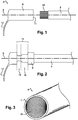
- the set 2 includes first 4 and second 6 electrical connectors.
- the first connector 4 is intended to be crimped in the second connector 6.
- the first and second connectors 4, 6 are here generally cylindrical in shape and have main axes coinciding with a main axis 8 of the assembly 2.
- the first connector 4 is formed by an electric wire comprising one or more strands 10 made of an electrically conductive material.
- the strands 10 are made of aluminum, but it can very well be provided that they are made of any other conductive material, for example any metal.
- the second connector 6 has at one axial end an opening 11, the dimensions of which allow the insertion of the first connector 4.
- the second connector 6 is here formed by a wiring lug and comprises a tab 12 allowing its subsequent fixing.
- the second connector 6 is made of a material having a hardness greater than that of the material in which the strands 10 of the first connector 4 are made.
- the strands 10 being made of aluminum, one can for example choose to make the second connector 6 in a relatively inexpensive copper alloy. However, you can choose another material for the second connector 6.
- the second connector 6 has striations 20 on an internal surface. These stripes 20 extend helically on the internal surface of the second connector 6, here at an angle approximately equal to 45 ° with the axis 8. In general, the stripes ridges 20 form an angle between 10 and 80 ° with the axis 8.
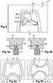
- the mold 21 used to crimp the first connector 4 in the second connector 6.
- the mold 21 comprises a die 22 and a punch 24 respectively forming first and second parts of the mold 21.
- the die 22 has a wall having different shapes in two zones 22a, 22b which follow one another along the axis 8.
- the punch 24 has a wall having different shapes in two zones 24a, 24b which follow each other. along axis 8.
- zone 22a is located opposite zone 24a and zone 22b is located opposite zone 24b.
- each wall has a general shape of “W”.
- the walls form cavities of different areas in the zones in sections perpendicular to the axis 8.
- the first connector 4 is inserted into the second connector 6. This is permitted by the dimensions of the connectors 4, 6 as stated in the above.
- the assembly 2 is placed in the die 22 so that a section 14 of the assembly 2 in which the two connectors 4, 6 are radially superimposed can be pressed into the mold 21.
- the punch 24 is pressed in the direction of the die 22 so as to compress the section 14.
- the mold 21 then occupies the configuration illustrated in figures 5a and 5b .
- the figure 5a is a section comprising areas 22a and 24a
- the figure 5b is a section comprising Figures 22b and 24b.
- the assembly 2 resulting from this crimping process is illustrated in figure 2 .
- the section 14 is formed by zones 16 and 18 in which the assembly 2 is compressed. Zone 16 of section 14 has been compressed by zones 22a and 24a of mold 21, and zone 18 of section 14 has been compressed by zones 22b and 24b of mold 21.
- a double crimping has thus been produced having two different functions. : an electrical crimping and a mechanical crimping.
- Zone 16 namely the least compressed zone, is located closer to the opening 11 of the second connector 6 than the zone 18. Otherwise, the zone 18 would create a zone of mechanical weakness of the assembly 2. And there is also the risk of cutting the first connector 4 during crimping. In other words, the arrangement of zones 16 and 18 is chosen to maximize the mechanical and electrical performance of assembly 2.
- the figures 6a and 6b illustrate more precisely the state of the first and second connectors 4, 6 after crimping.
- the figure 6a is a section including zone 16, and the figure 6b is a section comprising zone 18. It is observed in particular that the strands 10 and the second connector 6 are compressed and take the form of the walls of the mold 21.
- the second connector 6 has two opposite outer faces 6A, 6B, each outer face 6A, 6B having the shape of a respective wall of the mold 21.
- each outer face 6A, 6B has different shapes in the two zones. 16, 18.
- Each external face 6A, 6B has here, in section perpendicular to the main axis 8 and in each of the zones 16, 18, a general shape of “W”.
- the assembly formed by the first and second connectors 4, 6 has different areas in the zones 16, 18, in section perpendicular to the main axis 8.
- the ridges 20 of the second connector 6 penetrate into the strands 10. This is permitted by the fact that the second connector 6 is made in a material having a hardness greater than that of the material in which the strands 10 are made. As a result, the striations 20 can break the alumina layer forming at the second connector 6 / strands 10 interface. And the penetration of the striations 20 improves the resistance to tearing of the assembly 2.
Landscapes
- Engineering & Computer Science (AREA)
- Manufacturing & Machinery (AREA)
- Connections Effected By Soldering, Adhesion, Or Permanent Deformation (AREA)
- Manufacturing Of Electrical Connectors (AREA)
- Multi-Conductor Connections (AREA)
- Coupling Device And Connection With Printed Circuit (AREA)
Claims (10)
- Verfahren zum Crimpen eines ersten Anschlusses (4) in einem zweiten Anschluss (6), wobei die beiden Anschlüsse (4, 6) zwischen einer ersten und zweiten Wand einer Form (21) gepresst werden, wobei diese Wände jeweils unterschiedliche Formen in Zonen aufweisen, die sich entlang einer Hauptachse (8) der Anschlüsse (4, 6) anschließen, wobei im Querschnitt senkrecht zur Hauptachse (8) und in jeder der Zonen jede Wand eine allgemeine "W"-Form hat und wobei der zweite Anschluss (6) auf einer inneren Oberfläche Rillen (20) aufweist.
- Verfahren nach vorangehendem Anspruch, wobei, sobald die Form (21) geschlossen ist, die Wände Hohlräume unterschiedlicher Bereiche in den Zonen der zur Hauptachse (8) senkrechten Querschnitte bilden.
- Verfahren nach einem der vorangehenden Ansprüche, wobei, wobei die erste Wand der Form (21) eine feste Matrize (22) bildet, ein die zweite Wand tragender Stempel (24) in Richtung der ersten Wand gedrückt wird.
- Montage (2) aus einem ersten und einem zweiten elektrischen Anschluss (4, 6), wobei der erste Anschluss (4) im zweiten Anschluss (6) gecrimt ist, wobei die Montage (2) mindestens zwei Zonen umfasst, die sich entlang einer Hauptachse (8) des Anschlusses (4, 6) anschließen, in die die Anschlüsse (4, 6) gepresst sind, wobei die Anschlüsse (4, 6) in den zwei Zonen in zur Hauptachse (8) senkrechten Querschnitten unterschiedliche Formen aufweisen, wobei die Formen durch Pressen der zwei Anschlüsse (4, 6) zwischen der ersten und zweiten Wand einer Form (21) erhalten werden, wobei jede dieser Wände unterschiedliche Formen in den zwei Zonen aufweist und wobei jede Wand im Querschnitt senkrecht zur Hauptachse (8) und in jeder der Zonen eine allgemeine "W"-Form hat und wobei der zweite Anschluss (6) auf einer inneren Oberfläche Rillen (20) aufweist.
- Montage nach Anspruch 4, wobei der zweite Anschluss zwei gegenüberliegende äußere Flächen (6a, 6B) aufweist, wobei jede äußere Fläche (6A, 6B) in den zwei Zonen (16, 18) unterschiedliche Formen aufweist.
- Montage nach Anspruch 5, wobei jede Fläche im Querschnitt senkrecht zur Hauptachse (8) und in jeder der Zonen (16, 18) eine allgemeine "W"-Form hat.
- Montage nach einem der Ansprüche 4 bis 6, die in den Zonen (16, 18) in Querschnitten senkrecht zur Hauptachse (8) unterschiedliche Bereiche besitzt.
- Montage (2) nach Anspruch 7, wobei sich die Rillen (20) schraubenförmig auf der inneren Oberfläche des zweiten Anschlusses (6) erstrecken.
- Montage (2) nach einem der Ansprüche 4 bis 8, wobei die Rillen (20) mit einer Hauptachse (8) der Montage (2) einen Winkel zwischen 10 und 80° bilden.
- Montage (2) nach einem der Ansprüche 4 bis 9, wobei der zweite Anschluss (6) aus einer kupferhaltigen Legierung hergestellt ist.
Priority Applications (1)
| Application Number | Priority Date | Filing Date | Title |
|---|---|---|---|
| SI201830597T SI3439111T1 (sl) | 2017-08-01 | 2018-08-01 | Optimizirano stiskanje dveh električnih konektorjev |
Applications Claiming Priority (1)
| Application Number | Priority Date | Filing Date | Title |
|---|---|---|---|
| FR1757371A FR3069965B1 (fr) | 2017-08-01 | 2017-08-01 | Sertissage optimise de deux connecteurs electriques |
Publications (2)
| Publication Number | Publication Date |
|---|---|
| EP3439111A1 EP3439111A1 (de) | 2019-02-06 |
| EP3439111B1 true EP3439111B1 (de) | 2021-12-22 |
Family
ID=60765736
Family Applications (1)
| Application Number | Title | Priority Date | Filing Date |
|---|---|---|---|
| EP18186842.3A Active EP3439111B1 (de) | 2017-08-01 | 2018-08-01 | Optimiertes crimpen von zwei elektrischen anschlüssen |
Country Status (4)
| Country | Link |
|---|---|
| EP (1) | EP3439111B1 (de) |
| ES (1) | ES2904898T3 (de) |
| FR (1) | FR3069965B1 (de) |
| SI (1) | SI3439111T1 (de) |
Families Citing this family (1)
| Publication number | Priority date | Publication date | Assignee | Title |
|---|---|---|---|---|
| DE102020103866A1 (de) * | 2020-02-14 | 2021-08-19 | Phoenix Contact E-Mobility Gmbh | Kontaktelementbaugruppe für ein Steckverbinderteil |
Citations (2)
| Publication number | Priority date | Publication date | Assignee | Title |
|---|---|---|---|---|
| EP1503454B1 (de) * | 2003-07-30 | 2015-08-05 | Furukawa Electric Co. Ltd. | Krimanschlussklemme für Aluminium Kabel und Herstellungsverfahren |
| EP1658662B1 (de) * | 2003-08-19 | 2016-07-27 | Delphi International Operations Luxembourg S.à r.l. | Krimpverfahren eines elektrischen kontakts und durch dieses verfahren hergestellten kontakt |
Family Cites Families (3)
| Publication number | Priority date | Publication date | Assignee | Title |
|---|---|---|---|---|
| US6676458B2 (en) * | 2000-09-21 | 2004-01-13 | Yazaki Corporation | Structure and method for connecting terminal and electric wire |
| CN105009386B (zh) * | 2013-02-23 | 2017-11-28 | 古河电气工业株式会社 | 连接结构体的制造方法、连接结构体、线束、压接部件和压接装置 |
| WO2014129092A1 (ja) * | 2013-02-23 | 2014-08-28 | 古河電気工業株式会社 | 接続構造体、端子圧着部材、ワイヤハーネス、コネクタ、接続構造体の圧着方法及びその圧着する圧着装置 |
-
2017
- 2017-08-01 FR FR1757371A patent/FR3069965B1/fr not_active Expired - Fee Related
-
2018
- 2018-08-01 EP EP18186842.3A patent/EP3439111B1/de active Active
- 2018-08-01 SI SI201830597T patent/SI3439111T1/sl unknown
- 2018-08-01 ES ES18186842T patent/ES2904898T3/es active Active
Patent Citations (2)
| Publication number | Priority date | Publication date | Assignee | Title |
|---|---|---|---|---|
| EP1503454B1 (de) * | 2003-07-30 | 2015-08-05 | Furukawa Electric Co. Ltd. | Krimanschlussklemme für Aluminium Kabel und Herstellungsverfahren |
| EP1658662B1 (de) * | 2003-08-19 | 2016-07-27 | Delphi International Operations Luxembourg S.à r.l. | Krimpverfahren eines elektrischen kontakts und durch dieses verfahren hergestellten kontakt |
Also Published As
| Publication number | Publication date |
|---|---|
| FR3069965A1 (fr) | 2019-02-08 |
| EP3439111A1 (de) | 2019-02-06 |
| FR3069965B1 (fr) | 2021-02-12 |
| ES2904898T3 (es) | 2022-04-06 |
| SI3439111T1 (sl) | 2022-04-29 |
Similar Documents
| Publication | Publication Date | Title |
|---|---|---|
| EP0310487B1 (de) | Elektrische Kontaktklemme der Käfigart | |
| FR2960102B1 (fr) | Contacts electriques utilisant des ressorts helicoidaux inclines et boitiers estampes ainsi que leurs procedes de fabrication | |
| CA2106297C (fr) | Procede de raccordement d'un cable electrique comportant une ame en metal leger sur un element d'extremite normalise, et piece de raccordement pour la mise en oeuvre de ce procede | |
| EP2706616B1 (de) | Verfahren zum Zusammenbau einer Verbindungsvorrichtung auf einem blanken Endstück eines Elektrokabels, und Einheit, die eine solche fest auf einem Kabelendstück montierte Vorrichtung umfasst | |
| JP5634788B2 (ja) | 圧着端子 | |
| EP3252874B1 (de) | Muffe für buchsenkontakt, stecker der eine solche muffe verwendet, und ihr herstellungsverfahren | |
| EP3266068B1 (de) | Verfahren zum crimpen eines elektrischen kontakts auf ein kabel und werkzeug zur durchführung des verfahrens | |
| EP2477278B1 (de) | Anschlussmuffe für elektrischen Anschluss, und Zusammenbauverfahren | |
| FR2844104A1 (fr) | Borne de contact munie d'une lame de contact elastique | |
| FR2673490A1 (fr) | Procede de fabrication de contact electrique par decoupe et pliage. | |
| WO2008034957A1 (fr) | Contact electrique hermaphrodite | |
| EP3439111A1 (de) | Optimiertes crimpen von zwei elektrischen anschlüssen | |
| FR2515885A1 (fr) | Procede de production d'une electrode composite pour bougie d'allumage et cette electrode | |
| FR2557741A1 (fr) | Contact electrique a faible force d'insertion et son procede de realisation | |
| FR2579836A1 (fr) | Embout pour conducteur electrique et son procede de fabrication | |
| FR2916089A1 (fr) | Connecteur pour cable coaxial a ame cylindrique creuse | |
| FR2819348A1 (fr) | Connexion autodenudante a fente convergente | |
| EP2335318B1 (de) | Durch autogenes nieten erhaltene elektrische/mechanische baugruppe | |
| EP1588460A1 (de) | Ellbogenförmiger elektrischer stecker | |
| FR3000619A1 (fr) | Organe de raccordement de conducteurs sur une borne unique | |
| WO2018203105A1 (fr) | Contact electrique femelle et son procede de fabrication | |
| EP0011031A1 (de) | Verbinder zur Verbindung ohne Abisolieren von elektrischen Leitungsdrähten und Werkzeuge zum Anquetschen für einen solchen Verbinder | |
| FR2596588A1 (fr) | Contact femelle a douille fendue pour connecteur electrique | |
| FR3038778A1 (fr) | Procede de fabrication d'un contact a insertion en force dans un logement, outil pour la mise en œuvre de ce procede et contact a insertion en force | |
| FR3116667A1 (fr) | Contact de puissance à portion de sertissage améliorée |
Legal Events
| Date | Code | Title | Description |
|---|---|---|---|
| PUAI | Public reference made under article 153(3) epc to a published international application that has entered the european phase |
Free format text: ORIGINAL CODE: 0009012 |
|
| STAA | Information on the status of an ep patent application or granted ep patent |
Free format text: STATUS: THE APPLICATION HAS BEEN PUBLISHED |
|
| AK | Designated contracting states |
Kind code of ref document: A1 Designated state(s): AL AT BE BG CH CY CZ DE DK EE ES FI FR GB GR HR HU IE IS IT LI LT LU LV MC MK MT NL NO PL PT RO RS SE SI SK SM TR |
|
| AX | Request for extension of the european patent |
Extension state: BA ME |
|
| STAA | Information on the status of an ep patent application or granted ep patent |
Free format text: STATUS: REQUEST FOR EXAMINATION WAS MADE |
|
| 17P | Request for examination filed |
Effective date: 20190718 |
|
| RBV | Designated contracting states (corrected) |
Designated state(s): AL AT BE BG CH CY CZ DE DK EE ES FI FR GB GR HR HU IE IS IT LI LT LU LV MC MK MT NL NO PL PT RO RS SE SI SK SM TR |
|
| STAA | Information on the status of an ep patent application or granted ep patent |
Free format text: STATUS: EXAMINATION IS IN PROGRESS |
|
| 17Q | First examination report despatched |
Effective date: 20200313 |
|
| GRAP | Despatch of communication of intention to grant a patent |
Free format text: ORIGINAL CODE: EPIDOSNIGR1 |
|
| STAA | Information on the status of an ep patent application or granted ep patent |
Free format text: STATUS: GRANT OF PATENT IS INTENDED |
|
| INTG | Intention to grant announced |
Effective date: 20210916 |
|
| GRAS | Grant fee paid |
Free format text: ORIGINAL CODE: EPIDOSNIGR3 |
|
| GRAA | (expected) grant |
Free format text: ORIGINAL CODE: 0009210 |
|
| STAA | Information on the status of an ep patent application or granted ep patent |
Free format text: STATUS: THE PATENT HAS BEEN GRANTED |
|
| AK | Designated contracting states |
Kind code of ref document: B1 Designated state(s): AL AT BE BG CH CY CZ DE DK EE ES FI FR GB GR HR HU IE IS IT LI LT LU LV MC MK MT NL NO PL PT RO RS SE SI SK SM TR |
|
| REG | Reference to a national code |
Ref country code: GB Ref legal event code: FG4D Free format text: NOT ENGLISH |
|
| REG | Reference to a national code |
Ref country code: CH Ref legal event code: EP |
|
| REG | Reference to a national code |
Ref country code: DE Ref legal event code: R096 Ref document number: 602018028433 Country of ref document: DE |
|
| REG | Reference to a national code |
Ref country code: AT Ref legal event code: REF Ref document number: 1457674 Country of ref document: AT Kind code of ref document: T Effective date: 20220115 |
|
| REG | Reference to a national code |
Ref country code: IE Ref legal event code: FG4D Free format text: LANGUAGE OF EP DOCUMENT: FRENCH |
|
| REG | Reference to a national code |
Ref country code: ES Ref legal event code: FG2A Ref document number: 2904898 Country of ref document: ES Kind code of ref document: T3 Effective date: 20220406 |
|
| REG | Reference to a national code |
Ref country code: LT Ref legal event code: MG9D |
|
| REG | Reference to a national code |
Ref country code: SK Ref legal event code: T3 Ref document number: E 39080 Country of ref document: SK |
|
| PG25 | Lapsed in a contracting state [announced via postgrant information from national office to epo] |
Ref country code: RS Free format text: LAPSE BECAUSE OF FAILURE TO SUBMIT A TRANSLATION OF THE DESCRIPTION OR TO PAY THE FEE WITHIN THE PRESCRIBED TIME-LIMIT Effective date: 20211222 Ref country code: LT Free format text: LAPSE BECAUSE OF FAILURE TO SUBMIT A TRANSLATION OF THE DESCRIPTION OR TO PAY THE FEE WITHIN THE PRESCRIBED TIME-LIMIT Effective date: 20211222 Ref country code: FI Free format text: LAPSE BECAUSE OF FAILURE TO SUBMIT A TRANSLATION OF THE DESCRIPTION OR TO PAY THE FEE WITHIN THE PRESCRIBED TIME-LIMIT Effective date: 20211222 Ref country code: BG Free format text: LAPSE BECAUSE OF FAILURE TO SUBMIT A TRANSLATION OF THE DESCRIPTION OR TO PAY THE FEE WITHIN THE PRESCRIBED TIME-LIMIT Effective date: 20220322 |
|
| REG | Reference to a national code |
Ref country code: NL Ref legal event code: MP Effective date: 20211222 |
|
| REG | Reference to a national code |
Ref country code: AT Ref legal event code: MK05 Ref document number: 1457674 Country of ref document: AT Kind code of ref document: T Effective date: 20211222 |
|
| PG25 | Lapsed in a contracting state [announced via postgrant information from national office to epo] |
Ref country code: SE Free format text: LAPSE BECAUSE OF FAILURE TO SUBMIT A TRANSLATION OF THE DESCRIPTION OR TO PAY THE FEE WITHIN THE PRESCRIBED TIME-LIMIT Effective date: 20211222 Ref country code: NO Free format text: LAPSE BECAUSE OF FAILURE TO SUBMIT A TRANSLATION OF THE DESCRIPTION OR TO PAY THE FEE WITHIN THE PRESCRIBED TIME-LIMIT Effective date: 20220322 Ref country code: LV Free format text: LAPSE BECAUSE OF FAILURE TO SUBMIT A TRANSLATION OF THE DESCRIPTION OR TO PAY THE FEE WITHIN THE PRESCRIBED TIME-LIMIT Effective date: 20211222 Ref country code: HR Free format text: LAPSE BECAUSE OF FAILURE TO SUBMIT A TRANSLATION OF THE DESCRIPTION OR TO PAY THE FEE WITHIN THE PRESCRIBED TIME-LIMIT Effective date: 20211222 Ref country code: GR Free format text: LAPSE BECAUSE OF FAILURE TO SUBMIT A TRANSLATION OF THE DESCRIPTION OR TO PAY THE FEE WITHIN THE PRESCRIBED TIME-LIMIT Effective date: 20220323 |
|
| PG25 | Lapsed in a contracting state [announced via postgrant information from national office to epo] |
Ref country code: NL Free format text: LAPSE BECAUSE OF FAILURE TO SUBMIT A TRANSLATION OF THE DESCRIPTION OR TO PAY THE FEE WITHIN THE PRESCRIBED TIME-LIMIT Effective date: 20211222 |
|
| PG25 | Lapsed in a contracting state [announced via postgrant information from national office to epo] |
Ref country code: SM Free format text: LAPSE BECAUSE OF FAILURE TO SUBMIT A TRANSLATION OF THE DESCRIPTION OR TO PAY THE FEE WITHIN THE PRESCRIBED TIME-LIMIT Effective date: 20211222 Ref country code: RO Free format text: LAPSE BECAUSE OF FAILURE TO SUBMIT A TRANSLATION OF THE DESCRIPTION OR TO PAY THE FEE WITHIN THE PRESCRIBED TIME-LIMIT Effective date: 20211222 Ref country code: PT Free format text: LAPSE BECAUSE OF FAILURE TO SUBMIT A TRANSLATION OF THE DESCRIPTION OR TO PAY THE FEE WITHIN THE PRESCRIBED TIME-LIMIT Effective date: 20220422 Ref country code: EE Free format text: LAPSE BECAUSE OF FAILURE TO SUBMIT A TRANSLATION OF THE DESCRIPTION OR TO PAY THE FEE WITHIN THE PRESCRIBED TIME-LIMIT Effective date: 20211222 Ref country code: CZ Free format text: LAPSE BECAUSE OF FAILURE TO SUBMIT A TRANSLATION OF THE DESCRIPTION OR TO PAY THE FEE WITHIN THE PRESCRIBED TIME-LIMIT Effective date: 20211222 |
|
| PG25 | Lapsed in a contracting state [announced via postgrant information from national office to epo] |
Ref country code: PL Free format text: LAPSE BECAUSE OF FAILURE TO SUBMIT A TRANSLATION OF THE DESCRIPTION OR TO PAY THE FEE WITHIN THE PRESCRIBED TIME-LIMIT Effective date: 20211222 Ref country code: AT Free format text: LAPSE BECAUSE OF FAILURE TO SUBMIT A TRANSLATION OF THE DESCRIPTION OR TO PAY THE FEE WITHIN THE PRESCRIBED TIME-LIMIT Effective date: 20211222 |
|
| REG | Reference to a national code |
Ref country code: DE Ref legal event code: R097 Ref document number: 602018028433 Country of ref document: DE |
|
| PG25 | Lapsed in a contracting state [announced via postgrant information from national office to epo] |
Ref country code: IS Free format text: LAPSE BECAUSE OF FAILURE TO SUBMIT A TRANSLATION OF THE DESCRIPTION OR TO PAY THE FEE WITHIN THE PRESCRIBED TIME-LIMIT Effective date: 20220422 |
|
| PLBE | No opposition filed within time limit |
Free format text: ORIGINAL CODE: 0009261 |
|
| STAA | Information on the status of an ep patent application or granted ep patent |
Free format text: STATUS: NO OPPOSITION FILED WITHIN TIME LIMIT |
|
| PG25 | Lapsed in a contracting state [announced via postgrant information from national office to epo] |
Ref country code: DK Free format text: LAPSE BECAUSE OF FAILURE TO SUBMIT A TRANSLATION OF THE DESCRIPTION OR TO PAY THE FEE WITHIN THE PRESCRIBED TIME-LIMIT Effective date: 20211222 Ref country code: AL Free format text: LAPSE BECAUSE OF FAILURE TO SUBMIT A TRANSLATION OF THE DESCRIPTION OR TO PAY THE FEE WITHIN THE PRESCRIBED TIME-LIMIT Effective date: 20211222 |
|
| 26N | No opposition filed |
Effective date: 20220923 |
|
| PG25 | Lapsed in a contracting state [announced via postgrant information from national office to epo] |
Ref country code: MC Free format text: LAPSE BECAUSE OF FAILURE TO SUBMIT A TRANSLATION OF THE DESCRIPTION OR TO PAY THE FEE WITHIN THE PRESCRIBED TIME-LIMIT Effective date: 20211222 |
|
| REG | Reference to a national code |
Ref country code: CH Ref legal event code: PL |
|
| GBPC | Gb: european patent ceased through non-payment of renewal fee |
Effective date: 20220801 |
|
| PG25 | Lapsed in a contracting state [announced via postgrant information from national office to epo] |
Ref country code: LU Free format text: LAPSE BECAUSE OF NON-PAYMENT OF DUE FEES Effective date: 20220801 Ref country code: LI Free format text: LAPSE BECAUSE OF NON-PAYMENT OF DUE FEES Effective date: 20220831 Ref country code: CH Free format text: LAPSE BECAUSE OF NON-PAYMENT OF DUE FEES Effective date: 20220831 |
|
| REG | Reference to a national code |
Ref country code: BE Ref legal event code: MM Effective date: 20220831 |
|
| PG25 | Lapsed in a contracting state [announced via postgrant information from national office to epo] |
Ref country code: IE Free format text: LAPSE BECAUSE OF NON-PAYMENT OF DUE FEES Effective date: 20220801 |
|
| PG25 | Lapsed in a contracting state [announced via postgrant information from national office to epo] |
Ref country code: BE Free format text: LAPSE BECAUSE OF NON-PAYMENT OF DUE FEES Effective date: 20220831 |
|
| PG25 | Lapsed in a contracting state [announced via postgrant information from national office to epo] |
Ref country code: GB Free format text: LAPSE BECAUSE OF NON-PAYMENT OF DUE FEES Effective date: 20220801 |
|
| PG25 | Lapsed in a contracting state [announced via postgrant information from national office to epo] |
Ref country code: HU Free format text: LAPSE BECAUSE OF FAILURE TO SUBMIT A TRANSLATION OF THE DESCRIPTION OR TO PAY THE FEE WITHIN THE PRESCRIBED TIME-LIMIT; INVALID AB INITIO Effective date: 20180801 |
|
| PG25 | Lapsed in a contracting state [announced via postgrant information from national office to epo] |
Ref country code: MK Free format text: LAPSE BECAUSE OF FAILURE TO SUBMIT A TRANSLATION OF THE DESCRIPTION OR TO PAY THE FEE WITHIN THE PRESCRIBED TIME-LIMIT Effective date: 20211222 Ref country code: CY Free format text: LAPSE BECAUSE OF FAILURE TO SUBMIT A TRANSLATION OF THE DESCRIPTION OR TO PAY THE FEE WITHIN THE PRESCRIBED TIME-LIMIT Effective date: 20211222 |
|
| PG25 | Lapsed in a contracting state [announced via postgrant information from national office to epo] |
Ref country code: MT Free format text: LAPSE BECAUSE OF FAILURE TO SUBMIT A TRANSLATION OF THE DESCRIPTION OR TO PAY THE FEE WITHIN THE PRESCRIBED TIME-LIMIT Effective date: 20211222 |
|
| PGFP | Annual fee paid to national office [announced via postgrant information from national office to epo] |
Ref country code: ES Payment date: 20250908 Year of fee payment: 8 |
|
| PGFP | Annual fee paid to national office [announced via postgrant information from national office to epo] |
Ref country code: DE Payment date: 20250812 Year of fee payment: 8 |
|
| PGFP | Annual fee paid to national office [announced via postgrant information from national office to epo] |
Ref country code: TR Payment date: 20250731 Year of fee payment: 8 Ref country code: IT Payment date: 20250808 Year of fee payment: 8 |
|
| PGFP | Annual fee paid to national office [announced via postgrant information from national office to epo] |
Ref country code: FR Payment date: 20250710 Year of fee payment: 8 |
|
| PGFP | Annual fee paid to national office [announced via postgrant information from national office to epo] |
Ref country code: SK Payment date: 20250722 Year of fee payment: 8 |
|
| PGFP | Annual fee paid to national office [announced via postgrant information from national office to epo] |
Ref country code: SI Payment date: 20250721 Year of fee payment: 8 |