EP3439940B1 - Procédé de calcul de la vitesse d'avancement d'un véhicule ferroviaire - Google Patents
Procédé de calcul de la vitesse d'avancement d'un véhicule ferroviaire Download PDFInfo
- Publication number
- EP3439940B1 EP3439940B1 EP17724628.7A EP17724628A EP3439940B1 EP 3439940 B1 EP3439940 B1 EP 3439940B1 EP 17724628 A EP17724628 A EP 17724628A EP 3439940 B1 EP3439940 B1 EP 3439940B1
- Authority
- EP
- European Patent Office
- Prior art keywords
- axle
- adhesion
- speed
- wheels
- value
- Prior art date
- Legal status (The legal status is an assumption and is not a legal conclusion. Google has not performed a legal analysis and makes no representation as to the accuracy of the status listed.)
- Active
Links
Images




Classifications
-
- B—PERFORMING OPERATIONS; TRANSPORTING
- B60—VEHICLES IN GENERAL
- B60L—PROPULSION OF ELECTRICALLY-PROPELLED VEHICLES; SUPPLYING ELECTRIC POWER FOR AUXILIARY EQUIPMENT OF ELECTRICALLY-PROPELLED VEHICLES; ELECTRODYNAMIC BRAKE SYSTEMS FOR VEHICLES IN GENERAL; MAGNETIC SUSPENSION OR LEVITATION FOR VEHICLES; MONITORING OPERATING VARIABLES OF ELECTRICALLY-PROPELLED VEHICLES; ELECTRIC SAFETY DEVICES FOR ELECTRICALLY-PROPELLED VEHICLES
- B60L3/00—Electric devices on electrically-propelled vehicles for safety purposes; Monitoring operating variables, e.g. speed, deceleration or energy consumption
- B60L3/10—Indicating wheel slip ; Correction of wheel slip
- B60L3/106—Indicating wheel slip ; Correction of wheel slip for maintaining or recovering the adhesion of the drive wheels
- B60L3/108—Indicating wheel slip ; Correction of wheel slip for maintaining or recovering the adhesion of the drive wheels whilst braking, i.e. ABS
-
- B—PERFORMING OPERATIONS; TRANSPORTING
- B60—VEHICLES IN GENERAL
- B60L—PROPULSION OF ELECTRICALLY-PROPELLED VEHICLES; SUPPLYING ELECTRIC POWER FOR AUXILIARY EQUIPMENT OF ELECTRICALLY-PROPELLED VEHICLES; ELECTRODYNAMIC BRAKE SYSTEMS FOR VEHICLES IN GENERAL; MAGNETIC SUSPENSION OR LEVITATION FOR VEHICLES; MONITORING OPERATING VARIABLES OF ELECTRICALLY-PROPELLED VEHICLES; ELECTRIC SAFETY DEVICES FOR ELECTRICALLY-PROPELLED VEHICLES
- B60L3/00—Electric devices on electrically-propelled vehicles for safety purposes; Monitoring operating variables, e.g. speed, deceleration or energy consumption
- B60L3/10—Indicating wheel slip ; Correction of wheel slip
-
- B—PERFORMING OPERATIONS; TRANSPORTING
- B60—VEHICLES IN GENERAL
- B60L—PROPULSION OF ELECTRICALLY-PROPELLED VEHICLES; SUPPLYING ELECTRIC POWER FOR AUXILIARY EQUIPMENT OF ELECTRICALLY-PROPELLED VEHICLES; ELECTRODYNAMIC BRAKE SYSTEMS FOR VEHICLES IN GENERAL; MAGNETIC SUSPENSION OR LEVITATION FOR VEHICLES; MONITORING OPERATING VARIABLES OF ELECTRICALLY-PROPELLED VEHICLES; ELECTRIC SAFETY DEVICES FOR ELECTRICALLY-PROPELLED VEHICLES
- B60L3/00—Electric devices on electrically-propelled vehicles for safety purposes; Monitoring operating variables, e.g. speed, deceleration or energy consumption
- B60L3/10—Indicating wheel slip ; Correction of wheel slip
- B60L3/104—Indicating wheel slip ; Correction of wheel slip by indirect measurement of vehicle speed
-
- B—PERFORMING OPERATIONS; TRANSPORTING
- B61—RAILWAYS
- B61L—GUIDING RAILWAY TRAFFIC; ENSURING THE SAFETY OF RAILWAY TRAFFIC
- B61L15/00—Indicators provided on the vehicle or train for signalling purposes
- B61L15/0058—On-board optimisation of vehicle or vehicle train operation
-
- B—PERFORMING OPERATIONS; TRANSPORTING
- B61—RAILWAYS
- B61L—GUIDING RAILWAY TRAFFIC; ENSURING THE SAFETY OF RAILWAY TRAFFIC
- B61L25/00—Recording or indicating positions or identities of vehicles or trains or setting of track apparatus
- B61L25/02—Indicating or recording positions or identities of vehicles or trains
- B61L25/021—Measuring and recording of train speed
-
- Y—GENERAL TAGGING OF NEW TECHNOLOGICAL DEVELOPMENTS; GENERAL TAGGING OF CROSS-SECTIONAL TECHNOLOGIES SPANNING OVER SEVERAL SECTIONS OF THE IPC; TECHNICAL SUBJECTS COVERED BY FORMER USPC CROSS-REFERENCE ART COLLECTIONS [XRACs] AND DIGESTS
- Y02—TECHNOLOGIES OR APPLICATIONS FOR MITIGATION OR ADAPTATION AGAINST CLIMATE CHANGE
- Y02T—CLIMATE CHANGE MITIGATION TECHNOLOGIES RELATED TO TRANSPORTATION
- Y02T10/00—Road transport of goods or passengers
- Y02T10/60—Other road transportation technologies with climate change mitigation effect
- Y02T10/72—Electric energy management in electromobility
Definitions
- the present invention relates to a process for improving the computation of the advance speed of a railway vehicle, when all the axles of the vehicle are in the slipping phase due to degraded conditions of adhesion on the rails.
- a known method for accurately determining the speed of a railway vehicle is to maintain a "dead" axle, not subjected to traction or braking torques, so that the measurement of its speed is the best reproduction of the actual speed of said vehicle.
- This solution is particularly effective in the case of particularly low adhesion between the wheels and the rail, when, during traction or braking, all the wheels may enter into a slipping condition and therefore not be in a position to provide correct information regarding the actual speed of the vehicle.
- a "dead" axle not subjected to traction or braking torques could continue to be a reliable indicator of the vehicle speed.
- Figure 9A of the accompanying drawings shows a composition with two independent cars
- figure 9B shows a composition with two cars secured through a Jacobs bogie: it is evident how the use of a "dead" axle reduces the traction and braking capacity by 12.5% in the first case and by 16.7% in the second case.
- EP 0218839 A2 discloses a method for calculating or estimating the speed of a railway vehicle, at least one axle of which has an associated control system of the adhesion of the wheels to the rails.
- An object of the present invention is therefore to propose a new method that allows one to fully recover the use of the "dead" axle for the purposes of traction and braking, even in the case of particularly reduced adhesion, thereby increasing the traction and braking capacity of the train, while permitting said axle to accurately track the speed of the train for a precise assessment of the advance speed.
- the description of the present invention refers to the specific case of braking implemented by means of an anti-slip system. Those skilled in the art may however easily deduce a way to implement the present invention through an independent system. Also, those skilled in the art may deduce the dual application, relating to the case of traction, to which the subsequent claims of the present application refer.
- Wheel slide control subsystems intended to intervene both when the vehicle is in the traction phase and when it is in the braking phase.
- These subsystems are known as anti-skid or anti-slide systems, or also WSP (Wheel Slide Protection) systems.
- FIG. 1 of the accompanying drawings A system for controlling the adhesion of the wheels, as an anti-skid function, according to the prior art, is schematically represented in figure 1 of the accompanying drawings, which refers to a vehicle with n controlled axles A1, A2, ..., An.
- the axles A1, A2, ..., An comprise a respective shaft S1, S2, ..., Sn and a respective wheelset W1, W2, ..., Wn integral in rotation to it.
- the WSP system of figure 1 comprises an electronic control unit ECU, typically based on microprocessor architecture, that receives tachometer signals relating to the angular speed of each axle A1, A2, ...An from sensors SS1, SS2, ... , SSn respectively associated to these axles.
- the electronic control unit ECU is also connected to the torque control apparatuses TC1, TC2, ..., TCn, each associated to a respective axle A1, A2, ..., An.
- the electronic control unit ECU is provided to operate a modulation of the torque applied to each axle according to a predetermined algorithm if, in the case of applying torque during traction or braking in a degraded adhesion condition, the wheels of one or more axles end up in a possible incipient skidding condition.
- Torque modulation is implemented in such a way as to prevent a total locking of the axles, possibly so as to bring each axle into a condition of controlled slipping with the intention of recovering adhesion and in any case for the entire duration of the degraded adhesion condition.
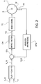
- FIG. 2 shows a block diagram illustrating an adhesion control/recovery system for a generic axle: the error or difference E(t) between the reference speed value V R (t) at which one wishes to slide the controlled axle A and the measured speed V M (t) detected by the associated sensor SS and conditioned by an acquisition and processing module APM is applied as an input signal to a control module CM, which outputs a drive signal Y(t) to the torque control apparatus TC associated with the axle A.
- a torque control apparatus may be made according to many variants known to persons skilled in the art.
- ⁇ Vv ⁇ Vr Vv with 0 ⁇ V r ⁇ V v and 0 ⁇ ⁇ ⁇ 1.
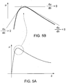
- curves 1, 2 and 3 qualitatively represent the trend of the adhesion according to the environmental conditions: curve 1 corresponds to an adhesion condition in dry contact conditions between the wheels and rails, curve 2 corresponds to an adhesion condition in the presence of moisture between the wheels and rails, and curve 3 represents an adhesion condition in the presence of viscous material between the wheels and rails, such as oil or rotten leaves (typical condition in the autumn period), or even rust mixed with moisture (typical condition in railway depots).
- viscous material between the wheels and rails such as oil or rotten leaves (typical condition in the autumn period), or even rust mixed with moisture (typical condition in railway depots).
- axles for example the one previously defined as the "dead" axle
- it is achieved the dual effect of using, for said axles, the maximum available adhesion and at the same time tracking the actual speed of the train, corresponding to ⁇ 0, with a maximum error of 2%.
- the method according to the present invention uses an adhesion observer to evaluate in real time the adhesion value ⁇ at the contact area between the wheels and rails for one or more axles during a skidding phase and, by processing these ⁇ values in real time, identifies continuously over time the ⁇ value to be assigned to a slip control system.
- a low-pass type filter may appropriately be provided, to remove or at least mitigate instantaneous and noise variations present outside of the frequency band useful for a correct observation of the adhesion values.
- FIG. 6 An embodiment of a system for implementing a method according to the present invention is illustrated in figure 6 .
- LMS Least Mean Square
- an adhesion observer 1201 receives input signals representative of the value of the speed co of the wheel of the controlled axle An that is to be maintained on the adhesion peak, together with an X vector containing the values of the magnitudes m(T j ), J, R and F m (T j ) previously described, for the estimation of the instantaneous value of adhesion ⁇ (T j ) relating to the controlled axle.
- An adder 1203 outputs an error signal e(T j ) as the difference between the desired value of said derivative (i.e. the value 0) and its instantaneous value computed by the module 1202, and such error is used to adapt the LMS algorithm implemented in a block 1204.
- the latter provides in output a torque request C(T j+1 ) for said axle, which is transmitted to a torque control module 1205 of a per se known type, having for example the architecture described in the previous aforementioned Italian patent application with reference to figure 3 .
- the module 1204 continuously corrects the output C(T j+1 ) in order to minimize or nullify the error e(T), i.e. in order to obtain a nullification of the aforementioned derivative, i.e. in order to bring and maintain said controlled axle to the adhesion peak value.
- said axle will always advance at a linear speed equal to that of the vehicle (less than a maximum error that can be estimated within 2%), even in degraded adhesion conditions, at the same time providing the maximum force value, in traction or braking, made possible by the available adhesion.
- FIG 7 A simplified implementation of the group of modules included in the dashed line block 1206 of figure 6 is illustrated in figure 7 , where the block 1204, which implements the LMS algorithm, is replaced with a simple integrator 805, the output of which, amplified with a gain K, generates the torque value C(T j+1 ) to be assigned to the adhesion control and recovery system 1205.
- the integrator 805 increases the torque value C(T j+1 )
- the integrator 805 decreases the torque value C(T j+1 )
- the integrator 805 keeps the torque value C(T j+1 ) stable.
- the gain K regulates the identification speed of the average adhesion peak value ⁇ and simultaneously ensures the stability of the closed loop system.
- FIG 8 A further simplified variant of embodiment of the dashed block 1206 of figure 6 is shown in figure 8 : the module 903 determines the sign of the derivative d ⁇ d ⁇ .
- the output of the block 903 being equal to +1 or -1 (positive and, respectively, negative sign), a subsequent integrator 805 performs simple unitary sums.
- the diagrams according to figures 7 and 8 perform a continuous tracking of the average adhesion peak ⁇ , continuously adapting to the change in adhesion conditions, similarly to what was achieved with the diagram according to figure 6 .
- the diagram according to figure 7 has features intermediate between those of the diagrams according to figures 6 and 8 .
- the two expressions (2), (3) provided above always allow a very reliable value of the vehicle's speed V V to be provided, even in very degraded adhesion conditions.
Landscapes
- Engineering & Computer Science (AREA)
- Mechanical Engineering (AREA)
- Life Sciences & Earth Sciences (AREA)
- Sustainable Development (AREA)
- Sustainable Energy (AREA)
- Power Engineering (AREA)
- Transportation (AREA)
- Regulating Braking Force (AREA)
- Electric Propulsion And Braking For Vehicles (AREA)
Claims (5)
- Procédé de calcul ou d'estimation de la vitesse d'un véhicule ferroviaire, dont au moins un essieu (A) comporte un système de contrôle associé (SS, CM, TC, APM) de l'adhérence des roues (W) aux rails ;
le procédé comprenant les étapes consistant à
générer des signaux de vitesse indiquant la vitesse angulaire (ω) des roues (W) dudit au moins un essieu (A) ;
estimer, en fonction de ladite vitesse angulaire (ω), la valeur de l'adhérence (µ) dans la zone de contact des roues (W) dudit essieu (A) et des rails, à l'aide d'un observateur d'adhérence (1201) et calculer la valeur du glissement de vitesse (δ) des roues (W) dudit essieu (A) commandé,
générer des signaux représentatifs de la dérivée
générer un signal de pilotage (C(Tj+1)) pour la commande par des moyens de commande de couple (1205) du couple appliqué aux roues (W) dudit essieu (A), au moyen d'une commande adaptative (1204) desdits signaux de dérivé

appliquer ledit signal de pilotage (C(Tj+1)) auxdits moyens de commande de couple (1205), puis calculer informatiquement la vitesse de véhicule en tant que vitesse d'avancée linéaire dudit au moins un essieu (A) commandé. - Procédé selon la revendication 1, dans lequel ledit signal de pilotage (C(Tj+1)) est généré au moyen d'un filtrage adaptatif de type LMS.
- Procédé selon la revendication 1, dans lequel ledit signal de pilotage (C(Tj+1)) est généré par l'intégration temporelle de la dérivée

- Procédé selon la revendication 1, dans lequel ledit signal de pilotage (C(Tj+1)) est généré par l'intégration temporelle du signe de la dérivée

- Procédé selon l'une quelconque des revendications précédentes, dans lequel ladite valeur de référence

Applications Claiming Priority (2)
| Application Number | Priority Date | Filing Date | Title |
|---|---|---|---|
| ITUA2016A002297A ITUA20162297A1 (it) | 2016-04-05 | 2016-04-05 | Procedimento per calcolare la velocità di avanzamento di un veicolo ferroviario. |
| PCT/IB2017/051902 WO2017175119A1 (fr) | 2016-04-05 | 2017-04-04 | Procédé de calcul de la vitesse d'avancement d'un véhicule ferroviaire |
Publications (2)
| Publication Number | Publication Date |
|---|---|
| EP3439940A1 EP3439940A1 (fr) | 2019-02-13 |
| EP3439940B1 true EP3439940B1 (fr) | 2020-11-18 |
Family
ID=56413762
Family Applications (1)
| Application Number | Title | Priority Date | Filing Date |
|---|---|---|---|
| EP17724628.7A Active EP3439940B1 (fr) | 2016-04-05 | 2017-04-04 | Procédé de calcul de la vitesse d'avancement d'un véhicule ferroviaire |
Country Status (9)
| Country | Link |
|---|---|
| US (1) | US20190111787A1 (fr) |
| EP (1) | EP3439940B1 (fr) |
| JP (1) | JP6983802B2 (fr) |
| CN (1) | CN109070916B (fr) |
| ES (1) | ES2854932T3 (fr) |
| HU (1) | HUE053336T2 (fr) |
| IT (1) | ITUA20162297A1 (fr) |
| RU (1) | RU2740353C2 (fr) |
| WO (1) | WO2017175119A1 (fr) |
Families Citing this family (6)
| Publication number | Priority date | Publication date | Assignee | Title |
|---|---|---|---|---|
| ITUA20162295A1 (it) * | 2016-04-05 | 2017-10-05 | Faiveley Transport Italia Spa | Procedimento per il controllo e l'eventuale recupero dell'aderenza delle ruote di assili controllati di un veicolo ferroviario. |
| US12311949B2 (en) | 2016-04-05 | 2025-05-27 | Faiveley Transport Italia S.P.A. | Vehicle control system |
| US10279823B2 (en) * | 2016-08-08 | 2019-05-07 | General Electric Company | System for controlling or monitoring a vehicle system along a route |
| EP3680123B1 (fr) * | 2019-01-09 | 2024-11-20 | ALSTOM Holdings | Procédé de commande d'un véhicule ferroviaire, organe de commande et véhicule ferroviaire |
| GB2591809B (en) * | 2020-02-10 | 2022-02-23 | Stored Energy Tech Limited | A method, apparatus, computer program and system for controlling a wheel of a rail mounted vehicle |
| DE102021210463A1 (de) * | 2021-09-21 | 2023-03-23 | Siemens Mobility GmbH | Verfahren und Einrichtung zum Messen eines für die Fahrt eines Schienenfahrzeugs relevanten Parameters |
Family Cites Families (14)
| Publication number | Priority date | Publication date | Assignee | Title |
|---|---|---|---|---|
| JPH07106007B2 (ja) * | 1985-01-21 | 1995-11-13 | 株式会社日立製作所 | 鉄道車両の粘着制御装置 |
| JPH088728B2 (ja) * | 1985-08-14 | 1996-01-29 | 株式会社日立製作所 | 電気車の再粘着制御装置 |
| DE4225683C2 (de) * | 1992-08-04 | 1998-07-23 | Rudolf Dr Ing Pfeiffer | Verfahren und Anordnung zur selbsttätigen Radschlupfregelung von Fahrzeugen mit drehmomentgeregeltem Antrieb |
| JP3826204B2 (ja) * | 1998-02-27 | 2006-09-27 | 東洋電機製造株式会社 | 電気車の接線力係数推定装置 |
| JP2000125406A (ja) * | 1998-10-15 | 2000-04-28 | Kiyoshi Oishi | 電気車制御装置 |
| US20050018987A1 (en) * | 2002-01-19 | 2005-01-27 | Tobias Ruf | Gas-filled optical fiber for wavelength calibration or measurement |
| JP3879924B2 (ja) * | 2002-12-25 | 2007-02-14 | 富士電機システムズ株式会社 | 駆動車両の制御装置 |
| EP1637863A1 (fr) * | 2004-09-20 | 2006-03-22 | PIRELLI PNEUMATICI S.p.A. | Procédé de calculer une caractéristique frottement-glissement d'un pneu |
| JP2008289237A (ja) * | 2007-05-16 | 2008-11-27 | Railway Technical Res Inst | 電動機制御装置及び再粘着制御方法 |
| JP4176144B1 (ja) * | 2007-09-18 | 2008-11-05 | 三菱電機株式会社 | 電気車用制御装置 |
| US8645011B2 (en) * | 2008-02-15 | 2014-02-04 | Schaffler Ip Pty Limited | Traction control system and method |
| JP5940290B2 (ja) * | 2011-12-09 | 2016-06-29 | 株式会社東芝 | 電気車制御装置 |
| JP6166211B2 (ja) * | 2014-03-31 | 2017-07-19 | 公益財団法人鉄道総合技術研究所 | 復帰制御方法、電動機制御装置及び機械ブレーキ制御装置 |
| CN104442450B (zh) * | 2014-12-16 | 2018-12-21 | 中国科学院深圳先进技术研究院 | 一种判断牵引状态下的车辆工作状态的方法和系统 |
-
2016
- 2016-04-05 IT ITUA2016A002297A patent/ITUA20162297A1/it unknown
-
2017
- 2017-04-04 WO PCT/IB2017/051902 patent/WO2017175119A1/fr not_active Ceased
- 2017-04-04 EP EP17724628.7A patent/EP3439940B1/fr active Active
- 2017-04-04 RU RU2018138795A patent/RU2740353C2/ru active
- 2017-04-04 ES ES17724628T patent/ES2854932T3/es active Active
- 2017-04-04 CN CN201780021035.5A patent/CN109070916B/zh active Active
- 2017-04-04 JP JP2018549898A patent/JP6983802B2/ja active Active
- 2017-04-04 HU HUE17724628A patent/HUE053336T2/hu unknown
- 2017-04-04 US US16/088,107 patent/US20190111787A1/en not_active Abandoned
Non-Patent Citations (1)
| Title |
|---|
| None * |
Also Published As
| Publication number | Publication date |
|---|---|
| EP3439940A1 (fr) | 2019-02-13 |
| RU2740353C2 (ru) | 2021-01-13 |
| HUE053336T2 (hu) | 2021-06-28 |
| ITUA20162297A1 (it) | 2017-10-05 |
| CN109070916A (zh) | 2018-12-21 |
| ES2854932T3 (es) | 2021-09-23 |
| CN109070916B (zh) | 2020-12-08 |
| RU2018138795A3 (fr) | 2020-07-02 |
| RU2018138795A (ru) | 2020-05-12 |
| JP6983802B2 (ja) | 2021-12-17 |
| WO2017175119A1 (fr) | 2017-10-12 |
| JP2019511190A (ja) | 2019-04-18 |
| US20190111787A1 (en) | 2019-04-18 |
Similar Documents
| Publication | Publication Date | Title |
|---|---|---|
| EP3439940B1 (fr) | Procédé de calcul de la vitesse d'avancement d'un véhicule ferroviaire | |
| EP3439928B1 (fr) | Procédé de commande et de récupération éventuelle de l'adhérence des roues d'un essieu commandé d'un véhicule ferroviaire | |
| US11834083B2 (en) | System and method for calculating advance speed of a vehicle | |
| RU2564461C2 (ru) | Способ управления снабженной противоюзным регулятором фрикционной тормозной системой рельсового транспортного средства | |
| EP0342789B1 (fr) | Méthode pour estimer la vitesse et l'accélération de référence pour commande d'entraînement et de freinage à antipatinage | |
| KR101493634B1 (ko) | 브레이크압 연산 장치, 브레이크 제어 시스템, 및 기록 매체 | |
| US5402345A (en) | Method for estimating speed of a braked vehicle | |
| JP2008539112A (ja) | スリップ調節器を用いたレール車両のための適応滑走保護 | |
| US11529982B2 (en) | Vehicle control system | |
| US12559070B2 (en) | Method for controlling a braking system of a vehicle and system thereof | |
| AU2020415919A1 (en) | Locomotive and weighted parameter adhesion control method therefor | |
| CN110799389B (zh) | 评估特别是用于轨道车辆的路轨的污染和清洁的方法 | |
| Semmler et al. | Estimation of vehicle velocity using brake-by-wire actuators | |
| Huh et al. | Robust wheel-slip control for brake-by-wire systems | |
| US12509834B2 (en) | Route cleaning system | |
| JP3639170B2 (ja) | 電気ブレーキの制御方法及びその装置 | |
| Schwarz et al. | Observer synthesis for the adhesion estimation of a railway running gear | |
| EP4275985B1 (fr) | Système de test de friction, procédé de test de friction mis en oeuvre par ordinateur pour un véhicule ferroviaire, programme informatique et support de données non volatiles | |
| US20250388247A1 (en) | Estimating device and method for determining estimated movement values | |
| Bilyk et al. | Prospects for improving electronic stability control systems of vehicles | |
| UA11673U (en) | Method of antiskid control of braking transportation means at high course stability of transportation means |
Legal Events
| Date | Code | Title | Description |
|---|---|---|---|
| STAA | Information on the status of an ep patent application or granted ep patent |
Free format text: STATUS: UNKNOWN |
|
| STAA | Information on the status of an ep patent application or granted ep patent |
Free format text: STATUS: THE INTERNATIONAL PUBLICATION HAS BEEN MADE |
|
| PUAI | Public reference made under article 153(3) epc to a published international application that has entered the european phase |
Free format text: ORIGINAL CODE: 0009012 |
|
| STAA | Information on the status of an ep patent application or granted ep patent |
Free format text: STATUS: REQUEST FOR EXAMINATION WAS MADE |
|
| 17P | Request for examination filed |
Effective date: 20181022 |
|
| AK | Designated contracting states |
Kind code of ref document: A1 Designated state(s): AL AT BE BG CH CY CZ DE DK EE ES FI FR GB GR HR HU IE IS IT LI LT LU LV MC MK MT NL NO PL PT RO RS SE SI SK SM TR |
|
| AX | Request for extension of the european patent |
Extension state: BA ME |
|
| DAV | Request for validation of the european patent (deleted) | ||
| DAX | Request for extension of the european patent (deleted) | ||
| GRAP | Despatch of communication of intention to grant a patent |
Free format text: ORIGINAL CODE: EPIDOSNIGR1 |
|
| STAA | Information on the status of an ep patent application or granted ep patent |
Free format text: STATUS: GRANT OF PATENT IS INTENDED |
|
| INTG | Intention to grant announced |
Effective date: 20200605 |
|
| GRAS | Grant fee paid |
Free format text: ORIGINAL CODE: EPIDOSNIGR3 |
|
| GRAA | (expected) grant |
Free format text: ORIGINAL CODE: 0009210 |
|
| STAA | Information on the status of an ep patent application or granted ep patent |
Free format text: STATUS: THE PATENT HAS BEEN GRANTED |
|
| AK | Designated contracting states |
Kind code of ref document: B1 Designated state(s): AL AT BE BG CH CY CZ DE DK EE ES FI FR GB GR HR HU IE IS IT LI LT LU LV MC MK MT NL NO PL PT RO RS SE SI SK SM TR |
|
| REG | Reference to a national code |
Ref country code: GB Ref legal event code: FG4D |
|
| REG | Reference to a national code |
Ref country code: CH Ref legal event code: EP |
|
| REG | Reference to a national code |
Ref country code: IE Ref legal event code: FG4D |
|
| REG | Reference to a national code |
Ref country code: DE Ref legal event code: R096 Ref document number: 602017027757 Country of ref document: DE |
|
| REG | Reference to a national code |
Ref country code: AT Ref legal event code: REF Ref document number: 1335456 Country of ref document: AT Kind code of ref document: T Effective date: 20201215 |
|
| REG | Reference to a national code |
Ref country code: AT Ref legal event code: MK05 Ref document number: 1335456 Country of ref document: AT Kind code of ref document: T Effective date: 20201118 |
|
| REG | Reference to a national code |
Ref country code: NL Ref legal event code: MP Effective date: 20201118 |
|
| PG25 | Lapsed in a contracting state [announced via postgrant information from national office to epo] |
Ref country code: GR Free format text: LAPSE BECAUSE OF FAILURE TO SUBMIT A TRANSLATION OF THE DESCRIPTION OR TO PAY THE FEE WITHIN THE PRESCRIBED TIME-LIMIT Effective date: 20210219 Ref country code: FI Free format text: LAPSE BECAUSE OF FAILURE TO SUBMIT A TRANSLATION OF THE DESCRIPTION OR TO PAY THE FEE WITHIN THE PRESCRIBED TIME-LIMIT Effective date: 20201118 Ref country code: RS Free format text: LAPSE BECAUSE OF FAILURE TO SUBMIT A TRANSLATION OF THE DESCRIPTION OR TO PAY THE FEE WITHIN THE PRESCRIBED TIME-LIMIT Effective date: 20201118 Ref country code: PT Free format text: LAPSE BECAUSE OF FAILURE TO SUBMIT A TRANSLATION OF THE DESCRIPTION OR TO PAY THE FEE WITHIN THE PRESCRIBED TIME-LIMIT Effective date: 20210318 Ref country code: NO Free format text: LAPSE BECAUSE OF FAILURE TO SUBMIT A TRANSLATION OF THE DESCRIPTION OR TO PAY THE FEE WITHIN THE PRESCRIBED TIME-LIMIT Effective date: 20210218 |
|
| PG25 | Lapsed in a contracting state [announced via postgrant information from national office to epo] |
Ref country code: SE Free format text: LAPSE BECAUSE OF FAILURE TO SUBMIT A TRANSLATION OF THE DESCRIPTION OR TO PAY THE FEE WITHIN THE PRESCRIBED TIME-LIMIT Effective date: 20201118 Ref country code: AT Free format text: LAPSE BECAUSE OF FAILURE TO SUBMIT A TRANSLATION OF THE DESCRIPTION OR TO PAY THE FEE WITHIN THE PRESCRIBED TIME-LIMIT Effective date: 20201118 Ref country code: BG Free format text: LAPSE BECAUSE OF FAILURE TO SUBMIT A TRANSLATION OF THE DESCRIPTION OR TO PAY THE FEE WITHIN THE PRESCRIBED TIME-LIMIT Effective date: 20210218 Ref country code: LV Free format text: LAPSE BECAUSE OF FAILURE TO SUBMIT A TRANSLATION OF THE DESCRIPTION OR TO PAY THE FEE WITHIN THE PRESCRIBED TIME-LIMIT Effective date: 20201118 Ref country code: PL Free format text: LAPSE BECAUSE OF FAILURE TO SUBMIT A TRANSLATION OF THE DESCRIPTION OR TO PAY THE FEE WITHIN THE PRESCRIBED TIME-LIMIT Effective date: 20201118 Ref country code: IS Free format text: LAPSE BECAUSE OF FAILURE TO SUBMIT A TRANSLATION OF THE DESCRIPTION OR TO PAY THE FEE WITHIN THE PRESCRIBED TIME-LIMIT Effective date: 20210318 |
|
| REG | Reference to a national code |
Ref country code: LT Ref legal event code: MG9D |
|
| REG | Reference to a national code |
Ref country code: HU Ref legal event code: AG4A Ref document number: E053336 Country of ref document: HU |
|
| PG25 | Lapsed in a contracting state [announced via postgrant information from national office to epo] |
Ref country code: HR Free format text: LAPSE BECAUSE OF FAILURE TO SUBMIT A TRANSLATION OF THE DESCRIPTION OR TO PAY THE FEE WITHIN THE PRESCRIBED TIME-LIMIT Effective date: 20201118 |
|
| PG25 | Lapsed in a contracting state [announced via postgrant information from national office to epo] |
Ref country code: SK Free format text: LAPSE BECAUSE OF FAILURE TO SUBMIT A TRANSLATION OF THE DESCRIPTION OR TO PAY THE FEE WITHIN THE PRESCRIBED TIME-LIMIT Effective date: 20201118 Ref country code: RO Free format text: LAPSE BECAUSE OF FAILURE TO SUBMIT A TRANSLATION OF THE DESCRIPTION OR TO PAY THE FEE WITHIN THE PRESCRIBED TIME-LIMIT Effective date: 20201118 Ref country code: EE Free format text: LAPSE BECAUSE OF FAILURE TO SUBMIT A TRANSLATION OF THE DESCRIPTION OR TO PAY THE FEE WITHIN THE PRESCRIBED TIME-LIMIT Effective date: 20201118 Ref country code: CZ Free format text: LAPSE BECAUSE OF FAILURE TO SUBMIT A TRANSLATION OF THE DESCRIPTION OR TO PAY THE FEE WITHIN THE PRESCRIBED TIME-LIMIT Effective date: 20201118 Ref country code: LT Free format text: LAPSE BECAUSE OF FAILURE TO SUBMIT A TRANSLATION OF THE DESCRIPTION OR TO PAY THE FEE WITHIN THE PRESCRIBED TIME-LIMIT Effective date: 20201118 Ref country code: SM Free format text: LAPSE BECAUSE OF FAILURE TO SUBMIT A TRANSLATION OF THE DESCRIPTION OR TO PAY THE FEE WITHIN THE PRESCRIBED TIME-LIMIT Effective date: 20201118 |
|
| REG | Reference to a national code |
Ref country code: DE Ref legal event code: R097 Ref document number: 602017027757 Country of ref document: DE |
|
| PG25 | Lapsed in a contracting state [announced via postgrant information from national office to epo] |
Ref country code: DK Free format text: LAPSE BECAUSE OF FAILURE TO SUBMIT A TRANSLATION OF THE DESCRIPTION OR TO PAY THE FEE WITHIN THE PRESCRIBED TIME-LIMIT Effective date: 20201118 |
|
| REG | Reference to a national code |
Ref country code: ES Ref legal event code: FG2A Ref document number: 2854932 Country of ref document: ES Kind code of ref document: T3 Effective date: 20210923 |
|
| PLBE | No opposition filed within time limit |
Free format text: ORIGINAL CODE: 0009261 |
|
| STAA | Information on the status of an ep patent application or granted ep patent |
Free format text: STATUS: NO OPPOSITION FILED WITHIN TIME LIMIT |
|
| 26N | No opposition filed |
Effective date: 20210819 |
|
| PG25 | Lapsed in a contracting state [announced via postgrant information from national office to epo] |
Ref country code: AL Free format text: LAPSE BECAUSE OF FAILURE TO SUBMIT A TRANSLATION OF THE DESCRIPTION OR TO PAY THE FEE WITHIN THE PRESCRIBED TIME-LIMIT Effective date: 20201118 Ref country code: NL Free format text: LAPSE BECAUSE OF FAILURE TO SUBMIT A TRANSLATION OF THE DESCRIPTION OR TO PAY THE FEE WITHIN THE PRESCRIBED TIME-LIMIT Effective date: 20201118 |
|
| PG25 | Lapsed in a contracting state [announced via postgrant information from national office to epo] |
Ref country code: SI Free format text: LAPSE BECAUSE OF FAILURE TO SUBMIT A TRANSLATION OF THE DESCRIPTION OR TO PAY THE FEE WITHIN THE PRESCRIBED TIME-LIMIT Effective date: 20201118 Ref country code: MC Free format text: LAPSE BECAUSE OF FAILURE TO SUBMIT A TRANSLATION OF THE DESCRIPTION OR TO PAY THE FEE WITHIN THE PRESCRIBED TIME-LIMIT Effective date: 20201118 |
|
| PG25 | Lapsed in a contracting state [announced via postgrant information from national office to epo] |
Ref country code: LU Free format text: LAPSE BECAUSE OF NON-PAYMENT OF DUE FEES Effective date: 20210404 |
|
| REG | Reference to a national code |
Ref country code: BE Ref legal event code: MM Effective date: 20210430 |
|
| PG25 | Lapsed in a contracting state [announced via postgrant information from national office to epo] |
Ref country code: LI Free format text: LAPSE BECAUSE OF NON-PAYMENT OF DUE FEES Effective date: 20210430 Ref country code: CH Free format text: LAPSE BECAUSE OF NON-PAYMENT OF DUE FEES Effective date: 20210430 |
|
| PG25 | Lapsed in a contracting state [announced via postgrant information from national office to epo] |
Ref country code: IE Free format text: LAPSE BECAUSE OF NON-PAYMENT OF DUE FEES Effective date: 20210404 |
|
| PG25 | Lapsed in a contracting state [announced via postgrant information from national office to epo] |
Ref country code: IS Free format text: LAPSE BECAUSE OF FAILURE TO SUBMIT A TRANSLATION OF THE DESCRIPTION OR TO PAY THE FEE WITHIN THE PRESCRIBED TIME-LIMIT Effective date: 20210318 |
|
| PG25 | Lapsed in a contracting state [announced via postgrant information from national office to epo] |
Ref country code: BE Free format text: LAPSE BECAUSE OF NON-PAYMENT OF DUE FEES Effective date: 20210430 |
|
| PG25 | Lapsed in a contracting state [announced via postgrant information from national office to epo] |
Ref country code: CY Free format text: LAPSE BECAUSE OF FAILURE TO SUBMIT A TRANSLATION OF THE DESCRIPTION OR TO PAY THE FEE WITHIN THE PRESCRIBED TIME-LIMIT Effective date: 20201118 |
|
| P01 | Opt-out of the competence of the unified patent court (upc) registered |
Effective date: 20230530 |
|
| PG25 | Lapsed in a contracting state [announced via postgrant information from national office to epo] |
Ref country code: MK Free format text: LAPSE BECAUSE OF FAILURE TO SUBMIT A TRANSLATION OF THE DESCRIPTION OR TO PAY THE FEE WITHIN THE PRESCRIBED TIME-LIMIT Effective date: 20201118 |
|
| PG25 | Lapsed in a contracting state [announced via postgrant information from national office to epo] |
Ref country code: TR Free format text: LAPSE BECAUSE OF FAILURE TO SUBMIT A TRANSLATION OF THE DESCRIPTION OR TO PAY THE FEE WITHIN THE PRESCRIBED TIME-LIMIT Effective date: 20201118 |
|
| PG25 | Lapsed in a contracting state [announced via postgrant information from national office to epo] |
Ref country code: MT Free format text: LAPSE BECAUSE OF FAILURE TO SUBMIT A TRANSLATION OF THE DESCRIPTION OR TO PAY THE FEE WITHIN THE PRESCRIBED TIME-LIMIT Effective date: 20201118 |
|
| PGFP | Annual fee paid to national office [announced via postgrant information from national office to epo] |
Ref country code: DE Payment date: 20250331 Year of fee payment: 9 |
|
| PGFP | Annual fee paid to national office [announced via postgrant information from national office to epo] |
Ref country code: ES Payment date: 20250513 Year of fee payment: 9 |
|
| PGFP | Annual fee paid to national office [announced via postgrant information from national office to epo] |
Ref country code: HU Payment date: 20250401 Year of fee payment: 9 |
|
| PGFP | Annual fee paid to national office [announced via postgrant information from national office to epo] |
Ref country code: IT Payment date: 20250328 Year of fee payment: 9 |
|
| PGFP | Annual fee paid to national office [announced via postgrant information from national office to epo] |
Ref country code: GB Payment date: 20260316 Year of fee payment: 10 |
|
| PGFP | Annual fee paid to national office [announced via postgrant information from national office to epo] |
Ref country code: FR Payment date: 20260312 Year of fee payment: 10 |