EP3440152B1 - Procede de traitement des abords d'un puits au moyen d'une solution aqueuse gelifiante comprenant une solution alcaline de silicate de potassium et un acide acetique - Google Patents
Procede de traitement des abords d'un puits au moyen d'une solution aqueuse gelifiante comprenant une solution alcaline de silicate de potassium et un acide acetique Download PDFInfo
- Publication number
- EP3440152B1 EP3440152B1 EP17704490.6A EP17704490A EP3440152B1 EP 3440152 B1 EP3440152 B1 EP 3440152B1 EP 17704490 A EP17704490 A EP 17704490A EP 3440152 B1 EP3440152 B1 EP 3440152B1
- Authority
- EP
- European Patent Office
- Prior art keywords
- well
- solution
- aqueous gelling
- process according
- injection
- Prior art date
- Legal status (The legal status is an assumption and is not a legal conclusion. Google has not performed a legal analysis and makes no representation as to the accuracy of the status listed.)
- Active
Links
Images

Classifications
-
- C—CHEMISTRY; METALLURGY
- C09—DYES; PAINTS; POLISHES; NATURAL RESINS; ADHESIVES; COMPOSITIONS NOT OTHERWISE PROVIDED FOR; APPLICATIONS OF MATERIALS NOT OTHERWISE PROVIDED FOR
- C09K—MATERIALS FOR MISCELLANEOUS APPLICATIONS, NOT PROVIDED FOR ELSEWHERE
- C09K8/00—Compositions for drilling of boreholes or wells; Compositions for treating boreholes or wells, e.g. for completion or for remedial operations
- C09K8/50—Compositions for plastering borehole walls, i.e. compositions for temporary consolidation of borehole walls
- C09K8/504—Compositions based on water or polar solvents
- C09K8/506—Compositions based on water or polar solvents containing organic compounds
-
- C—CHEMISTRY; METALLURGY
- C09—DYES; PAINTS; POLISHES; NATURAL RESINS; ADHESIVES; COMPOSITIONS NOT OTHERWISE PROVIDED FOR; APPLICATIONS OF MATERIALS NOT OTHERWISE PROVIDED FOR
- C09K—MATERIALS FOR MISCELLANEOUS APPLICATIONS, NOT PROVIDED FOR ELSEWHERE
- C09K8/00—Compositions for drilling of boreholes or wells; Compositions for treating boreholes or wells, e.g. for completion or for remedial operations
- C09K8/42—Compositions for cementing, e.g. for cementing casings into boreholes; Compositions for plugging, e.g. for killing wells
- C09K8/426—Compositions for cementing, e.g. for cementing casings into boreholes; Compositions for plugging, e.g. for killing wells for plugging
-
- C—CHEMISTRY; METALLURGY
- C04—CEMENTS; CONCRETE; ARTIFICIAL STONE; CERAMICS; REFRACTORIES
- C04B—LIME, MAGNESIA; SLAG; CEMENTS; COMPOSITIONS THEREOF, e.g. MORTARS, CONCRETE OR LIKE BUILDING MATERIALS; ARTIFICIAL STONE; CERAMICS; REFRACTORIES; TREATMENT OF NATURAL STONE
- C04B28/00—Compositions of mortars, concrete or artificial stone, containing inorganic binders or the reaction product of an inorganic and an organic binder, e.g. polycarboxylate cements
- C04B28/24—Compositions of mortars, concrete or artificial stone, containing inorganic binders or the reaction product of an inorganic and an organic binder, e.g. polycarboxylate cements containing alkyl, ammonium or metal silicates; containing silica sols
- C04B28/26—Silicates of the alkali metals
-
- C—CHEMISTRY; METALLURGY
- C09—DYES; PAINTS; POLISHES; NATURAL RESINS; ADHESIVES; COMPOSITIONS NOT OTHERWISE PROVIDED FOR; APPLICATIONS OF MATERIALS NOT OTHERWISE PROVIDED FOR
- C09K—MATERIALS FOR MISCELLANEOUS APPLICATIONS, NOT PROVIDED FOR ELSEWHERE
- C09K8/00—Compositions for drilling of boreholes or wells; Compositions for treating boreholes or wells, e.g. for completion or for remedial operations
- C09K8/42—Compositions for cementing, e.g. for cementing casings into boreholes; Compositions for plugging, e.g. for killing wells
- C09K8/44—Compositions for cementing, e.g. for cementing casings into boreholes; Compositions for plugging, e.g. for killing wells containing organic binders only
-
- C—CHEMISTRY; METALLURGY
- C09—DYES; PAINTS; POLISHES; NATURAL RESINS; ADHESIVES; COMPOSITIONS NOT OTHERWISE PROVIDED FOR; APPLICATIONS OF MATERIALS NOT OTHERWISE PROVIDED FOR
- C09K—MATERIALS FOR MISCELLANEOUS APPLICATIONS, NOT PROVIDED FOR ELSEWHERE
- C09K8/00—Compositions for drilling of boreholes or wells; Compositions for treating boreholes or wells, e.g. for completion or for remedial operations
- C09K8/50—Compositions for plastering borehole walls, i.e. compositions for temporary consolidation of borehole walls
- C09K8/504—Compositions based on water or polar solvents
- C09K8/506—Compositions based on water or polar solvents containing organic compounds
- C09K8/508—Compositions based on water or polar solvents containing organic compounds macromolecular compounds
-
- E—FIXED CONSTRUCTIONS
- E21—EARTH OR ROCK DRILLING; MINING
- E21B—EARTH OR ROCK DRILLING; OBTAINING OIL, GAS, WATER, SOLUBLE OR MELTABLE MATERIALS OR A SLURRY OF MINERALS FROM WELLS
- E21B33/00—Sealing or packing boreholes or wells
- E21B33/10—Sealing or packing boreholes or wells in the borehole
- E21B33/13—Methods or devices for cementing, for plugging holes, crevices or the like
- E21B33/138—Plastering the borehole wall; Injecting into the formation
-
- E—FIXED CONSTRUCTIONS
- E21—EARTH OR ROCK DRILLING; MINING
- E21B—EARTH OR ROCK DRILLING; OBTAINING OIL, GAS, WATER, SOLUBLE OR MELTABLE MATERIALS OR A SLURRY OF MINERALS FROM WELLS
- E21B41/00—Equipment or details not covered by groups E21B15/00 - E21B40/00
- E21B41/005—Waste disposal systems
- E21B41/0057—Disposal of a fluid by injection into a subterranean formation
- E21B41/0064—Carbon dioxide sequestration
-
- Y—GENERAL TAGGING OF NEW TECHNOLOGICAL DEVELOPMENTS; GENERAL TAGGING OF CROSS-SECTIONAL TECHNOLOGIES SPANNING OVER SEVERAL SECTIONS OF THE IPC; TECHNICAL SUBJECTS COVERED BY FORMER USPC CROSS-REFERENCE ART COLLECTIONS [XRACs] AND DIGESTS
- Y02—TECHNOLOGIES OR APPLICATIONS FOR MITIGATION OR ADAPTATION AGAINST CLIMATE CHANGE
- Y02C—CAPTURE, STORAGE, SEQUESTRATION OR DISPOSAL OF GREENHOUSE GASES [GHG]
- Y02C20/00—Capture or disposal of greenhouse gases
- Y02C20/40—Capture or disposal of greenhouse gases of CO2
Definitions
- the present invention relates to the field of treating the surroundings of a well within an underground formation, in particular for a geological storage well for acid gases, for example carbon dioxide CO 2 .
- the invention relates to the closure of wells giving access to the geological formations in which the storage takes place by injection.
- One of the objectives is to prevent leaks, in particular of acid gases, for example CO 2 , via the well or its vicinity.
- the resulting silica gel has a pH of about 2 to less than 7.5 and is injected into a subterranean formation.
- the gel obtained is not injected to treat the surroundings of the well.
- the patent US4,438,976 describes a method for sealing cracks in an underground formation, in two successive injections, a first comprising an acid and a second comprising a solution which gels on contact with the acid. This method does not allow the injection of a single gelling aqueous solution to treat around the well, but only the clogging of a passage of the fluid within the formation
- the present invention relates to a method for treating the surroundings of a well, in which an aqueous gelling solution comprising an alkaline solution of potassium silicate and an acetic acid is prepared and then injected into an underground formation.
- This gelling aqueous solution makes it possible, by virtue of these gelling properties, to clog the surroundings of the well, while being inexpensive and not very polluting.
- a gelling aqueous solution having a viscosity of between 1 and 10 mPa.s is prepared.
- an aqueous gelling solution is prepared having a setting time of between 3 and 20 hours.
- Said alkaline solution of potassium silicate comprises a concentration of silicon Si of 0.5 to 7 mol/L, preferably of 0.5 to 3 mol/L.
- Said alkaline solution of potassium silicate comprises a molar ratio of silicon dioxide SiO 2 relative to potassium oxide K 2 O of between 0.5 and 10, preferably between 1 and 5.
- Said aqueous gelling solution comprises between 1 and 30% by weight of acetic acid, preferably between 5 and 30%.
- a washing fluid is injected from said well into said underground formation prior to the injection of said aqueous gelling solution.
- said well is a hydrocarbon exploitation well of said underground formation, a hydraulic fracturing well, or a storage well, in particular for storing acid gas in said underground formation.
- said acid gas is stored prior to the step of injecting said gelling aqueous solution.
- said well can be plugged after the step of injecting said aqueous gelling solution.
- said underground formation has an surrounding pH of less than 9.
- the principle of the invention is based on the installation near a well, that is to say in the vicinity of the well (in other words within a radius of a few meters around the well), the well giving access between the surface of the ground and the underground formation, of a solution making it possible to greatly limit the permeability of the rock of the reservoir, and even to seal it, in the said vicinity of the well.
- the injected solution makes it possible to limit or even prevent the leakage of fluids through the well, and makes it possible to form a protective layer for the well equipment with respect to the fluids, in particular any stored acid gases. These may be gas leaks, in particular acid gases, leaks of radioactive materials, etc.
- the method according to the invention may comprise several successive steps, for example two, of injection of the gelling aqueous solution.
- Such a gelling aqueous solution is stable and unalterable, in particular when the surrounding pH (of the underground formation) is less than 9. This is why the process according to the invention can preferably be implemented for an underground formation having a pH lower than 9, which is the case in general.
- gelling indicates that the aqueous solution is formulated in the form of an ungelled and low-viscous liquid, which completes its gelling once injected into the underground formation.
- the composition of the gelling aqueous solution is therefore chosen so as to form a gel, from a long enough time to allow the transport of the liquid from the surface to the underground formation.
- the aqueous solution can fulfill its role of limiting the permeability and the porosity of the underground formation.
- An alkaline solution is a basic solution that has a pH greater than 7.
- silica is very soluble in alkaline solutions, in particular in alkaline solutions with a pH of approximately 10 and greater than 10.
- a drop in pH causes the precipitation of the silica contained in the alkaline solution: from of a liquid phase in which the silica is in an ionic form, oligomers are created and then condense to form a gel.
- the gel tends to attach itself to mineral surfaces by forming chemical bonds.
- the injection of such substances makes it possible to considerably reduce the permeability and the porosity, or even to completely obstruct the porous network, after precipitation.
- the minerals precipitated by the aqueous gelling solution also form a protective layer for the well equipment against the stored acid gases.
- silicate sodium, potassium, lithium, etc.
- Potassium silicate is a water-soluble silicate with the general formula K 2 O 5 Si 2 .
- This silicate has the advantage of making the alkaline solution less viscous than sodium Na silicate in particular.
- potassium silicate requires less dilution, which simplifies the preparation of the aqueous gelling solution.
- alkaline silicate solutions do not contain particles, there are virtually no injectivity limits with respect to the pore size of the porous medium of the subterranean formation. In particular, it is possible to envisage the injection of such a solution into compact media having nanometric pore thresholds, thus further improving their barrier capacity.
- the alkaline solution of potassium silicate has the advantage of being inexpensive, of the order of a few hundred Euros per tonne.
- the potassium silicate can be chosen from the commercial products Betol K 35 T ® , Betol K 48 T ® , Betol K 54 T ® or Betol K 28 T ® marketed by Woellner ® (Germany).
- the composition of the potassium silicates Betol K 35 T ® and Betol K 28 T ® are described in table 1. In this table, the density, without unit, corresponds to the density reported to that some water.
- Acetic acid also called ethanoic acid
- ethanoic acid is a simple carboxylic acid with a theoretical C 2 carbon chain, analogous to ethane, with a molar mass of 60 g/mol and with gross chemical formula C 2 H 4 O 2 or developed CH 3 COOH.
- Vinegar is an example of an acetic acid solution: it can be a mixture of water and acetic acid.
- Acetic acid has the advantage, unlike other acids, of not being polluting or dangerous, either during its preparation or injected into the underground formation.
- the acetic acid can have a concentration of between 0.1 and 5 mol/L, preferably between 0.5 and 2 mol/L.
- This concentration range makes it possible in particular to prepare the gelling solution without the risk of generating aggregates and an inhomogeneous solution.
- acetic acid can have a concentration substantially equal to 1 mol/L, that is to say a concentration substantially identical to that of a vinegar. It is the concentration of pure acid in the gelling solution which makes it possible to adjust the gelling time.
- the initial silicate solution can be diluted with more water if a more concentrated acid is used.
- the alkaline solution of potassium silicate comprises a concentration of silicon Si comprised from 0.5 to 7 mol/L, preferably from 0.5 to 3 mol/L.
- This concentration range makes it possible in particular to obtain stable irreversible gels.
- the commercial potassium silicate alkaline solution may comprise a silicon concentration of between 4 and 5 mol/L, substantially equal to 4.7 mol/L. It can then be diluted with water to reach a concentration of between 0.5 and 3 mol/L, substantially equal to 1.8 mol/L. This dilution also reduces the viscosity of the solution to values close to that of pure water.
- the alkaline solution of potassium silicate comprises a molar ratio (SiO 2 /K 2 O) of silicon dioxide SiO 2 relative to potassium oxide K 2 O of between 0.5 and 10, preferably between 1 and 5.
- the alkaline potassium silicate solution may comprise a molar ratio of silicon dioxide SiO 2 relative to potassium oxide K 2 O substantially equal to 4.
- the aqueous gelling solution comprises between 1 and 30% by weight of acetic acid, preferably between 10 and 20% by weight of acetic acid.
- acetic acid preferably between 10 and 20% by weight of acetic acid.
- the aqueous gelling solution may comprise substantially 16% by weight of acetic acid.
- the gelation time can be further increased by using another weak acid, such as boric acid, or even by using aqueous solutions concentrated in certain metal cations, such as aluminum hydroxide solution.
- these metal ions partially replace the silicon in the structure of the silica tetrahedron in order to slow down the polymerization and condensation mechanisms, increasing the gelation times.
- the aqueous gelling solution can comprise any other compound allowing in particular its adaptation to the underground formation.
- An order of magnitude of the gelling time of the gelling aqueous solution at 40° C. can be around 500 min, ie 8.5 h. This order of magnitude is sufficient to allow the gelling aqueous solution to be placed in the porous formation before gelling.
- the necessary injection time of the aqueous gelling solution is 1 hour. To this must be added the time it takes for the solution to move into the well, which can last about 3 hours depending on the technique used and the diameter of the injection tube.
- the method may comprise a step of injecting a washing fluid, in particular water, prior to the injection of the aqueous gelling solution.
- a washing fluid in particular water
- the washing fluid may contain visco-sifying additives to improve washing.
- the volume of washing fluid injected is preferably sufficient to push the acid gas to a radial distance of at least a few meters from the surroundings of the well.
- This rinsing preferably with water, subsequently ensures good injectivity of the formulation comprising the reactive material near the well.
- the method could be less effective because there is a risk of quickly forming superficial mineral compounds (carbonates and/or sulphides) causing local clogging of the porosity which would limit the invasion of the surroundings of the well by the reactive formulation.
- the method may further comprise a well plugging step after injection of the aqueous gelling solution.
- the operation may end with the injection of a plug of cement, or any other clogging formulation, to hold the reactive material in place.
- This first operation completed it is possible to carry out the same operation in other areas, in particular on the roof of the reservoir after perforation of the casing and the primary cementing so as to allow the injection.
- the method according to the invention can be applied to an acid gas storage well in the underground formation. It can also be applied to an exploitation or exploration well for an underground formation comprising hydrocarbons. It can also be applied to a well used for the recovery of hydrocarbons by fracturing, in particular by hydraulic fracturing.
- the aqueous gelling solution allows the sealing of the perforation and/or of the fractures formed for the process.
- it can be applied to any type of storage in an underground formation, for example for the storage of radioactive materials.
- the method according to the invention makes it possible in particular to limit gas leaks through the well.
- the invention applies in the first place to the closure of an injector well which it has been decided not to use any longer, which can be assimilated to the abandonment of an oil well. But the invention can also be implemented during the construction of a well specifically drilled for the geological storage of acid gases, whether it takes place in reservoir rocks, aquifers, or coal seams.
- the figures 1 and 2 illustrate the method according to the invention, in the case of the injection of acid gases into an underground formation.
- the embodiment is substantially identical for the other applications envisaged.
- the figure 1 shows a borehole 1 executed through the cap rock 2 which overlies the reservoir rock 3.
- the borehole 1 is cased by a tube 4 cemented in the borehole 1 by a cementing material 5. Access to the reservoir is obtained by a drain drilled 6.
- An injection tube 7 terminating in a strainer 8 is lowered into the well and the annulus between said injection tube and casing 4 is closed off by "packer" type sealing elements 9, or equivalents, well known in the profession.
- the diagram of the figure 1 shows an example of well equipment, in no way limiting, other variants are applicable to the present invention, in particular "completions" or well equipment, for horizontal wells.
- the injection of acid gas is carried out through the intermediary of the tube 7. Once the filling of the tank is completed, it is possible to carry out a washing to repel the carbon dioxide CO 2 , or the hydrogen sulphide H 2 S, from the zone 10 which it is desired to process.
- Water is preferably used, but other fluids can be used for this washing insofar as they perform the functions equivalent to those of water. For example, viscosifying additives can be added to improve washing.
- an aqueous gelling solution is then injected around the well and within a radius of a few meters.
- the arrows 11 schematize said injection.
- these bases react with the acid gas coming from the storage, and will mineralize the latter in the pores of the porous media around the well in the form of carbonates, or hydrogen-carbonates, in the case of CO 2 , and in the form of sulphides in the case of H 2 S, thereby reducing the porosity and the permeability of the approaches to wells, and therefore reducing the potential leakage rate of acid gas towards the surface through the well.
- the precipitated minerals also form a protective layer for well equipment against stored acid gases.
- the invention also applies when drilling a new well with a view to injecting therein acid gases to be stored.
- the method described above is then applied.
- the figure 2 shows a borehole 21 which has reached the cap rock 20, overcoming the storage reservoir 22.
- a "flush” washing is carried out with water, then the injection, just below the level of the cover (at the roof tank), a gelling formulation.
- a packing of tubes 23 and an annular insulation packer 24 are used.
- the zone 25 is thus invaded by a reactive material which can react in the event of an acid gas leak in said zone.
- Drilling is continued with the drilling fluid to the desired depth, then casing and cementing are carried out, then the perforations necessary for the subsequent injection of the acid gas(es).
- This preventive method carried out upstream of the injection of CO 2 , makes it possible to limit the risks of leaks at the level of the cover, where the plume of CO 2 could accumulate during and after the injection, by greatly reducing the permeability of the reservoir rock just below the clay cover.
- the aqueous gelling solutions described above make it possible to seal a porous medium.
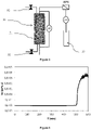
- Tests were carried out with a conventional device for measuring the permeability of porous media ( picture 3 ).
- the measuring device comprises a cell 30 comprising a sample 31 of the porous medium. In sample 31, the solution is injected aqueous gelling via the line from then a tank 33, by means of a BPR pressure regulating valve.
- the measuring device further comprises a means for measuring the pressure difference ⁇ P between the inlet and the outlet of the cell 30, and a means for measuring the pH of the gelling aqueous solution.
- the measuring device also makes it possible to rinse the connections and the downstream and upstream injection faces by means of the purges 32. Thus, only the clogging in the porous medium is measured, and not the clogging of the connections.
- the porous medium used is a representative sample of a sandstone formation with good porosity (24.5%) and average permeability (62 mD, ie 612.10 -10 m 2 ), but the test would be identical for any other medium.
- the gelling aqueous solution alkaline solution of potassium silicate+water+acetic acid
- the pH meter placed at the outlet the correct saturation of the porous medium is checked by measuring an identical pH value at the outlet with respect to the injected solution.
- the connections and the injection fittings are rinsed with fresh water, and the solution is waited for to gel, the assembly being placed at a stable regulated temperature in an oven (for example 40° C.).
- the figure 4 illustrates the evolution of the dynamic viscosity Vd (in mPa.s) of this gelling aqueous solution as a function of time T (in min).
- the gelling solution was placed in a conventional rheometer comprising a flat plate at regulated temperature (40° C.) and an oscillating cone placed above, and oscillating with a low amplitude of about ten degrees so as to do not permanently shear the liquid, which could modify its behavior.
- the force required to perform this oscillation is then measured and the viscosity can thus be deduced therefrom.
- the oscillation is greatly reduced, which makes it possible to determine the gel time.
- a permeability of 6 mD (59.10 -10 m 2 ) is measured, whereas the initial permeability of the medium porous was 62 mD (612.10 -10 m 2 ), a decrease of a factor of ten. This shows that after rupture, the porous network is permanently modified.
- a second injection can be performed.
Landscapes
- Life Sciences & Earth Sciences (AREA)
- Chemical & Material Sciences (AREA)
- Engineering & Computer Science (AREA)
- General Life Sciences & Earth Sciences (AREA)
- Organic Chemistry (AREA)
- Geology (AREA)
- Mining & Mineral Resources (AREA)
- Materials Engineering (AREA)
- Environmental & Geological Engineering (AREA)
- Geochemistry & Mineralogy (AREA)
- Physics & Mathematics (AREA)
- Fluid Mechanics (AREA)
- Chemical Kinetics & Catalysis (AREA)
- Ceramic Engineering (AREA)
- Inorganic Chemistry (AREA)
- Structural Engineering (AREA)
- Consolidation Of Soil By Introduction Of Solidifying Substances Into Soil (AREA)
- Soil Conditioners And Soil-Stabilizing Materials (AREA)
Description
- La présente invention concerne le domaine du traitement des abords d'un puits au sein d'une formation souterraine, en particulier pour un puits de stockage géologique de gaz acides, par exemple le dioxyde de carbone CO2. En particulier, l'invention concerne la fermeture de puits donnant accès aux formations géologiques dans lesquelles le stockage a lieu par injection. Un des objectifs est de prévenir les fuites, en particulier de gaz acides, par exemple de CO2, par le puits ou son voisinage.
- On connaît les procédures d'abandon de puits, dans lesquelles on introduit des bouchons de différentes qualités dans les cuvelages du puits : des bouchons mécaniques en matériau expansible, des bouchons de ciment, de résine. Cependant, la durabilité de ces matériaux, ainsi que celle du tube de cuvelage soumis à la corrosion, ne sont pas suffisantes dans le cas de stockage de gaz acides, notamment du CO2.
- On connaît aussi les injections sous pression ("squeeze") de produits spécifiques de colmatage par les perforations du puits afin d'obturer la formation poreuse et perméable. Cependant, on sait qu'il est difficile de maîtriser le placement de ces produits injectés, ce qui rend aléatoire l'efficacité du colmatage.
- En outre, on connaît la demande de brevet
WO 2010/007219 A1 , qui décrit une méthode de traitements des abords de puits de stockage de gaz acide. Pour cette méthode, on injecte dans la roche un fluide de lavage, puis une solution réactive adaptée à réagir avec des gaz acides, cette solution réactive comporte des oxydes basiques. Toutefois, cette méthode propose l'utilisation de matériaux pouvant être onéreux, pouvant polluer la formation souterraine, et pouvant nécessiter une préparation spécifique pour notamment régler la viscosité. Le documentWO2014/190226 décrit une composition et un procédé de fracturation de formations souterraines utilisant un silicate alcalin polymérisé en un gel de silice à l'aide d'un acide. Le gel de silice ainsi obtenu possède un pH d'environ 2 à moins de 7,5 et est injecté dans une formation souterraine. Le gel obtenu n'est pas injecté pour traiter les abords du puits. Le brevetUS4 438 976 décrit une méthode pour colmater des fissures dans une formation souterraine, en deux injections successives, une première comprenant un acide et une deuxième comprenant une solution qui gélifie au contact de l'acide. Cette méthode ne permet pas l'injection d'une seule solution aqueuse gélifiante pour traiter les abords du puits, mais seulement le colmatage d'un passage du fluide au sein de la formation - Afin de pallier ces inconvénients, la présente invention concerne un procédé de traitement des abords d'un puits, dans lequel on prépare, puis on injecte dans une formation souterraine, une solution aqueuse gélifiante comprenant une solution alcaline de silicate de potassium et un acide acétique. Cette solution aqueuse gélifiante permet, grâce à ces propriétés gélifiantes, de colmater les abords du puits, tout en étant peu coûteuse et peu polluante.
- L'invention concerne un procédé de traitement des abords d'un puits au sein d'une formation souterraine. Pour ce procédé, on réalise les étapes suivantes :
- a) on prépare une solution aqueuse gélifiante comprenant une solution alcaline de silicate de potassium et un acide acétique ; et
- b) on injecte à partir dudit puits dans ladite formation souterraine ladite solution aqueuse gélifiante pour traiter, au sein de ladite formation souterraine, les abords dudit puits.
- Avantageusement, on prépare une solution aqueuse gélifiante ayant une viscosité comprise entre 1 et 10 mPa.s.
- De préférence, on prépare une solution aqueuse gélifiante ayant un temps de prise compris entre 3 et 20 heures.
- Ladite solution alcaline de silicate de potassium comprend une concentration de silicium Si de 0,5 à 7 mol/L, de préférence de 0,5 à 3 mol/L. Ladite solution alcaline de silicate de potassium comprend un ratio molaire de dioxyde de silicium SiO2 par rapport à l'oxyde de potassium K2O compris entre 0,5 et 10, de préférence entre 1 et 5. Ladite solution aqueuse gélifiante comprend entre 1 et 30 % en poids d'acide acétique, de préférence entre 5 et 30 %.
- De manière avantageuse, on injecte à partir dudit puits un fluide de lavage dans ladite formation souterraine préalablement à l'injection de ladite solution aqueuse gélifiante.
- Conformément à une conception, ledit puits est un puits d'exploitation d'hydrocarbures de ladite formation souterraine, un puits de fracturation hydraulique, ou un puits de stockage, en particulier de stockage de gaz acide dans ladite formation souterraine.
- Conformément à un mode de réalisation, on stocke ledit gaz acide préalablement à l'étape d'injection de ladite solution aqueuse gélifiante.
- Alternativement, on colmate une performation et/ou au moins une fracture obtenue par fracturation, notamment, par fracturation hydraulique.
- De plus, on peut boucher ledit puits après l'étape d'injection de ladite solution aqueuse gélifiante.
- Selon une mise en œuvre, ladite formation souterraine comporte un pH environnant inférieur à 9.
- D'autres caractéristiques et avantages du procédé selon l'invention, apparaîtront à la lecture de la description ci-après d'exemples non limitatifs de réalisations, en se référant aux figures annexées et décrites ci-après.
- La
figure 1 illustre le procédé selon un premier mode de réalisation de l'invention. - La
figure 2 illustre le procédé selon un deuxième mode de réalisation de l'invention. - La
figure 3 illustre un schéma de montage expérimental pour tester une solution aqueuse gélifiante selon l'invention. - La
figure 4 illustre, pour un exemple selon l'invention, l'évolution de la viscosité dynamique en fonction du temps. - Le principe de l'invention repose sur la mise en place aux abords d'un puits, c'est-à-dire dans le voisinage du puits (en d'autres termes dans un rayon de quelques mètres autour du puits), le puits donnant accès entre la surface du sol et la formation souterraine, d'une solution permettant de limiter fortement la perméabilité de la roche du réservoir, et même de la colmater, dans ledit voisinage du puits. Ainsi, la solution injectée permet de limiter voire d'empêcher les fuites de fluides à travers le puit, et permet de former une couche protectrice pour les équipements de puits vis-à-vis des fluides, en particulier des éventuels gaz acides stockés. Il peut s'agir des fuites de gaz, notamment de gaz acides, des fuites de matières radioactives...
- La présente invention concerne donc un procédé de traitement des abords de puits au sein d'une formation souterraine, pour lequel on réalise les étapes suivantes :
- on prépare, en surface, une solution aqueuse gélifiante comprenant une solution alcaline de silicate de potassium et un acide acétique,
- on injecte, à partir du puits, dans la formation souterraine, la solution aqueuse gélifiante pour traiter, au sein de la formation souterraine, les abords du puits.
- Le procédé selon l'invention peut comporter plusieurs étapes successives, par exemple deux, d'injection de la solution aqueuse gélifiante.
- Une telle solution aqueuse gélifiante est stable et inaltérable, notamment lorsque le pH environnant (de la formation souterraine) est inférieur à 9. C'est pourquoi, le procédé selon l'invention peut, de préférence, être mis en œuvre pour une formation souterraine ayant un pH inférieur à 9, ce qui est le cas en général.
- Le terme gélifiant indique que la solution aqueuse est formulée sous forme d'un liquide non gélifié et peu visqueux, qui termine sa gélification une fois injectée dans la formation souterraine. La composition de la solution aqueuse gélifiante est donc choisie de manière à former un gel, à partir d'un temps suffisant long pour permettre le transport du liquide de la surface vers la formation souterraine. Ainsi, grâce à sa propriété gélifiante, la solution aqueuse peut remplir son rôle de limitation de perméabilité et de la porosité de la formation souterraine.
- Une solution alcaline est une solution basique qui a un pH supérieur à 7.
- On rappelle que la silice est très soluble dans les solutions alcalines, notamment dans les solutions alcalines de pH d'environ 10 et supérieur à 10. De plus, une baisse de pH provoque la précipitation de la silice contenue dans la solution alcaline : à partir d'une phase liquide dans laquelle la silice est sous une forme ionique, des oligomères se créent puis se condensent pour former un gel. Le gel a tendance à se fixer sur des surfaces minérales en formant des liaisons chimiques. Ainsi, dans une formation poreuse, l'injection de telles substances permet de réduire considérablement la perméabilité et la porosité, voire d'obstruer complètement le réseau poreux, après précipitation. En outre, les minéraux précipités par la solution aqueuse gélifiante forment aussi une couche protectrice pour les équipements de puits vis-à-vis des gaz acides stockés.
- Il existe différentes formes de silicate : de sodium, potassium, lithium, etc. Le silicate de potassium est un silicate soluble dans l'eau, de formule générale K2O5Si2. Ce silicate présente l'avantage de rendre la solution alcaline moins visqueuse que le silicate de sodium Na notamment. Ainsi, le silicate de potassium nécessite une dilution moindre, ce qui simplifie la préparation de la solution aqueuse gélifiante. De plus, étant donné que les solutions alcalines de silicate ne contiennent pas de particules, il n'y a pratiquement pas de limites d'injectivité par rapport à la taille des pores du milieu poreux de la formation souterraine. En particulier, on peut envisager l'injection d'une telle solution dans des milieux compacts présentant des seuils de pores nanométriques, améliorant ainsi encore leur capacité de barrière. En outre, la solution alcaline de silicate de potassium présente l'avantage d'être peu coûteuse, de l'ordre de quelques centaines d'Euros la tonne. Par exemple, le silicate de potassium peut être choisi par les produits commerciaux Betol K 35 T ®, Betol K 48 T ®, Betol K 54 T ® ou Betol K 28 T ® commercialisés par Woellner ® (Allemagne). A titre d'exemple non limitatif, la composition des silicates de potassium Betol K 35 T ® et Betol K 28 T ® sont décrits dans le tableau 1. Dans ce tableau, la densité, sans unité, correspond à la masse volumique rapportée à celle de l'eau.
Tableau 1 - Composition des silicates de potassium Produit SiO2 % K2O % SiO2/K2O Viscosité (cP) Densité pH Betol K 35 T ® 23.9 10.9 3.43 55 1.32 11 Betol K 28 T ® 20.5 8.2 3.92 28 1.25 10.8 - L'acide acétique, appelé également acide éthanoïque est un simple acide carboxylique avec une chaîne carbonée théorique en C2, analogue à l'éthane, de masse molaire 60 g/mol et de formule chimique brute C2H4O2 ou développée CH3COOH. Le vinaigre est un exemple de solution d'acide acétique : il peut s'agir d'un mélange d'eau et d'acide acétique. L'acide acétique présente l'avantage, contrairement à d'autres acides, de ne pas être polluant ou dangereux, que ce soit lors de sa préparation, ou injecté dans la formation souterraine.
- Selon un mode de réalisation de l'invention, la composition de la solution aqueuse gélifiante est déterminée essentiellement en fonction de la température de la formation souterraine. Par exemple, lors de la préparation, on peut modifier les proportions d'eau et d'acide pour adapter le temps de gélification tout en restant peu visqueux. En effet, les contraintes habituelles principales pour l'injection de solutions dans une formation souterraine sont les suivantes :
- une viscosité modérée de telle sorte que les pressions d'injection se situent bien en dessous des pressions de fracturation de la formation, avantageusement, la viscosité de la solution aqueuse gélifiante peut être comprise entre 1 et 10 mPa.s, et
- un temps de prise, appelé aussi temps de gélification, (c'est-à-dire le temps nécessaire entre la préparation de la solution et sa gélification) suffisant pour permettre l'injection de la solution lorsqu'elle est préparée en surface, puis injectée dans la formation, avantageusement, le temps de prise peut être compris entre 3 et 20 heures.
- Selon une mise en œuvre de l'invention, l'acide acétique peut avoir une concentration comprise entre 0,1 et 5 mol/L, de préférence entre 0,5 et 2 mol/L. Cette gamme de concentration permet notamment de préparer la solution gélifiante sans risque de générer des agrégats et une solution non homogène. Par exemple, l'acide acétique peut avoir une concentration sensiblement égale à 1 mol/L, c'est-à-dire une concentration sensiblement identique à celle d'un vinaigre. C'est la concentration d'acide pur dans la solution gélifiante qui permet de régler le temps de gélification. Ainsi, on peut diluer la solution initiale de silicate avec une plus grande quantité d'eau si un acide plus concentré est utilisé.
- Conformément à l'invention, la solution alcaline de silicate de potassium comprend une concentration de silicium Si comprise de 0,5 à 7 mol/L, de préférence de 0,5 à 3 mol/L. Cette gamme de concentration permet notamment d'obtenir des gels irréversibles stables. Par exemple, la solution alcaline de silicate de potassium commerciale peut comprendre une concentration de silicium comprise entre 4 et 5 mol/L, sensiblement égale à 4,7 mol/L. Elle peut être alors diluée avec de l'eau pour atteindre une concentration comprise entre 0,5 et 3 mol/L, sensiblement égale à 1,8 mol/L. Cette dilution fait également diminuer la viscosité de la solution vers des valeurs voisines de celle de l'eau pure.
- Selon une caractéristique de l'invention, la solution alcaline de silicate de potassium comprend un ratio molaire (SiO2/K2O) de dioxyde de silicium SiO2 par rapport à l'oxyde de potassium K2O compris entre 0,5 et 10, de préférence entre 1 et 5. Par exemple, la solution alcaline de silicate de potassium peut comprendre un ratio molaire de dioxyde de silicium SiO2 par rapport à l'oxyde de potassium K2O sensiblement égal à 4.
- La solution aqueuse gélifiante comprend entre 1 et 30 % en poids d'acide acétique, de préférence entre 10 et 20 % en poids d'acide acétique. Ainsi, il est possible de régler le pH de la solution aqueuse gélifiante. Par exemple, la solution aqueuse gélifiante peut comprendre sensiblement 16 % en poids d'acide acétique.
- Lorsque cela est utile, et en particulier lorsque la température de la formation visée est élevée, on peut encore augmenter le temps de gélification en utilisant un autre acide faible, tel que l'acide borique, ou encore en utilisant des solutions aqueuses concentrées en certains cations métalliques, telle qu'une solution d'hydroxyde d'aluminium. De manière générale, ces ions métalliques viennent se substituer partiellement au silicium dans la structure du tétraèdre de silice afin de ralentir les mécanismes de polymérisation et de condensation, augmentant les temps de gélification. La solution aqueuse gélifiante peut comprendre tout autre composé permettant notamment son adaptation à la formation souterraine.
- Pour colmater une formation poreuse autour d'un puits, on peut opérer de la manière suivante :
- on prépare, en surface, une solution aqueuse gélifiante à partir d'une solution alcaline de silicate de potassium, d'eau et d'acide acétique. De préférence, ces mélanges sont réalisés graduellement pour éviter une précipitation locale due à une concentration excessive localisée. De tels dispositifs de mélange graduel sont disponibles de manière courante, par exemple pour la préparation de gels à partir de polymères. A des températures de surface inférieures à la température prévue dans la formation souterraine (par exemple 20°C par rapport à 40 °C), la cinétique de gélification est fortement ralentie, augmentant d'autant le temps disponible pour effectuer les mélanges,
- on injecte le mélange gélifiant (la solution aqueuse gélifiante) dans la formation, en particulier par des moyens de pompage classique ; à l'amont du volume injecté (fluide contenu dans le puits), on peut utiliser de l'eau sans provoquer de précipitation. A l'aval du volume injecté, on peut, de manière identique, utiliser de l'eau.
- Un ordre de grandeur du temps de gélification de la solution aqueuse gélifiante à 40°C peut être d'environ 500 min soit 8.5 h. Cet ordre de grandeur est suffisant pour permettre de placer la solution aqueuse gélifiante dans la formation poreuse avant gélification. Par exemple, pour un volume poreux d'environ 10 m-3 dans un rayon de 1 m autour d'un puits et sur une hauteur de 10 m avec une porosité de 30% - en utilisant un débit de pompage typique de 10 m3/h, le temps d'injection nécessaire de la solution aqueuse gélifiante est de 1 heure. A cela, il faut rajouter le temps de déplacement de la solution dans le puits qui peut durer environ 3 heures suivant la technique employée et le diamètre du tube d'injection.
- Afin de laver, au sein de la formation souterraine, les abords du puits, le procédé peut comprendre une étape d'injection d'un fluide de lavage, notamment de l'eau, préalablement à l'injection de la solution aqueuse gélifiante. De plus, le fluide de lavage peut contenir des additifs visco-sifiants pour améliorer le lavage.
- Dans le cas d'un puits de stockage de gaz acides, le volume du fluide de lavage injecté est de préférence suffisant pour repousser le gaz acide à une distance radiale d'au moins quelques mètres des abords du puits. Ce rinçage, préférentiellement à l'eau, assure par la suite une bonne injectivité de la formulation comprenant le matériau réactif aux abords du puits. En l'absence de rinçage la méthode pourrait être moins efficace car il y a un risque de former rapidement des composés minéraux (carbonates et/ou sulfures) superficiels entraînant localement un bouchage de la porosité qui limiterait l'envahissement des abords de puits par la formulation réactive.
- Le procédé peut comprendre, en outre, une étape de bouchage de puits après injection de la solution aqueuse gélifiante.
- Par exemple, l'opération peut se terminer par l'injection d'un bouchon de ciment, ou toute autre formulation colmatante, pour maintenir le matériau réactif en place. Cette première opération terminée, il est possible de procéder à la même opération dans d'autres zones, en particulier au toit du réservoir après perforation du cuvelage et de la cimentation primaire de façon à permettre l'injection.
- Le procédé selon l'invention peut être appliqué à un puits de stockage de gaz acides dans la formation souterraine. Il peut être également appliqué à un puits d'exploitation ou d'exploration d'une formation souterraine comprenant des hydrocarbures. Il peut être également appliqué à un puits utilisé pour la récupération d'hydrocarbures par fracturation, notamment par fracturation hydraulique. Dans ce cas, la solution aqueuse gélifiante permet le colmatage de la perforation et/ou des fractures formées pour le procédé. Alternativement, il peut être appliqué à tout type de stockage dans une formation souterraine, par exemple pour le stockage de matières radioactives. Pour toutes les applications, le procédé selon l'invention permet notamment de limiter les fuites de gaz à travers le puits.
- L'invention s'applique en premier lieu à la fermeture d'un puits injecteur que l'on a décidé de ne plus utiliser, ce que l'on peut assimiler à l'abandon d'un puits pétrolier. Mais l'invention peut également être mise en œuvre lors de la construction d'un puits spécifiquement foré pour le stockage géologique des gaz acides, qu'il ait lieu dans des roches réservoirs, des aquifères, ou des veines de charbon.
- Les
figures 1 et 2 illustrent le procédé selon l'invention, dans le cas de l'injection de gaz acides dans une formation souterraine. Toutefois, la réalisation est sensiblement identique pour les autres applications envisagées. - La
figure 1 montre un forage 1 exécuté à travers la roche couverture 2 qui surmonte la roche réservoir 3. Le forage 1 est cuvelé par un tube 4 cimenté dans le trou foré 1 par un matériau de cimentation 5. L'accès au réservoir est obtenu par un drain foré 6. Un tube d'injection 7 se terminant par une crépine 8 est descendu dans le puits et l'annulaire entre ledit tube d'injection et le cuvelage 4 est obturé par des éléments d'étanchéité de type "packer" 9, ou équivalents, bien connus dans la profession. - Le schéma de la
figure 1 montre un exemple d'équipement de puits, nullement limitatif, d'autres variantes sont applicables à la présente invention, en particulier les "complétions" ou équipements de puits, pour des puits horizontaux. - L'injection de gaz acide est effectuée par l'intermédiaire du tube 7. Une fois le remplissage du réservoir achevé, on peut effectuer un lavage pour repousser le dioxyde de carbone CO2, ou le sulfure d'hydrogène H2S, de la zone 10 que l'on souhaite traiter. On utilise de préférence de l'eau, mais d'autres fluides peuvent être utilisés pour ce lavage dans la mesure où ils réalisent les fonctions équivalentes à celles de l'eau. Par exemple, on peut ajouter des additifs viscosifiants pour améliorer le lavage.
- Après le lavage, une solution aqueuse gélifiante est alors injectée aux abords du puits et dans un rayon de quelques mètres. Les flèches 11 schématisent ladite injection.
- Lorsque le gaz acide a tendance à retourner vers le puits, ces bases réagissent avec le gaz acide provenant du stockage, et vont minéraliser ce dernier dans les pores des milieux poreux aux abords du puits sous forme de carbonates, ou d'hydrogéno-carbonates, dans le cas du CO2, et sous forme de sulfures dans le cas de l'H2S, réduisant de cette manière la porosité et la perméabilité des abords de puits, et diminuant donc le débit de fuite potentiel de gaz acide vers la surface en passant par le puits. Les minéraux précipités forment aussi une couche protectrice pour les équipements de puits vis-à-vis des gaz acides stockés.
- L'invention s'applique également lors du forage d'un nouveau puits en vue d'y injecter des gaz acides à stocker. Dans ce cas, une fois la roche couverture du réservoir atteinte et traversée par le forage, on applique alors la méthode précédemment décrite. La
figure 2 montre un forage 21 qui a atteint la roche couverture 20, surmontant le réservoir de stockage 22. On effectue un "flush" (lavage) à l'eau, puis l'injection, juste au-dessous du niveau de la couverture (au toit du réservoir), d'une formulation gélifiante. Pour cela, on utilise une garniture de tubes 23, et un packer d'isolation de l'annulaire 24. La zone 25 est ainsi envahie d'un matériau réactif qui peut réagir en cas de fuite de gaz acide dans ladite zone. On poursuit le forage avec le fluide de forage jusqu'à la profondeur désirée, puis on procède au cuvelage et à la cimentation, puis aux perforations nécessaires à l'injection ultérieure du/des gaz acide(s). Cette méthode préventive, réalisée en amont de l'injection de CO2, permet de limiter les risques de fuites au niveau de la couverture, là où le panache de CO2 pourrait s'accumuler pendant et après l'injection, en diminuant fortement la perméabilité de la roche réservoir juste au-dessous de la couverture argileuse. Lors de la fermeture pour abandon de ce puits, la procédure décrite ci-dessus est mise en œuvre. - Les solutions aqueuses gélifiantes décrites plus haut permettent de colmater un milieu poreux. Des tests ont été effectués avec un dispositif classique permettant de mesurer la perméabilité de milieux poreux (
figure 3 ). Le dispositif de mesure comporte une cellule 30 comprenant un échantillon 31 du milieu poreux. Dans l'échantillon 31 on injecte la solution aqueuse gélifiante par la ligne de puis un réservoir 33, au moyen d'une vanne de régulation de pression BPR. Le dispositif de mesure comprend en outre un moyen de mesure de différence de pression ΔP entre l'entrée et la sortie de la cellule 30, et un moyen de mesure du pH de la solution aqueuse gélifiante. De plus, le dispositif de mesure permet en plus de rincer les connexions et les faces avales et amonts d'injection au moyen des purges 32. Ainsi, seul le colmatage dans le milieu poreux est mesuré, et non pas le bouchage des connexions. - Le milieu poreux utilisé est un échantillon représentatif d'une formation gréseuse de bonne porosité (24,5%) et de perméabilité moyenne (62 mD, soit 612. 10-10 m2), mais le test serait identique pour tout autre milieu. Après avoir mesuré la perméabilité à l'eau du milieu poreux, la solution aqueuse gélifiante (solution alcaline de silicate de potassium + eau + acide acétique) est injectée dans le milieu poreux. A l'aide du pH-mètre placé en sortie, on vérifie la bonne saturation du milieu poreux en mesurant une valeur identique de pH en sortie par rapport à la solution injectée. Puis, on rince à l'eau douce les connexions et les embouts d'injection, et on attend la gélification de la solution, l'ensemble étant placé à une température régulée stable en étuve (par exemple 40°C).
- Pour ces tests, la solution aqueuse gélifiante comporte :
- une solution alcaline de silicate de potassium industrielle (Betol K 28 T ® commercialisés par Woellner ® (Allemagne)) avec une concentration en Silicium [Si]= 4,7 mol/l et un ratio molaire SiO2/K2O=3,92,
- de l'eau, de telle sorte que la solution alcaline de silicate de potassium est diluée avec 50% poids d'eau,
- puis, 15,7% poids d'acide acétique, de concentration 1 mol/L est ajouté à la solution.
- La
figure 4 illustre l'évolution de la viscosité dynamique Vd (en mPa.s) de cette solution aqueuse gélifiante en fonction du temps T (en min). Pour cela, la solution gélifiante a été placée dans un rhéomètre classique comprenant une plaque plane à température régulée (40°C) et un cône oscillant placé au-dessus, et osc illant avec une amplitude faible d'une dizaine de degré de manière à ne pas cisailler en permanence le liquide, ce qui pourrait modifier son comportement. On mesure alors la force nécessaire pour effectuer cette oscillation et on peut ainsi en déduire la viscosité. Lorsque la solution gélifie, l'oscillation est fortement diminuée, ce qui permet de déterminer le temps de gélification. Pour cette solution, on observe que la viscosité reste identique pendant 500 minutes, puis augmente brutalement, ce qui correspond à la gélification de la solution. Visuellement et à 40°C également, la solution reste claire et transparente immédiatement après mélange. Puis graduellement, la solution devient translucide tout en restant fluide. Après 40 h, le gel formé ne coule plus lorsque le récipient (dans lequel le mélange a été initialement placé) est retourné. - En utilisant, dans le dispositif de mesure, cette formulation de la solution aqueuse gélifiante avec une proportion d'acide acétique de 15,7% et après une attente de 90h, la pression d'injection nécessaire pour obtenir la rupture du gel est de 19,5 bar (1,95MPa) pour 3 cm de carotte. Ainsi, on peut estimer le colmatage à environ 600 bar/m, soit 60 MPa/m.. En dessous de cette pression, l'eau ne peut pas traverser le milieu poreux. Des essais similaires ont montré qu'en présence d'un gaz acide tel que le CO2, les mêmes pressions de colmatage sont obtenues. Une fois la rupture du gel effectuée en appliquant une pression supérieure à 19,5 bar (1,95 MPa) dans le cas présent, une perméabilité de 6 mD (59.10-10 m2) est mesurée, alors que la perméabilité initiale du milieu poreux était de 62 mD (612. 10-10 m2), soit une diminution d'un facteur dix. Ceci montre qu'après rupture, le réseau poreux est modifié de manière permanente. Pour augmenter encore la pression de rupture et/ou diminuer encore la perméabilité, une seconde injection peut être effectuée.
Claims (9)
- Procédé de traitement des abords d'un puits au sein d'une formation souterraine, caractérisé en ce qu'on réalise les étapes suivantes :a) on prépare en surface une solution aqueuse gélifiante comprenant une solution alcaline de silicate de potassium et entre 1 et 30 % en poids d'acide acétique, de préférence entre 5 et 30 %, ladite solution alcaline de silicate de potassium comprenant une concentration de silicium Si de 0,5 à 7 mol/L, de préférence de 0,5 à 3 mol/L et un ratio molaire de dioxyde de silicium SiO2 par rapport à l'oxyde de potassium K2O compris entre 0,5 et 10, de préférence entre 1 et 5
; etb) on injecte à partir dudit puits dans ladite formation souterraine ladite solution aqueuse gélifiante pour traiter, au sein de ladite formation souterraine, les abords dudit puits. - Procédé selon la revendication 1, dans lequel on prépare une solution aqueuse gélifiante ayant une viscosité comprise entre 1 et 10 mPa.s.
- Procédé selon l'une des revendications précédentes, dans lequel on prépare une solution aqueuse gélifiante ayant un temps de prise compris entre 3 et 20 heures.
- Procédé selon l'une des revendications précédentes, dans lequel on injecte à partir dudit puits un fluide de lavage dans ladite formation souterraine préalablement à l'injection de ladite solution aqueuse gélifiante.
- Procédé selon l'une des revendications précédentes, dans lequel ledit puits est un puits d'exploitation d'hydrocarbures de ladite formation souterraine, un puits de fracturation hydraulique, ou un puits de stockage, en particulier de stockage de gaz acide dans ladite formation souterraine.
- Procédé selon la revendication 5, dans lequel on stocke ledit gaz acide préalablement à l'étape d'injection de ladite solution aqueuse gélifiante.
- Procédé selon la revendication 5, dans lequel on colmate une performation et/ou au moins une fracture obtenue par fracturation, notamment, par fracturation hydraulique.
- Procédé selon l'une des revendications précédentes, dans lequel on bouche ledit puits après l'étape d'injection de ladite solution aqueuse gélifiante.
- Procédé selon l'une des revendications précédentes, dans lequel ladite formation souterraine comporte un pH environnant inférieur à 9.
Applications Claiming Priority (2)
| Application Number | Priority Date | Filing Date | Title |
|---|---|---|---|
| FR1652923A FR3049642B1 (fr) | 2016-04-04 | 2016-04-04 | Procede de traitement des abords d'un puits au moyen d'une solution aqueuse gelifiante comprenant une solution alcaline de silicate de potassium et un acide acetique |
| PCT/EP2017/053372 WO2017174243A1 (fr) | 2016-04-04 | 2017-02-15 | Procede de traitement des abords d'un puits au moyen d'une solution aqueuse gelifiante comprenant une solution alcaline de silicate de potassium et un acide acetique |
Publications (2)
| Publication Number | Publication Date |
|---|---|
| EP3440152A1 EP3440152A1 (fr) | 2019-02-13 |
| EP3440152B1 true EP3440152B1 (fr) | 2022-07-13 |
Family
ID=56148472
Family Applications (1)
| Application Number | Title | Priority Date | Filing Date |
|---|---|---|---|
| EP17704490.6A Active EP3440152B1 (fr) | 2016-04-04 | 2017-02-15 | Procede de traitement des abords d'un puits au moyen d'une solution aqueuse gelifiante comprenant une solution alcaline de silicate de potassium et un acide acetique |
Country Status (5)
| Country | Link |
|---|---|
| US (1) | US11028310B2 (fr) |
| EP (1) | EP3440152B1 (fr) |
| CA (1) | CA3018112A1 (fr) |
| FR (1) | FR3049642B1 (fr) |
| WO (1) | WO2017174243A1 (fr) |
Families Citing this family (2)
| Publication number | Priority date | Publication date | Assignee | Title |
|---|---|---|---|---|
| FR3109601B1 (fr) | 2020-04-28 | 2022-04-15 | Ifp Energies Now | Procédé de traitement d’une formation souterraine par injection d’une solution aqueuse gélifiante comprenant un aluminate |
| WO2023015350A1 (fr) * | 2021-08-11 | 2023-02-16 | The University Of Melbourne | Séquestration de carbone |
Family Cites Families (7)
| Publication number | Priority date | Publication date | Assignee | Title |
|---|---|---|---|---|
| US4215001A (en) * | 1978-10-20 | 1980-07-29 | Halliburton Company | Methods of treating subterranean well formations |
| US4438976A (en) * | 1982-08-06 | 1984-03-27 | Occidental Research Corporation | Method of repair of short circuits for in situ leaching |
| FR2631954B1 (fr) * | 1988-05-31 | 1992-10-23 | Sif Entreprise Bachy | Procede de realisation dans le sol d'une coupure d'etancheite resistant aux acides et beton utile a cet effet |
| US7846250B2 (en) * | 2006-08-07 | 2010-12-07 | Schlumberger Technology Corporation | Geopolymer composition and application for carbon dioxide storage |
| US9701887B2 (en) * | 2006-11-28 | 2017-07-11 | Spi Technologies, Llc | Multi-component aqueous gel solution for control of delayed gelation timing and for resulting gel properties |
| WO2010107219A2 (fr) | 2009-03-16 | 2010-09-23 | Cho Won-Sang | Sac à roues comprenant des roues et des éléments de support qui peuvent coulisser conjointement dans la direction verticale |
| US20160090525A1 (en) * | 2013-05-24 | 2016-03-31 | Pq Corporation | Silica gel as a viscosifier for subterranean fluid system |
-
2016
- 2016-04-04 FR FR1652923A patent/FR3049642B1/fr not_active Expired - Fee Related
-
2017
- 2017-02-15 WO PCT/EP2017/053372 patent/WO2017174243A1/fr not_active Ceased
- 2017-02-15 US US16/090,858 patent/US11028310B2/en not_active Expired - Fee Related
- 2017-02-15 CA CA3018112A patent/CA3018112A1/fr active Pending
- 2017-02-15 EP EP17704490.6A patent/EP3440152B1/fr active Active
Also Published As
| Publication number | Publication date |
|---|---|
| US11028310B2 (en) | 2021-06-08 |
| EP3440152A1 (fr) | 2019-02-13 |
| FR3049642B1 (fr) | 2018-05-11 |
| US20200325382A1 (en) | 2020-10-15 |
| WO2017174243A1 (fr) | 2017-10-12 |
| FR3049642A1 (fr) | 2017-10-06 |
| CA3018112A1 (fr) | 2017-10-12 |
Similar Documents
| Publication | Publication Date | Title |
|---|---|---|
| CN102037210B (zh) | 利用纳米颗粒控制地下地层中的水流动 | |
| CA2911657C (fr) | Emulsion inverse pour le gonflement d'un elastomere et elimination de gateau de filtration dans un puits | |
| FR3068964A1 (fr) | Coulis de ciment geopolymerique et procede de traitement d'une formation rocheuse contre les venues de sable utilisant un tel coulis de ciment geopolymerique | |
| EP3440152B1 (fr) | Procede de traitement des abords d'un puits au moyen d'une solution aqueuse gelifiante comprenant une solution alcaline de silicate de potassium et un acide acetique | |
| EP0155859A1 (fr) | Procédé de colmatage réversible de formations souterraines | |
| EP0216661B1 (fr) | Procédé pour la prévention de la venue d'eau dans un puits producteur d'huile et/ou de gaz | |
| AU2005228173A1 (en) | Method for increasing the production of hydrocarbon liquids and gases | |
| FR3069011B1 (fr) | Procede de traitement d'une formation rocheuse contre les venues de sable utilisant un coulis de ciment geopolymerique | |
| US10414972B2 (en) | Peroxide containing formation conditioning and pressure generating composition and method | |
| FR3038600A1 (fr) | Compositions de ciment a base d'aluminophosphate de calcium a duree de vie prolongee | |
| RU2004116889A (ru) | Способ обработки призабойной зоны скважины | |
| FR2939429A1 (fr) | Materiau de cimentation pour le stockage de gaz acides | |
| CA1341360C (fr) | Composition liquide pour la production d'un gel et procede de mise en place d'un tel gel dans un puits | |
| EP4143271B1 (fr) | Procede de traitement d'une formation souterraine par injection d'une solution aqueuse gelifiante comprenant un aluminate | |
| FR2929007A1 (fr) | Methode de controle de l'integrite d'un stockage geologique contenant du co2 | |
| US2978025A (en) | Fracturing well formations | |
| US3417819A (en) | Method of fracturing with a high-viscosity liquid | |
| EP0434544B1 (fr) | Procédé et composition pour la réduction sélective de la perméabilité à l'eau dans les réservoirs d'hydrocarbures chauds et sales | |
| CA3080956A1 (fr) | Ciment microfin de haute densite pour operations de cimentation sous pression | |
| WO2012156609A1 (fr) | Produit de colmatage, et utilisation d'un tel produit | |
| CN112177584B (zh) | 一种提高深层高温碳酸盐岩裂缝有效长度和时间的方法 | |
| RU2187622C1 (ru) | Способ изоляции пластов | |
| WO2012115532A1 (fr) | Émulsions de bitume pour applications sur champs pétrolifères | |
| CN120924248A (zh) | 一种可降解液体胶塞及利用其封堵井筒的方法 | |
| CA2908791A1 (fr) | Procede de fracturation hydraulique d'une formation souterraine au moyen d'uree |
Legal Events
| Date | Code | Title | Description |
|---|---|---|---|
| STAA | Information on the status of an ep patent application or granted ep patent |
Free format text: STATUS: UNKNOWN |
|
| STAA | Information on the status of an ep patent application or granted ep patent |
Free format text: STATUS: THE INTERNATIONAL PUBLICATION HAS BEEN MADE |
|
| PUAI | Public reference made under article 153(3) epc to a published international application that has entered the european phase |
Free format text: ORIGINAL CODE: 0009012 |
|
| STAA | Information on the status of an ep patent application or granted ep patent |
Free format text: STATUS: REQUEST FOR EXAMINATION WAS MADE |
|
| 17P | Request for examination filed |
Effective date: 20181105 |
|
| AK | Designated contracting states |
Kind code of ref document: A1 Designated state(s): AL AT BE BG CH CY CZ DE DK EE ES FI FR GB GR HR HU IE IS IT LI LT LU LV MC MK MT NL NO PL PT RO RS SE SI SK SM TR |
|
| AX | Request for extension of the european patent |
Extension state: BA ME |
|
| DAV | Request for validation of the european patent (deleted) | ||
| DAX | Request for extension of the european patent (deleted) | ||
| STAA | Information on the status of an ep patent application or granted ep patent |
Free format text: STATUS: EXAMINATION IS IN PROGRESS |
|
| 17Q | First examination report despatched |
Effective date: 20200429 |
|
| GRAP | Despatch of communication of intention to grant a patent |
Free format text: ORIGINAL CODE: EPIDOSNIGR1 |
|
| STAA | Information on the status of an ep patent application or granted ep patent |
Free format text: STATUS: GRANT OF PATENT IS INTENDED |
|
| RIC1 | Information provided on ipc code assigned before grant |
Ipc: C04B 28/26 20060101ALI20220106BHEP Ipc: C09K 8/508 20060101ALI20220106BHEP Ipc: C09K 8/506 20060101ALI20220106BHEP Ipc: E21B 33/138 20060101ALI20220106BHEP Ipc: E21B 41/00 20060101ALI20220106BHEP Ipc: C09K 8/42 20060101AFI20220106BHEP |
|
| INTG | Intention to grant announced |
Effective date: 20220208 |
|
| GRAS | Grant fee paid |
Free format text: ORIGINAL CODE: EPIDOSNIGR3 |
|
| GRAA | (expected) grant |
Free format text: ORIGINAL CODE: 0009210 |
|
| STAA | Information on the status of an ep patent application or granted ep patent |
Free format text: STATUS: THE PATENT HAS BEEN GRANTED |
|
| AK | Designated contracting states |
Kind code of ref document: B1 Designated state(s): AL AT BE BG CH CY CZ DE DK EE ES FI FR GB GR HR HU IE IS IT LI LT LU LV MC MK MT NL NO PL PT RO RS SE SI SK SM TR |
|
| REG | Reference to a national code |
Ref country code: CH Ref legal event code: EP |
|
| REG | Reference to a national code |
Ref country code: DE Ref legal event code: R096 Ref document number: 602017059419 Country of ref document: DE |
|
| REG | Reference to a national code |
Ref country code: AT Ref legal event code: REF Ref document number: 1504292 Country of ref document: AT Kind code of ref document: T Effective date: 20220815 |
|
| REG | Reference to a national code |
Ref country code: IE Ref legal event code: FG4D Free format text: LANGUAGE OF EP DOCUMENT: FRENCH |
|
| REG | Reference to a national code |
Ref country code: LT Ref legal event code: MG9D |
|
| REG | Reference to a national code |
Ref country code: NL Ref legal event code: MP Effective date: 20220713 |
|
| PG25 | Lapsed in a contracting state [announced via postgrant information from national office to epo] |
Ref country code: SE Free format text: LAPSE BECAUSE OF FAILURE TO SUBMIT A TRANSLATION OF THE DESCRIPTION OR TO PAY THE FEE WITHIN THE PRESCRIBED TIME-LIMIT Effective date: 20220713 Ref country code: RS Free format text: LAPSE BECAUSE OF FAILURE TO SUBMIT A TRANSLATION OF THE DESCRIPTION OR TO PAY THE FEE WITHIN THE PRESCRIBED TIME-LIMIT Effective date: 20220713 Ref country code: PT Free format text: LAPSE BECAUSE OF FAILURE TO SUBMIT A TRANSLATION OF THE DESCRIPTION OR TO PAY THE FEE WITHIN THE PRESCRIBED TIME-LIMIT Effective date: 20221114 Ref country code: NO Free format text: LAPSE BECAUSE OF FAILURE TO SUBMIT A TRANSLATION OF THE DESCRIPTION OR TO PAY THE FEE WITHIN THE PRESCRIBED TIME-LIMIT Effective date: 20221013 Ref country code: NL Free format text: LAPSE BECAUSE OF FAILURE TO SUBMIT A TRANSLATION OF THE DESCRIPTION OR TO PAY THE FEE WITHIN THE PRESCRIBED TIME-LIMIT Effective date: 20220713 Ref country code: LV Free format text: LAPSE BECAUSE OF FAILURE TO SUBMIT A TRANSLATION OF THE DESCRIPTION OR TO PAY THE FEE WITHIN THE PRESCRIBED TIME-LIMIT Effective date: 20220713 Ref country code: LT Free format text: LAPSE BECAUSE OF FAILURE TO SUBMIT A TRANSLATION OF THE DESCRIPTION OR TO PAY THE FEE WITHIN THE PRESCRIBED TIME-LIMIT Effective date: 20220713 Ref country code: FI Free format text: LAPSE BECAUSE OF FAILURE TO SUBMIT A TRANSLATION OF THE DESCRIPTION OR TO PAY THE FEE WITHIN THE PRESCRIBED TIME-LIMIT Effective date: 20220713 Ref country code: ES Free format text: LAPSE BECAUSE OF FAILURE TO SUBMIT A TRANSLATION OF THE DESCRIPTION OR TO PAY THE FEE WITHIN THE PRESCRIBED TIME-LIMIT Effective date: 20220713 |
|
| REG | Reference to a national code |
Ref country code: AT Ref legal event code: MK05 Ref document number: 1504292 Country of ref document: AT Kind code of ref document: T Effective date: 20220713 |
|
| PG25 | Lapsed in a contracting state [announced via postgrant information from national office to epo] |
Ref country code: PL Free format text: LAPSE BECAUSE OF FAILURE TO SUBMIT A TRANSLATION OF THE DESCRIPTION OR TO PAY THE FEE WITHIN THE PRESCRIBED TIME-LIMIT Effective date: 20220713 Ref country code: IS Free format text: LAPSE BECAUSE OF FAILURE TO SUBMIT A TRANSLATION OF THE DESCRIPTION OR TO PAY THE FEE WITHIN THE PRESCRIBED TIME-LIMIT Effective date: 20221113 Ref country code: HR Free format text: LAPSE BECAUSE OF FAILURE TO SUBMIT A TRANSLATION OF THE DESCRIPTION OR TO PAY THE FEE WITHIN THE PRESCRIBED TIME-LIMIT Effective date: 20220713 Ref country code: GR Free format text: LAPSE BECAUSE OF FAILURE TO SUBMIT A TRANSLATION OF THE DESCRIPTION OR TO PAY THE FEE WITHIN THE PRESCRIBED TIME-LIMIT Effective date: 20221014 |
|
| REG | Reference to a national code |
Ref country code: DE Ref legal event code: R097 Ref document number: 602017059419 Country of ref document: DE |
|
| PG25 | Lapsed in a contracting state [announced via postgrant information from national office to epo] |
Ref country code: SM Free format text: LAPSE BECAUSE OF FAILURE TO SUBMIT A TRANSLATION OF THE DESCRIPTION OR TO PAY THE FEE WITHIN THE PRESCRIBED TIME-LIMIT Effective date: 20220713 Ref country code: RO Free format text: LAPSE BECAUSE OF FAILURE TO SUBMIT A TRANSLATION OF THE DESCRIPTION OR TO PAY THE FEE WITHIN THE PRESCRIBED TIME-LIMIT Effective date: 20220713 Ref country code: DK Free format text: LAPSE BECAUSE OF FAILURE TO SUBMIT A TRANSLATION OF THE DESCRIPTION OR TO PAY THE FEE WITHIN THE PRESCRIBED TIME-LIMIT Effective date: 20220713 Ref country code: CZ Free format text: LAPSE BECAUSE OF FAILURE TO SUBMIT A TRANSLATION OF THE DESCRIPTION OR TO PAY THE FEE WITHIN THE PRESCRIBED TIME-LIMIT Effective date: 20220713 Ref country code: AT Free format text: LAPSE BECAUSE OF FAILURE TO SUBMIT A TRANSLATION OF THE DESCRIPTION OR TO PAY THE FEE WITHIN THE PRESCRIBED TIME-LIMIT Effective date: 20220713 |
|
| PLBE | No opposition filed within time limit |
Free format text: ORIGINAL CODE: 0009261 |
|
| STAA | Information on the status of an ep patent application or granted ep patent |
Free format text: STATUS: NO OPPOSITION FILED WITHIN TIME LIMIT |
|
| PG25 | Lapsed in a contracting state [announced via postgrant information from national office to epo] |
Ref country code: SK Free format text: LAPSE BECAUSE OF FAILURE TO SUBMIT A TRANSLATION OF THE DESCRIPTION OR TO PAY THE FEE WITHIN THE PRESCRIBED TIME-LIMIT Effective date: 20220713 Ref country code: EE Free format text: LAPSE BECAUSE OF FAILURE TO SUBMIT A TRANSLATION OF THE DESCRIPTION OR TO PAY THE FEE WITHIN THE PRESCRIBED TIME-LIMIT Effective date: 20220713 |
|
| 26N | No opposition filed |
Effective date: 20230414 |
|
| PG25 | Lapsed in a contracting state [announced via postgrant information from national office to epo] |
Ref country code: AL Free format text: LAPSE BECAUSE OF FAILURE TO SUBMIT A TRANSLATION OF THE DESCRIPTION OR TO PAY THE FEE WITHIN THE PRESCRIBED TIME-LIMIT Effective date: 20220713 |
|
| P01 | Opt-out of the competence of the unified patent court (upc) registered |
Effective date: 20230712 |
|
| PG25 | Lapsed in a contracting state [announced via postgrant information from national office to epo] |
Ref country code: SI Free format text: LAPSE BECAUSE OF FAILURE TO SUBMIT A TRANSLATION OF THE DESCRIPTION OR TO PAY THE FEE WITHIN THE PRESCRIBED TIME-LIMIT Effective date: 20220713 |
|
| REG | Reference to a national code |
Ref country code: DE Ref legal event code: R119 Ref document number: 602017059419 Country of ref document: DE |
|
| PG25 | Lapsed in a contracting state [announced via postgrant information from national office to epo] |
Ref country code: MC Free format text: LAPSE BECAUSE OF FAILURE TO SUBMIT A TRANSLATION OF THE DESCRIPTION OR TO PAY THE FEE WITHIN THE PRESCRIBED TIME-LIMIT Effective date: 20220713 |
|
| REG | Reference to a national code |
Ref country code: CH Ref legal event code: PL |
|
| REG | Reference to a national code |
Ref country code: BE Ref legal event code: MM Effective date: 20230228 |
|
| GBPC | Gb: european patent ceased through non-payment of renewal fee |
Effective date: 20230215 |
|
| PG25 | Lapsed in a contracting state [announced via postgrant information from national office to epo] |
Ref country code: LU Free format text: LAPSE BECAUSE OF NON-PAYMENT OF DUE FEES Effective date: 20230215 Ref country code: LI Free format text: LAPSE BECAUSE OF NON-PAYMENT OF DUE FEES Effective date: 20230228 Ref country code: CH Free format text: LAPSE BECAUSE OF NON-PAYMENT OF DUE FEES Effective date: 20230228 |
|
| REG | Reference to a national code |
Ref country code: IE Ref legal event code: MM4A |
|
| PG25 | Lapsed in a contracting state [announced via postgrant information from national office to epo] |
Ref country code: GB Free format text: LAPSE BECAUSE OF NON-PAYMENT OF DUE FEES Effective date: 20230215 |
|
| PG25 | Lapsed in a contracting state [announced via postgrant information from national office to epo] |
Ref country code: IT Free format text: LAPSE BECAUSE OF FAILURE TO SUBMIT A TRANSLATION OF THE DESCRIPTION OR TO PAY THE FEE WITHIN THE PRESCRIBED TIME-LIMIT Effective date: 20220713 Ref country code: IE Free format text: LAPSE BECAUSE OF NON-PAYMENT OF DUE FEES Effective date: 20230215 Ref country code: GB Free format text: LAPSE BECAUSE OF NON-PAYMENT OF DUE FEES Effective date: 20230215 Ref country code: FR Free format text: LAPSE BECAUSE OF NON-PAYMENT OF DUE FEES Effective date: 20230228 Ref country code: DE Free format text: LAPSE BECAUSE OF NON-PAYMENT OF DUE FEES Effective date: 20230901 |
|
| PG25 | Lapsed in a contracting state [announced via postgrant information from national office to epo] |
Ref country code: BE Free format text: LAPSE BECAUSE OF NON-PAYMENT OF DUE FEES Effective date: 20230228 |
|
| PG25 | Lapsed in a contracting state [announced via postgrant information from national office to epo] |
Ref country code: BG Free format text: LAPSE BECAUSE OF FAILURE TO SUBMIT A TRANSLATION OF THE DESCRIPTION OR TO PAY THE FEE WITHIN THE PRESCRIBED TIME-LIMIT Effective date: 20220713 |
|
| PG25 | Lapsed in a contracting state [announced via postgrant information from national office to epo] |
Ref country code: BG Free format text: LAPSE BECAUSE OF FAILURE TO SUBMIT A TRANSLATION OF THE DESCRIPTION OR TO PAY THE FEE WITHIN THE PRESCRIBED TIME-LIMIT Effective date: 20220713 |
|
| PG25 | Lapsed in a contracting state [announced via postgrant information from national office to epo] |
Ref country code: CY Free format text: LAPSE BECAUSE OF FAILURE TO SUBMIT A TRANSLATION OF THE DESCRIPTION OR TO PAY THE FEE WITHIN THE PRESCRIBED TIME-LIMIT; INVALID AB INITIO Effective date: 20170215 |
|
| PG25 | Lapsed in a contracting state [announced via postgrant information from national office to epo] |
Ref country code: HU Free format text: LAPSE BECAUSE OF FAILURE TO SUBMIT A TRANSLATION OF THE DESCRIPTION OR TO PAY THE FEE WITHIN THE PRESCRIBED TIME-LIMIT; INVALID AB INITIO Effective date: 20170215 |
|
| PG25 | Lapsed in a contracting state [announced via postgrant information from national office to epo] |
Ref country code: TR Free format text: LAPSE BECAUSE OF FAILURE TO SUBMIT A TRANSLATION OF THE DESCRIPTION OR TO PAY THE FEE WITHIN THE PRESCRIBED TIME-LIMIT Effective date: 20220713 |