EP3440239B1 - Membrane conductrice d'ions - Google Patents
Membrane conductrice d'ions Download PDFInfo
- Publication number
- EP3440239B1 EP3440239B1 EP17720603.4A EP17720603A EP3440239B1 EP 3440239 B1 EP3440239 B1 EP 3440239B1 EP 17720603 A EP17720603 A EP 17720603A EP 3440239 B1 EP3440239 B1 EP 3440239B1
- Authority
- EP
- European Patent Office
- Prior art keywords
- membrane
- cathode
- solution
- membranes
- anode
- Prior art date
- Legal status (The legal status is an assumption and is not a legal conclusion. Google has not performed a legal analysis and makes no representation as to the accuracy of the status listed.)
- Active
Links
- MCTWTZJPVLRJOU-UHFFFAOYSA-N C[n]1cncc1 Chemical compound C[n]1cncc1 MCTWTZJPVLRJOU-UHFFFAOYSA-N 0.000 description 1
Images
Classifications
-
- C—CHEMISTRY; METALLURGY
- C08—ORGANIC MACROMOLECULAR COMPOUNDS; THEIR PREPARATION OR CHEMICAL WORKING-UP; COMPOSITIONS BASED THEREON
- C08J—WORKING-UP; GENERAL PROCESSES OF COMPOUNDING; AFTER-TREATMENT NOT COVERED BY SUBCLASSES C08B, C08C, C08F, C08G or C08H
- C08J5/00—Manufacture of articles or shaped materials containing macromolecular substances
- C08J5/20—Manufacture of shaped structures of ion-exchange resins
- C08J5/22—Films, membranes or diaphragms
- C08J5/2206—Films, membranes or diaphragms based on organic and/or inorganic macromolecular compounds
- C08J5/2218—Synthetic macromolecular compounds
- C08J5/2268—Synthetic macromolecular compounds based on macromolecular compounds obtained by reactions involving unsaturated carbon-to-carbon bonds, and by reactions not involving this type of bond
-
- C—CHEMISTRY; METALLURGY
- C25—ELECTROLYTIC OR ELECTROPHORETIC PROCESSES; APPARATUS THEREFOR
- C25B—ELECTROLYTIC OR ELECTROPHORETIC PROCESSES FOR THE PRODUCTION OF COMPOUNDS OR NON-METALS; APPARATUS THEREFOR
- C25B13/00—Diaphragms; Spacing elements
- C25B13/04—Diaphragms; Spacing elements characterised by the material
- C25B13/08—Diaphragms; Spacing elements characterised by the material based on organic materials
-
- C—CHEMISTRY; METALLURGY
- C25—ELECTROLYTIC OR ELECTROPHORETIC PROCESSES; APPARATUS THEREFOR
- C25B—ELECTROLYTIC OR ELECTROPHORETIC PROCESSES FOR THE PRODUCTION OF COMPOUNDS OR NON-METALS; APPARATUS THEREFOR
- C25B3/00—Electrolytic production of organic compounds
- C25B3/20—Processes
- C25B3/25—Reduction
-
- C—CHEMISTRY; METALLURGY
- C25—ELECTROLYTIC OR ELECTROPHORETIC PROCESSES; APPARATUS THEREFOR
- C25B—ELECTROLYTIC OR ELECTROPHORETIC PROCESSES FOR THE PRODUCTION OF COMPOUNDS OR NON-METALS; APPARATUS THEREFOR
- C25B3/00—Electrolytic production of organic compounds
- C25B3/20—Processes
- C25B3/25—Reduction
- C25B3/26—Reduction of carbon dioxide
-
- C—CHEMISTRY; METALLURGY
- C25—ELECTROLYTIC OR ELECTROPHORETIC PROCESSES; APPARATUS THEREFOR
- C25B—ELECTROLYTIC OR ELECTROPHORETIC PROCESSES FOR THE PRODUCTION OF COMPOUNDS OR NON-METALS; APPARATUS THEREFOR
- C25B9/00—Cells or assemblies of cells; Constructional parts of cells; Assemblies of constructional parts, e.g. electrode-diaphragm assemblies; Process-related cell features
- C25B9/17—Cells comprising dimensionally-stable non-movable electrodes; Assemblies of constructional parts thereof
- C25B9/19—Cells comprising dimensionally-stable non-movable electrodes; Assemblies of constructional parts thereof with diaphragms
- C25B9/23—Cells comprising dimensionally-stable non-movable electrodes; Assemblies of constructional parts thereof with diaphragms comprising ion-exchange membranes in or on which electrode material is embedded
-
- H—ELECTRICITY
- H01—ELECTRIC ELEMENTS
- H01M—PROCESSES OR MEANS, e.g. BATTERIES, FOR THE DIRECT CONVERSION OF CHEMICAL ENERGY INTO ELECTRICAL ENERGY
- H01M8/00—Fuel cells; Manufacture thereof
- H01M8/10—Fuel cells with solid electrolytes
- H01M8/1016—Fuel cells with solid electrolytes characterised by the electrolyte material
- H01M8/1018—Polymeric electrolyte materials
- H01M8/102—Polymeric electrolyte materials characterised by the chemical structure of the main chain of the ion-conducting polymer
- H01M8/1023—Polymeric electrolyte materials characterised by the chemical structure of the main chain of the ion-conducting polymer having only carbon, e.g. polyarylenes, polystyrenes or polybutadiene-styrenes
-
- H—ELECTRICITY
- H01—ELECTRIC ELEMENTS
- H01M—PROCESSES OR MEANS, e.g. BATTERIES, FOR THE DIRECT CONVERSION OF CHEMICAL ENERGY INTO ELECTRICAL ENERGY
- H01M8/00—Fuel cells; Manufacture thereof
- H01M8/10—Fuel cells with solid electrolytes
- H01M8/1016—Fuel cells with solid electrolytes characterised by the electrolyte material
- H01M8/1018—Polymeric electrolyte materials
- H01M8/102—Polymeric electrolyte materials characterised by the chemical structure of the main chain of the ion-conducting polymer
- H01M8/1027—Polymeric electrolyte materials characterised by the chemical structure of the main chain of the ion-conducting polymer having carbon, oxygen and other atoms, e.g. sulfonated polyethersulfones [S-PES]
-
- C—CHEMISTRY; METALLURGY
- C08—ORGANIC MACROMOLECULAR COMPOUNDS; THEIR PREPARATION OR CHEMICAL WORKING-UP; COMPOSITIONS BASED THEREON
- C08J—WORKING-UP; GENERAL PROCESSES OF COMPOUNDING; AFTER-TREATMENT NOT COVERED BY SUBCLASSES C08B, C08C, C08F, C08G or C08H
- C08J2325/00—Characterised by the use of homopolymers or copolymers of compounds having one or more unsaturated aliphatic radicals, each having only one carbon-to-carbon double bond, and at least one being terminated by an aromatic carbocyclic ring; Derivatives of such polymers
- C08J2325/02—Homopolymers or copolymers of hydrocarbons
- C08J2325/04—Homopolymers or copolymers of styrene
- C08J2325/06—Polystyrene
-
- C—CHEMISTRY; METALLURGY
- C25—ELECTROLYTIC OR ELECTROPHORETIC PROCESSES; APPARATUS THEREFOR
- C25B—ELECTROLYTIC OR ELECTROPHORETIC PROCESSES FOR THE PRODUCTION OF COMPOUNDS OR NON-METALS; APPARATUS THEREFOR
- C25B1/00—Electrolytic production of inorganic compounds or non-metals
- C25B1/01—Products
- C25B1/02—Hydrogen or oxygen
- C25B1/04—Hydrogen or oxygen by electrolysis of water
-
- H—ELECTRICITY
- H01—ELECTRIC ELEMENTS
- H01M—PROCESSES OR MEANS, e.g. BATTERIES, FOR THE DIRECT CONVERSION OF CHEMICAL ENERGY INTO ELECTRICAL ENERGY
- H01M8/00—Fuel cells; Manufacture thereof
- H01M8/10—Fuel cells with solid electrolytes
- H01M2008/1095—Fuel cells with polymeric electrolytes
-
- Y—GENERAL TAGGING OF NEW TECHNOLOGICAL DEVELOPMENTS; GENERAL TAGGING OF CROSS-SECTIONAL TECHNOLOGIES SPANNING OVER SEVERAL SECTIONS OF THE IPC; TECHNICAL SUBJECTS COVERED BY FORMER USPC CROSS-REFERENCE ART COLLECTIONS [XRACs] AND DIGESTS
- Y02—TECHNOLOGIES OR APPLICATIONS FOR MITIGATION OR ADAPTATION AGAINST CLIMATE CHANGE
- Y02E—REDUCTION OF GREENHOUSE GAS [GHG] EMISSIONS, RELATED TO ENERGY GENERATION, TRANSMISSION OR DISTRIBUTION
- Y02E60/00—Enabling technologies; Technologies with a potential or indirect contribution to GHG emissions mitigation
- Y02E60/30—Hydrogen technology
- Y02E60/36—Hydrogen production from non-carbon containing sources, e.g. by water electrolysis
-
- Y—GENERAL TAGGING OF NEW TECHNOLOGICAL DEVELOPMENTS; GENERAL TAGGING OF CROSS-SECTIONAL TECHNOLOGIES SPANNING OVER SEVERAL SECTIONS OF THE IPC; TECHNICAL SUBJECTS COVERED BY FORMER USPC CROSS-REFERENCE ART COLLECTIONS [XRACs] AND DIGESTS
- Y02—TECHNOLOGIES OR APPLICATIONS FOR MITIGATION OR ADAPTATION AGAINST CLIMATE CHANGE
- Y02E—REDUCTION OF GREENHOUSE GAS [GHG] EMISSIONS, RELATED TO ENERGY GENERATION, TRANSMISSION OR DISTRIBUTION
- Y02E60/00—Enabling technologies; Technologies with a potential or indirect contribution to GHG emissions mitigation
- Y02E60/30—Hydrogen technology
- Y02E60/50—Fuel cells
Definitions
- the field of the invention is electrochemistry.
- the devices, systems and compositions described involve the electrochemical conversion of carbon dioxide into useful products, the electrolysis of water, electric power generation using fuel cells and electrochemical water purification.
- CO 2 carbon dioxide
- One solution known as carbon sequestration, involves the capture and storage of CO 2 . Often the CO 2 is simply buried. It would be beneficial if instead of simply burying or storing the CO 2 , it could be converted into another product and put to a beneficial use.
- Patent App. Pub. No. 2008/0223727 Hori, Y., "Electrochemical CO2 reduction on metal electrodes", Modern Aspects of Electrochemistry 42 (2008), pages 89-189 ; Gattrell, M. et al. "A review of the aqueous electrochemical reduction of CO2 to hydrocarbons at copper”, Journal of Electroanalytical Chemistry 594 (2006), pages 1-19 ; and DuBois, D., Encyclopedia of Electrochemistry, 7a, Springer (2006), pages 202-225 .
- US2012171583A1 discloses methods and systems for gas phase electrochemical reduction of carbon dioxide and the use of polyvinylpyridinium in the membrane.
- an electrochemical cell contains an anode, a cathode and an electrolyte. Catalysts can be placed on the anode, the cathode, and/or in the electrolyte to promote the desired chemical reactions. During operation, reactants or a solution containing reactants are fed into the cell. Voltage is then applied between the anode and the cathode, to promote the desired electrochemical reaction.
- a reactant comprising CO 2 , carbonate or bicarbonate is fed into the cell.
- a voltage is applied to the cell, and the CO 2 reacts to form new chemical compounds.
- U.S. Patent Nos. 4,523,981 ; 4,545,872 ; and 4,620,906 disclose the use of a solid polymer electrolyte membrane, typically a cation exchange membrane, wherein the anode and cathode are separated by the cation exchange membrane. More recent examples of this technique include U.S. Patent Nos.
- Prakash G., et al. "Electrochemical reduction of CO2 over Sn-Nafion coated electrode for a fuel-cell-like device", Journal of Power Sources 223 (2013), pages 68-73 (“Prakash”), discusses the advantages of using a liquid free cathode in a cation exchange membrane style CO 2 electrolyzer although it fails to teach a liquid free cathode. Instead, a liquid solution is fed into the cathode in the experiments discussed in Prakash.
- liquid free cathode electrolyzer no bulk liquids are in direct contact with the cathode during electrolysis, however there can be a thin liquid film on or in the cathode. In addition, the occasional wash or rehydration of the cathode with liquids may occur. Advantages of using a liquid free cathode included better CO 2 mass transfer and reduced parasitic resistance.
- Dewolf, D., et al. "The electrochemical reduction of CO2 to CH4 and C2H4 at Cu/Nafion electrodes (solid polymer electrolyte structures)" Catalysis Letters 1 (1988), pages 73-80 (“Dewolf'), discloses the use of a liquid free cathode in a cation exchange membrane electrolyzer: an electrolyzer with a cation-conducting polymer electrolyte membrane separating the anode from the cathode.
- Dewolf reports an observed maximum faradaic efficiency (the fraction of the electrons applied to the cell that participate in reactions producing carbon containing products) of 19% for CO 2 conversion into useful products and a small steady state current of 1 mA/cm 2 .
- the cm 2 is measured as the area of the cathode gas diffusion layer that is covered by catalyst particles.
- a system can have a high coulombic efficiency for the production of species adsorbed on the electrocatalyst, but may only observe a small faradaic efficiency (0.03% in Shironita I and Shironita II) for products that leave the catalyst layer.
- This phenomenon is adequately explained in Rosen, B.A., et al., "In Situ Spectroscopic Examination of a Low Overpotential Pathway for Carbon Dioxide Conversion to Carbon Monoxide", J. Phys. Chem. C, 116 (2012), pages 15307-15312 , which found that when CO 2 is reduced to adsorbed CO during CO 2 conversion by cyclic voltammetry, most of the CO does not leave the electrolyzer.
- R s is selected from the group consisting of imidazoliums, pyridiniums, pyrazoliums, pyrrolidiniums, pyrroliums, pyrimidiums, piperidiniums, indoliums, triaziniums, preferably imidazoliums and pyridiniums.
- R s is an imidazolium.
- the imidazolium is preferably an alkylimidazolium, more preferably tetramethylimidazolium.
- R s is a pyridinium.
- the pyridinium is preferably an alkylpyridinium, more preferably pentamethylpyridinium.
- the polymer will have a molecular weight between 1000 and 10,000,000 atomic units (A.U.) preferably between 10,000 and 1,000,000 A.U., most preferably between 25,000 and 250,000 A.U.
- the polymeric composition is in the form of a membrane.
- the membrane has a preferred thickness of 10 - 300 micrometers.
- the polymer can be classified as a Helper Membrane.
- a membrane can be classified as a Helper Membrane if it meets the following test:
- any numerical value ranges recited herein include all values from the lower value to the upper value in increments of one unit, provided that there is a separation of at least two units between any lower value and any higher value.
- concentration of a component or value of a process variable such as, for example, size, angle size, pressure, time and the like, is, for example, from 1 to 98, specifically from 20 to 80, more specifically from 30 to 70, it is intended that values such as 15 to 85, 22 to 68, 43 to 51, 30 to 32, and the like, are expressly enumerated in this specification.
- one unit is considered to be 0.0001, 0.001, 0.01 or 0.1 as appropriate.
- electrochemical conversion of CO 2 refers to any electrochemical process where carbon dioxide, carbonate, or bicarbonate is converted into another chemical substance in any step of the process.
- polymer electrolyte membrane refers to both cation exchange membranes, which generally comprise polymers having multiple covalently attached negatively charged groups, and anion exchange membranes, which generally comprise polymers having multiple covalently attached positively charged groups.
- Typical cation exchange membranes include proton conducting membranes, such as the perfluorosulfonic acid polymer available under the trade designation NAFION from E. I. du Pont de Nemours and Company (DuPont) of Wilmington, DE.
- anion exchange membrane electrolyzer refers to an electrolyzer with an anion-conducting polymer electrolyte membrane separating the anode from the cathode.
- liquid free cathode refers to an electrolyzer where there are no bulk liquids in direct contact with the cathode during electrolysis. There can be a thin liquid film on or in the cathode, however, and occasional wash, or rehydration of the cathode with liquids could occur.
- radar efficiency refers to the fraction of the electrons applied to the cell that participate in reactions producing carbon containing products.
- EMIM 1-ethyl-3-methylimidazolium cations
- Hydrogen Evolution Reaction also called “HER” as used here refers to the electrochemical reaction 2H + + 2e - ⁇ H 2 .
- MEA membrane electrode assembly
- CV refers to cyclic voltammetry
- Millipore water is water that is produced by a Millipore filtration system with a resistivity of at least 18.2 megaohm-cm.
- SPEEK refers to sulfonated poly (ether ether ketone).
- PVA polyvinyl alcohol
- PEI polyethylenimine
- GC gas chromatograph
- imidazolium refers to a positively charged ligand containing an imidazole group. This includes a bare imidazole or a substituted imidazole.
- pyridinium refers to a positively charged ligand containing a pyridine group. This includes a bare pyridine or a substituted pyridine.
- phosphonium refers to a positively charged ligand containing phosphorous. This includes substituted phosphorous.
- positively charged cyclic amine refers to a positively charged ligand containing a cyclic amine. This specifically includes imidazoliums, pyridiniums, pyrazoliums, pyrrolidiniums, pyrroliums, pyrimidiums, piperidiniums, indoliums, triaziniums, and polymers thereof, such as the vinyl benzyl copolymers described herein, are specifically included.
- R 16 , R 17 and R 18 are each independently selected from hydrogen, linear alkyls, branched alkyls, cyclic alkyls, heteroalkyls, aryls, heteroaryls, alkylaryls, heteroalkylaryls, but not polymers.
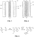
- FIG. 1 illustrates a fuel cell hardware assembly 30, which includes a membrane electrode assembly 32 interposed between rigid flow field plates 34 and 36, typically formed of graphite or a graphite composite material.
- Membrane electrode assembly 32 consists of a polymer electrolyte (ion exchange) membrane 42 interposed between two electrodes, namely, anode 44 and cathode 46.
- Anode 44 and cathode 46 are typically formed of porous electrically conductive sheet material, preferably carbon fiber paper, and have planar maj or surfaces. Electrodes 44 and 46 have a thin layer of catalyst material disposed on their major surfaces at the interface with membrane 42 to render them electrochemically active.
- anode flow field plate 34 has at least one open faced channel 34a engraved, milled or molded in its major surface facing membrane 42.
- cathode flow field plate 36 has at least one open faced channel 36a engraved, milled or molded in its major surface facing membrane 42.
- a fuel cell hardware assembly 50 employs a membrane electrode assembly 52 having integral reactant fluid flow channels.
- Fuel cell hardware assembly 50 includes membrane electrode assembly 52 interposed between lightweight separator layers 54 and 56, which are substantially impermeable to the flow of reactant fluid therethrough.
- Membrane electrode assembly 52 consists of a polymer electrolyte (ion exchange) membrane 62 interposed between two electrodes, namely, anode 64 and cathode 66.
- Anode 64 and cathode 66 are formed of porous electrically conductive sheet material, preferably carbon fiber paper. Electrodes 64 and 66 have a thin layer of catalyst material disposed on their major surfaces at the interface with membrane 62 to render them electrochemically active.
- anode 64 has at least one open faced channel 64a formed in its surface facing away from membrane 62.
- cathode 66 has at least one open faced channel 66a formed in its surface facing away from membrane 62.
- channels 64a and 66a form the reactant flow field passages for the fuel and oxidant streams, respectively.
- reactants or a solution containing reactants is fed into the cell. Then a voltage is applied between the anode and the cathode, to promote an electrochemical reaction.
- reactants or a solution containing reactants is fed into the fuel cell hardware assembly, and a voltage spontaneously develops between the anode and cathode.
- This voltage can produce a current through an external circuit connecting the anode and cathode.
- a reactant comprising CO 2 , carbonate or bicarbonate is fed into the cell.
- a voltage is applied to the cell, and the CO 2 reacts to form new chemical compounds.
- the present electrochemical device for electrochemical conversion of CO 2 , water, carbonate, and/or bicarbonate into another chemical substance has an anode, a cathode, and a Helper Membrane.
- the faradaic efficiency for CO 2 conversion is at least 33%, more preferably at least 50%, or most preferably at least 80%.
- the device can also include at least one Catalytically Active Element.
- Catalytically Active Element refers to a chemical element that can serve as a catalyst for the electrochemical conversion of CO 2 or another species of interest in a desired reaction.
- the device can include one or more of the following Catalytically Active Elements: V, Cr, Mn, Fe, Co, Ni, Cu, Sn, Zr, Nb, Mo, Ru, Rh, Pd, Ag, Cd, Hf, Ta, W, Re, Ir, Pt, Au, Hg, Al, Si, In, Tl, Pb, Bi, Sb, Te, U, Sm, Tb, La, Ce, and Nd.
- Specific Example 1 illustrates a procedure to create an electrolyzer with a Helper Membrane.
- the embodiment of Specific Example 1 demonstrates improved performance over earlier electrochemical cells used for CO 2 conversion.
- the cathode in Specific Example 1 was prepared as follows. Silver ink was made by mixing 30 mg of silver nanoparticles (20-40 nm, 45509, Alfa Aesar, Ward Hill, MA) with 0.1 ml deionized water (18.2 Mohm, EMD Millipore, Billerica, MA) and 0.2 ml isopropanol (3032-16, Cell Fine Chemicals, Avantor Performance Materials, Center Valley, PA). The mixture was then sonicated for 1 minute. The silver ink was then hand-painted onto a gas diffusion layer (Sigracet 35 BC GDL, Ion Power Inc., New Castle, DE) covering an area of 2.5 cm x 2.5 cm.
- a gas diffusion layer Sigracet 35 BC GDL, Ion Power Inc., New Castle, DE
- the anode in Specific Example 1 was prepared as follows. RuO 2 ink was made by mixing 15 mg of RuO 2 (11804, Alfa Aesar) with 0.2 ml deionized water (18.2 Mohm Millipore), 0.2 ml isopropanol (3032-16, Macron) and 0.1 ml of 5% Nafion solution (1100EW, DuPont, Wilmington, DE). The RuO 2 ink was then hand-painted onto a gas diffusion layer (Sigracet 35 BC GDL, Ion Power, Inc.) covering an area of 2.5 cm x 2.5 cm.
- a gas diffusion layer Sigracet 35 BC GDL, Ion Power, Inc.
- PSMMIM refers to a co-polymer of polystyrene and poly l-(p-vinylbenzyl)-3-methylimidazolium: where X - is an anion and m > 0 and n > 0.
- the first inhibitor free styrene was prepared by washing styrene (Sigma-Aldrich, Saint Louis, MO) with two equal volumes of 7.5% aqueous sodium hydroxide. The inhibitor free styrene was then washed with four equal volumes of water to make sure it was neutralized, and was then dried over anhydrous magnesium sulfate. Inhibitor TBC in 4-vinylbenzyl chloride (4-VBC) was removed by extraction with 0.5% potassium hydroxide solution until a colorless extract was obtained. This extract was washed with water until neutral and then was dried over anhydrous magnesium sulfate.
- Poly(4-vinylbenzyl chloride-co-styrene) was then synthesized by heating a solution of inhibitor free styrene (Sigma-Aldrich) (10.0581 g, 96.57 mmol) and 4-vinylbenzyl chloride (Sigma-Aldrich) (6.2323 g, 40.84 mmol) in chlorobenzene (Sigma-Aldrich) (15 ml) at 60-65°C in an oil bath for 12-18 hours under argon gas with AIBN ( ⁇ , ⁇ '-Azoisobutyronitrile, Sigma-Aldrich) (0.1613 g, 0.99 wt% based on the total monomers weight) as initiator.
- the copolymer was precipitated in CH 3 OH/THF (methanol/tetrahydrofuran) and dried under vacuum.
- PSMMIM Polystyrene methyl-methylimidazolium chloride
- the molecular weight of the sample was measured. Different runs gave molecular weights between 47,000 and 51,000 atomic units (A.U.). In one case, a polymer with a molecular weight of 230,000 A.U. was produced. It is anticipated that membranes with a molecular weight below 1000 A.U. will be too soft to form useful membranes. Membranes with molecular weights above 10,000,000 will be too difficult to cast via solution membranes. Preferred polymers have a molecular weight between 10,000 and 1,000,000 A.U., most preferred between 40,000 and 250,000 A.U.
- the membranes were prepared by casting the PSMMIM solution prepared above directly onto a flat glass surface. The thickness of the solution on the glass was controlled by a film applicator (MTI Corporation, Richmond, CA) with an adjustable doctor blade The membranes were then dried in a vacuum oven at 80°C for 300 minutes, and then 120°C for 200 minutes. Chloride ion in the membranes was removed by soaking the membranes in 1 M KOH solution for 24 hours.
- the resultant membrane was tested and determined to meet the classification as a Helper Membrane according to the test set forth in the Summary of the Invention section of the present application.
- the membrane was sandwiched between the anode and the cathode with the metal layers on the anode and cathode facing the membrane, and the whole assembly was mounted in a Fuel Cell Technologies 5 cm 2 fuel cell hardware assembly with serpentine flow fields.
- PSMMIM is properly classified as a Helper Membrane.
- Comparative Example 1 measured the steady state current and faradaic efficiency of an electrolyzer constructed following the teachings of the '583 publication, which claimed to disclose a system that "may provide selectivity of methanol as part of the organic product mixture, with a 30% to 95% faradaic yield for carbon dioxide to methanol, with the remainder evolving hydrogen.”
- the '583 publication fails to provide data demonstrating a 30% to 95% faradaic yield when the cathode is liquid free.
- a cell was built following the teachings in the '583 publication and the faradaic efficiency was measured at room temperature with a liquid free cathode.
- the cathode was prepared as follows. First a platinum nanoparticle ink was made by mixing 10 mg of platinum black (12755, Alfa Aesar) with 0.2 ml deionized water (18.2 Mohm Millipore) and 0.2 ml isopropanol (3032-16, Macron). The mixture was then sonicated for 1 minute. The platinum nanoparticle ink was then hand-painted onto a gas diffusion layer (Sigracet 35 BC GDL, Ion Power) covering an area of 2.5 cm x 2.5 cm.
- a gas diffusion layer Sigracet 35 BC GDL, Ion Power
- the platinum catalyst layer was then coated with a thin layer of poly (4-vinylpyridine) (P4VP, average MW: ⁇ 60,000, Sigma-Aldrich) by brushing 0.2 ml of 1% P4VP ethanol solution. Then the platinum catalyst layer was immersed in 1 M H 2 SO 4 solution (A300C-212, Fisher Chemical, Pittsburgh, PA) to protonate pyridine.
- P4VP poly (4-vinylpyridine
- 1 M H 2 SO 4 solution A300C-212, Fisher Chemical, Pittsburgh, PA
- the anode was prepared as in Specific Example 1. Specifically, RuO 2 ink was made by mixing 15 mg of RuO 2 (11804, Alfa Aesar) with 0.2 ml deionized water (18.2 Mohm Millipore), 0.2 ml isopropanol (3032-16, Macron) and 0.1 ml of 5% Nafion solution (1100EW, DuPont). The RuO 2 ink was then hand-painted onto a gas diffusion layer (Sigracet 35 BC GDL, Ion Power) covering an area of 2.5 cm x 2.5 cm.
- a gas diffusion layer Sigracet 35 BC GDL, Ion Power
- the cell was tested using the procedures in Specific Example 1. Specifically, CO 2 humidified at 50°C was fed into the cathode at a rate of 5 sccm, the cell was at room temperature and atmospheric pressure, the anode inlet and outlet were left open to the atmosphere, 3.0 V were applied to the cell, and the cathode output composition was analyzed with an Agilent 6890 gas chromatograph (GC)/TCD equipped with a Carboxen 1010 PLOT GC column (30 m x 320 um). No heating was applied to the cell.
- GC gas chromatograph
- the total cell current was found to be 80 mA/cm 2 , but no methanol or other CO 2 reduction products could be detected. Instead hydrogen was the only product detected by GC. There was no evidence for methanol condensation in the tubing. Based on the measurements, the selectivity and faradaic efficiency of a cell constructed following the teachings of the '583 publication with a liquid free cathode is near zero. The CO 2 current is also near zero at room temperature.
- Shironita I also was unable to detect CO 2 reduction products in a similar experiment, but was able to detect products when heating the cell to 90°C. However, in any case the faradaic efficiency was still low.
- Table 1 lists the observed faradaic efficiencies and CO 2 conversion currents at room temperature for various membranes and catalyst(s) combinations for various cells disclosed in prior research as well as the results from Specific Example 1 and Comparative Example 1.
- the faradaic efficiencies were calculated after 1 hour in a steady state, constant voltage experiment. In some cases, higher efficiencies are reported by cycling the potential. As can be seen, the use of the Helper Membrane raised the faradaic efficiency by roughly a factor of 3 and the product current by a factor of 16.
- Comparative Example 2 was conducted to determine whether Nafion, sulfonated Poly(Ether Ether Ketone) "SPEEK", polyvinyl alcohol (PVA), polyethylenimine (PEI), CMI-7000, AMI 7001, phosphoric acid doped PBI or Neosepta membranes act as Helper Membranes when pretreated as described in the earlier literature as described in Table 1.
- SPEEK polyvinyl alcohol
- PEI polyethylenimine
- CMI-7000 CMI-7000
- AMI 7001 phosphoric acid doped PBI or Neosepta membranes act as Helper Membranes when pretreated as described in the earlier literature as described in Table 1.
- Nafion 117 was purchased from Ion Power Technologies, Inc., of Wilmington, DE. It was boiled in 5% H 2 O 2 for 1 hour and it was then boiled in Millipore water for 1 hour. The Nafion 117 was then boiled in 0.5 M sulfuric acid for an hour, and then boiled again in Millipore water for 1 hour.
- Neosepta BP-IE was purchased from Ameridia Division of Eurodia Industrie S.A. in Somerset, NJ. It was pretreated by dipping it in water as recommended by the manufacturer. It was then tested to determine whether it met the classification as a Helper Membrane according to the test set forth in the Summary of the Invention section of the present application. The selectivity was 34%, below the 50% require to be classified as a Helper Membrane.
- CMI-7000 and AMI-7001 were purchased from Membranes International Inc. of Ringwood, NJ.
- An alkali doped AMI-7001 was prepared following the procedure outlined in Aeshala, L., et al., "Effect of cationic and anionic solid polymer electrolyte on direct electrochemical reduction of gaseous CO2 to fuel", Journal of CO2 Utilization 3 (2013), pages 49-55 ("Aeshala I").
- KOH potassium hydroxide
- the membrane was then tested to determine whether it met the classification as a Helper Membrane according to the test set forth in the Summary of the Invention section of the present application. Both the selectivity (25%) and product current (2.5 mA/cm 2 ) were low, as reported in Table 2 below, indicating that an alkali doped AMI-7001 membrane as pretreated according to Aeshala I is not a Helper Membrane.
- the acid doped CMI-7000 was pretreated following the procedure outlined in Aeshala I. First the membrane was soaked in 0.5 M H 2 SO 4 overnight, then it was soaked in water for 6 hours. The membrane was then tested to determine whether it met the classification as a Helper Membrane according to the test set forth in the Summary of the Invention section of the present application. GC analysis showed only traces of CO formation, indicating that this membrane is not a Helper Membrane.
- Alkali doped PVA was synthesized following the procedure outlined in Aeshala, L., et al., "Effect of solid polymer electrolyte on electrochemical reduction of CO2", Separation and Purification Technology 94 (2012), pages 131-137 ("Aeshala II”).
- PVA stock #363081
- 9 grams of PVA were dissolved in 90 ml of water at 90°C. The solution was cast onto a petri dish. After the cast films had dried, they were immersed in glutaraldehyde (10% in acetone solutions) mixed with small quantities of catalytic HCl for one hour to encourage cross-linking.
- the films were then rinsed several times with Millipore water, activated by immersion in 0.5 M NaOH for 24 hours, and then rinsed before use.
- the membrane was then tested to determine whether it met the classification as a Helper Membrane according to the test set forth in the Summary of the Invention section of the present application. While the selectivity (52%) was relatively high, the product current (7.5 mA/cm 2 ) was low, as reported in Table 2 below, indicating that an alkali doped PVA membrane as pretreated according to Aeshala II is not a Helper Membrane.
- the cast films After the cast films had dried, they were immersed in glutaraldehyde (10% in acetone solutions) mixed with small quantities of catalytic HCl for one hour to encourage cross-linking. The films were then rinsed several times with Millipore water. They were then activated by immersion in 0.5 M NaOH for 24 hours and then rinsed before use.
- the membrane was then tested to determine whether it met the classification as a Helper Membrane according to the test set forth in the Summary of the Invention section of the present application. Both the selectivity (16%) and the product current (1.6 mA/cm 2 ) were low, as reported in Table 2 below, indicating that an alkali doped PEI/PVA membrane as pretreated according to Aeshala III is not a Helper Membrane.
- SPEEK was prepared following the procedure in the procedure outlined in Aeshala II.
- a PEEK film was purchased from CS Hyde Company (Lake Villa, IL). 1 g of the PEEK was exposed to 50 ml of concentrated sulfuric acid for 50 hours under constant agitation. All of the PEEK had dissolved at the end of the 50 hours and had converted to SPEEK. 200 ml of Millipore water was placed in an ice bath and allowed to cool to near 0°C. The SPEEK solution was then slowly poured into the Millipore water under constant agitation. The SPEEK precipitated out of the water solution, was filtered, and was then washed multiple times to remove excess sulfuric acid.
- the SPEEK was then dried at 100°C for 8 hours in a vacuum oven. Next the SPEEK was dissolved in dimethylacetamide. The resultant solution was cast on a glass slide. The membrane was then tested to determine whether it met the classification as a Helper Membrane according to the test set forth in the Summary of the Invention section of the present application. Both the selectivity (2.5%) and the product current (0.13 mA/cm 2 ) were low, as reported in Table 2 below, indicating that a SPEEK membrane as pretreated according to Aeshala II is not a Helper Membrane.
- Phosphoric Acid doped PBI was prepared as follows. PBI was purchased from PBI Performance Products, Inc. (Rock Hill, SC) and acid doped by immersing it in 0.5 M H 3 PO 4 for 24 hours. It was then soaked in water for 1 hour to remove excess acid. The membrane was then tested to determine whether it met the classification as a Helper Membrane according to the test set forth in the Summary of the Invention section of the present application. Again, the current and selectivity were low.
- the object of this example was to determine whether changes in the membrane doping could activate a membrane for CO 2 conversion.
- AMI-7001 and CMI-7000 were chosen as test examples since they have the same polystyrene backbone as in PSMMIM and PSDMIM, but different amine groups, so they might be able to be activated.
- the AMI-7001 was pretreated by soaking the membrane in a 1 M NaCl solution for one hour, followed by soaking in water for about 3 hours.
- the CMI-7000 was pretreated using the same procedure. Again, the selectivity rose to 72%. The current density was still low (15 mA/cm 2 ).
- the objective of Specific Example 3 is to provide another example of a Helper Membrane.
- PSDMIM Poly(4-vinylbenzyl chloride-co-styrene) was prepared as in Specific Example 2. 1,2-dimethylimiazole (Sigma-Aldrich) (2.8455 g, 0.0296 mol) is added to the solution of the poly(4-VBC-co-St) (5.0907 g) in anhydrous N,N-Dimethylformamide (DMF) (Sigma-Aldrich) (30 mL). The mixture was stirred at room temperature for 0.5-1 hour, and then heated at 110-120°C for 66.92 hours. PSDMIM was obtained as a yellowish solid after purification by precipitation into diethyl ether.
- DMF N,N-Dimethylformamide
- PSDMIM refers to a co-polymer of styrene and l-(p-vinylbenzyl)-2,3-dimethyl-imidazolium: where X - is an anion and m > 0 and n > 0.
- the objective of Specific Example 4 is to provide an example of a Helper Membrane with a pyridinium group.
- PSMP poly(4-vinylbenzyl chloride-co-styrene) was prepared as in Specific Example 2. Pyridine (Sigma-Aldrich) is added to the solution of the poly(4-VBC-co-St) (5.0907 g) in anhydrous N,N-Dimethylformamide (DMF) (Sigma-Aldrich) (30 mL). The mixture was stirred at room temperature for 0.5 - 1 hour, and then heated at 110-120°C for 66.92 hours. PSMP was obtained as a brownish solid after purification by precipitation into diethyl ether. PSMP refers to a material that contains a co-polymer of styrene and l-(p-vinylbenzyl)-pyridinium.
- a PSMP membrane was formed as in Specific Example 2.
- the resultant membrane did not have a uniform thickness, but the membrane was still suitable to test.
- the film was tested as in Specific Example 1 and qualified as a Helper Membrane.
- Table 2 shows the faradaic efficacies and currents observed for the Helper Membranes disclosed in this application along with those of the membranes discussed in earlier studies. In all cases the membranes were tested and determined to meet the classification as a Helper Membrane according to the test set forth in the Summary of the Invention section of the present application.
- the objective of this example was to examine the effects of the fraction of the amine in the polymer on the performance.
- the Helper Membrane was made from methylimidazolium-poly(4-vinylbenzylchloride-co-styrene) chloride (PSMIM-Cl) polymer solution of various compositions.
- PSMIM-Cl solution in anhydrous dimethylformamide
- PSMIM-Cl solution was prepared by a two-step reaction process: (1) Poly(4-VBC-co-St) synthesis from the reaction of styrene (St) with 4-vinylbenzyl chloride (4-VBC) in chlorobenzene under argon gas (S.J. Smith, Urbana, IL) protection with 2,2'-Azobis(2-methylpropionitrile) (AIBN) as initiator. (2) Poly(4-VBC-co-St) was reacted with 1-methylimidazole at 50-120°C for more than 48 hours to obtained PSMIM-Cl polymer solution.
- MIM-poly(4-VBC-co-St)-Cl 1-methylimiazole (Sigma-Aldrich) (2.8650 g, 0.0349 mol) was added to the solution of the poly(4-VBC-co-St) (5.0034 g) in anhydrous N,N -Dimethylformamide (DMF) (Sigma-Aldrich) (30 ml). The mixture was stirred at room temperature for 0.5-1 hour, and then heated at 110-120°C for 50.3 hours.
- DMF N,N -Dimethylformamide
- Membranes preparation The membrane preparation steps were: (1) Cast PSMIM-Cl polymer solution prepared above onto a flat glass (8 cm ⁇ 10 cm) with a 0.1 to 1 ml pipette. (2) Put the glass plate with membranes in an oven (MTI Corporation); the membranes were then dried at 80°C for 4 hours and then 120°C for another 2 hours under the protection of nitrogen. (3) After the oven temperature cooled down to room temperature, the membranes were taken out and soaked in a 1 M KOH (Fisher Scientific, Fair Lawn, NJ) bath. Membranes were peeled off from the substrates and soaked in 1 M KOH solution for at least 24 hours for complete anion exchange (Cl - ⁇ OH - ) before testing.
- Helper Membranes will be provided made from blends of methylimidazolium-poly(4-vinylbenzylchloride-co-styrene) chloride (PSMIM-Cl) and polymer matrix such as polybenzimidazole (PBI), poly(2,6-dimethyl-1,2-phenylene oxide) (PPO), Nylon 6/6, or polyethylene (PE).
- PBI methylimidazolium-poly(4-vinylbenzylchloride-co-styrene) chloride
- PBI polybenzimidazole
- PPO poly(2,6-dimethyl-1,2-phenylene oxide)
- Nylon 6/6 polyethylene
- PSMIM-Cl solution in anhydrous dimethylformamide
- poly(4-VBC-co-St) was synthesized from the reaction of styrene (St) with 4-vinylbenzyl chloride (4-VBC) in chlorobenzene under argon gas (S.J. Smith) protection with 2,2'-Azobis(2-methylpropionitrile) (AIBN) as initiator; 2) poly(4-VBC-co-St) was reacted with imidazole at 50-120°C for more than 48 hours to obtained PSMIM-Cl solution.
- PBI polymer solution was prepared by diluting 27.5264 g of about 26.6 wt% PBI solution (PBI Performance Products. Inc., Charlotte, NC) with anhydrous dimethylacetamide (DMAc) (Sigma-Aldrich) to 78.3578 g. The concentration of the resulting PBI solution was 9.34 wt%.
- Nylon 6/6 solution was prepared by adding 4.6065 g of Nylon 6/6 (Sigma-Aldrich) into 24.3218 g of about 97% formic acid (Acros Organics, Geel, Belgium) and 2.5625 g anhydrous methanol (Avantor Performance Materials Inc.) mixture. Nylon pellets were allowed to dissolve for several hours at room temperature, then in a Branson 2510 sonication bath (Sonics Online, Richmond, VA) until a homogeneous white emulsion was obtained. The concentration of the resulting Nylon solution is 14.83 wt%.
- PPO solution 10.2 wt% PPO solution was prepared by dissolving 0.5099 g of PPO (Sigma-Aldrich) in 5 mL chlorobenzene (Fisher Scientific).
- PE solution 15 wt% PE solution was prepared by dissolving 4.5 g of PE (Sigma-Aldrich) in 30 ml xylenes (Fisher Scientific). PE completely dissolved in xylenes at 70-80°C.
- the PSMIM-Cl and PBI blend membrane #4 preparation procedure was used for the preparation of PSMIM-Cl and PBI blend membranes #5, 6 and 7.
- the ratio of PSMIM-Cl solution to PBI solution was varied, as shown in Table 4 below.
- the dried PSMIM-Cl and PPO blend membrane was transparent, and it turned white in KOH solution.
- the membrane mechanical strength was good.
- the obtained PSMIM-Cl and Nylon membrane was off-white and homogenous with decent mechanical strength.
- the PSMIM-Cl and Nylon blend membrane #9 preparation procedure was used for the preparation of PSMIM-Cl and Nylon blend membranes #10.
- the ratio of PSMIM-Cl solution to Nylon solution was used for the preparation of PSMIM-Cl and Nylon blend membranes #10.
- the obtained PSMIM-Cl and PE membrane was off-white with decent mechanical strength.
- the PSMIM-Cl and PE blend membrane #11 preparation procedure was used for the preparation of PSMIM-Cl and PE blend membrane #12.
- the ratio of PSMIM-Cl solution to PE solution is shown in Table 7 below.
- PE is a polyolefin.
- Other polyolefins and chlorinated or fluorinated polyolefins could also be blended with PSMMIM to produce a helper catalyst.
- PBI contains cyclic amines in its repeat unit.
- Other polymers containing cyclic amines could also be blended with PSMMIM to produce a Helper Membrane.
- PPO contains phenylene groups.
- Other polymers containing phenylene or phenyl groups could also be blended with PSMMIM to produce a Helper Membrane.
- Nylon contains amine and carboxylate linkages.
- Other polymers containing amine or carboxylate linkages could also be blended with PSMMIM to produce a Helper Membrane.
- the objective of this example is to identify a Helper Membrane that does not contain styrene.
- a terpolymer of methyl methacrylate (MMA), butyl acrylate (BA), and the 1-methyl imidazole adduct of VBC which will be referred to as methylimidazolium-poly(vinylbenzylchloride-co-methyl methacrylate-co-butylacrylate) chloride (PVMBMIM-Cl) is a Helper Membrane.
- PVMBMIM-Cl solution was prepared by a two-step reaction process: (1) poly(VBC-co-MMA-co-BA) synthesis from the reaction of 4-vinylbenzyl chloride (VBC), methyl methacrylate (MMA) and butylacrylate (BA) in toluene under nitrogen gas (S.J. Smith) protection with 2,2'-Azobis(2-methylpropionitrile) (AIBN) as initiator; then (2) reacting poly(VBC-co-MMA-co-BA) with 1-methylimidazole at room temperature for more than 24 hours to obtained PVMBMIM-Cl polymer solution.
- VBC 4-vinylbenzyl chloride
- MMA methyl methacrylate
- BA butylacrylate
- AIBN 2,2'-Azobis(2-methylpropionitrile)
- Membrane preparation 1) PVMBMIM-Cl polymer solution prepared above was cast onto a flat glass (8 cm ⁇ 10 cm) with a 0.1 to 1 ml pipette. (2) The membrane was air dried at room temperature for overnight. (3) The glass plate with membranes was put in an oven (MTI Corporation); the membranes were then dried at 80°C for 2 hours and then 120°C for another 2 hours under the protection of nitrogen. (4) After the oven temperature cooled down to room temperature, the membranes were taken out and soaked in a 1 M KOH (Fisher Scientific) bath. Membranes were peeled off from the substrates and soaked in 1 M KOH solution for at least 24 hours for completely anion exchange (Cl - ⁇ OH - ) before testing.
- PVMBMIM-Cl membrane was transparent with very good mechanical strength.
- the membranes were tested according to the test set forth in the Summary of the Invention section of the present application with results set forth in Table 8 below.
- Table 8 Membrane # 13 VBC in terpolymer (wt%) 33.79 Cell potential (V) 2.8 Current (mA/cm 2 ) 68 CO selectivity (%) 90.56
- the membranes were tested and determined to meet the classification as a Helper Membrane according to the test set forth in the Summary of the Invention section of the present application.
- the membrane supported 55 mA/cm 2 of CO 2 conversion current at an applied potential of 2.8 V.
- the selectivity was about 90%. Therefore, PVMBMIM is a Helper Membrane.
- the objective of this example is to demonstrate that hydrophilic materials can be added to the membrane to improve water retention.
- hygroscopic oxide materials were introduced during the membrane preparation to improve water uptake and water retention in the membrane.
- Hygroscopic oxide materials include silica (SiO 2 ), zirconia (ZrO 2 ), and titania (TiO 2 ). In this example, zirconia was tested.
- Zirconium (IV) propoxide 70 wt. % in propanol, 333972, Sigma-Aldrich was mixed with the polymer solution prepared as set forth in Specific Example 1 for the synthetic route depicted in FIG. 3 to 15 wt% in DMF. The mixture was sonicated in an ultrasonic bath for 30 minutes to obtain a homogeneous solution. The solution containing zirconia was cast to form a membrane on a glass slide following the procedure set forth in Specific Example 1 for casting the PSMMIM solution. The membrane was dried at 80°C for 1 hour and 120°C for 30 minutes in a vacuum oven. Then the membrane was detached from the glass slide in 1 M KOH solution and allowed to exchange to the hydroxide form.
- the membrane was rinsed with deionized water to remove free KOH and was sandwiched between an Ag cathode and a RuO 2 anode following the procedure set forth in the Summary of the Invention section of the present application to classify as a Helper Membrane.
- the whole assembly was mounted in a Fuel Cell Technologies 5 cm 2 fuel cell hardware assembly.
- the membrane showed 60 mA/cm 2 at 2.8 V with 84% selectivity so the membrane is a Helper Membrane.
- the objective of this example is to demonstrate that a deliquescent material, ZnBr, can be added to the membrane to improve water retention.
- the cathode was prepared as follows. First a silver nanoparticle ink was prepared via the addition of 50 mg of silver nanoparticles (20-40 nm, 45509, Alfa Aesar) to 0.8 mL of deionized water (18.2 Mohm, Millipore) and 0.4 mL of isopropanol (3032-16, Macron). The mixture was then sonicated for one minute. The resulting silver ink was air-brushed onto carbon fiber paper (Toray Paper 120, 40% wet-proofing, Toray Industries Inc., Tokyo, Japan) covering an area of 5 cm x 5 cm. This square was then cut into four equally-sized squares of 2.5 cm x 2.5 cm each.
- carbon fiber paper Toray Paper 120, 40% wet-proofing, Toray Industries Inc., Tokyo, Japan
- the anode was prepared the same way in each cell, as follows. First a ruthenium oxide nanoparticle ink was prepared via the addition of 50 mg of RuO 2 nanoparticles (11804, Alfa Aesar) to 0.8 mL of deionized water (18.2 Mohm, Millipore) and 0.4 mL of isopropanol (3032-16, Macron). The mixture was then sonicated for one minute. The resulting RuO 2 ink was air-brushed onto carbon fiber paper (Toray Paper 120, 40% wet-proofing) covering an area of 5 cm x 5 cm. This square was then cut into four equally-sized squares of 2.5 cm x 2.5 cm each.
- ZnBr For the cell with ZnBr added to the membrane surface, 25 mg of ZnBr (Sigma-Aldrich, 02128) were spread across the surface of a PSMMIM membrane prepared as set forth in Specific Example 5 for the synthesis of poly(4-vinylbenzyl chloride-co-styrene). For the cell with ZnBr incorporated into the membrane solution, 7.5 mg of ZnBr were added to 3 ml of membrane solution prior to casting. The PSMMIM membrane was then cast and prepared in the typical fashion as described previously.
- the cathode, PSMIM membrane, and anode were sandwiched together such that the metal catalysts of each electrode faced the membrane.
- the assembly was mounted in a Fuel Cell Technologies 5 cm 2 fuel cell hardware assembly with serpentine graphite flow fields.
- Each cell was tested by holding the cell at 2.8 V for at least one hour. Air was permitted to flow over the anode flow field while humidified CO 2 was passed through the cathode flow field at a flow rate of 15 sccm.
- the initial current was only 22 mA/cm 2 but it was very stable. No membrane dry-out was detected.
- the objective of this experiment is to demonstrate that Helper Membranes are useful for water electrolyzers.
- a 50-300 micron thick PSMMIM membrane was synthesized as in Specific Example 1. The membrane was sandwiched between the anode and the cathode with the catalysts facing the membrane.
- a cathode is prepared as follows: a cathode ink was made by mixing 30 mg of IrO 2 nanoparticles (A17849, Alfa Aesar) with 0.2 ml deionized water (18.2 Mohm, Millipore) and 0.4 ml isopropanol (3032-16, Cell). The mixture was then sonicated for 1 minute. The cathode ink was sprayed onto a gas diffusion layer (Sigracet 35 BC GDL, Ion Power) covering an area of 2.5 cm x 2.5 cm.
- a gas diffusion layer Sigracet 35 BC GDL, Ion Power
- An anode was prepared as follows: a catalyst ink was made by mixing 15 mg of Pt black (43838, Alfa Aesar) with 0.2 ml deionized water (18.2 Mohm Millipore), 0.2 ml isopropanol (3032-16, Macron). The anode catalyst ink was hand-painted onto a gas diffusion layer (Sigracet 35 BC GDL, Ion Power) covering an area of 2.5 cm x 2.5 cm. The whole assembly was mounted in Fuel Cell Technologies 5 cm 2 fuel cell hardware assembly with serpentine flow fields. A 1 M KOH solution of water is fed to both cathode and anode chambers at a flow rate of 5 sccm. The cell was run at room temperature either potential dynamically or at constant current. For instance, the current output was 300 and 400 mA/cm 2 at a cell potential of 1.8 V and 1.9 V, respectively.
- Nickel foam (EQ-bcnf-16m, MTI) was used as both cathode and anode. A current density of 80 mA/cm 2 was achieved at a cell potential of 2 V and room temperature.
- Helper Membranes are also useful for alkaline membrane fuel cell power generator.
- Pt black (43838, Alfa Aesar) was used as the catalysts for both cathode and anode.
- the catalysts ink was made by mixing 15 mg of Pt black with 0.4 ml of anion exchange polymer solution (1 wt% in DMF) and was hand-painted onto a gas diffusion layer (Sigracet 35 BC GDL, Ion Power) covering an area of 2.5 cm x 2.5 cm.
- the electrodes were dried under vacuum at 120°C for 30 minutes.
- a 50-300 micrometer thick membrane prepared as set forth in Specific Example 1 for the preparation of the first inhibitor-free styrene was sandwiched between cathode and anode, with the respective catalysts facing the membrane.
- H 2 and O 2 were humidified via 350 cc water bottles at room temperature, and were fed to anode and cathode chambers at 20 ccm, respectively.
- the cell was run at room temperature and atmosphere pressure.
- the cell was conditioned by repeatedly applying a cell potential of 0.3 V and 0.6 V for 1 hour until the cell performance was stable. Currents of 60 mA and 150 mA were achieved at 0.6 V and 0.2 V, respectively. A power of 36 mW was attained at ambient conditions.
- the objective of this example is to provide a Helper Membrane made from methylimidazolium-poly(2,6-dimethyl-1,4-phenylene oxide) bromide (PPOMIM-Br) polymer solution.
- PPOMIM-Br solution was prepared by a two-step reaction process: (1) Methyl-brominated poly(2,6-dimethyl-1,4-phenylene oxide) (PPO-Br) synthesis from the reaction of poly (2,6-dimethyl-1,4-phenylene oxide) (PPO) with N-bromosuccinimide (NBS) in chlorobenzene under argon gas (S.J. Smith) protection with 2,2'-Azobis(2-methylpropionitrile) (AIBN) as initiator. (2) PPO-Br was reacted with 1-methylimidazole at room temperature to 60°C for more than 15 hours to obtained PPOMIM-Br polymer solution.
- PPO-Br Methyl-brominated poly(2,6-dimethyl-1,4-phenylene oxide)
- NBS N-bromosuccinimide
- AIBN 2,2'-Azobis(2-methylpropionitrile)
- PPO-Br methyl-brominated poly (2,6-dimethyl-1,4-phenylene oxide) (PPO-Br).
- PPO-Br #14 with low bromination ratio was synthesized according to the literature ( Reactive & Functional Polymers 70 (2010) 944-950 ), a detail procedure can be summarized as follows: NBS (2.84g, 15.96 mmol) (Sigma-Aldrich) and AIBN (0.12g, 0.73 mmol) were added to a solution of PPO (2.839, 24.08 mmol) (Sigma-Aldrich) in chlorobenzene (200 ml).
- PPO-Br membrane #14a with high bromination ratio was synthesized according to the literature ( Journal of Membrane Science 425-426 (2013) 131-140 ), a detail procedure can be summarized as follows: NBS (6.27g, 35.2mmol) (Sigma-Aldrich) and AIBN (0.4g, 2.4 mmol) were added to a solution of PPO (2.89, 24.1 mmol) (Sigma-Aldrich) in chlorobenzene (160ml). The mixture was stirred at 125-135°C for 18 hours under nitrogen protection, the reaction mixture was then added to excess Methanol to precipitate the product. After filtration and washing with methanol for several times, the polymer was dried at room temperature under vacuum for more than 2 days. 3.04 g of light yellow powder was collected (yield: 63.4%). Bromination ratio: 56.6%
- Membrane preparation (1) Cast PPOMIM-Br #14 polymer solution prepared above onto a flat glass (8 cm ⁇ 10 cm) with a 0.1 to 1 ml pipette. (2) The membrane was air dried at room temperature for overnight for solvent evaporation. (3) The membrane was soaked in a 1 M KOH (Fisher Scientific) bath for at least 24 hours for complete anion exchange (Cl - ⁇ OH - ) before testing.
- PPOMIM-Br membrane #14a polymer solution was taken after 4 hours reaction of PPO-Br with 1-methylimidazole at room temperature for membrane casting.
- PPOMIM-Br membrane #14a membrane was very soft and mechanical strength was very weak.
- Table 9 Membrane # 14 Bromination ratio (%) 18.3 Cell potential (V) 3.0 Current (mA/cm 2 ) 14 CO selectivity (%) 31.5
- the objective of this example is to determine whether a methylimidazolium-poly(4-vinylbenzylchloride membrane with no styrene is also a Helper Membrane.
- the objective of this example is to provide a Helper Membrane made from methylimidazolium-poly(vinylbenzylchloride) chloride (PVMIM-Cl) polymer solution.
- PVMIM-Cl solution was prepared from commercial available poly(vinylbenzyl chloride) (PVBC) and 1-methylimidazole as shown in the structural diagram below.
- Membranes preparation (1) Cast PVMIM-Cl polymer solution prepared above onto a flat glass (8 cm ⁇ 10 cm) with a 0.1 to 1 ml pipette. (2) Put the glass plate with membranes in an oven (MTI Corporation); the membranes were then dried at 80°C for 4 hours and then 120°C for another 2 hours under the protection of nitrogen. (3) After the oven temperature cooled down to room temperature, the membranes were taken out and soaked in a 1 M KOH (Fisher Scientific) bath. Membranes were peeled off from the substrates and soaked in 1 M KOH solution for at least 24 hours for complete anion exchange (Cl - ⁇ OH - ) before testing.
- methylimidazolium-poly(4-vinylbenzylchloride) membrane with no styrene, PBI or other copolymers is not a suitable membrane. Instead, at least 10% of one of another polymer such as styrene or PBI is needed to make a suitable membrane.
- the objective of this example is to provide a Helper Membrane made from blends of poly(vinylbenzyl chloride) (PVBC) and polybenzimidazole (PBI).
- PVBC poly(vinylbenzyl chloride)
- PBI polybenzimidazole
- Membrane preparation procedure from the first method (1) Prepared 2 wt% (in DMAc) PBI and 2 wt% PVBC (in DMAc) solution polymer solution. (2) Added 3.2 ml PBI (2 wt%) solution into 2 wt% PVBC solution (2 ml). (3) The mixtures were kept at room temperature and ultrasonicated for 1 hour. (4) The resulting polymer solution was cast on a glass plate (8 cm ⁇ 10 cm) with a 0.1 to 1 ml pipette. (5) The glass plate with membranes was put in an oven (MTI Corporation); the membranes were then dried at 70°C overnight and then 120°C for another 3 hours under vacuum.
- Membrane #17 preparation procedure (1) 16.83 mmol PVBC was dissolved in 20 ml dimethylacetamide (DMAc). (2) 1.01 mmol PBI (in 15 ml DMAc) solution was added into the PVBC/DMAc solution. (3) A heater was turned on to increase temperature gradually to 90°C for crosslinking of PBI with PVBC; part of polymer solution turned into gel after 2-3 hours reaction. (4) The heater was turned off and to let the solution cool to room temperature, then 15.1mmol 1-methylimidazole was added to the polymer solution and the reaction was kept at room temperature for 4-6 hours. (5) The polymer solution was cast onto a flat glass plate (8 cm ⁇ 10 cm) with a 0.1 to 1 ml pipette.
- DMAc dimethylacetamide
- the objective of this example is to illustrate a procedure to convert CO 2 to formic acid in an electrochemical device by using a tin cathode catalyst and the PBI/PSMIM-Cl anion exchange membrane #6 in Table 4 above.
- the electrolysis was conducted in an electrolysis cell with an anode, a cathode and an anion exchange membrane assembled in a modified 5 cm 2 fuel cell hardware assembly (Fuel Cell Technologies) with gas and liquid channels and serpentine flow fields.
- the anode in this example was prepared as follows.
- a RuO 2 ink solution was prepared by mixing 18 mg of RuO 2 (11804, Alfa Aesar) and 2 mg of graphene nanoplatelets (A-12, Graphene Laboratories, Calverton, NY) with 0.4 ml deionized water (18.2 Mohm Millipore water), 0.4 ml isopropanol (3032-16, Cell) and 0.14 ml of 5% Nafion solution (1100EW, DuPont).
- the RuO 2 ink was sonicated for 1 min and then hand-painted onto a gas diffusion layer (TGP-H-120 40% wet proofing Toray Paper, Fuel Cell Earth, Woburn, MA) with an area of 3.0 cm x 3.0 cm.
- the cathode in this example was prepared as follows.
- a Sn ink solution was prepared by mixing 18 mg of Sn nanoparticles (60-80 nm) (SN-M-04-NP, American Elements, Los Angeles, CA) and 2 mg of graphene nanopowders (A-12, Graphene Laboratories) with 0.4 ml deionized water (18.2 Mohm Millipore water), 0.4 ml isopropanol (3032-16, Cell) and 0.14 ml of 5% Nafion solution (1100EW, DuPont).
- the Sn ink solution was sonicated for 1 min and then hand-painted onto a gas diffusion layer (TGP-H-120 40% wet proofing Toray Paper, Fuel Cell Earth) with an area of 3.0 cm x 3.0 cm.
- the anion exchange membrane used for this test was PBI/PSMIM-Cl membrane #6, as described above in Table 4. Before use, the membrane was soaked in 1 M KOH solution for at least 12 hours.
- the electrolyte solution was prepared with deionized water (18.2 Mohm Millipore water).
- the formate produced was detected and analyzed as follows.
- the formate produced was first subjected to derivitization at 60°C for 1 hour in the presence of 2% sulfuric acid solution in ethanol.
- the objective of this example is to show that a membrane made from (2-hydroxyethyl)imidazolium-poly(4-vinylbenzylchloride-co-styrene) chloride (PSIMOH-Cl) polymer solution is a helper membrane.
- PSIMOH-Cl (2-hydroxyethyl)imidazolium-poly(4-vinylbenzylchloride-co-styrene) chloride
- PSIMOH-Cl solution in anhydrous dimethylformamide
- PSIMOH-Cl solution was prepared by a two-step reaction process as set forth below for the synthesis of poly(4-VBC-co-St) from the reaction of styrene (St) with 4-vinylbenzyl chloride (4-VBC) in chlorobenzene under nitrogen gas (S.J. Smith, Urbana, IL) protection with 2,2'-Azobis(2-methylpropionitrile) (AIBN) as initiator; 2) poly(4-VBC-co-St) reacts with 1-(2-hydroxyethyl)imidazole at 50 °C for more than 20 hours to obtained PSMIMOH-Cl polymer solution.
- Membrane preparation (1) The PSIMOH-Cl polymer solution prepared above was cast onto a flat glass (13.5 cm ⁇ 13.5 cm) with a 0.1 to 1 ml pipette. (2) The glass plate with membranes was put in an oven (MTI Corporation, Richmond, CA), the membranes were then dried at 80°C for 7 hours and then 120°C for another 2 hours under the protection of nitrogen. (3) After oven temperature cooled down to room temperature, the membranes were taken out and soaked in a 1 M KOH (Fisher Scientific, Fair Lawn, NJ) bath. Membranes were peeled off from the substrates and soaked in 1 M KOH solution for at least 24 hours for complete anion exchange (Cl - ⁇ OH - ) before testing.
- M KOH Fisher Scientific, Fair Lawn, NJ
- Mikaye U.S. Patent No. 4,430,445 describes the use of vinylbenzyl-imidazolium as a cross linking agent for styrene, but does not disclose styrene formulations with 10% - 90% by weight of vinylbenzyl-imidazolium.
- Vinylbenzyl imidazolium polymers are reported in a 2012 Ph.D. thesis entitled “Synthesis and Applications of Imidazolium Ionic Liquid and Their Polymer Derivatives” by Woon Su Oh of Missouri University of Science and Technology (available from University Microfilms International (UMI), Publication No. 3530383 ).
- Oh's polymers have lower imidazonium content than in the polymers disclosed here.
- the objective of this example is to demonstrate terpolymers of styrene, vinyl-benzyl-chloride (VBC) and vinylbenzyl-Rs are superior to co-polymers of styrene and vinylbenzyl-Rs with negligible vinyl-benzyl chloride for CO 2 electrolysis
- a terpolymer membrane was prepared as set forth below.
- the first inhibitor free styrene was prepared by adding a volume V of styrene (Sigma-Aldrich, Saint Louis, MO) and a volume equal to V/4 of 4% aqueous sodium hydroxide into a separatory funnel followed by agitating the funnel to mix the water and styrene, then decanting the styrene layer. The process was repeated five times until the water layer did not show obvious color change. The procedure was repeated using pure water instead of sodium hydroxide solution until the water layer pH was neutral. Washed styrene was put into a freezer overnight before weighing to make sure any residual water was mainly in ice form and was then separated from styrene by filtration or decantation. 4-vinylbenzyl chloride (4-VBC) was treated in the same manner as styrene.
- V volume
- V/4 4% aqueous sodium hydroxide
- Poly(4-vinylbenzyl chloride-co-styrene) was then synthesized by heating a solution of inhibitor free styrene (Sigma-Aldrich) (172.3 g, 1.65 mol) and 4-vinylbenzyl chloride (Sigma-Aldrich) (143.1 g, 0.94 mol) in chlorobenzene (Sigma-Aldrich) (250 g) at 60-65°C in an oil bath for 22 hours under nitrogen gas with AIBN ( ⁇ , ⁇ '-Azoisobutyronitrile, Sigma-Aldrich) (2.9635 g, 0.94 wt% based on the total monomers weight) as initiator. The copolymer was precipitated in methanol and washed thoroughly and dried at 60°C overnight.
- AIBN ⁇ , ⁇ '-Azoisobutyronitrile, Sigma-Aldrich
- the membranes were prepared by casting the polymer solutions prepared above directly onto a PET liner.
- the thickness of the solution on liner was controlled by a film applicator (MTI Corporation, Richmond, CA) with an adjustable doctor blade.
- the membranes were then dried in a vacuum oven with temperature increased to 70°C and held for 1 hour. After one more hour in the vacuum oven with temperature slowly decreased, the membrane was taken out of the oven and put inside a 1 M KOH solution overnight, during which time the membrane fell from liner.
- the KOH solution was changed twice, each with a couple of hours of immersion, to make sure the membrane chloride ions were completely exchanged, so that the membranes were fully converted into the hydroxide form.
- NMR indicates that in the terpolymer about 40% of the VBC did not react with the tetramethylimidazole.
- the weight of the VBC that did not react with the tetramethylimidazole represented about 14% of the total weight of the membrane.
- a comparative copolymer membrane was prepared as set forth below.
- Poly(4-vinylbenzyl chloride-co-styrene) was prepared as set forth above in this Example 17.
- 1,2,4,5-tetramethylimidazole (TCI, Japan) (4.539 g, 0.0359 mol)
- above-synthesized poly(4-VBC-co-St) (10 g)
- anhydrous acetonitrile (30 g, SigmaAldrich, USA)
- divinylbenzene (DVB, 0.0161 g, 0.00012 mol in 1 g acetonitrile)
- AIBN 0.00024 g in 0.0840 g acetonitrile
- the membranes were then prepared as set forth above in this Specific Example 17.
- NMR indicated that less than 1% of the VBC did not react with tetramethylimidazole.
- the weight of the VBC that did not react with the tetramethylimidazole represented less than 0.3% of the total weight of the membrane.
- the cathode in Specific Example 17 was prepared as follows.
- Silver ink was made as follows. A mixture of 2 mg carbon black (Vulcan XC 72RXC72, Fuel Cell Earth), 0.2 ml of a 1% solution of the terpolymer and 0.5 ml ethanol (SigmaAldrich, USA) was sonicated for 5 minute. 100 mg of silver nanoparticles (20-40 nm, 45509, Alfa Aesar, Ward Hill, MA) with 1.5 ml ethanol were added and then sonicated for 5 more minutes. The silver ink was then hand-painted onto a gas diffusion layer (Sigracet 35 BC GDL, Ion Power Inc., New Castle, DE) covering an area of 5 cm x 5 cm. It was sintered at 80°C for 15 min followed by 120°C for 15 min. It was then soaked in a 1 M KOH bath for 1 hour with the painted side face down.
- a gas diffusion layer Sigracet 35 BC GDL, Ion Power Inc., New
- the anode in Specific Example 17 was prepared as follows. IrO 2 ink was made by mixing 100 mg of IrO 2 (Alfa Aesar) with 1 ml deionized water (18.2 Mohm Millipore), 2 ml isopropanol (3032-16, Macron) and 0.101 ml of 5% Nafion solution (1100EW, DuPont, Wilmington, DE). The IrO2 ink was then hand-painted onto a 5% wet proofed carbon fiber paper (TGP-H-120 5% Teflon Treated Toray Paper, Fuel Cell Earth) covering an area of 6 cm x 6 cm. Then, it was sintered at 80°C for 30 min.
- IrO 2 ink was made by mixing 100 mg of IrO 2 (Alfa Aesar) with 1 ml deionized water (18.2 Mohm Millipore), 2 ml isopropanol (3032-16, Cell) and 0.101 ml of 5% Nafi
- the membrane was sandwiched between the anode and the cathode with the metal layers on the anode and cathode facing the membrane, and the whole assembly was mounted in a Fuel Cell Technologies 5 cm 2 fuel cell hardware assembly with serpentine flow fields.
- CO 2 humidified at room temperature was fed into the cathode at a rate of 30 cm 3 /min and 10 mM potassium bicarbonate is fed as the anolyte with a flow rate of 3 ml/min.
- Power supply was used for performance test. Cathode and anode were connected to the negative and positive electrodes of the power supply, respectively. The voltage and current limits were set at 3 V and 1 A, respectively. If the current was lower than 1 A, the cell was run at 3 V. If the current reached 1 A, the power supply switched to constant current mode automatically. The cell was operated at atmospheric pressure and room temperature.
- the cathode output composition was analyzed with an Agilent 6890 gas chromatograph (GC)/TCD (Agilent Technologies, Santa Clara, CA) equipped with a Carboxen 1010 PLOT GC column (30 m x 320 um) (Sigma-Aldrich).
- GC gas chromatograph
- TCD Carboxen 1010 PLOT GC column
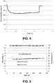
- FIG. 4 shows the current measured with the comparative membrane as a function of time at a fixed cell voltage of 3 V.
- the membrane shows good performance initially, with a current of almost 300 mA/cm 2 and a selectivity of over 90%, showing that the copolymer is a Helper Membrane. Still, the membrane fails in less than 2 hours.
- FIG. 5 shows the performance of the terpolymer membrane as a function of time.
- the cell was run at a fixed voltage of 3 V for 2 hours, then switched to constant current mode at 200 mA/cm 2 for 250 hours. Notice that the cell with the terpolymer membrane was stable for 250 hours. The selectivity was over 90%.
- the total weight of the vinylbenzyl-R x groups is between 1% and 25% of the total weight of the membrane.
- the total weight of the vinylbenzyl-R x groups is between 1% and 15% of the total weight of the membrane.
- the data in example 5 shows preferably the total weight of the vinylbenzyl-Rs groups is at least 15% of the total weight of the membrane, preferably between 15% and 90% of the total weight of the membrane, most preferably between 25% and 80% of the total weight of the membrane.
Landscapes
- Chemical & Material Sciences (AREA)
- Engineering & Computer Science (AREA)
- Chemical Kinetics & Catalysis (AREA)
- Organic Chemistry (AREA)
- Electrochemistry (AREA)
- Materials Engineering (AREA)
- Manufacturing & Machinery (AREA)
- Metallurgy (AREA)
- Sustainable Development (AREA)
- General Chemical & Material Sciences (AREA)
- Sustainable Energy (AREA)
- Life Sciences & Earth Sciences (AREA)
- Crystallography & Structural Chemistry (AREA)
- Inorganic Chemistry (AREA)
- Medicinal Chemistry (AREA)
- Health & Medical Sciences (AREA)
- Polymers & Plastics (AREA)
- Electrolytic Production Of Non-Metals, Compounds, Apparatuses Therefor (AREA)
- Fuel Cell (AREA)
- Inert Electrodes (AREA)
- Electrodes For Compound Or Non-Metal Manufacture (AREA)
- Conductive Materials (AREA)
Claims (6)
- Membrane polymère conductrice d'anions comprenant un terpolymère de styrène, de vinylbenzyl-Rs et de vinylbenzyl-Rx,
Rs étant un groupe amine cyclique chargé positivement,
Rx étant au moins un constituant sélectionné dans le groupe constitué de CI et OH ;
le poids total des groupes vinylbenzyl-Rs étant entre 15 % et 90 % du poids total de la membrane ; et
le poids total des groupes vinylbenzyl-Rx étant entre 1 % et 25 % du poids total de la membrane. - Membrane polymère selon la revendication 1, ladite membrane ayant une épaisseur comprise entre 10 et 300 micromètres.
- Membrane polymère selon la revendication 1, ladite membrane étant une membrane auxiliaire identifiable par application d'un test consistant à :(1) préparer une cathode comprenant 6 mg/cm2 de nanoparticules d'argent sur une couche de diffusion de gaz en papier de fibre de carbone ;(2) préparer une anode comprenant mg/cm2 de RuO2 sur une couche de diffusion de gaz en papier de fibre de carbone(3) préparer un matériau de test de membrane polymérique ;(4) interposer le matériau de test de membrane entre l'anode et la cathode le côté de la cathode étant celui où sont disposées les nanoparticules d'argent en regard d'un côté de la membrane et le côté de l'anode sur lequel est disposé du RuO2 faisant face à l'autre côté de la membrane, formant ainsi un assemblage membrane-électrode ;(5) installer l'assemblage membrane-électrode dans un assemblage matériel de pile à combustible ;(6) diriger un flux de CO2 humidifié à 50°C dans les canaux d'écoulement de produit de départ de cathode tandis que l'assemblage matériau de pile à combustible est à la température et à la pression atmosphérique ambiantes, les canaux d'écoulement de produit de départ d'anode restant ouverts à l'atmosphère à température et pression ambiantes ;(7) appliquer une tension de cellule de 3,0 V par l'intermédiaire d'une connexion électrique entre l'anode et la cathode ;(8) mesurer le courant dans toute la cellule et la concentration de CO et H2 à la sortie du canal d'écoulement de cathode ;(9) calculer la sélectivité de CO comme suit :
 (10) identifier la membrane en tant que membrane auxiliaire si la densité de courant moyen au niveau de la membrane est au moins 20 mA/cm2, le cm2 étant mesuré comme la zone de la couche de diffusion de gaz de cathode qui est recouverte par des particules de catalyseur, et la sélectivité de CO étant au moins 50 % à une tension de cellule de 3,0 V.
 - Membrane polymérique selon la revendication 1, ledit groupe amine cyclique chargé positivement étant un imidazole ou une pyridine.
- Membrane polymérique selon la revendication 4, ledit groupe amine cyclique chargé positivement étant une alkylpyridine.
- Membrane polymérique selon la revendication 4, ledit groupe amine cyclique chargé positivement étant tétraméthylimidazole.
Applications Claiming Priority (3)
| Application Number | Priority Date | Filing Date | Title |
|---|---|---|---|
| US15/090,477 US9580824B2 (en) | 2010-07-04 | 2016-04-04 | Ion-conducting membranes |
| US15/400,775 US9849450B2 (en) | 2010-07-04 | 2017-01-06 | Ion-conducting membranes |
| PCT/US2017/025628 WO2017176599A1 (fr) | 2016-04-04 | 2017-03-31 | Membrane conductrice d'ions |
Publications (2)
| Publication Number | Publication Date |
|---|---|
| EP3440239A1 EP3440239A1 (fr) | 2019-02-13 |
| EP3440239B1 true EP3440239B1 (fr) | 2020-11-18 |
Family
ID=60000636
Family Applications (1)
| Application Number | Title | Priority Date | Filing Date |
|---|---|---|---|
| EP17720603.4A Active EP3440239B1 (fr) | 2016-04-04 | 2017-03-31 | Membrane conductrice d'ions |
Country Status (6)
| Country | Link |
|---|---|
| EP (1) | EP3440239B1 (fr) |
| JP (1) | JP6585859B2 (fr) |
| KR (1) | KR102216963B1 (fr) |
| CN (1) | CN108884579B (fr) |
| AU (1) | AU2017246207B2 (fr) |
| WO (1) | WO2017176599A1 (fr) |
Cited By (3)
| Publication number | Priority date | Publication date | Assignee | Title |
|---|---|---|---|---|
| EP4339231A1 (fr) * | 2022-09-15 | 2024-03-20 | Xerox Corporation | Films organiques structurés contenant de l'imidazolium ayant une fonctionnalité de charge cationique et procédés associés |
| US12202788B2 (en) | 2022-09-15 | 2025-01-21 | Xerox Corporation | Gradient membranes formed from free standing structured organic films and methods thereof |
| US12623212B2 (en) * | 2023-08-02 | 2026-05-12 | Xerox Corporation | Physically reinforced structured organic film (SOF) anion exchange membranes (AEMs) |
Families Citing this family (8)
| Publication number | Priority date | Publication date | Assignee | Title |
|---|---|---|---|---|
| US10147974B2 (en) * | 2017-05-01 | 2018-12-04 | Dioxide Materials, Inc | Battery separator membrane and battery employing same |
| GB2576592B (en) * | 2018-04-17 | 2023-04-19 | Ffi Ionix Ip Inc | Electrolysis cell assembly utilizing an anion exchange membrane |
| GB201810534D0 (en) | 2018-06-27 | 2018-08-15 | Univ Oxford Innovation Ltd | Hydrogen production |
| CN111725549B (zh) * | 2020-06-24 | 2021-05-25 | 常州大学 | 一种基于聚乙烯醇的聚合物电解质膜及其制备方法 |
| JP7527717B2 (ja) * | 2021-06-01 | 2024-08-05 | エルジー エナジー ソリューション リミテッド | 全固体リチウム二次電池およびその製造方法 |
| AU2022425341A1 (en) * | 2021-12-27 | 2024-06-27 | Electric Hydrogen Co. | Multi-layered membranes for electrochemical cells |
| JP7822480B2 (ja) * | 2022-08-22 | 2026-03-02 | 三井化学株式会社 | 陰イオン交換型高分子電解質膜、水電解装置、二酸化炭素電解装置、燃料電池及び陰イオン交換型高分子電解質膜の製造方法 |
| DK181809B1 (en) * | 2023-05-31 | 2025-01-21 | Stiesdal Hydrogen As | Porous membrane, its method of production, and an alkaline electrolyzer with such membrane |
Family Cites Families (55)
| Publication number | Priority date | Publication date | Assignee | Title |
|---|---|---|---|---|
| US3959094A (en) | 1975-03-13 | 1976-05-25 | The United States Of America As Represented By The United States Energy Research And Development Administration | Electrolytic synthesis of methanol from CO2 |
| US4430445A (en) | 1979-07-19 | 1984-02-07 | Asahi Kasei Kogyo Kabushiki Kaisha | Novel basic imidazolylmethylstyrene compound, its polymer, a process for the preparation thereof and a use as ion exchange resin |
| US4240882A (en) | 1979-11-08 | 1980-12-23 | Institute Of Gas Technology | Gas fixation solar cell using gas diffusion semiconductor electrode |
| AU535073B2 (en) | 1979-12-17 | 1984-03-01 | Unisearch Limited | Methanol synthesis catalyst and use thereof |
| US4609451A (en) | 1984-03-27 | 1986-09-02 | Texaco Inc. | Means for reducing carbon dioxide to provide a product |
| US4545872A (en) | 1984-03-27 | 1985-10-08 | Texaco Inc. | Method for reducing carbon dioxide to provide a product |
| US4523981A (en) | 1984-03-27 | 1985-06-18 | Texaco Inc. | Means and method for reducing carbon dioxide to provide a product |
| US4595465A (en) | 1984-12-24 | 1986-06-17 | Texaco Inc. | Means and method for reducing carbn dioxide to provide an oxalate product |
| US4620906A (en) | 1985-01-31 | 1986-11-04 | Texaco Inc. | Means and method for reducing carbon dioxide to provide formic acid |
| US4608132A (en) | 1985-06-06 | 1986-08-26 | Texaco Inc. | Means and method for the electrochemical reduction of carbon dioxide to provide a product |
| US4673473A (en) | 1985-06-06 | 1987-06-16 | Peter G. Pa Ang | Means and method for reducing carbon dioxide to a product |
| US4608133A (en) | 1985-06-10 | 1986-08-26 | Texaco Inc. | Means and method for the electrochemical reduction of carbon dioxide to provide a product |
| US4609441A (en) | 1985-12-18 | 1986-09-02 | Gas Research Institute | Electrochemical reduction of aqueous carbon dioxide to methanol |
| US4609440A (en) | 1985-12-18 | 1986-09-02 | Gas Research Institute | Electrochemical synthesis of methane |
| US4756807A (en) | 1986-10-09 | 1988-07-12 | Gas Research Institute | Chemically modified electrodes for the catalytic reduction of CO2 |
| US4711708A (en) | 1986-10-09 | 1987-12-08 | Gas Research Institute | Chemically modified electrodes for the catalytic reduction of CO2 |
| US4668349A (en) | 1986-10-24 | 1987-05-26 | The Standard Oil Company | Acid promoted electrocatalytic reduction of carbon dioxide by square planar transition metal complexes |
| US4818353A (en) | 1987-07-07 | 1989-04-04 | Langer Stanley H | Method for modifying electrocatalyst material, electrochemical cells and electrodes containing this modified material, and synthesis methods utilizing the cells |
| US5064733A (en) | 1989-09-27 | 1991-11-12 | Gas Research Institute | Electrochemical conversion of CO2 and CH4 to C2 hydrocarbons in a single cell |
| JP3009703B2 (ja) | 1990-05-02 | 2000-02-14 | 正道 藤平 | 二酸化炭素ガス還元用電極触媒 |
| JP3360850B2 (ja) | 1992-09-21 | 2003-01-07 | 株式会社日立製作所 | 銅系酸化触媒とその用途 |
| KR0169188B1 (ko) | 1995-07-31 | 1999-03-20 | 강박광 | 탄화수소의 제조방법 |
| US5709789A (en) | 1996-10-23 | 1998-01-20 | Sachem, Inc. | Electrochemical conversion of nitrogen containing gas to hydroxylamine and hydroxylammonium salts |
| US6660680B1 (en) | 1997-02-24 | 2003-12-09 | Superior Micropowders, Llc | Electrocatalyst powders, methods for producing powders and devices fabricated from same |
| US5928806A (en) | 1997-05-07 | 1999-07-27 | Olah; George A. | Recycling of carbon dioxide into methyl alcohol and related oxygenates for hydrocarbons |
| US6024855A (en) | 1997-08-15 | 2000-02-15 | Sachem, Inc. | Electrosynthesis of hydroxylammonium salts and hydroxylamine using a mediator |
| KR100351625B1 (ko) | 1999-11-11 | 2002-09-11 | 한국화학연구원 | 탄화수소 제조용 촉매 |
| JP4371601B2 (ja) * | 2001-04-11 | 2009-11-25 | 株式会社トクヤマ | バイポーラ膜 |
| US6664207B2 (en) | 2001-09-26 | 2003-12-16 | Conocophillips Company | Catalyst for converting carbon dioxide to oxygenates and processes therefor and therewith |
| US7479570B2 (en) | 2003-09-17 | 2009-01-20 | Japan Science And Technology Agency | Process for reduction of carbon dioxide with organometallic complex |
| US6987134B1 (en) | 2004-07-01 | 2006-01-17 | Robert Gagnon | How to convert carbon dioxide into synthetic hydrocarbon through a process of catalytic hydrogenation called CO2hydrocarbonation |
| WO2006026064A2 (fr) | 2004-08-05 | 2006-03-09 | University Of Wyoming | Nouveaux liquides ioniques et liquides polyioniques utilises en tant que nouveaux materiaux pour separer des gaz et servant egalement dans d'autres applications |
| CA2625656C (fr) | 2005-10-13 | 2014-12-09 | Mantra Energy Alternatives Ltd. | Reduction electrochimique continue du dioxyde de carbone |
| JP4983150B2 (ja) | 2006-04-28 | 2012-07-25 | 東洋インキScホールディングス株式会社 | 導電性被膜の製造方法 |
| US7378561B2 (en) | 2006-08-10 | 2008-05-27 | University Of Southern California | Method for producing methanol, dimethyl ether, derived synthetic hydrocarbons and their products from carbon dioxide and water (moisture) of the air as sole source material |
| EP2150637A1 (fr) | 2007-05-04 | 2010-02-10 | Principle Energy Solutions, Inc. | Production d'hydrocarbures à partir de sources de carbone et d'hydrogène |
| AU2008276180B2 (en) | 2007-07-13 | 2011-08-04 | University Of Southern California | Electrolysis of carbon dioxide in aqueous media to carbon monoxide and hydrogen for production of methanol |
| KR20110038691A (ko) | 2008-07-16 | 2011-04-14 | 칼레라 코포레이션 | 전기화학 시스템에서 co2를 사용하는 방법 |
| CA2749136A1 (fr) | 2009-01-29 | 2010-08-05 | Princeton University | Transformation du dioxyde de carbone en produits organiques |
| WO2011046661A1 (fr) | 2009-07-24 | 2011-04-21 | The Regents Of The University Of Colorado, A Body Corporate | Liquides ioniques à température ambiante, à base d'imidazolium, polymères monomères et membranes les incorporant |
| US8500987B2 (en) | 2010-03-19 | 2013-08-06 | Liquid Light, Inc. | Purification of carbon dioxide from a mixture of gases |
| US8721866B2 (en) | 2010-03-19 | 2014-05-13 | Liquid Light, Inc. | Electrochemical production of synthesis gas from carbon dioxide |
| US20110237830A1 (en) * | 2010-03-26 | 2011-09-29 | Dioxide Materials Inc | Novel catalyst mixtures |
| WO2016064440A1 (fr) * | 2014-10-21 | 2016-04-28 | Dioxide Materials | Électrolyseur et membranes |
| US8552130B2 (en) | 2010-05-18 | 2013-10-08 | 3M Innovative Properties Company | Polymerizable ionic liquid comprising aromatic carboxylate anion |
| US8524066B2 (en) | 2010-07-29 | 2013-09-03 | Liquid Light, Inc. | Electrochemical production of urea from NOx and carbon dioxide |
| WO2012046362A1 (fr) | 2010-10-06 | 2012-04-12 | パナソニック株式会社 | Procédé de réduction du dioxyde de carbone |
| US8568581B2 (en) | 2010-11-30 | 2013-10-29 | Liquid Light, Inc. | Heterocycle catalyzed carbonylation and hydroformylation with carbon dioxide |
| US20120171583A1 (en) | 2010-12-30 | 2012-07-05 | Liquid Light, Inc. | Gas phase electrochemical reduction of carbon dioxide |
| US8414758B2 (en) | 2011-03-09 | 2013-04-09 | Panasonic Corporation | Method for reducing carbon dioxide |
| US8562811B2 (en) | 2011-03-09 | 2013-10-22 | Liquid Light, Inc. | Process for making formic acid |
| JP2014518335A (ja) | 2011-07-06 | 2014-07-28 | リキッド・ライト・インコーポレーテッド | 二酸化炭素のカルボン酸、グリコール、及びカルボキシレートへの還元 |
| AU2012278948A1 (en) | 2011-07-06 | 2014-01-16 | Liquid Light, Inc. | Carbon dioxide capture and conversion to organic products |
| US20130105304A1 (en) * | 2012-07-26 | 2013-05-02 | Liquid Light, Inc. | System and High Surface Area Electrodes for the Electrochemical Reduction of Carbon Dioxide |
| JP6606182B2 (ja) * | 2014-09-08 | 2019-11-13 | スリーエム イノベイティブ プロパティズ カンパニー | 二酸化炭素電気分解装置用のイオン性ポリマー膜 |
-
2017
- 2017-03-31 KR KR1020187031597A patent/KR102216963B1/ko active Active
- 2017-03-31 EP EP17720603.4A patent/EP3440239B1/fr active Active
- 2017-03-31 JP JP2018551973A patent/JP6585859B2/ja active Active
- 2017-03-31 CN CN201780021657.8A patent/CN108884579B/zh not_active Expired - Fee Related
- 2017-03-31 WO PCT/US2017/025628 patent/WO2017176599A1/fr not_active Ceased
- 2017-03-31 AU AU2017246207A patent/AU2017246207B2/en active Active
Non-Patent Citations (1)
| Title |
|---|
| None * |
Cited By (3)
| Publication number | Priority date | Publication date | Assignee | Title |
|---|---|---|---|---|
| EP4339231A1 (fr) * | 2022-09-15 | 2024-03-20 | Xerox Corporation | Films organiques structurés contenant de l'imidazolium ayant une fonctionnalité de charge cationique et procédés associés |
| US12202788B2 (en) | 2022-09-15 | 2025-01-21 | Xerox Corporation | Gradient membranes formed from free standing structured organic films and methods thereof |
| US12623212B2 (en) * | 2023-08-02 | 2026-05-12 | Xerox Corporation | Physically reinforced structured organic film (SOF) anion exchange membranes (AEMs) |
Also Published As
| Publication number | Publication date |
|---|---|
| JP2019519668A (ja) | 2019-07-11 |
| AU2017246207B2 (en) | 2019-03-07 |
| CN108884579B (zh) | 2019-08-16 |
| EP3440239A1 (fr) | 2019-02-13 |
| KR20180132774A (ko) | 2018-12-12 |
| CN108884579A (zh) | 2018-11-23 |
| WO2017176599A1 (fr) | 2017-10-12 |
| AU2017246207A1 (en) | 2018-11-01 |
| KR102216963B1 (ko) | 2021-02-19 |
| JP6585859B2 (ja) | 2019-10-02 |
Similar Documents
| Publication | Publication Date | Title |
|---|---|---|
| US9849450B2 (en) | Ion-conducting membranes | |
| US9580824B2 (en) | Ion-conducting membranes | |
| US9370773B2 (en) | Ion-conducting membranes | |
| AU2017246207B2 (en) | Ion-conducting membranes | |
| US10047446B2 (en) | Method and system for electrochemical production of formic acid from carbon dioxide | |
| US10774431B2 (en) | Ion-conducting membranes | |
| US10428432B2 (en) | Catalyst layers and electrolyzers | |
| KR102291918B1 (ko) | 촉매 층 및 전해장치 | |
| KR20180126573A (ko) | 수 전해장치 | |
| Masel et al. | Ion-conducting membranes | |
| Masel et al. | Electrochemical device for converting carbon dioxide to a reaction product |
Legal Events
| Date | Code | Title | Description |
|---|---|---|---|
| STAA | Information on the status of an ep patent application or granted ep patent |
Free format text: STATUS: UNKNOWN |
|
| STAA | Information on the status of an ep patent application or granted ep patent |
Free format text: STATUS: THE INTERNATIONAL PUBLICATION HAS BEEN MADE |
|
| PUAI | Public reference made under article 153(3) epc to a published international application that has entered the european phase |
Free format text: ORIGINAL CODE: 0009012 |
|
| STAA | Information on the status of an ep patent application or granted ep patent |
Free format text: STATUS: REQUEST FOR EXAMINATION WAS MADE |
|
| 17P | Request for examination filed |
Effective date: 20181022 |
|
| AK | Designated contracting states |
Kind code of ref document: A1 Designated state(s): AL AT BE BG CH CY CZ DE DK EE ES FI FR GB GR HR HU IE IS IT LI LT LU LV MC MK MT NL NO PL PT RO RS SE SI SK SM TR |
|
| AX | Request for extension of the european patent |
Extension state: BA ME |
|
| RIN1 | Information on inventor provided before grant (corrected) |
Inventor name: CHEN, QINGMEI Inventor name: GAO, YAN Inventor name: MASEL, RICHARD I. Inventor name: SAJJAD, SYED DAWAR Inventor name: LIU, ZENGCAI |
|
| RIN1 | Information on inventor provided before grant (corrected) |
Inventor name: GAO, YAN Inventor name: CHEN, QINGMEI Inventor name: SAJJAD, SYED DAWAR Inventor name: LIU, ZENGCAI Inventor name: MASEL, RICHARD I. |
|
| DAV | Request for validation of the european patent (deleted) | ||
| DAX | Request for extension of the european patent (deleted) | ||
| STAA | Information on the status of an ep patent application or granted ep patent |
Free format text: STATUS: EXAMINATION IS IN PROGRESS |
|
| 17Q | First examination report despatched |
Effective date: 20190913 |
|
| GRAP | Despatch of communication of intention to grant a patent |
Free format text: ORIGINAL CODE: EPIDOSNIGR1 |
|
| STAA | Information on the status of an ep patent application or granted ep patent |
Free format text: STATUS: GRANT OF PATENT IS INTENDED |
|
| INTG | Intention to grant announced |
Effective date: 20200424 |
|
| GRAS | Grant fee paid |
Free format text: ORIGINAL CODE: EPIDOSNIGR3 |
|
| GRAJ | Information related to disapproval of communication of intention to grant by the applicant or resumption of examination proceedings by the epo deleted |
Free format text: ORIGINAL CODE: EPIDOSDIGR1 |
|
| GRAL | Information related to payment of fee for publishing/printing deleted |
Free format text: ORIGINAL CODE: EPIDOSDIGR3 |
|
| STAA | Information on the status of an ep patent application or granted ep patent |
Free format text: STATUS: EXAMINATION IS IN PROGRESS |
|
| INTC | Intention to grant announced (deleted) | ||
| GRAP | Despatch of communication of intention to grant a patent |
Free format text: ORIGINAL CODE: EPIDOSNIGR1 |
|
| STAA | Information on the status of an ep patent application or granted ep patent |
Free format text: STATUS: GRANT OF PATENT IS INTENDED |
|
| GRAA | (expected) grant |
Free format text: ORIGINAL CODE: 0009210 |
|
| STAA | Information on the status of an ep patent application or granted ep patent |
Free format text: STATUS: THE PATENT HAS BEEN GRANTED |
|
| INTG | Intention to grant announced |
Effective date: 20201005 |
|
| AK | Designated contracting states |
Kind code of ref document: B1 Designated state(s): AL AT BE BG CH CY CZ DE DK EE ES FI FR GB GR HR HU IE IS IT LI LT LU LV MC MK MT NL NO PL PT RO RS SE SI SK SM TR |
|
| REG | Reference to a national code |
Ref country code: GB Ref legal event code: FG4D |
|
| REG | Reference to a national code |
Ref country code: DE Ref legal event code: R079 Ref document number: 602017027749 Country of ref document: DE Free format text: PREVIOUS MAIN CLASS: C25B0003040000 Ipc: C25B0003250000 |
|
| REG | Reference to a national code |
Ref country code: CH Ref legal event code: EP |
|
| REG | Reference to a national code |
Ref country code: DE Ref legal event code: R096 Ref document number: 602017027749 Country of ref document: DE |
|
| REG | Reference to a national code |
Ref country code: IE Ref legal event code: FG4D |
|
| REG | Reference to a national code |
Ref country code: AT Ref legal event code: REF Ref document number: 1335884 Country of ref document: AT Kind code of ref document: T Effective date: 20201215 |
|
| REG | Reference to a national code |
Ref country code: AT Ref legal event code: MK05 Ref document number: 1335884 Country of ref document: AT Kind code of ref document: T Effective date: 20201118 |
|
| REG | Reference to a national code |
Ref country code: NL Ref legal event code: MP Effective date: 20201118 |
|
| PG25 | Lapsed in a contracting state [announced via postgrant information from national office to epo] |
Ref country code: PT Free format text: LAPSE BECAUSE OF FAILURE TO SUBMIT A TRANSLATION OF THE DESCRIPTION OR TO PAY THE FEE WITHIN THE PRESCRIBED TIME-LIMIT Effective date: 20210318 Ref country code: RS Free format text: LAPSE BECAUSE OF FAILURE TO SUBMIT A TRANSLATION OF THE DESCRIPTION OR TO PAY THE FEE WITHIN THE PRESCRIBED TIME-LIMIT Effective date: 20201118 Ref country code: NO Free format text: LAPSE BECAUSE OF FAILURE TO SUBMIT A TRANSLATION OF THE DESCRIPTION OR TO PAY THE FEE WITHIN THE PRESCRIBED TIME-LIMIT Effective date: 20210218 Ref country code: FI Free format text: LAPSE BECAUSE OF FAILURE TO SUBMIT A TRANSLATION OF THE DESCRIPTION OR TO PAY THE FEE WITHIN THE PRESCRIBED TIME-LIMIT Effective date: 20201118 Ref country code: GR Free format text: LAPSE BECAUSE OF FAILURE TO SUBMIT A TRANSLATION OF THE DESCRIPTION OR TO PAY THE FEE WITHIN THE PRESCRIBED TIME-LIMIT Effective date: 20210219 |
|
| PG25 | Lapsed in a contracting state [announced via postgrant information from national office to epo] |
Ref country code: LV Free format text: LAPSE BECAUSE OF FAILURE TO SUBMIT A TRANSLATION OF THE DESCRIPTION OR TO PAY THE FEE WITHIN THE PRESCRIBED TIME-LIMIT Effective date: 20201118 Ref country code: IS Free format text: LAPSE BECAUSE OF FAILURE TO SUBMIT A TRANSLATION OF THE DESCRIPTION OR TO PAY THE FEE WITHIN THE PRESCRIBED TIME-LIMIT Effective date: 20210318 Ref country code: PL Free format text: LAPSE BECAUSE OF FAILURE TO SUBMIT A TRANSLATION OF THE DESCRIPTION OR TO PAY THE FEE WITHIN THE PRESCRIBED TIME-LIMIT Effective date: 20201118 Ref country code: BG Free format text: LAPSE BECAUSE OF FAILURE TO SUBMIT A TRANSLATION OF THE DESCRIPTION OR TO PAY THE FEE WITHIN THE PRESCRIBED TIME-LIMIT Effective date: 20210218 Ref country code: AT Free format text: LAPSE BECAUSE OF FAILURE TO SUBMIT A TRANSLATION OF THE DESCRIPTION OR TO PAY THE FEE WITHIN THE PRESCRIBED TIME-LIMIT Effective date: 20201118 Ref country code: SE Free format text: LAPSE BECAUSE OF FAILURE TO SUBMIT A TRANSLATION OF THE DESCRIPTION OR TO PAY THE FEE WITHIN THE PRESCRIBED TIME-LIMIT Effective date: 20201118 |
|
| REG | Reference to a national code |
Ref country code: LT Ref legal event code: MG9D |
|
| PG25 | Lapsed in a contracting state [announced via postgrant information from national office to epo] |
Ref country code: HR Free format text: LAPSE BECAUSE OF FAILURE TO SUBMIT A TRANSLATION OF THE DESCRIPTION OR TO PAY THE FEE WITHIN THE PRESCRIBED TIME-LIMIT Effective date: 20201118 |
|
| PG25 | Lapsed in a contracting state [announced via postgrant information from national office to epo] |
Ref country code: SK Free format text: LAPSE BECAUSE OF FAILURE TO SUBMIT A TRANSLATION OF THE DESCRIPTION OR TO PAY THE FEE WITHIN THE PRESCRIBED TIME-LIMIT Effective date: 20201118 Ref country code: RO Free format text: LAPSE BECAUSE OF FAILURE TO SUBMIT A TRANSLATION OF THE DESCRIPTION OR TO PAY THE FEE WITHIN THE PRESCRIBED TIME-LIMIT Effective date: 20201118 Ref country code: LT Free format text: LAPSE BECAUSE OF FAILURE TO SUBMIT A TRANSLATION OF THE DESCRIPTION OR TO PAY THE FEE WITHIN THE PRESCRIBED TIME-LIMIT Effective date: 20201118 Ref country code: EE Free format text: LAPSE BECAUSE OF FAILURE TO SUBMIT A TRANSLATION OF THE DESCRIPTION OR TO PAY THE FEE WITHIN THE PRESCRIBED TIME-LIMIT Effective date: 20201118 Ref country code: CZ Free format text: LAPSE BECAUSE OF FAILURE TO SUBMIT A TRANSLATION OF THE DESCRIPTION OR TO PAY THE FEE WITHIN THE PRESCRIBED TIME-LIMIT Effective date: 20201118 Ref country code: SM Free format text: LAPSE BECAUSE OF FAILURE TO SUBMIT A TRANSLATION OF THE DESCRIPTION OR TO PAY THE FEE WITHIN THE PRESCRIBED TIME-LIMIT Effective date: 20201118 |
|
| REG | Reference to a national code |
Ref country code: DE Ref legal event code: R097 Ref document number: 602017027749 Country of ref document: DE |
|
| PG25 | Lapsed in a contracting state [announced via postgrant information from national office to epo] |
Ref country code: DK Free format text: LAPSE BECAUSE OF FAILURE TO SUBMIT A TRANSLATION OF THE DESCRIPTION OR TO PAY THE FEE WITHIN THE PRESCRIBED TIME-LIMIT Effective date: 20201118 |
|
| PLBE | No opposition filed within time limit |
Free format text: ORIGINAL CODE: 0009261 |
|
| STAA | Information on the status of an ep patent application or granted ep patent |
Free format text: STATUS: NO OPPOSITION FILED WITHIN TIME LIMIT |
|
| 26N | No opposition filed |
Effective date: 20210819 |
|
| PG25 | Lapsed in a contracting state [announced via postgrant information from national office to epo] |
Ref country code: AL Free format text: LAPSE BECAUSE OF FAILURE TO SUBMIT A TRANSLATION OF THE DESCRIPTION OR TO PAY THE FEE WITHIN THE PRESCRIBED TIME-LIMIT Effective date: 20201118 Ref country code: NL Free format text: LAPSE BECAUSE OF FAILURE TO SUBMIT A TRANSLATION OF THE DESCRIPTION OR TO PAY THE FEE WITHIN THE PRESCRIBED TIME-LIMIT Effective date: 20201118 Ref country code: MC Free format text: LAPSE BECAUSE OF FAILURE TO SUBMIT A TRANSLATION OF THE DESCRIPTION OR TO PAY THE FEE WITHIN THE PRESCRIBED TIME-LIMIT Effective date: 20201118 Ref country code: IT Free format text: LAPSE BECAUSE OF FAILURE TO SUBMIT A TRANSLATION OF THE DESCRIPTION OR TO PAY THE FEE WITHIN THE PRESCRIBED TIME-LIMIT Effective date: 20201118 |
|
| REG | Reference to a national code |
Ref country code: CH Ref legal event code: PL |
|
| PG25 | Lapsed in a contracting state [announced via postgrant information from national office to epo] |
Ref country code: SI Free format text: LAPSE BECAUSE OF FAILURE TO SUBMIT A TRANSLATION OF THE DESCRIPTION OR TO PAY THE FEE WITHIN THE PRESCRIBED TIME-LIMIT Effective date: 20201118 |
|
| REG | Reference to a national code |
Ref country code: BE Ref legal event code: MM Effective date: 20210331 |
|
| PG25 | Lapsed in a contracting state [announced via postgrant information from national office to epo] |
Ref country code: LU Free format text: LAPSE BECAUSE OF NON-PAYMENT OF DUE FEES Effective date: 20210331 Ref country code: LI Free format text: LAPSE BECAUSE OF NON-PAYMENT OF DUE FEES Effective date: 20210331 Ref country code: CH Free format text: LAPSE BECAUSE OF NON-PAYMENT OF DUE FEES Effective date: 20210331 Ref country code: ES Free format text: LAPSE BECAUSE OF FAILURE TO SUBMIT A TRANSLATION OF THE DESCRIPTION OR TO PAY THE FEE WITHIN THE PRESCRIBED TIME-LIMIT Effective date: 20201118 Ref country code: IE Free format text: LAPSE BECAUSE OF NON-PAYMENT OF DUE FEES Effective date: 20210331 |
|
| PG25 | Lapsed in a contracting state [announced via postgrant information from national office to epo] |
Ref country code: IS Free format text: LAPSE BECAUSE OF FAILURE TO SUBMIT A TRANSLATION OF THE DESCRIPTION OR TO PAY THE FEE WITHIN THE PRESCRIBED TIME-LIMIT Effective date: 20210318 |
|
| PG25 | Lapsed in a contracting state [announced via postgrant information from national office to epo] |
Ref country code: BE Free format text: LAPSE BECAUSE OF NON-PAYMENT OF DUE FEES Effective date: 20210331 |
|
| PG25 | Lapsed in a contracting state [announced via postgrant information from national office to epo] |
Ref country code: CY Free format text: LAPSE BECAUSE OF FAILURE TO SUBMIT A TRANSLATION OF THE DESCRIPTION OR TO PAY THE FEE WITHIN THE PRESCRIBED TIME-LIMIT Effective date: 20201118 |
|
| P01 | Opt-out of the competence of the unified patent court (upc) registered |
Effective date: 20230526 |
|
| PG25 | Lapsed in a contracting state [announced via postgrant information from national office to epo] |
Ref country code: HU Free format text: LAPSE BECAUSE OF FAILURE TO SUBMIT A TRANSLATION OF THE DESCRIPTION OR TO PAY THE FEE WITHIN THE PRESCRIBED TIME-LIMIT; INVALID AB INITIO Effective date: 20170331 |
|
| PG25 | Lapsed in a contracting state [announced via postgrant information from national office to epo] |
Ref country code: MK Free format text: LAPSE BECAUSE OF FAILURE TO SUBMIT A TRANSLATION OF THE DESCRIPTION OR TO PAY THE FEE WITHIN THE PRESCRIBED TIME-LIMIT Effective date: 20201118 |
|
| PG25 | Lapsed in a contracting state [announced via postgrant information from national office to epo] |
Ref country code: TR Free format text: LAPSE BECAUSE OF FAILURE TO SUBMIT A TRANSLATION OF THE DESCRIPTION OR TO PAY THE FEE WITHIN THE PRESCRIBED TIME-LIMIT Effective date: 20201118 |
|
| PG25 | Lapsed in a contracting state [announced via postgrant information from national office to epo] |
Ref country code: MT Free format text: LAPSE BECAUSE OF FAILURE TO SUBMIT A TRANSLATION OF THE DESCRIPTION OR TO PAY THE FEE WITHIN THE PRESCRIBED TIME-LIMIT Effective date: 20201118 |
|
| PGFP | Annual fee paid to national office [announced via postgrant information from national office to epo] |
Ref country code: GB Payment date: 20260327 Year of fee payment: 10 |
|
| PGFP | Annual fee paid to national office [announced via postgrant information from national office to epo] |
Ref country code: DE Payment date: 20260327 Year of fee payment: 10 |
|
| PGFP | Annual fee paid to national office [announced via postgrant information from national office to epo] |
Ref country code: FR Payment date: 20260325 Year of fee payment: 10 |