EP3440247B1 - Module de formation de foule pour dispositif de tissage - Google Patents
Module de formation de foule pour dispositif de tissage Download PDFInfo
- Publication number
- EP3440247B1 EP3440247B1 EP17722875.6A EP17722875A EP3440247B1 EP 3440247 B1 EP3440247 B1 EP 3440247B1 EP 17722875 A EP17722875 A EP 17722875A EP 3440247 B1 EP3440247 B1 EP 3440247B1
- Authority
- EP
- European Patent Office
- Prior art keywords
- shed
- oscillating
- bar
- lever
- forming module
- Prior art date
- Legal status (The legal status is an assumption and is not a legal conclusion. Google has not performed a legal analysis and makes no representation as to the accuracy of the status listed.)
- Active
Links
Images


Classifications
-
- D—TEXTILES; PAPER
- D03—WEAVING
- D03C—SHEDDING MECHANISMS; PATTERN CARDS OR CHAINS; PUNCHING OF CARDS; DESIGNING PATTERNS
- D03C3/00—Jacquards
- D03C3/24—Features common to jacquards of different types
- D03C3/32—Jacquard driving mechanisms
- D03C3/36—Griffe operating mechanisms
Definitions
- the invention relates to a shed-forming module for the selective movement of shed-forming elements using lifting elements, wherein several shed-forming elements, in projection onto a plane perpendicular to their movement direction, are situated next to each other in a first direction and in a second direction perpendicular to the first direction, wherein the shed-forming module comprises the components as described in the preamble of the first claim.
- a shed-forming module is used more particularly in open-shed jacquard machines with two or more positions.
- the invention furthermore relates to a weaving machine provided with such a shed-forming module or a jacquard machine provided with such a shed-forming module.
- the warp threads are positioned during the successive weaving cycles with respect to the level at which a weft thread is introduced in each cycle.
- the positions of the warp threads in the successive weaving cycles are in this case determined in such a manner that the weaving process results in a fabric with a predetermined weaving pattern.
- This positioning of the warp threads with respect to the weft insertion level on a weaving machine, known as shed forming, is realized automatically by means of a shed-forming device or shed-forming module.
- the known shed-forming device comprises one or more selection systems which are provided to select or not select one or more hooks.
- a hook is selectively carried or not carried by a lifting element which is movable in the vertical direction and forms part of a set of lifting elements consisting of at least two lifting elements which move up and down in pairs in antiphase.
- These lifting elements are driven in an up and down movement in antiphase with respect to each other, according to an adjustable amplitude, via lifting means such as for example knife grids.
- a shed-forming device comprises at least two sets of knife grids moving up and down, for example on two opposite sides of the shed-forming device.
- European patent application EP 1 705 272 in the name of the present applicant describes a jacquard device as shown in figure 1 , comprising, on two opposing sides of the jacquard device, at least two sets of knife grids moving up and down in antiphase.
- At least one drive lever is provided which is driven by a single sided drive.
- a continuous, oscillating shaft is provided which transfers the movement of the drive lever.
- the device comprises two oscillating levers (41a, 41b; 42a, 42b) placed next to each other (viewed in the warp direction).
- German patent publication DE 25 07 486 describes a shed-forming module with several lifting elements which are movable up and down, wherein each lifting element is driven separately.
- the movement amplitude of the lifting elements in this system can be set separately for each lifting element, whereby changing the movement amplitude for all lifting elements is a very time-consuming activity.
- the object of this invention is therefore to provide a shed-forming module which allows the movement amplitude to be adjusted more easily and unambiguously.
- the object of the invention is achieved by providing a shed-forming module for the selective movement of shed-forming elements using lifting elements, wherein several shed-forming elements, when projected onto a plane perpendicular to their movement direction, are located next to each other in a first direction and in a second direction perpendicular to the first direction, and comprising:
- Such a shed-forming module has the great advantage that the size of the movement amplitude of the lifting elements can be adjusted completely by the drive mechanism, so that without too much time loss, this amplitude of the lifting elements can be adjusted without generating undesirable movement deviations and/or movement differences.
- the first direction may be the direction which corresponds to the weft direction or the direction which corresponds to the warp direction.
- the first direction is the weft direction and the second direction is the warp direction.
- the drive mechanism comprises at least two adjustment means which are each connected to a different transfer mechanism and which are each provided to adjust the movement amplitude of the associated transfer mechanism independently, and which together determine the movement amplitude of all shed-forming elements such that the movement amplitude of all shed-forming elements in the first direction is the same, and the movement amplitude of all shed-forming elements changes linearly in the second direction.
- the drive mechanism comprises a first and a second adjustment means which are intended to be coupled respectively to the first and second transfer mechanism. Via these two adjustment means, the movement amplitude of the entire shed-forming module can be adjusted. In particular, the movement amplitude of each oscillating lever is unambiguously determined by the movement amplitude of the connected transfer mechanism.
- the drive mechanism comprises a first and a second driveable and adjustable four-bar mechanism, wherein the first four-bar mechanism is provided for driving an oscillating lever of the first transfer mechanism and the second four-bar mechanism is provided for driving an oscillating lever of the second transfer mechanism.
- the drive mechanism comprises a main drive shaft, wherein the first and second four-bar mechanisms are mechanically coupled to this main drive shaft.
- each four-bar mechanism comprises an adjustment means.
- the first four-bar mechanism is provided with a first adjustment means
- the second four-bar mechanism is provided with a second adjustment means.
- the adjustment means is configured as a bar of the four-bar mechanism with a slot in which another bar of the respective four-bar mechanism is displaceable for adjusting the amplitude
- the adjustment means is configured as a bar of the four-bar mechanism with a number of different coupling points to which another bar of the four-bar mechanism can be coupled for adjusting the amplitude.
- the shed-forming module on two opposing sides of the module in the first direction, comprises two lifting means which are movable up and down in antiphase for moving the lifting elements up and down, and each oscillating lever is connected to these lifting means via two connecting rods which are movable up and down in antiphase.
- each oscillating lever comprises a first and second lever arm which are each intended to be connected to the one end of one of the two connecting rods.
- the lifting means preferably knife grids, are provided at each side of the shed-forming module so that, on both left and right (viewed from the point of view of the weaver looking in the direction of the warp yarn supplied) in the shed-forming module, two knife grids are present moving up and down in antiphase.
- the first transfer mechanism comprises a first and second oscillating lever
- the second transfer mechanism comprises a third and fourth oscillating lever
- the first and third oscillating levers are provided for moving the lifting means up and down in antiphase on one side of the module
- the second and fourth oscillating levers are provided for moving the lifting means up and down in antiphase on the other side of the module
- the first four-bar mechanism is provided for driving the first oscillating lever via a first drive rod
- the second four-bar mechanism is provided for driving the third oscillating lever via a second drive rod.
- the connecting mechanism of the first transfer mechanism comprises a second lever arm of a fifth oscillating lever and a second lever arm of a sixth oscillating lever, connected respectively to the first and second oscillating lever and which are connected together via a connecting rod
- the connecting mechanism of the second transfer mechanism comprises a second lever arm of a seventh oscillating lever and a second lever arm of an eighth oscillating lever, connected respectively to the third and fourth oscillating lever and which are connected together via a connecting rod.
- the fifth, sixth, seventh and eighth oscillating levers are each composed of a first and second lever arm.
- the first four-bar mechanism is formed by the first adjustment means, the first drive rod and the first lever arm of the fifth oscillating lever
- the second four-bar mechanism is formed by the second adjustment means, the second drive rod and the first lever arm of the seventh oscillating lever.
- first lever arm of the fifth oscillating lever forms part of the first four-bar mechanism
- second lever arm of the fifth oscillating lever forms part of the connecting mechanism of the first transfer mechanism
- the first lever arm of the seventh oscillating lever forms part of the second four-bar mechanism
- the second lever arm of the seventh oscillating lever forms part of the connecting mechanism of the second transfer mechanism. Both four-bar mechanisms form part of the drive mechanism.
- the first and second four-bar mechanisms respectively drive a first and a second oscillatable shaft.
- the oscillatable shaft is subdivided into two parts. A first part is connected to the first or second four-bar mechanism and is intended to impose the movement. This part forms part of the drive mechanism.
- the oscillatable shaft has a second part which extends at the shed-forming elements. The second part forms part of the connecting mechanism which connects together the oscillating levers per transfer mechanism, and in this function forms part of the transfer mechanism.
- each oscillatable shaft comprises a number of oscillating levers placed next to each other, and each oscillating lever is connected directly or indirectly to the lifting elements via two connecting rods which are movable up and down in antiphase.
- the lifting elements are preferably knives.
- the jacquard machine is preferably an open-shed jacquard machine with two or more positions.
- This invention furthermore relates to a weaving machine provided with a shed-forming module according to the invention as described above.
- the weaving machine preferably comprises a jacquard machine according to the invention.
- the shed-forming module (1) is configured for selective movement of shed-forming elements using lifting elements, preferably in the form of knives.
- the shed-forming elements when projected onto a plane perpendicular to their movement direction, are located next to each other in a first direction and in a second direction perpendicular to the first direction.
- the first direction is the weft direction and the second direction is the warp direction.
- the first direction may be the warp direction and the second direction the weft direction.
- the shed-forming module (1) according to this invention comprises:
- the drive mechanism (16) does not form part of the transfer mechanism (12, 13).
- the innovative feature of the shed-forming module (1) according to the invention is that the lifting elements through the first (12) and second (13) transfer mechanisms are coupled to the drive mechanism (16) in such a manner that the movement profile and movement amplitude of the lifting elements are fully adjustable via the drive mechanism (16).
- the movement amplitude of the two transfer mechanisms (12, 13) can be set via an adjustment means (17, 18) which forms part of the drive mechanism (16).
- the drive mechanism (16) consequently comprises at least two adjustment means (17, 18). Via the adjustment means (17, 18), it is possible to set the movement amplitude of the associated transfer mechanism independently.
- the two adjustment means (17, 18) together determine the movement amplitude of all shed-forming elements, such that the movement amplitude of all shed-forming elements in the first direction is the same, and the movement amplitude of all shed-forming elements changes linearly in the second direction. Via these two adjustment means (17, 18), the movement amplitude of the entire shed-forming module can be set.
- the lifting elements (26) are moved up and down in antiphase via two lifting means (2, 3) which are movable up and down in antiphase and which in the present embodiment are configured in the form of knife grids located on two opposing sides of the module (1), on the left and right viewed from the point of view of the weaver looking in the direction of the supplied warp yarn.
- each oscillating lever (4, 5; 6, 7) is connected to the lifting means (2, 3) via two connecting rods (19) which are movable up and down in antiphase.
- each oscillating lever (4, 5; 6, 7) comprises a first (4a, 5a, 6a, 7a) and a second (4b, 5b, 6b, 7b) lever arm, each of which is intended to be connected to the one end of one of the two connecting rods (19).
- the first transfer mechanism (12) is located on the front of the module (1) (viewed from the point of view of the weaver looking in the direction of the supplied warp yarn) and comprises a first (4) and a second (5) oscillating lever.
- the second transfer mechanism (13) is located on the back of the module (1) and comprises a third (6) and a fourth (7) oscillating lever.
- the first (4) and third (6) oscillating levers are provided for moving the lifting means (2, 3) up and down in antiphase on the right side of the module (1)
- the second (5) and fourth (7) oscillating levers are provided for moving the lifting means (2, 3) up and down in antiphase on the left side of the module (1).
- the drive mechanism (16) used in this invention comprises a first and a second driveable and adjustable four-bar mechanism, wherein the first four-bar mechanism is provided for driving an oscillating lever of the first transfer mechanism (12), and the second four-bar mechanism is provided for driving an oscillating lever of the second transfer mechanism (13).
- the drive mechanism furthermore comprises a main drive shaft, wherein the first and the second four-bar mechanisms are mechanically coupled to this main drive shaft.
- the first four-bar mechanism is connected to the first oscillating lever (4) and the second four-bar mechanism is connected to the third oscillating lever (6). Because the first oscillating lever (4) is connected to one end of the lifting means (2, 3) which are installed on the one side, e.g. the right-hand side (viewed from the point of view of the weaver looking in the direction of the supplied warp yarn) of the module (1), and because the third oscillating lever (6) is connected to the other end of the same lifting means (2, 3), the two four-bar mechanisms are responsible for driving the movement of these lifting means.
- the size of the movement amplitude of the lifting elements is completely set by the drive mechanism (16), so that without losing too much time, the amplitude of the lifting elements can be adapted without generating undesirable movement deviations and/or movement differences.
- the shed-forming module (1) depicted in figure 2 comprises, on two opposite sides of the module (1), on the left and right viewed from the point of view of the weaver looking in the direction of the supplied warp yarn, two lifting means (2, 3) in the form of knife grids which are movable up and down in antiphase.
- two lifting means (2, 3) in the form of knife grids which are movable up and down in antiphase.
- a respective driveable and adjustable four-bar mechanism is used to drive the movement of these knife grids (2, 3) on the front and back of the module (1), viewed from the point of view of the weaver looking in the direction of the supplied warp yarn.
- the four-bar mechanism is here formed on the front by: the first adjustment means (17), a first drive rod (20) and a first lever arm (8a), connected to the first oscillating lever (4) and belonging to a fifth oscillating lever (8), while the four-bar mechanism located on the back is formed by the second adjustment means (18), a second drive rod (21) and a first lever arm (10a), connected to the third oscillating lever (6) and belonging to a seventh oscillating lever (10).
- Both the fifth (8) and the seventh (10) oscillating levers are composed of a first (8a, 10a) and a second (8b, 10b) lever arm.
- the first (17, 20, 8a) and the second (18, 21, 10a) four-bar mechanisms initiate the movement; they are coupled mechanically at one end to a main drive shaft which is driven by a motor.
- the mechanical coupling takes place via an element (17, 18) which is provided with a slot in which the drive rod (20, 21) is held.
- an element (17, 18) which is provided with a slot in which the drive rod (20, 21) is held.
- separate coupling points may be provided to which the drive rod (20, 21) may be coupled.
- These two elements form the first and second adjustment means (17, 18).
- the amplitude can be changed by changing the position of the drive rod (20, 21) in the slot, or by fixing the drive rod (20, 21) to another coupling point (23) on the element (17, 18) concerned.
- the two four-bar mechanisms stand via their other end in connection with the first (4) and third (6) oscillating levers respectively.
- the connecting mechanism (14) of the first transfer mechanism (12) comprises a second lever arm (8b) connected to the first oscillating lever (4) and belonging to the fifth oscillating lever (8)
- the connecting mechanism (15) of the second transfer mechanism (13) comprises a second lever arm (10b) connected to the third oscillating lever (6) and belonging to the seventh oscillating lever (10).
- the first oscillating lever (4), the first lever arm (8a) of the fifth oscillating lever (8) and the second lever arm (8b) of the fifth oscillating lever (8) may be separate components which are rigidly coupled together. They may also be formed integrally as one piece, as shown in figure 2 .
- the third oscillating lever (6), the first lever arm (10a) of the seventh oscillating lever (10) and the second lever arm (10b) of the seventh oscillating lever (10) are preferably produced in the same way: as separate components which are rigidly connected together, or as one piece.
- the first four-bar mechanism is connected to the second lever arm (8b) of the fifth oscillating lever (8), and the second four-bar mechanism is connected to the second lever arm (10b) of the seventh oscillating lever (10).
- the second lever arm (8b) of the fifth oscillating lever (8), and the second lever arm (10b) of the seventh oscillating lever (10) are connected via a connecting rod (22) respectively to the second lever arm (9b) of the sixth oscillating lever (9) and the second lever arm of the eighth oscillating lever (11).
- the sixth oscillating lever (9) forms part of the connecting mechanism (14) of the first transfer mechanism (12)
- the eighth oscillating lever (11) forms part of the connecting mechanism (15) of the second transfer mechanism (13).
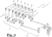
- the embodiment of the shed-forming module (1) according to the invention shown in figure 3 also uses the four-bar mechanism described above. The difference however is that the lifting elements (26) (knives) are rotated through 90° relative to the structure of the lifting elements used in figure 2 . As a result, there are no knife grids, but the lifting elements (26) are connected directly via the connecting rods to the oscillating levers of the transfer mechanisms (12, 13).
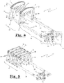
- the shed-forming module (1) is presented in figures 4 and 5 .
- the shed-forming module (1) depicted in figure 4 on its two opposing sides of the module (1), on the left and right viewed from the point of view of the weaver looking in the direction of the supplied warp yarn, comprises two lifting means (2, 3) which are movable up and down in antiphase, in the form of knife grids.
- the respective oscillatable shafts (24, 25) are used which are connected via an oscillating element and connecting rods (19) to the ends of the knife grids (2, 3).
- the oscillatable shafts (24, 25) are subdivided into two parts: a first part which is connected to the first drive means (20) or second drive means (21) and which is intended to impose the movement.
- the first part of each oscillatable shaft forms part of the drive mechanism (16).
- each oscillatable shaft (24, 25) comprises a second part which extends at the shed-forming elements and forms the connecting mechanism which connects the oscillating levers together per transfer mechanism. In this function, the second part of each oscillatable shaft forms part of the transfer mechanism (12).
- the two four-bar mechanisms are provided in a housing and enable the oscillatable shafts (24, 25) to move.
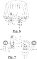
- Figure 6 illustrates the two four-bar mechanisms.
- Figure 7 shows another embodiment of the four-bar mechanism shown in figure 6 .
- the amplitude is adjusted by two adjustment means (17, 18) which change the position of the bars in the four-bar mechanism. By such a position change, the oscillating movement of the oscillatable shafts (24, 25) is changed.
- the adjustment means are located inside the housing. It is however perfectly possible to provide the adjustment means outside the housing.
- the first part of the oscillatable shaft (24) forms part of the drive mechanism (16) and is driven by the first drive means (20) via the first four-bar mechanism. Via a connecting element which forms part of this first four-bar mechanism, the oscillatable shaft (24) is connected to the first drive means (20), which in turn is connected via a connecting rod containing the two adjustment means (17, 18) to a main drive shaft which is driven by a motor.
- the mechanical coupling point of this main drive shaft to the above-mentioned connecting rod divides this connecting rod into two parts.
- the one part contains the adjustment means (17), the other part contains the adjustment means (18).
- the part connected to the drive means (20) - wherein the drive means (20) is connected thereto by the adjustment means (17) - forms part of the first four-bar mechanism.
- the first part of the oscillatable shaft (25) is driven by the second drive means (21) via the second four-bar mechanism.
- the second drive means (21) is connected to the main drive shaft via the same connecting rod as the first drive means (20), the connection being now implemented by the adjustment means (18).
- the second four-bar mechanism comprises, as well as the second drive means (21), also the connecting element between the oscillatable shaft (25) and the second drive means (21), and the second part of the connecting rod.
Landscapes
- Engineering & Computer Science (AREA)
- Textile Engineering (AREA)
- Looms (AREA)
Claims (15)
- Module de formation de foule (1) pour le déplacement sélectif d'éléments de formation de foule à l'aide d'éléments de levage (26), plusieurs éléments de formation de foule étant, lorsqu'ils sont projetés sur un plan perpendiculaire à leur direction de déplacement, situés les uns à côté des autres dans une première direction et dans une seconde direction perpendiculaire à la première direction, comprenant :- au moins deux ensembles d'éléments de levage (26) déplaçables vers le haut et vers le bas en opposition de phase ;- des éléments de formation de foule qui se déplacent de manière sélective avec les au moins deux ensembles d'éléments de levage (26) ;- au moins quatre leviers oscillants (4, 5 ; 6, 7) qui sont prévus pour déplacer les éléments de levage (26) vers le haut et vers le bas en phase et en opposition de phase selon une amplitude de déplacement réglable ;- des premier (12) et second (13) mécanismes de transfert reliés à chacun desdits deux ensembles d'éléments de levage,∘ qui comprennent chacun au moins deux desdits leviers oscillants (4, 5 ; 6, 7) situés à côté l'un de l'autre dans la première direction et∘ qui comprennent en outre chacun un mécanisme de liaison (14, 15) qui relie ensemble les leviers oscillants (4, 5 ; 6, 7) pour chaque mécanisme de transfert (12, 13), de telle sorte que ces leviers oscillants (4, 5 ; 6, 7) aient pratiquement la même amplitude de déplacement, et∘ qui sont chacun constitués des composants qui transfèrent le déplacement de l'un des au moins deux desdits leviers oscillants à l'autre,∘ les premier (12) et second (13) mécanismes de transfert étant situés l'un à côté de l'autre dans la seconde direction ;- un mécanisme d'entraînement (16) relié aux premier (12) et second (13) mécanismes de transfert,le mécanisme d'entraînement (16) ne faisant pas partie du mécanisme de transfert (12, 13),
caractérisé en ce que les éléments de levage sont accouplés par le biais des premier (12) et second (13) mécanismes de transfert au mécanisme d'entraînement (16) de telle sorte que le profil de déplacement et l'amplitude de déplacement des éléments de levage soient réglables par le biais du mécanisme d'entraînement (16). - Module de formation de foule (1) selon la revendication 1, caractérisé en ce que le mécanisme d'entraînement (16) comprend au moins deux moyens de réglage (17, 18) qui sont chacun reliés à un mécanisme de transfert (12, 13) différent, et qui sont chacun prévus pour régler de manière indépendante l'amplitude de déplacement du mécanisme de transfert associé, et qui déterminent conjointement l'amplitude de déplacement de tous les éléments de formation de foule de telle sorte que l'amplitude de déplacement de tous les éléments de formation de foule dans la première direction soit la même, et que l'amplitude de déplacement de tous les éléments de formation de foule varie de manière linéaire dans la seconde direction.
- Module de formation de foule (1) selon la revendication 2, caractérisé en ce que l'amplitude de déplacement de chaque levier oscillant (4, 5 ; 6, 7) est déterminée de manière non ambiguë par l'amplitude de déplacement du mécanisme de transfert (12, 13) relié.
- Module de formation de foule (1) selon l'une quelconque des revendications précédentes, caractérisé en ce que le mécanisme d'entraînement (16) comprend des premier et second mécanismes à quatre barres pouvant être entraînés et réglés, le premier mécanisme à quatre barres étant destiné à entraîner un levier oscillant (4, 5) du premier mécanisme de transfert (12), et le second mécanisme à quatre barres étant prévu pour entraîner un levier oscillant (6, 7) du second mécanisme de transfert (13).
- Module de formation de foule (1) selon la revendication 4, caractérisé en ce que chaque mécanisme à quatre barres comprend un moyen de réglage (17, 18).
- Module de formation de foule (1) selon la revendication 5, caractérisé en ce que le moyen de réglage (17, 18) est conçu comme une barre du mécanisme à quatre barres comportant une fente dans laquelle une autre barre (20, 21) du mécanisme à quatre barres respectif peut être déplacée afin de régler l'amplitude, ou le moyen de réglage est conçu comme une barre du mécanisme à quatre barres comportant un certain nombre de points d'accouplement (23) différents avec lesquels une autre barre (20, 21) du mécanisme à quatre barres peut être accouplée afin de régler l'amplitude.
- Module de formation de foule (1) selon la revendication 4, caractérisé en ce que le module de formation de foule (1), sur deux côtés opposés du module (1), comprend deux moyens de levage (2, 3) qui sont déplaçables vers le haut et vers le bas en opposition de phase afin de déplacer les éléments de levage (26) vers le haut et vers le bas, et chaque levier oscillant (4, 5 ; 6, 7) est relié à ces moyens de levage (2, 3) par le biais de deux bielles (19) qui sont déplaçables vers le haut et vers le bas en opposition de phase.
- Module de formation de foule (1) selon la revendication 7, caractérisé en ce que chaque levier oscillant (4, 5, 6, 7) comprend des premier (4a, 5a, 6a, 7a) et second (4b, 5b, 6b, 7b) bras de levier qui sont chacun destinés à être reliés à une extrémité de l'une des deux bielles (19).
- Module de formation de foule (1) selon la revendication 7 ou 8, caractérisé en ce que le premier mécanisme de transfert (12) comprend des premier (4) et deuxième (5) leviers oscillants, le second mécanisme de transfert (13) comprend des troisième (6) et quatrième (7) leviers oscillants, en ce que les premier (4) et troisième (6) leviers oscillants sont prévus pour déplacer les moyens de levage (2, 3) vers le haut et vers le bas en opposition de phase sur un côté du module (1), les deuxième (5) et quatrième (7) leviers oscillants sont prévus pour déplacer les moyens de levage (2, 3) vers le haut et vers le bas en opposition de phase sur l'autre côté du module (1), et en ce que le premier mécanisme à quatre barres est prévu pour entraîner le premier levier oscillant (4) par le biais d'une première bielle d'entraînement (20), et le second mécanisme à quatre barres est prévu pour entraîner le troisième levier oscillant (6) par le biais d'une seconde bielle d'entraînement (21).
- Module de formation de foule (1) selon l'une quelconque des revendications 7 à 9, caractérisé en ce que le mécanisme de liaison (14) du premier mécanisme de transfert (12) comprend un second bras de levier (8b) d'un cinquième levier oscillant (8) et un second bras de levier (9b) d'un sixième levier oscillant (9) reliés respectivement aux premier et deuxième leviers oscillants et qui sont reliés l'un à l'autre par le biais d'une bielle (22), et en ce que le mécanisme de liaison (15) du second mécanisme de transfert (13) comprend un second bras de levier (10b) d'un septième levier oscillant (10) et un second bras de levier d'un huitième levier oscillant (11) reliés respectivement aux troisième (6) et quatrième (7) leviers oscillants qui sont reliés l'un à l'autre par le biais d'une bielle (22).
- Module de formation de foule (1) selon la revendication 10, caractérisé en ce que le premier mécanisme à quatre barres est formé par le premier moyen de réglage (17), la première bielle d'entraînement (20) et le premier bras de levier (8a) du cinquième levier oscillant (8), et en ce que le second mécanisme à quatre barres est formé par le second moyen de réglage (18), la seconde bielle d'entraînement (21) et le premier bras de levier (10a) du septième levier oscillant (10).
- Module de formation de foule (1) selon l'une quelconque des revendications 4 à 7, caractérisé en ce que les premier et second mécanismes à quatre barres entraînent respectivement des premier (24) et second (25) arbres aptes à osciller.
- Machine Jacquard pourvue d'un module de formation de foule (1) selon l'une quelconque des revendications 1 à 12.
- Machine à tisser pourvue d'un module de formation de foule (1) selon l'une quelconque des revendications 1 à 12.
- Machine à tisser selon la revendication 14, caractérisé en ce que la machine à tisser comprend une machine Jacquard selon la revendication 13.
Applications Claiming Priority (2)
| Application Number | Priority Date | Filing Date | Title |
|---|---|---|---|
| BE2016/5242A BE1024029B1 (nl) | 2016-04-08 | 2016-04-08 | Gaapvormingsmodule voor een weefinrichting |
| PCT/IB2017/052049 WO2017175204A1 (fr) | 2016-04-08 | 2017-04-10 | Module de formation de foule pour dispositif de tissage |
Publications (2)
| Publication Number | Publication Date |
|---|---|
| EP3440247A1 EP3440247A1 (fr) | 2019-02-13 |
| EP3440247B1 true EP3440247B1 (fr) | 2021-07-14 |
Family
ID=56014731
Family Applications (1)
| Application Number | Title | Priority Date | Filing Date |
|---|---|---|---|
| EP17722875.6A Active EP3440247B1 (fr) | 2016-04-08 | 2017-04-10 | Module de formation de foule pour dispositif de tissage |
Country Status (7)
| Country | Link |
|---|---|
| EP (1) | EP3440247B1 (fr) |
| KR (1) | KR102402821B1 (fr) |
| CN (1) | CN109072500B (fr) |
| BE (1) | BE1024029B1 (fr) |
| ES (1) | ES2886623T3 (fr) |
| PT (1) | PT3440247T (fr) |
| WO (1) | WO2017175204A1 (fr) |
Families Citing this family (1)
| Publication number | Priority date | Publication date | Assignee | Title |
|---|---|---|---|---|
| CN114941194B (zh) * | 2022-05-16 | 2023-08-04 | 江苏谦尔乐实业有限公司 | 一种提花织机提花龙头传动装置 |
Family Cites Families (7)
| Publication number | Priority date | Publication date | Assignee | Title |
|---|---|---|---|---|
| CH590945A5 (fr) * | 1975-01-31 | 1977-08-31 | Sulzer Ag | |
| DE3721932A1 (de) | 1987-07-02 | 1989-01-19 | Grosse Webereimaschinen Gmbh | Doppelhub-offenfach-jacquardmaschine |
| FR2736939B1 (fr) * | 1995-07-18 | 1997-09-05 | Staubli Sa Ets | Mecanique jacquard a actionnement par arbres coaxiaux |
| CN2506662Y (zh) * | 2001-10-17 | 2002-08-21 | 常熟纺织机械厂有限公司 | 提花机提刀的传动机构 |
| FR2854642B1 (fr) * | 2003-05-06 | 2005-07-08 | Staubli Lyon | Dispositif de formation de la foule et metier a tisser du type jacquard equipe d'un tel dispositif |
| BE1016559A4 (nl) * | 2005-03-21 | 2007-01-09 | Wiele Michel Van De Nv | Jacquardinrichting. |
| BE1016486A4 (nl) * | 2005-04-08 | 2006-12-05 | Wiele Michel Van De Nv | Jacquardinrichting. |
-
2016
- 2016-04-08 BE BE2016/5242A patent/BE1024029B1/nl not_active IP Right Cessation
-
2017
- 2017-04-10 EP EP17722875.6A patent/EP3440247B1/fr active Active
- 2017-04-10 ES ES17722875T patent/ES2886623T3/es active Active
- 2017-04-10 PT PT177228756T patent/PT3440247T/pt unknown
- 2017-04-10 KR KR1020187031579A patent/KR102402821B1/ko not_active Expired - Fee Related
- 2017-04-10 WO PCT/IB2017/052049 patent/WO2017175204A1/fr not_active Ceased
- 2017-04-10 CN CN201780020951.7A patent/CN109072500B/zh active Active
Non-Patent Citations (1)
| Title |
|---|
| None * |
Also Published As
| Publication number | Publication date |
|---|---|
| EP3440247A1 (fr) | 2019-02-13 |
| CN109072500A (zh) | 2018-12-21 |
| WO2017175204A1 (fr) | 2017-10-12 |
| KR102402821B1 (ko) | 2022-05-26 |
| WO2017175204A4 (fr) | 2017-11-30 |
| BE1024029B1 (nl) | 2017-11-06 |
| BE1024029A1 (nl) | 2017-10-31 |
| ES2886623T3 (es) | 2021-12-20 |
| PT3440247T (pt) | 2021-09-08 |
| CN109072500B (zh) | 2020-09-22 |
| KR20180124139A (ko) | 2018-11-20 |
Similar Documents
| Publication | Publication Date | Title |
|---|---|---|
| EP2619361B1 (fr) | Dispositif de formation de la foule pour machine à tisser | |
| WO2017175204A1 (fr) | Module de formation de foule pour dispositif de tissage | |
| JP4257301B2 (ja) | 織機用杼口形成装置 | |
| US20030159746A1 (en) | Device for creating a gauze fabric | |
| CN1811035B (zh) | 促动接结和张力经纱的装置及设有该装置的绒头织物织机 | |
| CN109790657B (zh) | 用于织机的控制系统和深度学习方法 | |
| EP3425094B1 (fr) | Dispositif de commande de fil de trame sans fausse lisière dans un métier à tisser à pinces | |
| EP2929072B1 (fr) | Module approprié à une installation dans une machine jacquard | |
| EP1920094B1 (fr) | Procédé et dispositif de fabrication d un tissu de gaze sur un métier à tisser | |
| EP2135983B1 (fr) | Procédé et dispositif de fabrication d'un tapis à poils avec des hauteurs de poils variables | |
| CN108138390B (zh) | 提花机、包括至少一个提花机的面对面织机、以及设置提花机的方法 | |
| CN110168156B (zh) | 织边装置 | |
| US5257649A (en) | Jacquard housing support system | |
| EP3440248B1 (fr) | Mécanique jacquard ayant un système d'entraînement innovant | |
| EP1262584B1 (fr) | Métier pour tissu double-pièce avec formation de la foule de type double-pièce comprenant un dispositif pas de gaze et disposititif pas de gaze pour un tel métier | |
| EP1302580B1 (fr) | Dispositif pour soutenir un templet et son couvercle dans un métier à tisser un tissu éponge | |
| EP1634983A2 (fr) | Procédé et dispositif de formation de poils dans les métiers pour tissu éponge du type à toile mobile | |
| JPH11172552A (ja) | 布移動式パイル織機の経糸張力補正方法 | |
| EP3751037B1 (fr) | Machine à tisser à jet d'air pour la production de tissus de gaze | |
| JP3344702B2 (ja) | レベリング方法およびその装置 | |
| EP1498524B1 (fr) | Dispositif à commande électrique pour programmer la coupe du fil de trame dans des métiers à tisser | |
| HK40002590A (zh) | 用於织机的控制系统和深度学习方法 | |
| CN101283133A (zh) | 带有气动引纬的织机 | |
| HK1073339B (en) | Electrically-controlled device for programmable weft cutting in weaving looms |
Legal Events
| Date | Code | Title | Description |
|---|---|---|---|
| STAA | Information on the status of an ep patent application or granted ep patent |
Free format text: STATUS: UNKNOWN |
|
| STAA | Information on the status of an ep patent application or granted ep patent |
Free format text: STATUS: THE INTERNATIONAL PUBLICATION HAS BEEN MADE |
|
| PUAI | Public reference made under article 153(3) epc to a published international application that has entered the european phase |
Free format text: ORIGINAL CODE: 0009012 |
|
| STAA | Information on the status of an ep patent application or granted ep patent |
Free format text: STATUS: REQUEST FOR EXAMINATION WAS MADE |
|
| 17P | Request for examination filed |
Effective date: 20181026 |
|
| AK | Designated contracting states |
Kind code of ref document: A1 Designated state(s): AL AT BE BG CH CY CZ DE DK EE ES FI FR GB GR HR HU IE IS IT LI LT LU LV MC MK MT NL NO PL PT RO RS SE SI SK SM TR |
|
| AX | Request for extension of the european patent |
Extension state: BA ME |
|
| DAV | Request for validation of the european patent (deleted) | ||
| DAX | Request for extension of the european patent (deleted) | ||
| STAA | Information on the status of an ep patent application or granted ep patent |
Free format text: STATUS: EXAMINATION IS IN PROGRESS |
|
| 17Q | First examination report despatched |
Effective date: 20200526 |
|
| GRAP | Despatch of communication of intention to grant a patent |
Free format text: ORIGINAL CODE: EPIDOSNIGR1 |
|
| STAA | Information on the status of an ep patent application or granted ep patent |
Free format text: STATUS: GRANT OF PATENT IS INTENDED |
|
| INTG | Intention to grant announced |
Effective date: 20210329 |
|
| GRAS | Grant fee paid |
Free format text: ORIGINAL CODE: EPIDOSNIGR3 |
|
| GRAA | (expected) grant |
Free format text: ORIGINAL CODE: 0009210 |
|
| STAA | Information on the status of an ep patent application or granted ep patent |
Free format text: STATUS: THE PATENT HAS BEEN GRANTED |
|
| RIN1 | Information on inventor provided before grant (corrected) |
Inventor name: VANDERJEUGT, BRAM Inventor name: THEOBALD, MATTHEW |
|
| RAP3 | Party data changed (applicant data changed or rights of an application transferred) |
Owner name: VANDEWIELE NV |
|
| AK | Designated contracting states |
Kind code of ref document: B1 Designated state(s): AL AT BE BG CH CY CZ DE DK EE ES FI FR GB GR HR HU IE IS IT LI LT LU LV MC MK MT NL NO PL PT RO RS SE SI SK SM TR |
|
| REG | Reference to a national code |
Ref country code: GB Ref legal event code: FG4D |
|
| REG | Reference to a national code |
Ref country code: DE Ref legal event code: R096 Ref document number: 602017042094 Country of ref document: DE |
|
| REG | Reference to a national code |
Ref country code: IE Ref legal event code: FG4D |
|
| REG | Reference to a national code |
Ref country code: AT Ref legal event code: REF Ref document number: 1410731 Country of ref document: AT Kind code of ref document: T Effective date: 20210815 |
|
| REG | Reference to a national code |
Ref country code: PT Ref legal event code: SC4A Ref document number: 3440247 Country of ref document: PT Date of ref document: 20210908 Kind code of ref document: T Free format text: AVAILABILITY OF NATIONAL TRANSLATION Effective date: 20210901 |
|
| REG | Reference to a national code |
Ref country code: LT Ref legal event code: MG9D |
|
| REG | Reference to a national code |
Ref country code: NL Ref legal event code: MP Effective date: 20210714 |
|
| REG | Reference to a national code |
Ref country code: ES Ref legal event code: FG2A Ref document number: 2886623 Country of ref document: ES Kind code of ref document: T3 Effective date: 20211220 |
|
| PG25 | Lapsed in a contracting state [announced via postgrant information from national office to epo] |
Ref country code: LT Free format text: LAPSE BECAUSE OF FAILURE TO SUBMIT A TRANSLATION OF THE DESCRIPTION OR TO PAY THE FEE WITHIN THE PRESCRIBED TIME-LIMIT Effective date: 20210714 Ref country code: BG Free format text: LAPSE BECAUSE OF FAILURE TO SUBMIT A TRANSLATION OF THE DESCRIPTION OR TO PAY THE FEE WITHIN THE PRESCRIBED TIME-LIMIT Effective date: 20211014 Ref country code: FI Free format text: LAPSE BECAUSE OF FAILURE TO SUBMIT A TRANSLATION OF THE DESCRIPTION OR TO PAY THE FEE WITHIN THE PRESCRIBED TIME-LIMIT Effective date: 20210714 Ref country code: NL Free format text: LAPSE BECAUSE OF FAILURE TO SUBMIT A TRANSLATION OF THE DESCRIPTION OR TO PAY THE FEE WITHIN THE PRESCRIBED TIME-LIMIT Effective date: 20210714 Ref country code: NO Free format text: LAPSE BECAUSE OF FAILURE TO SUBMIT A TRANSLATION OF THE DESCRIPTION OR TO PAY THE FEE WITHIN THE PRESCRIBED TIME-LIMIT Effective date: 20211014 Ref country code: HR Free format text: LAPSE BECAUSE OF FAILURE TO SUBMIT A TRANSLATION OF THE DESCRIPTION OR TO PAY THE FEE WITHIN THE PRESCRIBED TIME-LIMIT Effective date: 20210714 Ref country code: SE Free format text: LAPSE BECAUSE OF FAILURE TO SUBMIT A TRANSLATION OF THE DESCRIPTION OR TO PAY THE FEE WITHIN THE PRESCRIBED TIME-LIMIT Effective date: 20210714 Ref country code: RS Free format text: LAPSE BECAUSE OF FAILURE TO SUBMIT A TRANSLATION OF THE DESCRIPTION OR TO PAY THE FEE WITHIN THE PRESCRIBED TIME-LIMIT Effective date: 20210714 |
|
| PG25 | Lapsed in a contracting state [announced via postgrant information from national office to epo] |
Ref country code: PL Free format text: LAPSE BECAUSE OF FAILURE TO SUBMIT A TRANSLATION OF THE DESCRIPTION OR TO PAY THE FEE WITHIN THE PRESCRIBED TIME-LIMIT Effective date: 20210714 Ref country code: LV Free format text: LAPSE BECAUSE OF FAILURE TO SUBMIT A TRANSLATION OF THE DESCRIPTION OR TO PAY THE FEE WITHIN THE PRESCRIBED TIME-LIMIT Effective date: 20210714 Ref country code: GR Free format text: LAPSE BECAUSE OF FAILURE TO SUBMIT A TRANSLATION OF THE DESCRIPTION OR TO PAY THE FEE WITHIN THE PRESCRIBED TIME-LIMIT Effective date: 20211015 |
|
| REG | Reference to a national code |
Ref country code: DE Ref legal event code: R097 Ref document number: 602017042094 Country of ref document: DE |
|
| PG25 | Lapsed in a contracting state [announced via postgrant information from national office to epo] |
Ref country code: DK Free format text: LAPSE BECAUSE OF FAILURE TO SUBMIT A TRANSLATION OF THE DESCRIPTION OR TO PAY THE FEE WITHIN THE PRESCRIBED TIME-LIMIT Effective date: 20210714 |
|
| PLBE | No opposition filed within time limit |
Free format text: ORIGINAL CODE: 0009261 |
|
| STAA | Information on the status of an ep patent application or granted ep patent |
Free format text: STATUS: NO OPPOSITION FILED WITHIN TIME LIMIT |
|
| PG25 | Lapsed in a contracting state [announced via postgrant information from national office to epo] |
Ref country code: SM Free format text: LAPSE BECAUSE OF FAILURE TO SUBMIT A TRANSLATION OF THE DESCRIPTION OR TO PAY THE FEE WITHIN THE PRESCRIBED TIME-LIMIT Effective date: 20210714 Ref country code: SK Free format text: LAPSE BECAUSE OF FAILURE TO SUBMIT A TRANSLATION OF THE DESCRIPTION OR TO PAY THE FEE WITHIN THE PRESCRIBED TIME-LIMIT Effective date: 20210714 Ref country code: RO Free format text: LAPSE BECAUSE OF FAILURE TO SUBMIT A TRANSLATION OF THE DESCRIPTION OR TO PAY THE FEE WITHIN THE PRESCRIBED TIME-LIMIT Effective date: 20210714 Ref country code: EE Free format text: LAPSE BECAUSE OF FAILURE TO SUBMIT A TRANSLATION OF THE DESCRIPTION OR TO PAY THE FEE WITHIN THE PRESCRIBED TIME-LIMIT Effective date: 20210714 Ref country code: CZ Free format text: LAPSE BECAUSE OF FAILURE TO SUBMIT A TRANSLATION OF THE DESCRIPTION OR TO PAY THE FEE WITHIN THE PRESCRIBED TIME-LIMIT Effective date: 20210714 Ref country code: AL Free format text: LAPSE BECAUSE OF FAILURE TO SUBMIT A TRANSLATION OF THE DESCRIPTION OR TO PAY THE FEE WITHIN THE PRESCRIBED TIME-LIMIT Effective date: 20210714 |
|
| 26N | No opposition filed |
Effective date: 20220419 |
|
| GBPC | Gb: european patent ceased through non-payment of renewal fee |
Effective date: 20220410 |
|
| PG25 | Lapsed in a contracting state [announced via postgrant information from national office to epo] |
Ref country code: MC Free format text: LAPSE BECAUSE OF FAILURE TO SUBMIT A TRANSLATION OF THE DESCRIPTION OR TO PAY THE FEE WITHIN THE PRESCRIBED TIME-LIMIT Effective date: 20210714 Ref country code: LU Free format text: LAPSE BECAUSE OF NON-PAYMENT OF DUE FEES Effective date: 20220410 Ref country code: GB Free format text: LAPSE BECAUSE OF NON-PAYMENT OF DUE FEES Effective date: 20220410 |
|
| REG | Reference to a national code |
Ref country code: AT Ref legal event code: UEP Ref document number: 1410731 Country of ref document: AT Kind code of ref document: T Effective date: 20210714 |
|
| PG25 | Lapsed in a contracting state [announced via postgrant information from national office to epo] |
Ref country code: IE Free format text: LAPSE BECAUSE OF NON-PAYMENT OF DUE FEES Effective date: 20220410 |
|
| PG25 | Lapsed in a contracting state [announced via postgrant information from national office to epo] |
Ref country code: HU Free format text: LAPSE BECAUSE OF FAILURE TO SUBMIT A TRANSLATION OF THE DESCRIPTION OR TO PAY THE FEE WITHIN THE PRESCRIBED TIME-LIMIT; INVALID AB INITIO Effective date: 20170410 |
|
| PG25 | Lapsed in a contracting state [announced via postgrant information from national office to epo] |
Ref country code: MK Free format text: LAPSE BECAUSE OF FAILURE TO SUBMIT A TRANSLATION OF THE DESCRIPTION OR TO PAY THE FEE WITHIN THE PRESCRIBED TIME-LIMIT Effective date: 20210714 Ref country code: CY Free format text: LAPSE BECAUSE OF FAILURE TO SUBMIT A TRANSLATION OF THE DESCRIPTION OR TO PAY THE FEE WITHIN THE PRESCRIBED TIME-LIMIT Effective date: 20210714 |
|
| PGFP | Annual fee paid to national office [announced via postgrant information from national office to epo] |
Ref country code: CH Payment date: 20240501 Year of fee payment: 8 |
|
| PGFP | Annual fee paid to national office [announced via postgrant information from national office to epo] |
Ref country code: ES Payment date: 20240524 Year of fee payment: 8 |
|
| PGFP | Annual fee paid to national office [announced via postgrant information from national office to epo] |
Ref country code: AT Payment date: 20240419 Year of fee payment: 8 |
|
| PGFP | Annual fee paid to national office [announced via postgrant information from national office to epo] |
Ref country code: PT Payment date: 20240328 Year of fee payment: 8 |
|
| PG25 | Lapsed in a contracting state [announced via postgrant information from national office to epo] |
Ref country code: MT Free format text: LAPSE BECAUSE OF FAILURE TO SUBMIT A TRANSLATION OF THE DESCRIPTION OR TO PAY THE FEE WITHIN THE PRESCRIBED TIME-LIMIT Effective date: 20210714 |
|
| REG | Reference to a national code |
Ref country code: CH Ref legal event code: H13 Free format text: ST27 STATUS EVENT CODE: U-0-0-H10-H13 (AS PROVIDED BY THE NATIONAL OFFICE) Effective date: 20251125 |
|
| PG25 | Lapsed in a contracting state [announced via postgrant information from national office to epo] |
Ref country code: PT Free format text: LAPSE BECAUSE OF NON-PAYMENT OF DUE FEES Effective date: 20251010 |
|
| REG | Reference to a national code |
Ref country code: AT Ref legal event code: MM01 Ref document number: 1410731 Country of ref document: AT Kind code of ref document: T Effective date: 20250410 |
|
| PG25 | Lapsed in a contracting state [announced via postgrant information from national office to epo] |
Ref country code: AT Free format text: LAPSE BECAUSE OF NON-PAYMENT OF DUE FEES Effective date: 20250410 |
|
| PG25 | Lapsed in a contracting state [announced via postgrant information from national office to epo] |
Ref country code: CH Free format text: LAPSE BECAUSE OF NON-PAYMENT OF DUE FEES Effective date: 20250430 |
|
| REG | Reference to a national code |
Ref country code: ES Ref legal event code: FD2A Effective date: 20260528 |
|
| PG25 | Lapsed in a contracting state [announced via postgrant information from national office to epo] |
Ref country code: ES Free format text: LAPSE BECAUSE OF NON-PAYMENT OF DUE FEES Effective date: 20250411 |
|
| PGFP | Annual fee paid to national office [announced via postgrant information from national office to epo] |
Ref country code: IT Payment date: 20260427 Year of fee payment: 10 |
|
| PGFP | Annual fee paid to national office [announced via postgrant information from national office to epo] |
Ref country code: DE Payment date: 20260422 Year of fee payment: 10 |
|
| PGFP | Annual fee paid to national office [announced via postgrant information from national office to epo] |
Ref country code: BE Payment date: 20260420 Year of fee payment: 10 |
|
| PGFP | Annual fee paid to national office [announced via postgrant information from national office to epo] |
Ref country code: TR Payment date: 20260406 Year of fee payment: 10 |
|
| PGFP | Annual fee paid to national office [announced via postgrant information from national office to epo] |
Ref country code: FR Payment date: 20260420 Year of fee payment: 10 |