EP3440295B1 - Ferrure de charnière avec un bras de compas pour fenêtre pivotante et basculante - Google Patents
Ferrure de charnière avec un bras de compas pour fenêtre pivotante et basculante Download PDFInfo
- Publication number
- EP3440295B1 EP3440295B1 EP17712764.4A EP17712764A EP3440295B1 EP 3440295 B1 EP3440295 B1 EP 3440295B1 EP 17712764 A EP17712764 A EP 17712764A EP 3440295 B1 EP3440295 B1 EP 3440295B1
- Authority
- EP
- European Patent Office
- Prior art keywords
- scissor
- wing
- eccentric
- spring element
- link
- Prior art date
- Legal status (The legal status is an assumption and is not a legal conclusion. Google has not performed a legal analysis and makes no representation as to the accuracy of the status listed.)
- Active
Links
Images


Classifications
-
- E—FIXED CONSTRUCTIONS
- E05—LOCKS; KEYS; WINDOW OR DOOR FITTINGS; SAFES
- E05D—HINGES OR SUSPENSION DEVICES FOR DOORS, WINDOWS OR WINGS
- E05D15/00—Suspension arrangements for wings
- E05D15/48—Suspension arrangements for wings allowing alternative movements
- E05D15/52—Suspension arrangements for wings allowing alternative movements for opening about a vertical as well as a horizontal axis
- E05D15/5205—Suspension arrangements for wings allowing alternative movements for opening about a vertical as well as a horizontal axis with horizontally-extending checks
-
- E—FIXED CONSTRUCTIONS
- E05—LOCKS; KEYS; WINDOW OR DOOR FITTINGS; SAFES
- E05F—DEVICES FOR MOVING WINGS INTO OPEN OR CLOSED POSITION; CHECKS FOR WINGS; WING FITTINGS NOT OTHERWISE PROVIDED FOR, CONCERNED WITH THE FUNCTIONING OF THE WING
- E05F7/00—Accessories for wings not provided for in other groups of this subclass
- E05F7/005—Aligning devices for wings
-
- E—FIXED CONSTRUCTIONS
- E05—LOCKS; KEYS; WINDOW OR DOOR FITTINGS; SAFES
- E05Y—INDEXING SCHEME ASSOCIATED WITH SUBCLASSES E05D AND E05F, RELATING TO CONSTRUCTION ELEMENTS, ELECTRIC CONTROL, POWER SUPPLY, POWER SIGNAL OR TRANSMISSION, USER INTERFACES, MOUNTING OR COUPLING, DETAILS, ACCESSORIES, AUXILIARY OPERATIONS NOT OTHERWISE PROVIDED FOR, APPLICATION THEREOF
- E05Y2600/00—Mounting or coupling arrangements for elements provided for in this subclass
- E05Y2600/10—Adjustable
- E05Y2600/11—Adjustable by automatically acting means
-
- E—FIXED CONSTRUCTIONS
- E05—LOCKS; KEYS; WINDOW OR DOOR FITTINGS; SAFES
- E05Y—INDEXING SCHEME ASSOCIATED WITH SUBCLASSES E05D AND E05F, RELATING TO CONSTRUCTION ELEMENTS, ELECTRIC CONTROL, POWER SUPPLY, POWER SIGNAL OR TRANSMISSION, USER INTERFACES, MOUNTING OR COUPLING, DETAILS, ACCESSORIES, AUXILIARY OPERATIONS NOT OTHERWISE PROVIDED FOR, APPLICATION THEREOF
- E05Y2800/00—Details, accessories and auxiliary operations not otherwise provided for
- E05Y2800/37—Length, width or depth adjustment
-
- E—FIXED CONSTRUCTIONS
- E05—LOCKS; KEYS; WINDOW OR DOOR FITTINGS; SAFES
- E05Y—INDEXING SCHEME ASSOCIATED WITH SUBCLASSES E05D AND E05F, RELATING TO CONSTRUCTION ELEMENTS, ELECTRIC CONTROL, POWER SUPPLY, POWER SIGNAL OR TRANSMISSION, USER INTERFACES, MOUNTING OR COUPLING, DETAILS, ACCESSORIES, AUXILIARY OPERATIONS NOT OTHERWISE PROVIDED FOR, APPLICATION THEREOF
- E05Y2900/00—Application of doors, windows, wings or fittings thereof
- E05Y2900/10—Application of doors, windows, wings or fittings thereof for buildings or parts thereof
- E05Y2900/13—Type of wing
- E05Y2900/148—Windows
Definitions
- the invention relates to a fitting arrangement according to the preamble of claim 1.
- the FR 2167494 A5 shows a fitting arrangement according to the preamble, in which the opening device for a rotatable and tiltable sash of a window or a door has a scissor cuff fixedly attached to the sash, which is coupled to an opening arm in a rotary / sliding bearing.
- the extension arm has at the end in a coupling piece a hinge hole for a hinge pin for storage in a frame on the bearing block.
- a handlebar which is pivotably mounted on the handlebar and is assigned to the scissor stay in an adjustable bracket, is also effective between the scissor stay and the extension arm.
- the handlebar is aligned in the rotational position of the opening device parallel to the scissor stay and the extension arm and causes the extension arm to be supported on the forend over the tab.
- the tab is supported by an eccentric on the scissor cuff and can be secured with a locking screw relative to the scissor cuff.
- the tab In order to change the relative position of the wing relative to the bearing block, the tab can be moved relative to the scissor stay. To do this, you must first loosen the locking screw and adjust the eccentric accordingly.
- the locking screw and eccentric are only accessible when the sash is turned and tilted, whereby the masonry makes access more difficult.
- From the DE 19718325 C1 shows an independently acting adjustment device in which two mutually movable hinge parts are provided.
- a first hinge part is attached to the frame and a second is assigned to the wing.
- the sash and frame are brought into a desired position with respect to one another by means of an alignment element, and locking elements, which fix the hinge parts to one another, act between the movable hinge parts.
- the newly defined position of the hinge parts corresponds to the target position of the sash and frame.
- the locking elements used are form-locking elements that take effect between the hinge parts.
- the disadvantage here is that a The locking elements can only be reset manually and is necessary, for example, if the sash is undesirably displaced relative to the frame not by the alignment element, but rather by incorrect operation or handling. This can, for example, be an object accidentally arranged in the fold area, by means of which the sash is raised.
- a fitting arrangement which comprises a scissor arm and a scissor arm of an opening device.
- the scissor link supports the scissor arm in a rotational opening position against a fold-side faceplate and limits the inclination of the scissor arm relative to a scissor faceplate in the tilted position.
- the scissor arm is assigned to the scissor stay face plate and the scissor link in a rotary slide connection.
- the scissor link is assigned to the scissor stay in a rotating connection.
- the scissor link is provided with coupling means which, in the rotational opening position, interact with complementary coupling means on the scissor arm and determine its relative position to the scissor arm.
- the scissor link can therefore vary its effective support length in the rotational opening position relative to the scissor arm.
- the disadvantage here is that the arrangement of the coupling means does not allow the right and left usability of the opening device, but at least limits the available space by the arrangement on the scissor arm.
- the invention is therefore based on the object of enabling a simple reset, which ideally takes place cyclically with normal use of the window or the door and which enables universal use of the fitting arrangement.
- the invention provides in a generic fitting that a first of the relatively displaceable parts of the scissor stay and the other of the parts mentioned is the handlebar, whereby between the scissor stay and handlebar is provided an adjustable tab relative to the scissor stay stay, which has the pivot bearing of the handlebar and supports an eccentric, which is effective between the scissor stay and the pivot bearing, the eccentric being acted upon by a first spring element.
- the invention thereby succeeds in ensuring universal applicability, which can be arranged practically completely in the area of the scissor stay or below and thus does not require any rebate space.
- the first spring element has an abutment on the scissor cuff and the second spring element is coupled to a drive rod which is guided below the scissor cuff and carries an abutment for this.
- the effect of the eccentric can thus be controlled via the connecting rod fitting.
- the eccentric is given an oval cross section by two eccentric bellies diametrically opposite one another on the peripheral surface.
- the first spring element is tensioned when the second spring element is relaxed in the swivel ready position of the drive rod.
- the reorientation of the fitting arrangement is achieved in that the second spring element is stretched over the drive rod in the readiness for tilting, which results in a resetting of the eccentric.
- the flap is subjected to force in the tilt-open position of the wing in the direction of the pivoting mounting of the handlebar, so that the eccentric can be moved by the spring elements without force.
- the necessary relative alignment of sash and frame is achieved in a simple manner if the opening device is arranged on a sash, which is brought into a desired position relative to the frame at least in its pivoting position in and near a surface-parallel alignment of the sash to a fixed frame via an alignment element ,
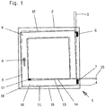
- Fig. 1 shows a window 1 consisting of a fixed frame 2 and a wing 5 pivotable therein both about a vertical axis of rotation 3 and about a horizontal axis of rotation 4.
- the frame 2 and the wing 5 are connected to one another via an upper hinge 6 and a lower hinge 7 ,
- the embodiment provides that the upper hinge 6 is designed as a so-called scissor stay, while the lower hinge 7 is designed as a so-called corner hinge.
- the wing 5 has a locking fitting (not shown here in more detail) which can be operated via a hand lever 8 on the wing 5.
- the locking fitting is designed as a tilt and turn fitting, the possibility for a pivoting movement about the lower horizontal axis of rotation 4 can also be set via the hand lever 8.
- an opening device is attached to the upper horizontal wing spar 9 with a raising arm which is movable perpendicular to the wing plane and connects the upper horizontal wing spar 9 to the upper hinge 6.
- a tilt lock - not visible here - is effective between frame 2 and wing 5, so that the lower horizontal wing edge 11 is held on frame 2.
- the frame spars of the frame 2 and the wing spars of the wing 5 do not run parallel, but have shifted into an antiparallel position due to prolonged use, wear or the like.
- an alignment element 17 is provided on the lower horizontal frame member 16, which with the fold surface 14 of the Wing 5 or a positionally stable component (not shown here) cooperates in such a way that the originally intended spacing of the folding surfaces 14, 13 is restored when the wing 5 is closed.
- the alignment element 17 consists of a casserole which is provided with an ascending slope in the direction of movement and which interacts with the rebate surface 14 of the wing.
- the wing 5 receives its original starting position 12 through the alignment element 17, in which the frame and wing spars are parallel to each other.
- the front wing edge 18 sinks down again as soon as the folded surface 14 slips off the alignment element 17. If the wing 5 is aligned antiparallel so far that the rebate surface 14 no longer meets the run-up slope of the alignment element 17, the wing 5 can only dip into the frame 2 by manually lifting the front wing edge 18.
- Tilt and turn fittings therefore provide that 6 manual adjustment options are attached to the upper hinge, which serve to restore the initial position 12.
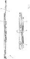
- the in the Fig. 2 Display device 19 shown attached.
- the opening device 19 is part of the turn-tilt fitting and can be brought into various functional positions via the hand lever 8.
- the opening device 19 has a drive rod 20 which is guided below a scissor stay 21.
- An extension arm 22 is guided in a longitudinally displaceable manner in an elongated hole 23 at one end in the scissor stay cover 21 and assigned to the hinge 6 in a manner (not shown here) at the other end 24.
- the deployment arm 22 with a rivet 25 passes through a guide piece 26 such that the guide piece 26 can be moved along the scissor cuff 21 and the deployment arm 22 can be pivoted about the rivet 25.
- the extension arm 22 is also connected to the scissor stay cover 21 via a link 27.
- the extension arm 22 is pivotally connected to the handlebar 27 via the rivet 28.
- the handlebar 27 is in turn pivotally associated with a bolt 29 of a bracket 30.
- the bolt 29 forms the pivot bearing of the handlebar 27 on the scissor stay 21.
- the tab 30 is displaceable along the scissor stay 21 and passes through it in an opening 31.
- An eccentric 32 is arranged between the tab 30 and the scissor cuff 21.
- the eccentric 32 has two diametrically opposite on the peripheral surface 33 Eccentric bellies 34, 35 so that it has an oval cross section.
- the eccentric 32 has a first arm 36 and a second arm 37 which protrude from partially overlapping openings 31, 38 of the scissor cuff 21 and the tab 30.
- the arm 36 protrudes above the scissor cuff 21, while the arm 37 dips below the scissor cuff 21 into a fitting receiving groove of the wing 5 and the drive rod 20 engages in an elongated hole 39.
- the arm 37 strikes an opening edge 40 of the flap 30 that widens like a funnel.
- the arm 36 also forms an indicator for the position of the eccentric 32 that is visible in the installed state of the opening device 19 the handlebar 27 facing away from the bolt 29, then the eccentric 32 is in its minimum setting.
- the eccentric 32 is so acted upon by a first spring element 41 that its eccentric belly 35 would like to step in the direction of the opening edge 42.
- the spring element 41 acts on the arm 37 and produces a corresponding torque on the eccentric 32.
- a second spring element 43 acts on the arm 37, which is relaxed in the neutral position. While the spring element 41 is fixedly assigned to the scissor stay 21 on a bracket 44, the second spring element 43 passes through an abutment 45 fastened to the drive rod 20 with a leg 46 that is guided longitudinally therein.
- the extension arm 22 is coupled at its end 24 to the hinge 6.
- the assignment to the hinge 6 fixed on the frame causes the extension arm 22 to be held in a fixed position by the alignment element 17 when the wing 5 is relatively aligned, while the scissor stay 21 with the wing 5 is relatively stationary in the Fig. 2 is moved to the left.
- the guide piece 26 compensates for this at the free end of the deployment arm 22.
- the handlebar 27 is held rigidly due to its pivotable connection to the extension arm 22, as a result of which the tab 30 is displaced within the opening 31 in the scissor stay cover 21.
- the position of the eccentric 32 and thus the setting of the opening device 19 and the leaf 5 can be reset by adjusting the tilt opening position.
- the wing 5 In the tilt-open position, the wing 5 is fixed on the lower horizontal wing spar 10 on the frame spar 16 and is thus relieved by the alignment element 17.
- the adjustment of the tilt opening position causes the drive rod 20 to be displaced into that in FIG Fig. 4 shown location.
- the abutment 45 guided together with the drive rod 20 leads to a tensioning of the spring element 43. In relation to the first spring element, this is equipped with a higher spring rate so that the force applied by the second spring element 43 exceeds that of the first spring element 41 in the tilted position.
- the spring element 43 exerts a greater torque on the eccentric 32 than the spring element 41, which leads to a rotation of the eccentric 32 counterclockwise in the figure. Since the wing 5 is relieved and aligned via the alignment element, the eccentric 32 takes on its smallest dimension with respect to the opening edges 42, 48.
- the tab 30 is subjected to force in the tilt-open position of the wing 5 in the direction of the swivel mounting of the link 27.
- This is achieved by the arrangement of the tab 30, based on the mounting points of the extension arm 22.
- the extension arm 22, the scissor stay 21 and the link 27 form a triangle, at the corners of which the rivet 25, the rivet 28 and the bolt 29 are arranged.
- the extension arm 22 is spread apart by the scissor stay 21 as a result of the opening movement of the wing 5, so that the link 27 is subjected to tension and the tab 30 is subjected to force in the direction of the rivet 28.
- the eccentric 32 variably fixes the tab 30 in different positions relative to the scissor stay 21.
- the effective length 49 of the opening device 19 results accordingly from the position of a coupling device 50 for a hinge part, which is additionally provided with a manual adjusting device 51 and the position of the bolt 29.
- the hinge 7, the opening arm 22 and the handlebar 27 and the scissor cuff 21 existing support structure can thus be adjusted in length 49 by the tab 30 determining the position of the link 27 on the scissor cuff 21 and the eccentric 32 which spreads between the tab 30 and scissor cuff 21.
- tangential surface sections can be provided on the eccentric bellies 34, 35.
Landscapes
- Engineering & Computer Science (AREA)
- Mechanical Engineering (AREA)
- Closing And Opening Devices For Wings, And Checks For Wings (AREA)
- Hinges (AREA)
- Power-Operated Mechanisms For Wings (AREA)
Claims (2)
- Ensemble de ferrure pour une fenêtre ou une porte pivotante et basculante, avec un dispositif d'orientation (19) comprenant un bras d'orientation (22) et un organe de guidage (27), qui est couplé de manière articulée avec le bras d'orientation (22), sachant que l' organe de guidage (27) peut être couplé, à un premier point de couplage d'une têtière à cisaillement (21), avec un battant (5) de la fenêtre ou de la porte, sachant que le bras d'orientation (22) peut être couplé, à un deuxième point de couplage d'un deuxième dispositif de couplage (50), avec un palier à cisaillement, qui peut être fixé sur le dormant de la fenêtre ou de la porte, afin de monter le battant (5) de manière pivotante, sur le dormant (2), sachant que deux parties d'une structure de support, comprenant le dispositif d'orientation (19) und le palier à cisaillement, peuvent être fixés variablement l'une par rapport à l'autre, dans différents positions afin de régler la longueur active (49) du dispositif d'orientation (19), et sachant que les deux parties sont reliées l'une à l'autre par l'intermédiaire d'au moins un élément de couplage (32) réglable, réalisé en tant qu'excentrique, sachant que l'une desdites partie st la têtière à cisaillement (21) et que l'autre desdites parties est l'organe de guidage (27),
sachant qu'entre la têtière à cisaillement (21) et l'organe de guidage (27), est prévue une Patte (30), qui, déplaçable par rapport á la têtière à cisaillement (21), est dotée du palier de pivotement, de l'organe de guidage (27) et porte l'excentrique (32), qui agit entre la têtière à cisaillement (21) et le palier de pivotement,
caractérisé en ce que,
l'excentrique est conçue afin de manière à ce que, lors de la fermeture du battant (5) elle soit automatiquement réglée afin qu'un réglage incorrect du battant (5) soit corrigé par modification de la longueur active (49) du dispositif d'orientation (19),
que l'excentrique (32) est soumise à l'action d'un élément faisant ressort(41),
que le premier élément faisant ressort (41) est doté d'un butée (44), sur la têtière à cisaillement (21) et que le deuxième élément faisant ressort(43) est couplé avec une tringle d'entraînement (20), qui passe au-dessous de la têtière à cisaillement (21) et est, de ce fait, dotée d'un butée (45),
que deux ventres d'excentrique (34, 35), diamétralement opposés sur la périphérie (33) confèrent à l'excentrique (32) une coupe transversale ovale, de manière à ce que, lorsque la tringle d'entrainement (20) est en position prête au basculement, le premier élément faisant ressort (41) demeure tendu alors que le deuxième élément (43) est détendu,
que, dans la position prête au basculement, le deuxième élément faisant ressort (43) est tendu par l'intermédiaire de la tringle d'entrainement (20),
et que la Patte (30), dans la position entrebâillée du battant, est actionnée en direction du palier de pivotement de l'organe de guidage (27). - Ensemble de ferrure selon la revendication 1,
caractérisé en ce que
le dispositif d'orientation (19) est disposé sur un battant (5), lequel battant (5), tout au moins dans sa position de pivotement, est orienté parallèlement au cadre fixe (2) et amené par l'intermédiaire d'un élément d'orientation (17) dans une position de consigne par rapport au cadre fixe (2).
Priority Applications (1)
| Application Number | Priority Date | Filing Date | Title |
|---|---|---|---|
| PL17712764T PL3440295T3 (pl) | 2016-04-07 | 2017-03-22 | Układ okucia z urządzeniem rozwórkowym dla rozwieranego i uchylanego skrzydła okna |
Applications Claiming Priority (2)
| Application Number | Priority Date | Filing Date | Title |
|---|---|---|---|
| DE202016002166.5U DE202016002166U1 (de) | 2016-04-07 | 2016-04-07 | Beschlaganordnung |
| PCT/EP2017/056752 WO2017174352A1 (fr) | 2016-04-07 | 2017-03-22 | Ensemble ferrure à dispositif d'extension pour fenêtres oscillo-battantes |
Publications (2)
| Publication Number | Publication Date |
|---|---|
| EP3440295A1 EP3440295A1 (fr) | 2019-02-13 |
| EP3440295B1 true EP3440295B1 (fr) | 2020-02-12 |
Family
ID=58398181
Family Applications (1)
| Application Number | Title | Priority Date | Filing Date |
|---|---|---|---|
| EP17712764.4A Active EP3440295B1 (fr) | 2016-04-07 | 2017-03-22 | Ferrure de charnière avec un bras de compas pour fenêtre pivotante et basculante |
Country Status (5)
| Country | Link |
|---|---|
| EP (1) | EP3440295B1 (fr) |
| DE (1) | DE202016002166U1 (fr) |
| PL (1) | PL3440295T3 (fr) |
| RU (1) | RU2752873C2 (fr) |
| WO (1) | WO2017174352A1 (fr) |
Cited By (1)
| Publication number | Priority date | Publication date | Assignee | Title |
|---|---|---|---|---|
| DE202023100930U1 (de) | 2023-02-28 | 2023-03-08 | Siegenia-Aubi Kg | Beschlaganordnung |
Family Cites Families (4)
| Publication number | Priority date | Publication date | Assignee | Title |
|---|---|---|---|---|
| DE2201603B2 (de) * | 1972-01-14 | 1980-04-03 | Fa. August Bilstein, 5828 Ennepetal | Ausstellvorrichtung für Kipp-Schwenk-Flügel von Fenstern oder Türen |
| DE19718325C1 (de) | 1997-04-30 | 1998-08-13 | Siegenia Frank Kg | Selbsttätig wirkende Justiervorrichtung |
| DE102014101218A1 (de) | 2014-01-31 | 2015-08-06 | Maco Technologie Gmbh | Beschlaganordnung |
| DE102014112897A1 (de) * | 2014-09-08 | 2016-03-10 | Maco Technologie Gmbh | Beschlaganordnung |
-
2016
- 2016-04-07 DE DE202016002166.5U patent/DE202016002166U1/de not_active Expired - Lifetime
-
2017
- 2017-03-22 RU RU2018134328A patent/RU2752873C2/ru active
- 2017-03-22 WO PCT/EP2017/056752 patent/WO2017174352A1/fr not_active Ceased
- 2017-03-22 PL PL17712764T patent/PL3440295T3/pl unknown
- 2017-03-22 EP EP17712764.4A patent/EP3440295B1/fr active Active
Non-Patent Citations (1)
| Title |
|---|
| None * |
Cited By (2)
| Publication number | Priority date | Publication date | Assignee | Title |
|---|---|---|---|---|
| DE202023100930U1 (de) | 2023-02-28 | 2023-03-08 | Siegenia-Aubi Kg | Beschlaganordnung |
| EP4424962A1 (fr) | 2023-02-28 | 2024-09-04 | Siegenia-Aubi KG | Ensemble ferrure |
Also Published As
| Publication number | Publication date |
|---|---|
| RU2752873C2 (ru) | 2021-08-11 |
| EP3440295A1 (fr) | 2019-02-13 |
| DE202016002166U1 (de) | 2017-07-10 |
| PL3440295T3 (pl) | 2020-07-13 |
| RU2018134328A (ru) | 2020-04-01 |
| WO2017174352A1 (fr) | 2017-10-12 |
| RU2018134328A3 (fr) | 2020-05-27 |
Similar Documents
| Publication | Publication Date | Title |
|---|---|---|
| EP3198097B1 (fr) | Charnière pour meubles | |
| EP0736659B1 (fr) | Dispositif pour le support pivotant d'un battant | |
| EP2828460B1 (fr) | Ferrure de fenetre ou porte avec un battant deplaceable vers un plan parallèle et coulissable horizontalement dans ledit plan parallèle | |
| EP0515931B2 (fr) | Ferrure pour battant oscillo-battants | |
| DE3041399C3 (de) | Drehkippbeschlag für Fenster od.dgl. | |
| DE3738596A1 (de) | Verdeckt im falz angeordneter beschlag fuer schwenklager, insb. kipp-schwenklager, fuer fluegel von fenstern, tueren oder dgl. | |
| DE3843680C2 (de) | Verdeckt angeordneter Beschlag für Schwenklager von Türen, Fenstern oder dergleichen | |
| EP3045634B1 (fr) | Dispositif orientable pour une fenetre ou une porte comprenant un dispositif de stockage d'energie | |
| EP0276678B1 (fr) | Ferrure pour porte ou fenêtre au moins pivotantes | |
| EP3440295B1 (fr) | Ferrure de charnière avec un bras de compas pour fenêtre pivotante et basculante | |
| DE2940049C2 (de) | Ausstellvorrichtung für Kipp-Schwenk-Flügel von Fenstern oder Türen | |
| DE102008028598B4 (de) | Insektenschutztür | |
| DE202007011982U1 (de) | Verstellbares Band | |
| DE2443036C3 (de) | Ausstellvorrichtung | |
| EP1117888A1 (fr) | Dispositif pour creer une fente d'aeration | |
| WO2017148663A1 (fr) | Fenêtre ou porte | |
| DE975218C (de) | Dreh-Kipp-Beschlag, insbesondere fuer grosse Fenster und Tueren | |
| DE1708443A1 (de) | Beschlag fuer Kipp-Schwenkfluegel von Fenstern | |
| WO2004063507A1 (fr) | Unite d'armature pour fenetre ou porte | |
| DE2932865A1 (de) | Beschlag fuer dachfenster | |
| DE1213290B (de) | Beschlag fuer Fensterfluegel | |
| DE10228604B3 (de) | Beschlag für ein Fenster oder eine Tür | |
| DE102005026756A1 (de) | Drehflügelbegrenzer | |
| EP2944750A1 (fr) | Protection contre une rotation excessif d'un volet pliable coulissant | |
| DE2010406B2 (de) | Ausstellvorrichtung fur Flügel von Fenstern, Türen od dgl, insbesondere Kipp Schwenkflügel |
Legal Events
| Date | Code | Title | Description |
|---|---|---|---|
| STAA | Information on the status of an ep patent application or granted ep patent |
Free format text: STATUS: UNKNOWN |
|
| STAA | Information on the status of an ep patent application or granted ep patent |
Free format text: STATUS: THE INTERNATIONAL PUBLICATION HAS BEEN MADE |
|
| PUAI | Public reference made under article 153(3) epc to a published international application that has entered the european phase |
Free format text: ORIGINAL CODE: 0009012 |
|
| STAA | Information on the status of an ep patent application or granted ep patent |
Free format text: STATUS: REQUEST FOR EXAMINATION WAS MADE |
|
| 17P | Request for examination filed |
Effective date: 20180919 |
|
| AK | Designated contracting states |
Kind code of ref document: A1 Designated state(s): AL AT BE BG CH CY CZ DE DK EE ES FI FR GB GR HR HU IE IS IT LI LT LU LV MC MK MT NL NO PL PT RO RS SE SI SK SM TR |
|
| AX | Request for extension of the european patent |
Extension state: BA ME |
|
| DAV | Request for validation of the european patent (deleted) | ||
| DAX | Request for extension of the european patent (deleted) | ||
| GRAP | Despatch of communication of intention to grant a patent |
Free format text: ORIGINAL CODE: EPIDOSNIGR1 |
|
| STAA | Information on the status of an ep patent application or granted ep patent |
Free format text: STATUS: GRANT OF PATENT IS INTENDED |
|
| INTG | Intention to grant announced |
Effective date: 20191106 |
|
| GRAS | Grant fee paid |
Free format text: ORIGINAL CODE: EPIDOSNIGR3 |
|
| GRAA | (expected) grant |
Free format text: ORIGINAL CODE: 0009210 |
|
| STAA | Information on the status of an ep patent application or granted ep patent |
Free format text: STATUS: THE PATENT HAS BEEN GRANTED |
|
| AK | Designated contracting states |
Kind code of ref document: B1 Designated state(s): AL AT BE BG CH CY CZ DE DK EE ES FI FR GB GR HR HU IE IS IT LI LT LU LV MC MK MT NL NO PL PT RO RS SE SI SK SM TR |
|
| REG | Reference to a national code |
Ref country code: GB Ref legal event code: FG4D Free format text: NOT ENGLISH |
|
| REG | Reference to a national code |
Ref country code: CH Ref legal event code: EP |
|
| REG | Reference to a national code |
Ref country code: AT Ref legal event code: REF Ref document number: 1232314 Country of ref document: AT Kind code of ref document: T Effective date: 20200215 |
|
| REG | Reference to a national code |
Ref country code: IE Ref legal event code: FG4D Free format text: LANGUAGE OF EP DOCUMENT: GERMAN |
|
| REG | Reference to a national code |
Ref country code: DE Ref legal event code: R096 Ref document number: 502017003785 Country of ref document: DE |
|
| PG25 | Lapsed in a contracting state [announced via postgrant information from national office to epo] |
Ref country code: RS Free format text: LAPSE BECAUSE OF FAILURE TO SUBMIT A TRANSLATION OF THE DESCRIPTION OR TO PAY THE FEE WITHIN THE PRESCRIBED TIME-LIMIT Effective date: 20200212 Ref country code: FI Free format text: LAPSE BECAUSE OF FAILURE TO SUBMIT A TRANSLATION OF THE DESCRIPTION OR TO PAY THE FEE WITHIN THE PRESCRIBED TIME-LIMIT Effective date: 20200212 Ref country code: NO Free format text: LAPSE BECAUSE OF FAILURE TO SUBMIT A TRANSLATION OF THE DESCRIPTION OR TO PAY THE FEE WITHIN THE PRESCRIBED TIME-LIMIT Effective date: 20200512 |
|
| REG | Reference to a national code |
Ref country code: LT Ref legal event code: MG4D |
|
| REG | Reference to a national code |
Ref country code: NL Ref legal event code: MP Effective date: 20200212 |
|
| PG25 | Lapsed in a contracting state [announced via postgrant information from national office to epo] |
Ref country code: IS Free format text: LAPSE BECAUSE OF FAILURE TO SUBMIT A TRANSLATION OF THE DESCRIPTION OR TO PAY THE FEE WITHIN THE PRESCRIBED TIME-LIMIT Effective date: 20200612 Ref country code: BG Free format text: LAPSE BECAUSE OF FAILURE TO SUBMIT A TRANSLATION OF THE DESCRIPTION OR TO PAY THE FEE WITHIN THE PRESCRIBED TIME-LIMIT Effective date: 20200512 Ref country code: HR Free format text: LAPSE BECAUSE OF FAILURE TO SUBMIT A TRANSLATION OF THE DESCRIPTION OR TO PAY THE FEE WITHIN THE PRESCRIBED TIME-LIMIT Effective date: 20200212 Ref country code: SE Free format text: LAPSE BECAUSE OF FAILURE TO SUBMIT A TRANSLATION OF THE DESCRIPTION OR TO PAY THE FEE WITHIN THE PRESCRIBED TIME-LIMIT Effective date: 20200212 Ref country code: LV Free format text: LAPSE BECAUSE OF FAILURE TO SUBMIT A TRANSLATION OF THE DESCRIPTION OR TO PAY THE FEE WITHIN THE PRESCRIBED TIME-LIMIT Effective date: 20200212 Ref country code: GR Free format text: LAPSE BECAUSE OF FAILURE TO SUBMIT A TRANSLATION OF THE DESCRIPTION OR TO PAY THE FEE WITHIN THE PRESCRIBED TIME-LIMIT Effective date: 20200513 |
|
| PG25 | Lapsed in a contracting state [announced via postgrant information from national office to epo] |
Ref country code: NL Free format text: LAPSE BECAUSE OF FAILURE TO SUBMIT A TRANSLATION OF THE DESCRIPTION OR TO PAY THE FEE WITHIN THE PRESCRIBED TIME-LIMIT Effective date: 20200212 |
|
| PG25 | Lapsed in a contracting state [announced via postgrant information from national office to epo] |
Ref country code: LT Free format text: LAPSE BECAUSE OF FAILURE TO SUBMIT A TRANSLATION OF THE DESCRIPTION OR TO PAY THE FEE WITHIN THE PRESCRIBED TIME-LIMIT Effective date: 20200212 Ref country code: DK Free format text: LAPSE BECAUSE OF FAILURE TO SUBMIT A TRANSLATION OF THE DESCRIPTION OR TO PAY THE FEE WITHIN THE PRESCRIBED TIME-LIMIT Effective date: 20200212 Ref country code: PT Free format text: LAPSE BECAUSE OF FAILURE TO SUBMIT A TRANSLATION OF THE DESCRIPTION OR TO PAY THE FEE WITHIN THE PRESCRIBED TIME-LIMIT Effective date: 20200705 Ref country code: EE Free format text: LAPSE BECAUSE OF FAILURE TO SUBMIT A TRANSLATION OF THE DESCRIPTION OR TO PAY THE FEE WITHIN THE PRESCRIBED TIME-LIMIT Effective date: 20200212 Ref country code: SM Free format text: LAPSE BECAUSE OF FAILURE TO SUBMIT A TRANSLATION OF THE DESCRIPTION OR TO PAY THE FEE WITHIN THE PRESCRIBED TIME-LIMIT Effective date: 20200212 Ref country code: SK Free format text: LAPSE BECAUSE OF FAILURE TO SUBMIT A TRANSLATION OF THE DESCRIPTION OR TO PAY THE FEE WITHIN THE PRESCRIBED TIME-LIMIT Effective date: 20200212 Ref country code: ES Free format text: LAPSE BECAUSE OF FAILURE TO SUBMIT A TRANSLATION OF THE DESCRIPTION OR TO PAY THE FEE WITHIN THE PRESCRIBED TIME-LIMIT Effective date: 20200212 Ref country code: RO Free format text: LAPSE BECAUSE OF FAILURE TO SUBMIT A TRANSLATION OF THE DESCRIPTION OR TO PAY THE FEE WITHIN THE PRESCRIBED TIME-LIMIT Effective date: 20200212 Ref country code: CZ Free format text: LAPSE BECAUSE OF FAILURE TO SUBMIT A TRANSLATION OF THE DESCRIPTION OR TO PAY THE FEE WITHIN THE PRESCRIBED TIME-LIMIT Effective date: 20200212 |
|
| REG | Reference to a national code |
Ref country code: DE Ref legal event code: R097 Ref document number: 502017003785 Country of ref document: DE |
|
| PG25 | Lapsed in a contracting state [announced via postgrant information from national office to epo] |
Ref country code: MC Free format text: LAPSE BECAUSE OF FAILURE TO SUBMIT A TRANSLATION OF THE DESCRIPTION OR TO PAY THE FEE WITHIN THE PRESCRIBED TIME-LIMIT Effective date: 20200212 |
|
| PLBE | No opposition filed within time limit |
Free format text: ORIGINAL CODE: 0009261 |
|
| STAA | Information on the status of an ep patent application or granted ep patent |
Free format text: STATUS: NO OPPOSITION FILED WITHIN TIME LIMIT |
|
| PG25 | Lapsed in a contracting state [announced via postgrant information from national office to epo] |
Ref country code: LU Free format text: LAPSE BECAUSE OF NON-PAYMENT OF DUE FEES Effective date: 20200322 |
|
| 26N | No opposition filed |
Effective date: 20201113 |
|
| PG25 | Lapsed in a contracting state [announced via postgrant information from national office to epo] |
Ref country code: IE Free format text: LAPSE BECAUSE OF NON-PAYMENT OF DUE FEES Effective date: 20200322 |
|
| PG25 | Lapsed in a contracting state [announced via postgrant information from national office to epo] |
Ref country code: SI Free format text: LAPSE BECAUSE OF FAILURE TO SUBMIT A TRANSLATION OF THE DESCRIPTION OR TO PAY THE FEE WITHIN THE PRESCRIBED TIME-LIMIT Effective date: 20200212 |
|
| PG25 | Lapsed in a contracting state [announced via postgrant information from national office to epo] |
Ref country code: MT Free format text: LAPSE BECAUSE OF FAILURE TO SUBMIT A TRANSLATION OF THE DESCRIPTION OR TO PAY THE FEE WITHIN THE PRESCRIBED TIME-LIMIT Effective date: 20200212 Ref country code: CY Free format text: LAPSE BECAUSE OF FAILURE TO SUBMIT A TRANSLATION OF THE DESCRIPTION OR TO PAY THE FEE WITHIN THE PRESCRIBED TIME-LIMIT Effective date: 20200212 |
|
| PG25 | Lapsed in a contracting state [announced via postgrant information from national office to epo] |
Ref country code: MK Free format text: LAPSE BECAUSE OF FAILURE TO SUBMIT A TRANSLATION OF THE DESCRIPTION OR TO PAY THE FEE WITHIN THE PRESCRIBED TIME-LIMIT Effective date: 20200212 Ref country code: AL Free format text: LAPSE BECAUSE OF FAILURE TO SUBMIT A TRANSLATION OF THE DESCRIPTION OR TO PAY THE FEE WITHIN THE PRESCRIBED TIME-LIMIT Effective date: 20200212 |
|
| PGFP | Annual fee paid to national office [announced via postgrant information from national office to epo] |
Ref country code: DE Payment date: 20250331 Year of fee payment: 9 |
|
| PGFP | Annual fee paid to national office [announced via postgrant information from national office to epo] |
Ref country code: PL Payment date: 20250221 Year of fee payment: 9 |
|
| PGFP | Annual fee paid to national office [announced via postgrant information from national office to epo] |
Ref country code: IT Payment date: 20250327 Year of fee payment: 9 |
|
| PGFP | Annual fee paid to national office [announced via postgrant information from national office to epo] |
Ref country code: CH Payment date: 20250401 Year of fee payment: 9 |
|
| REG | Reference to a national code |
Ref country code: CH Ref legal event code: U11 Free format text: ST27 STATUS EVENT CODE: U-0-0-U10-U11 (AS PROVIDED BY THE NATIONAL OFFICE) Effective date: 20260401 |
|
| PGFP | Annual fee paid to national office [announced via postgrant information from national office to epo] |
Ref country code: GB Payment date: 20260330 Year of fee payment: 10 |
|
| PGFP | Annual fee paid to national office [announced via postgrant information from national office to epo] |
Ref country code: AT Payment date: 20260319 Year of fee payment: 10 |
|
| PGFP | Annual fee paid to national office [announced via postgrant information from national office to epo] |
Ref country code: BE Payment date: 20260325 Year of fee payment: 10 |
|
| PGFP | Annual fee paid to national office [announced via postgrant information from national office to epo] |
Ref country code: FR Payment date: 20260330 Year of fee payment: 10 |
|
| PGFP | Annual fee paid to national office [announced via postgrant information from national office to epo] |
Ref country code: TR Payment date: 20260317 Year of fee payment: 10 |