EP3440747B1 - Système de connexion pourvu d'un dispositif de verrouillage à baïonnette conçu pour permettre une opération de déconnexion rapide - Google Patents
Système de connexion pourvu d'un dispositif de verrouillage à baïonnette conçu pour permettre une opération de déconnexion rapide Download PDFInfo
- Publication number
- EP3440747B1 EP3440747B1 EP16725609.8A EP16725609A EP3440747B1 EP 3440747 B1 EP3440747 B1 EP 3440747B1 EP 16725609 A EP16725609 A EP 16725609A EP 3440747 B1 EP3440747 B1 EP 3440747B1
- Authority
- EP
- European Patent Office
- Prior art keywords
- locking
- plug
- receptacle
- connection system
- shell
- Prior art date
- Legal status (The legal status is an assumption and is not a legal conclusion. Google has not performed a legal analysis and makes no representation as to the accuracy of the status listed.)
- Active
Links
Images



Classifications
-
- H—ELECTRICITY
- H01—ELECTRIC ELEMENTS
- H01R—ELECTRICALLY-CONDUCTIVE CONNECTIONS; STRUCTURAL ASSOCIATIONS OF A PLURALITY OF MUTUALLY-INSULATED ELECTRICAL CONNECTING ELEMENTS; COUPLING DEVICES; CURRENT COLLECTORS
- H01R13/00—Details of coupling devices of the kinds covered by groups H01R12/70 or H01R24/00 - H01R33/00
- H01R13/62—Means for facilitating engagement or disengagement of coupling parts or for holding them in engagement
- H01R13/625—Casing or ring with bayonet engagement
-
- H—ELECTRICITY
- H01—ELECTRIC ELEMENTS
- H01R—ELECTRICALLY-CONDUCTIVE CONNECTIONS; STRUCTURAL ASSOCIATIONS OF A PLURALITY OF MUTUALLY-INSULATED ELECTRICAL CONNECTING ELEMENTS; COUPLING DEVICES; CURRENT COLLECTORS
- H01R13/00—Details of coupling devices of the kinds covered by groups H01R12/70 or H01R24/00 - H01R33/00
- H01R13/62—Means for facilitating engagement or disengagement of coupling parts or for holding them in engagement
- H01R13/629—Additional means for facilitating engagement or disengagement of coupling parts, e.g. aligning or guiding means, levers, gas pressure electrical locking indicators, manufacturing tolerances
- H01R13/633—Additional means for facilitating engagement or disengagement of coupling parts, e.g. aligning or guiding means, levers, gas pressure electrical locking indicators, manufacturing tolerances for disengagement only
Definitions
- the present invention relates to a connection system comprising a plug and a receptacle, with a bayonet-type locking device suitable for mechanically locking the plug to the receptacle when they are in mutual connection configuration.
- the applications particularly targeted by the invention are the electrical connection systems which can accommodate a plurality of independent contacts or connection modules of contacts, a number of 4 or 7 contacts, or modules of contacts, typically, which are electrical and/or optical depending on the electrical and/or optical connection to be achieved. More specifically, but not only, high current and/or a high electrical power can be transmitted by this type of systems.
- the invention also relates generally to the connection systems in the outdoor applications, notably for railways and rolling vehicles and for aeronautic or military or robotics applications.
- the invention more particularly aims to propose a connection system in which the bayonet-type locking device can be disconnected fast with the unique implementing of a pulling external force.
- the bayonet-type devices are widely spread because they are efficient and allow an easy and fast manual locking.
- locking pins are engaged into locking helical ramps (slots) by rotating a part in an helical movement in a given sense, generally a clockwise sense.
- connection system is not appropriate for the applications where a fast disconnection of the connection system is required, such as in case of emergency, with or without no human intervention.
- US 4702537 patent discloses a mechanism for a quick disconnection compatible with a bayonet locking device. This mechanism requires a high precision to manufacture all the components and is complex to assemble with an important number of specific pieces, such as the ramp spring elements mounted into the first coupling ring, which increases the manufacturing costs.
- GB 2105923 describes a releasable two parts electrical connector comprising a sleeve receives over the connector parts and a coupling lug.
- the coupling lug In the coupling position, the coupling lug is urged into engagement with an external thread on one of the connector parts to hold the connector parts in a mated condition.
- An axial movement of the sleeve from the coupling position to the release position causes the coupling lug to be moved radially out of engagement with the external thread, thus permitting the separation of the connector parts.
- GB 2158301 describes an electrical connector comprising a socket, a plug, a sleeve rotatable over the plug in one direction for coupling the socket and the plug altogether.
- the sleeve comprises screw thread means, defined by a plurality of radially movable parts, and a retaining sleeve.
- the retaining sleeve restrains the movable parts, so they engage screw thread means of the outer surface of the socket.
- the retaining sleeve allows the movable parts to slide away from the screw thread means of the socket, thereby enabling the plug part and the socket part to be disconnected.
- connection systems comprising a bayonet-type locking device, in order to allow a fast and efficient disconnection between the plug and the receptacle , notably with a simple design and an easy assembly, and at reduced manufacturing costs.
- the invention aims to address all or some of this need.
- connection system of longitudinal axis X, comprising:
- bayonet-type locking device should be understood to mean a locking device that works by the cooperation of at least one pin (stud) with a ramp (slot) and which can be implemented manually without there being any need to use tools to increase the locking force by hand.
- a bayonet locking device is usually known generically as a rapid locking device.
- the invention mainly consists in defining locking pin(s) which can be disengaged elastically from the corresponding locking ramp(s) under the unique effect of a pull outside force applied on a sliding part of the locking nut.
- the invention does not require intermediate elements, such as the peripheral ramp spring elements of said patent, to release the locking pins.
- the bayonet locking device according to the invention is more simple to manufacture and to assemble compared to the disconnection system according to US 4702537 patent.
- the cross-section of the lower portion of the at least one locking pin is of a truncated cone shape and is complementary to the truncated cone shape of the cross-section of the locking ramp.
- connection system comprises three locking pins distributed at 120° relative to one another on the periphery of the locking nut, and the body of the one among the plug and the receptacle comprises three locking ramps of the same shape distributed at 120° relative to one another, any of the locking pins being suitable for cooperating with any of the ramps.
- the system comprises at least one holding pin which is mounted into the internal shell, said holding pin being adapted to maintain each flexible strip along the longitudinal axis of the plug.
- the strip avoids any lateral movement of the locking pin during the application of the pull force according to the invention.
- the system comprises at least one spring forming element arranged between the internal shell and the external shell, said spring element being adapted to push the external shell back to its position surrounding the at least one locking pin, when no pull force is applied on said external shell.
- This spring element allows to push the external shell back to its position surrounding the at least one locking pin, when no pull force is applied on said external shell.
- the spring forming element may be preferably a compression helical spring, which is very efficient and allows a compact arrangement between the internal shell and the external shell.
- the system comprises at least one an attachment flange which is attached to the sliding part of the locking nut, and a pull element attached to the attachment flange and arranged outside the locking nut in order to be accessible from the outside of the connection system comprising two attachment flanges and a flexible pull element, such as a cable, each end of which is attached to one attachment flange.
- the locking nut is mounted free in rotation around the body of the plug, while the locking ramp(s) being provided at the periphery of the body of the receptacle.
- the system constitutes a connection system comprising a plug and a receptacle, each having an insert including a plurality of cells each forming a housing for an electrical or an optical contact or contacts module.
- the invention concerns also a method of quick disconnecting the connection system mentioned above, comprising the following step:
- connection system of a circular cross-section and with a bayonet-type rapid locking device by way of example and illustration.
- connection system is particularly intended for outdoor applications, notably for railways and rolling vehicles and for aeronautic or military applications.
- This system can accommodate a plurality of independent contacts, or connection modules of contacts, a number of modules of contacts typically, which are electrical and/or optical depending on the electrical and/or optical connection to be achieved. A high current and/or a high electrical can be transmitted by this system.
- connection system may also accommodate contacts or modules for high speed electrical network applications, particularly for typical network applications like 100Mbit/s Ethernet, Gigabit Ethernet, IEEE 1394, Fibre Channel, quadrax...
- Each contact or module of contacts can be considered as a single independent connector inside the connection system, which can be separately assembled when already shielded and completed by its strain relief.
- connection system according the invention can be applied to any types of electrical and/or optical connections.
- Figure 1 represents an example of a connection system 1 of a circular cross-section, according to the invention.
- This connection system 1 comprises, respectively, a plug 2, a receptacle 3 and a manual locking device 4 suitable for mechanically locking the plug 2 to the receptacle 3 when they are in mutual connection configuration.
- the plug 2 comprises a cylindrical body 20 which includes a front through slot 21. This slot 21 forms the female part of a polarizing system between the plug 2 and the receptacle 3.
- the cylindrical body 20 is made preferably of an electrical conductive material, but may be made of an insulating material.
- the plug 2 comprises also an insert 22.
- This insert 22 may be made of an insulating material, but it may also be metallic in case of optical contacts or shielded quadrax contacts for example .
- the insert 22 includes one or a plurality of cells 23 each forming a housing for an electrical or an optical connection module or contact not shown. Each cell can be coded and identified by suitable markings over the insert 22. For a precise and reliable positioning, each module or contact may have its own guiding system inside the insert 22.
- the receptacle 3 comprises also a cylindrical body 30 which includes a front rib 31. This rib 3 is complementary to the through slot 21 and thus forms the male part of the polarizing system between the plug 2 and the receptacle 3.
- the cylindrical body 30 is made preferably in an electrical conductive material, but may be made of an insulating material.
- the cylindrical body 30 has at the periphery of its circular cross-section a flange portion 30a, which allows the receptacle 3 to be mounted on a panel, such as a control panel of instruments or on another wall of an assembly.
- the receptacle 3 comprises also an electrical insert 32.
- This insert 32 made of an insulating material, but it may also be metallic in case of optical contacts or shielded quadrax contacts for example.
- the insert 32 includes one or a plurality of cells 33, each forming a housing for an electrical or an optical contact or module not shown which is complementary to one module or contact housed in a cell 23 of the plug 2.As for the plug 2,each cell can be coded and identified by suitable markings over the insert 32, and cell may have its own guiding system inside the insert 32.
- the periphery of the body 30 is provided with one or more locking inclined helical grooves or ramps 34.
- three identical ramps 34 are distributed at 120° relative to one another.
- the manual locking device 4 for locking the plug 2 to the receptacle 3 when they are in a configuration of a mutual connection is a bayonet-type device.
- the device 4 comprises firstly a locking nut comprising two cooperating parts, the internal shell 40 and the external shell41.
- the nut is mounted free in rotation around the body 20of the plug 2.
- the external shell 41 is adapted to move in translation along said body 20 but only on a limited course.
- the locking nut comprises an internal cylindrical shell 40 adapted for accommodating the cylindrical body 20 of the plug 2.
- This internal shell 40 comprises one or more locking pins 42, each of which being protruding inwardly through an opening 43 made into the shell 40.
- three locking pins 42 are distributed at 120° relative to one another.
- Each of the locking pin 42 is fixed to the internal shell 40 by the intermediate of a plate flexible band or a flexible strip 44, which one end is secured to the locking pin 42 whereas the other end is retained by a screw 45 screwed into the internal shell 40.
- Each of the flexible strip 44 may be constituted by a metallic material.
- a supplemental pin 46 which is mounted into the internal shell 40, allows to maintain each flexible strip 44 along the longitudinal axis of the plug 2, whatever the forces applied on the locking pin 42.
- this holding pin 46 allows the strip 44 not to rotate laterally with regard to the longitudinal axis of the plug 2, when a pull force is applied on the external shell 41 of the locking nut, as detailed herein after.
- This external shell 41 is mounted around the internal shell 40 and includes a gripping zone 41a which is suitable for manual gripping.
- An attachment flange 47 is attached to the inside of the external shell 41.
- the flange 47 may be a circular plate arranged transversally to the longitudinal axis of the plug 2.
- the pull element 5 may be flexible and formed by a lanyard or a cable, or rigid under the form of a bar or a rod or a cord or any rigid piece. As shown in the illustrated embodiments, the pull element 5 may consist into a unique piece with both ends attached to the attachment element 47 or may be divided into two strands both attached to the attachment element 47.
- a handle may be arranged on the pull element 5 for facilitating a manual gripping.
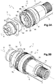
- the external shell 41 is mounted sliding around the internal shell 40 on a predetermined course. As shown in Figure 3A , the sliding mounting is achieved by a guiding pin 48 attached in the front part of the external shell 41 which can slide into the guiding groove 49 provided in the front part of the internal shell 40.
- the sliding mounting is such that:
- a preferred variant consists in a cross-section of the lower portion 42a of the at least one locking pin 42 which is of a truncated cone shape and is complementary to the truncated cone shape of the cross-section of the locking ramp 34.
- At least one spring forming element 6 is arranged between the internal shell 40 and the external shell 41.
- This spring element 6 is adapted to push the external shell 41 back to its position surrounding the at least one locking pin 42, when no pull force is applied on said external shell 41.
- the spring forming element 6 is a compression helical spring which one free end is abutment against the internal front part of the external shell 41 and the other free end is in abutment against the external rear part of the internal shell 40.
- the spring forming element 6 may be in a metallic material.
- connection system 1 with the locking bayonet-type device 4 will now be explained with reference to Figures 3A through 7C .
- each of the locking pin 42 slides along a locking ramp 34 of the receptacle 3.
- the locking operation consists on rotating the locking nut 40, 41 around the body 30 of the receptacle 3around the axis X, in the clockwise sense, i.e. according to the arrow Rc, until the limit stop is reached to produce the complete locking.
- each of the locking pin 42 slides at the extremity of the locking ramp 34 of the receptacle 3 which allows the mechanical locking between the plug 2 and the receptacle 3.
- a fast unlocking operation is represented on Figure 6 : a pull force is applied on the cable or lanyard 5 according to the arrow P, which makes the external shell 41 of the locking nut slide backward, i.e. towards to the rear part of the plug 2, due to the link with the attachment flange 47.
- the locking pins 42 are disengaged from the ramps 34 because of the relative translation between the body 30 of the receptacle 3 and the inner shell 40 of the plug 2 under the action of the pull force.
- the pull force first makes sliding backward the external shell 41 and then is transmitted to the inner shell 40 and from there to the plug 2.
- the plug 2 is thus ready to be connected and locked once again together with the receptacle 3.
- the flexible strip 44 acts as an holder designed in order to allow the disengagement of the locking pin 42 from the locking ramp 34 during the pulling step and to allow the repositioning of the locking pin 42 in the corresponding openings 43 of the internal shell 40 at the end of the pulling step.
- the locking nut 40, 41 is mounted free in rotation around the plug 2, it can be also envisaged to achieve this mounting around the receptacle 3, the locking ramps 34 being then provided around the periphery of the body 20 of the plug 2.
- the shape of the locking pins 42 and ramps 34 is a truncated cone shape, any outwardly flared shape which ensures the disengagement of the pin 42 transversally to the ramp 34 may be foreseen.
Landscapes
- Details Of Connecting Devices For Male And Female Coupling (AREA)
Claims (11)
- Système de connexion (1) d'axe longitudinal X, comprenant :- un premier élément de système formant une fiche (2) et un second élément de système formant un réceptacle (3),- un dispositif de verrouillage de type à baïonnette (4) comprenant :- un écrou de blocage (40, 41) monté de manière à être au moins libre en rotation autour de l'un de la fiche et du réceptacle,- au moins une goupille de blocage (42) agencée dans l'écrou de blocage, ladite au moins une goupille de blocage étant adaptée à être engagée dans une rampe de blocage (34) formée dans l'un parmi le réceptacle et la fiche par translation relative entre la fiche (2) et le réceptacle (3) et rotation de l'écrou de blocage de façon à bloquer mécaniquement la fiche en liaison avec le réceptacle lorsqu'ils sont en connexion mutuelle le long de l'axe longitudinal X,l'écrou de blocage comprenant une enveloppe intérieure (40) et une enveloppe extérieure (41) qui est configurée pour être montée de manière coulissante autour de l'enveloppe intérieure (40) sur une trajectoire prédéterminée,l'au moins une goupille de blocage (42) étant montée dans une ouverture de l'enveloppe intérieure (40) et attachée à l'extrémité libre d'une bande flexible (44), l'autre extrémité de la bande flexible (44) étant attachée à l'enveloppe intérieure (40), l'enveloppe extérieure (41) entourant l'au moins une goupille de blocage dans la configuration de connexion et blocage de la fiche avec le réceptacle,la disposition de ladite au moins une goupille de blocage étant telle que, lorsqu'une force de traction (P) est appliquée à l'enveloppe extérieure (41) de l'écrou de blocage, dans une direction opposée à la direction de la connexion mutuelle de la fiche avec le réceptacle le long de l'axe longitudinal X, l'enveloppe extérieure (41) est configurée pour coulisser sur l'enveloppe intérieure (40) de façon à permettre ainsi d'abord la séparation de l'enveloppe extérieure (41) vis-à-vis de la partie supérieure de l'au moins une goupille de blocage (42), puis la séparation de ladite au moins une goupille de blocage vis-à-vis de la rampe de blocage, de façon à permettre le déblocage de la fiche vis-à-vis du réceptacle, et ensuite la déconnexion mutuelle complète de la fiche vis-à-vis du réceptacle.
- Système de connexion (1) selon la revendication 1, dans lequel la section transversale de la partie inférieure (42a) de l'au moins une goupille de blocage (42) présente une forme tronconique et est complémentaire de la forme tronconique de la section transversale de la rampe de blocage (34).
- Système de connexion (1) selon la revendication 1 ou la revendication 2, comprenant trois goupilles de blocage (42) réparties à 120° les unes des autres sur la périphérie de l'écrou de blocage (40, 41), et dans lequel le corps dudit un parmi la fiche et le réceptacle comprend trois rampes de blocage (34) de la même forme réparties à 120° les unes des autres, chacune des goupilles de blocage étant adaptée à coopérer avec chacune des rampes.
- Système de connexion (1) selon l'une quelconque des revendications précédentes, comprenant au moins une goupille de retenue (46) qui est montée dans l'enveloppe intérieure (40), ladite goupille de retenue (46) étant apte à maintenir chaque bande flexible (44) le long de l'axe longitudinal de la fiche (2).
- Système de connexion (1) selon l'une quelconque des revendications précédentes 4, comprenant au moins un élément formant ressort (6) placé entre l'enveloppe intérieure (40) et l'enveloppe extérieure (41), ledit élément formant ressort (6) étant apte à pousser l'enveloppe extérieure (41) de façon à la ramener à sa position dans laquelle elle entoure l'au moins une goupille de blocage (42), lorsqu'aucune force de traction n'est appliquée à ladite enveloppe extérieure (41).
- Système de connexion (1) selon la revendication 5, dans lequel l'élément formant ressort (6) est un ressort de compression hélicoïdal.
- Système de connexion (1) selon l'une quelconque des revendications précédentes, comprenant au moins une collerette de fixation (47) qui est attachée à la partie coulissante (41) de l'écrou de blocage, et un élément de traction (5) attaché à la collerette de fixation (47) et placé à l'extérieur de l'écrou de blocage afin d'être accessible depuis l'extérieur du système de connexion.
- Système de connexion (1) selon la revendication 7, comprenant deux collerettes de fixation (47) et un élément de traction (5) flexible, tel qu'un câble, dont chaque extrémité est attachée à une collerette de fixation.
- Système de connexion (1) selon l'une quelconque des revendications précédentes, dans lequel l'écrou de blocage est monté de manière à être libre en rotation autour du corps (20) de la fiche (2), tandis la ou les rampes de blocage (34) est/sont formée(s) à la périphérie du corps (30) du réceptacle.
- Système de connexion (1) selon l'une quelconque des revendications précédentes, constituant un système d'accouplement comprenant une fiche (2) et un réceptacle (3), chacun comportant une garniture (22, 32) comprenant une pluralité de cellules (23, 33) formant chacune un logement pour un contact ou un module de contacts électrique ou optique.
- Procédé de déconnexion rapide du système de connexion (1) selon l'une quelconque des revendications précédentes, comprenant l'étape suivante :
appliquer une force de traction, dans une direction opposée à la direction de connexion mutuelle de la fiche avec le réceptacle, à l'enveloppe extérieure (41) sur une trajectoire prédéterminée de façon à amener cette dernière à coulisser sur l'enveloppe intérieure (40) sur la trajectoire prédéterminée, de façon à permettre d'abord la séparation de l'enveloppe extérieure vis-à-vis de la partie supérieure de l'au moins une goupille de blocage (42), puis la séparation de ladite goupille (42) vis-à-vis de la rampe de blocage (34) par translation relative de la fiche (2) et du réceptacle (3) .
Applications Claiming Priority (1)
| Application Number | Priority Date | Filing Date | Title |
|---|---|---|---|
| PCT/IT2016/000081 WO2017175248A1 (fr) | 2016-04-04 | 2016-04-04 | Système de connexion pourvu d'un dispositif de verrouillage à baïonnette conçu pour permettre une opération de déconnexion rapide |
Publications (2)
| Publication Number | Publication Date |
|---|---|
| EP3440747A1 EP3440747A1 (fr) | 2019-02-13 |
| EP3440747B1 true EP3440747B1 (fr) | 2022-07-06 |
Family
ID=56084277
Family Applications (1)
| Application Number | Title | Priority Date | Filing Date |
|---|---|---|---|
| EP16725609.8A Active EP3440747B1 (fr) | 2016-04-04 | 2016-04-04 | Système de connexion pourvu d'un dispositif de verrouillage à baïonnette conçu pour permettre une opération de déconnexion rapide |
Country Status (5)
| Country | Link |
|---|---|
| US (1) | US10615539B1 (fr) |
| EP (1) | EP3440747B1 (fr) |
| KR (1) | KR102205924B1 (fr) |
| CN (1) | CN109314344B (fr) |
| WO (1) | WO2017175248A1 (fr) |
Families Citing this family (12)
| Publication number | Priority date | Publication date | Assignee | Title |
|---|---|---|---|---|
| US7753246B2 (en) * | 2007-01-31 | 2010-07-13 | Tyco Healthcare Group Lp | Surgical instrument with replaceable loading unit |
| EP3826118B1 (fr) * | 2019-11-19 | 2024-11-27 | TE Connectivity Industrial GmbH | Demi-accouplement pour fiche électrique comprenant un manchon rotatif composé de plusieurs parties, ainsi que fiche électrique et procédé |
| TWI728578B (zh) * | 2019-11-28 | 2021-05-21 | 劉達民 | 具有迫緊與旋轉鎖定/解鎖之快速接頭結構 |
| FR3107997B1 (fr) * | 2020-03-09 | 2022-02-18 | Radiall Sa | Connecteur à pièce d’interface montée en rotation dans le boitier et actionnable par outil pour le coulissement d’un capot de verrouillage à un connecteur complémentaire. |
| DE102020111610B4 (de) * | 2020-04-29 | 2022-10-06 | Harting Electric Stiftung & Co. Kg | Verriegelungsmechanismus für einen Hochstromsteckverbinder |
| USD979610S1 (en) * | 2021-03-29 | 2023-02-28 | Mark A. Kelley | Outer sonde tube timed cap |
| KR200494857Y1 (ko) * | 2021-05-13 | 2022-01-11 | 초이스테크닉스 주식회사 | 잠금 장치를 구비한 원형 전기 커넥터 장치 |
| KR200496125Y1 (ko) * | 2022-01-05 | 2022-11-09 | 초이스테크닉스 주식회사 | 잠금 장치를 구비한 스크류 결합형의 전기 커넥터 장치 |
| KR200496124Y1 (ko) * | 2022-01-05 | 2022-11-09 | 초이스테크닉스 주식회사 | 잠금장치를 구비한 베이요넷 결합형의 전기 커넥터 장치 |
| CN115101992B (zh) * | 2022-06-30 | 2025-05-23 | 中车唐山机车车辆有限公司 | 一种车端电力连接器 |
| CN117184459B (zh) * | 2023-09-11 | 2025-09-12 | 哈尔滨工业大学 | 一种主被动端接口同构式快换装置 |
| CN119340737B (zh) * | 2024-12-24 | 2025-04-01 | 武汉德泰纳新能源技术有限公司 | 一种大功率充电铝导体连接装置 |
Citations (1)
| Publication number | Priority date | Publication date | Assignee | Title |
|---|---|---|---|---|
| GB2158301A (en) * | 1984-03-26 | 1985-11-06 | Plessey Co Plc | Electrical connectors |
Family Cites Families (14)
| Publication number | Priority date | Publication date | Assignee | Title |
|---|---|---|---|---|
| US3328743A (en) * | 1964-06-22 | 1967-06-27 | Northrop Corp | Quick disconnect-electrical |
| US3430184A (en) * | 1965-02-23 | 1969-02-25 | Northrop Corp | Quick disconnect electrical plug |
| US3452316A (en) * | 1965-03-22 | 1969-06-24 | Itt | Peripheral threaded tang quick-disconnect umbilical connector |
| US4307924A (en) * | 1979-11-29 | 1981-12-29 | Belden Corporation | Electrical plug having integral finger pull and cord grip |
| FR2510823A1 (fr) * | 1981-07-07 | 1983-02-04 | Bendix Corp | Connecteur electrique decrochable |
| US4447103A (en) * | 1981-12-28 | 1984-05-08 | The Bendix Corporation | Moisture seal for a separable electrical connection |
| GB2165402B (en) * | 1984-10-03 | 1988-05-25 | Cannon Electric | Electrical connector |
| US4778400A (en) * | 1984-11-29 | 1988-10-18 | Jacobs Ray T | Remote electrical connector |
| US4702537A (en) * | 1985-05-03 | 1987-10-27 | Matrix Science Corporation | Quick-disconnect electrical connector coupling assembly for use with bayonet pin coupling system |
| US4695109A (en) * | 1986-08-28 | 1987-09-22 | Allied Corporation | Quick release connector |
| GB2382733B (en) * | 2002-12-17 | 2004-02-04 | Mbm Technology Ltd | Electrical connnector |
| AU2003284403A1 (en) * | 2003-04-17 | 2004-11-04 | Canare Electric Co., Ltd. | Connector and female plug |
| JP2014241265A (ja) * | 2013-06-12 | 2014-12-25 | ファナック株式会社 | 係合方式を選択可能な電気コネクタ、および電気コネクタを備える電動機 |
| US9570848B1 (en) * | 2015-12-29 | 2017-02-14 | Jose Suarez | Electrical plug and cord kit for hair clippers |
-
2016
- 2016-04-04 KR KR1020187031931A patent/KR102205924B1/ko active Active
- 2016-04-04 WO PCT/IT2016/000081 patent/WO2017175248A1/fr not_active Ceased
- 2016-04-04 EP EP16725609.8A patent/EP3440747B1/fr active Active
- 2016-04-04 US US16/089,597 patent/US10615539B1/en active Active
- 2016-04-04 CN CN201680086195.3A patent/CN109314344B/zh active Active
Patent Citations (1)
| Publication number | Priority date | Publication date | Assignee | Title |
|---|---|---|---|---|
| GB2158301A (en) * | 1984-03-26 | 1985-11-06 | Plessey Co Plc | Electrical connectors |
Also Published As
| Publication number | Publication date |
|---|---|
| US10615539B1 (en) | 2020-04-07 |
| WO2017175248A1 (fr) | 2017-10-12 |
| KR20180124143A (ko) | 2018-11-20 |
| KR102205924B1 (ko) | 2021-01-21 |
| US20200099167A1 (en) | 2020-03-26 |
| CN109314344B (zh) | 2021-05-11 |
| EP3440747A1 (fr) | 2019-02-13 |
| CN109314344A (zh) | 2019-02-05 |
Similar Documents
| Publication | Publication Date | Title |
|---|---|---|
| US10615539B1 (en) | Connection system with a bayonet-type locking device adapted to allow a quick disconnecting operation | |
| CN104332763B (zh) | 分离脱落连接器组件及其插头和插座 | |
| US10355406B2 (en) | Electrical connector | |
| US8764473B2 (en) | Ball-lock connector | |
| EP2940361B1 (fr) | Connecteur de verrouillage à cliquet | |
| CN106165208A (zh) | 具有推挽锁定机构的电气圆形插入式连接器 | |
| EP3789648B1 (fr) | Connecteur à verrouillage de bille | |
| CN107453125B (zh) | 用于电连接器的锁定装置和配备该装置的电连接器 | |
| JP7220181B2 (ja) | ロック機構を有するプラグイン・コネクタ | |
| US8591249B2 (en) | Flexible breakaway connector | |
| EP2822105A1 (fr) | Système de couplage pour ensemble formant connecteur électrique | |
| US4907981A (en) | Quick-release electrical connector coupling device | |
| US4619491A (en) | Electric connector with pull-out plug | |
| CN109075503B (zh) | 具有闩锁释放套环的锁定特征的电连接器 | |
| CN109075504B (zh) | 具有闩锁释放套环的电连接器 | |
| EP1432082B1 (fr) | Connecteur électrique | |
| EP0247341A2 (fr) | Dispositif de raccordement autoverrouillant | |
| EP2863487A1 (fr) | Raccord de connecteur de verrouillage positif | |
| EP3186856B1 (fr) | Ensemble électrique ayant un écrou d'accouplement fileté et bague de retenue | |
| EP2904293A1 (fr) | Système de câble de manette de dérailleur à plusieurs pièces | |
| EP1085615B1 (fr) | Système connecteur | |
| US7066757B1 (en) | Enveloping pin electrical contact system | |
| EP0026556B1 (fr) | Connecteur électrique ombilical/détachable par cordon | |
| CN104283088B (zh) | 用于将接触片插入连接器的插口中的装置和方法 |
Legal Events
| Date | Code | Title | Description |
|---|---|---|---|
| STAA | Information on the status of an ep patent application or granted ep patent |
Free format text: STATUS: THE INTERNATIONAL PUBLICATION HAS BEEN MADE |
|
| PUAI | Public reference made under article 153(3) epc to a published international application that has entered the european phase |
Free format text: ORIGINAL CODE: 0009012 |
|
| STAA | Information on the status of an ep patent application or granted ep patent |
Free format text: STATUS: REQUEST FOR EXAMINATION WAS MADE |
|
| 17P | Request for examination filed |
Effective date: 20180920 |
|
| AK | Designated contracting states |
Kind code of ref document: A1 Designated state(s): AL AT BE BG CH CY CZ DE DK EE ES FI FR GB GR HR HU IE IS IT LI LT LU LV MC MK MT NL NO PL PT RO RS SE SI SK SM TR |
|
| AX | Request for extension of the european patent |
Extension state: BA ME |
|
| DAV | Request for validation of the european patent (deleted) | ||
| DAX | Request for extension of the european patent (deleted) | ||
| STAA | Information on the status of an ep patent application or granted ep patent |
Free format text: STATUS: EXAMINATION IS IN PROGRESS |
|
| 17Q | First examination report despatched |
Effective date: 20200302 |
|
| GRAP | Despatch of communication of intention to grant a patent |
Free format text: ORIGINAL CODE: EPIDOSNIGR1 |
|
| STAA | Information on the status of an ep patent application or granted ep patent |
Free format text: STATUS: GRANT OF PATENT IS INTENDED |
|
| INTG | Intention to grant announced |
Effective date: 20220218 |
|
| GRAJ | Information related to disapproval of communication of intention to grant by the applicant or resumption of examination proceedings by the epo deleted |
Free format text: ORIGINAL CODE: EPIDOSDIGR1 |
|
| STAA | Information on the status of an ep patent application or granted ep patent |
Free format text: STATUS: EXAMINATION IS IN PROGRESS |
|
| GRAP | Despatch of communication of intention to grant a patent |
Free format text: ORIGINAL CODE: EPIDOSNIGR1 |
|
| STAA | Information on the status of an ep patent application or granted ep patent |
Free format text: STATUS: GRANT OF PATENT IS INTENDED |
|
| INTC | Intention to grant announced (deleted) | ||
| INTG | Intention to grant announced |
Effective date: 20220404 |
|
| GRAS | Grant fee paid |
Free format text: ORIGINAL CODE: EPIDOSNIGR3 |
|
| GRAA | (expected) grant |
Free format text: ORIGINAL CODE: 0009210 |
|
| STAA | Information on the status of an ep patent application or granted ep patent |
Free format text: STATUS: THE PATENT HAS BEEN GRANTED |
|
| AK | Designated contracting states |
Kind code of ref document: B1 Designated state(s): AL AT BE BG CH CY CZ DE DK EE ES FI FR GB GR HR HU IE IS IT LI LT LU LV MC MK MT NL NO PL PT RO RS SE SI SK SM TR |
|
| REG | Reference to a national code |
Ref country code: AT Ref legal event code: REF Ref document number: 1503546 Country of ref document: AT Kind code of ref document: T Effective date: 20220715 Ref country code: CH Ref legal event code: EP |
|
| REG | Reference to a national code |
Ref country code: DE Ref legal event code: R096 Ref document number: 602016073319 Country of ref document: DE |
|
| REG | Reference to a national code |
Ref country code: IE Ref legal event code: FG4D |
|
| REG | Reference to a national code |
Ref country code: LT Ref legal event code: MG9D |
|
| REG | Reference to a national code |
Ref country code: NL Ref legal event code: MP Effective date: 20220706 |
|
| PG25 | Lapsed in a contracting state [announced via postgrant information from national office to epo] |
Ref country code: SE Free format text: LAPSE BECAUSE OF FAILURE TO SUBMIT A TRANSLATION OF THE DESCRIPTION OR TO PAY THE FEE WITHIN THE PRESCRIBED TIME-LIMIT Effective date: 20220706 Ref country code: RS Free format text: LAPSE BECAUSE OF FAILURE TO SUBMIT A TRANSLATION OF THE DESCRIPTION OR TO PAY THE FEE WITHIN THE PRESCRIBED TIME-LIMIT Effective date: 20220706 Ref country code: PT Free format text: LAPSE BECAUSE OF FAILURE TO SUBMIT A TRANSLATION OF THE DESCRIPTION OR TO PAY THE FEE WITHIN THE PRESCRIBED TIME-LIMIT Effective date: 20221107 Ref country code: NO Free format text: LAPSE BECAUSE OF FAILURE TO SUBMIT A TRANSLATION OF THE DESCRIPTION OR TO PAY THE FEE WITHIN THE PRESCRIBED TIME-LIMIT Effective date: 20221006 Ref country code: NL Free format text: LAPSE BECAUSE OF FAILURE TO SUBMIT A TRANSLATION OF THE DESCRIPTION OR TO PAY THE FEE WITHIN THE PRESCRIBED TIME-LIMIT Effective date: 20220706 Ref country code: LV Free format text: LAPSE BECAUSE OF FAILURE TO SUBMIT A TRANSLATION OF THE DESCRIPTION OR TO PAY THE FEE WITHIN THE PRESCRIBED TIME-LIMIT Effective date: 20220706 Ref country code: LT Free format text: LAPSE BECAUSE OF FAILURE TO SUBMIT A TRANSLATION OF THE DESCRIPTION OR TO PAY THE FEE WITHIN THE PRESCRIBED TIME-LIMIT Effective date: 20220706 Ref country code: FI Free format text: LAPSE BECAUSE OF FAILURE TO SUBMIT A TRANSLATION OF THE DESCRIPTION OR TO PAY THE FEE WITHIN THE PRESCRIBED TIME-LIMIT Effective date: 20220706 Ref country code: ES Free format text: LAPSE BECAUSE OF FAILURE TO SUBMIT A TRANSLATION OF THE DESCRIPTION OR TO PAY THE FEE WITHIN THE PRESCRIBED TIME-LIMIT Effective date: 20220706 |
|
| REG | Reference to a national code |
Ref country code: AT Ref legal event code: MK05 Ref document number: 1503546 Country of ref document: AT Kind code of ref document: T Effective date: 20220706 |
|
| PG25 | Lapsed in a contracting state [announced via postgrant information from national office to epo] |
Ref country code: PL Free format text: LAPSE BECAUSE OF FAILURE TO SUBMIT A TRANSLATION OF THE DESCRIPTION OR TO PAY THE FEE WITHIN THE PRESCRIBED TIME-LIMIT Effective date: 20220706 Ref country code: IS Free format text: LAPSE BECAUSE OF FAILURE TO SUBMIT A TRANSLATION OF THE DESCRIPTION OR TO PAY THE FEE WITHIN THE PRESCRIBED TIME-LIMIT Effective date: 20221106 Ref country code: HR Free format text: LAPSE BECAUSE OF FAILURE TO SUBMIT A TRANSLATION OF THE DESCRIPTION OR TO PAY THE FEE WITHIN THE PRESCRIBED TIME-LIMIT Effective date: 20220706 Ref country code: GR Free format text: LAPSE BECAUSE OF FAILURE TO SUBMIT A TRANSLATION OF THE DESCRIPTION OR TO PAY THE FEE WITHIN THE PRESCRIBED TIME-LIMIT Effective date: 20221007 |
|
| REG | Reference to a national code |
Ref country code: DE Ref legal event code: R097 Ref document number: 602016073319 Country of ref document: DE |
|
| PG25 | Lapsed in a contracting state [announced via postgrant information from national office to epo] |
Ref country code: SM Free format text: LAPSE BECAUSE OF FAILURE TO SUBMIT A TRANSLATION OF THE DESCRIPTION OR TO PAY THE FEE WITHIN THE PRESCRIBED TIME-LIMIT Effective date: 20220706 Ref country code: RO Free format text: LAPSE BECAUSE OF FAILURE TO SUBMIT A TRANSLATION OF THE DESCRIPTION OR TO PAY THE FEE WITHIN THE PRESCRIBED TIME-LIMIT Effective date: 20220706 Ref country code: DK Free format text: LAPSE BECAUSE OF FAILURE TO SUBMIT A TRANSLATION OF THE DESCRIPTION OR TO PAY THE FEE WITHIN THE PRESCRIBED TIME-LIMIT Effective date: 20220706 Ref country code: CZ Free format text: LAPSE BECAUSE OF FAILURE TO SUBMIT A TRANSLATION OF THE DESCRIPTION OR TO PAY THE FEE WITHIN THE PRESCRIBED TIME-LIMIT Effective date: 20220706 Ref country code: AT Free format text: LAPSE BECAUSE OF FAILURE TO SUBMIT A TRANSLATION OF THE DESCRIPTION OR TO PAY THE FEE WITHIN THE PRESCRIBED TIME-LIMIT Effective date: 20220706 |
|
| PLBE | No opposition filed within time limit |
Free format text: ORIGINAL CODE: 0009261 |
|
| STAA | Information on the status of an ep patent application or granted ep patent |
Free format text: STATUS: NO OPPOSITION FILED WITHIN TIME LIMIT |
|
| PG25 | Lapsed in a contracting state [announced via postgrant information from national office to epo] |
Ref country code: SK Free format text: LAPSE BECAUSE OF FAILURE TO SUBMIT A TRANSLATION OF THE DESCRIPTION OR TO PAY THE FEE WITHIN THE PRESCRIBED TIME-LIMIT Effective date: 20220706 Ref country code: EE Free format text: LAPSE BECAUSE OF FAILURE TO SUBMIT A TRANSLATION OF THE DESCRIPTION OR TO PAY THE FEE WITHIN THE PRESCRIBED TIME-LIMIT Effective date: 20220706 |
|
| 26N | No opposition filed |
Effective date: 20230411 |
|
| PG25 | Lapsed in a contracting state [announced via postgrant information from national office to epo] |
Ref country code: AL Free format text: LAPSE BECAUSE OF FAILURE TO SUBMIT A TRANSLATION OF THE DESCRIPTION OR TO PAY THE FEE WITHIN THE PRESCRIBED TIME-LIMIT Effective date: 20220706 |
|
| PG25 | Lapsed in a contracting state [announced via postgrant information from national office to epo] |
Ref country code: SI Free format text: LAPSE BECAUSE OF FAILURE TO SUBMIT A TRANSLATION OF THE DESCRIPTION OR TO PAY THE FEE WITHIN THE PRESCRIBED TIME-LIMIT Effective date: 20220706 |
|
| P01 | Opt-out of the competence of the unified patent court (upc) registered |
Effective date: 20230921 |
|
| REG | Reference to a national code |
Ref country code: CH Ref legal event code: PL |
|
| PG25 | Lapsed in a contracting state [announced via postgrant information from national office to epo] |
Ref country code: LU Free format text: LAPSE BECAUSE OF NON-PAYMENT OF DUE FEES Effective date: 20230404 |
|
| REG | Reference to a national code |
Ref country code: BE Ref legal event code: MM Effective date: 20230430 |
|
| PG25 | Lapsed in a contracting state [announced via postgrant information from national office to epo] |
Ref country code: MC Free format text: LAPSE BECAUSE OF FAILURE TO SUBMIT A TRANSLATION OF THE DESCRIPTION OR TO PAY THE FEE WITHIN THE PRESCRIBED TIME-LIMIT Effective date: 20220706 |
|
| PG25 | Lapsed in a contracting state [announced via postgrant information from national office to epo] |
Ref country code: MC Free format text: LAPSE BECAUSE OF FAILURE TO SUBMIT A TRANSLATION OF THE DESCRIPTION OR TO PAY THE FEE WITHIN THE PRESCRIBED TIME-LIMIT Effective date: 20220706 Ref country code: LI Free format text: LAPSE BECAUSE OF NON-PAYMENT OF DUE FEES Effective date: 20230430 Ref country code: CH Free format text: LAPSE BECAUSE OF NON-PAYMENT OF DUE FEES Effective date: 20230430 |
|
| REG | Reference to a national code |
Ref country code: IE Ref legal event code: MM4A |
|
| PG25 | Lapsed in a contracting state [announced via postgrant information from national office to epo] |
Ref country code: BE Free format text: LAPSE BECAUSE OF NON-PAYMENT OF DUE FEES Effective date: 20230430 |
|
| PG25 | Lapsed in a contracting state [announced via postgrant information from national office to epo] |
Ref country code: IE Free format text: LAPSE BECAUSE OF NON-PAYMENT OF DUE FEES Effective date: 20230404 |
|
| PG25 | Lapsed in a contracting state [announced via postgrant information from national office to epo] |
Ref country code: IE Free format text: LAPSE BECAUSE OF NON-PAYMENT OF DUE FEES Effective date: 20230404 |
|
| PG25 | Lapsed in a contracting state [announced via postgrant information from national office to epo] |
Ref country code: BG Free format text: LAPSE BECAUSE OF FAILURE TO SUBMIT A TRANSLATION OF THE DESCRIPTION OR TO PAY THE FEE WITHIN THE PRESCRIBED TIME-LIMIT Effective date: 20220706 |
|
| PG25 | Lapsed in a contracting state [announced via postgrant information from national office to epo] |
Ref country code: BG Free format text: LAPSE BECAUSE OF FAILURE TO SUBMIT A TRANSLATION OF THE DESCRIPTION OR TO PAY THE FEE WITHIN THE PRESCRIBED TIME-LIMIT Effective date: 20220706 |
|
| PGFP | Annual fee paid to national office [announced via postgrant information from national office to epo] |
Ref country code: DE Payment date: 20250319 Year of fee payment: 10 |
|
| PG25 | Lapsed in a contracting state [announced via postgrant information from national office to epo] |
Ref country code: CY Free format text: LAPSE BECAUSE OF FAILURE TO SUBMIT A TRANSLATION OF THE DESCRIPTION OR TO PAY THE FEE WITHIN THE PRESCRIBED TIME-LIMIT; INVALID AB INITIO Effective date: 20160404 |
|
| PG25 | Lapsed in a contracting state [announced via postgrant information from national office to epo] |
Ref country code: HU Free format text: LAPSE BECAUSE OF FAILURE TO SUBMIT A TRANSLATION OF THE DESCRIPTION OR TO PAY THE FEE WITHIN THE PRESCRIBED TIME-LIMIT; INVALID AB INITIO Effective date: 20160404 |
|
| PG25 | Lapsed in a contracting state [announced via postgrant information from national office to epo] |
Ref country code: TR Free format text: LAPSE BECAUSE OF FAILURE TO SUBMIT A TRANSLATION OF THE DESCRIPTION OR TO PAY THE FEE WITHIN THE PRESCRIBED TIME-LIMIT Effective date: 20220706 |
|
| PGFP | Annual fee paid to national office [announced via postgrant information from national office to epo] |
Ref country code: GB Payment date: 20260319 Year of fee payment: 11 |
|
| PGFP | Annual fee paid to national office [announced via postgrant information from national office to epo] |
Ref country code: IT Payment date: 20260319 Year of fee payment: 11 |
|
| PGFP | Annual fee paid to national office [announced via postgrant information from national office to epo] |
Ref country code: FR Payment date: 20260320 Year of fee payment: 11 |