EP3441022B1 - Instrument chirurgical - Google Patents
Instrument chirurgical Download PDFInfo
- Publication number
- EP3441022B1 EP3441022B1 EP18000326.1A EP18000326A EP3441022B1 EP 3441022 B1 EP3441022 B1 EP 3441022B1 EP 18000326 A EP18000326 A EP 18000326A EP 3441022 B1 EP3441022 B1 EP 3441022B1
- Authority
- EP
- European Patent Office
- Prior art keywords
- branch
- surgical instrument
- instrument
- instrument shaft
- sleeve
- Prior art date
- Legal status (The legal status is an assumption and is not a legal conclusion. Google has not performed a legal analysis and makes no representation as to the accuracy of the status listed.)
- Active
Links
Images


Classifications
-
- A—HUMAN NECESSITIES
- A61—MEDICAL OR VETERINARY SCIENCE; HYGIENE
- A61B—DIAGNOSIS; SURGERY; IDENTIFICATION
- A61B17/00—Surgical instruments, devices or methods
- A61B17/12—Surgical instruments, devices or methods for ligaturing or otherwise compressing tubular parts of the body, e.g. blood vessels or umbilical cord
- A61B17/122—Clamps or clips, e.g. for the umbilical cord
-
- A—HUMAN NECESSITIES
- A61—MEDICAL OR VETERINARY SCIENCE; HYGIENE
- A61B—DIAGNOSIS; SURGERY; IDENTIFICATION
- A61B17/00—Surgical instruments, devices or methods
- A61B17/28—Surgical forceps
- A61B17/2804—Surgical forceps with two or more pivotal connections
-
- A—HUMAN NECESSITIES
- A61—MEDICAL OR VETERINARY SCIENCE; HYGIENE
- A61B—DIAGNOSIS; SURGERY; IDENTIFICATION
- A61B17/00—Surgical instruments, devices or methods
- A61B17/28—Surgical forceps
- A61B17/29—Forceps for use in minimally invasive surgery
-
- A—HUMAN NECESSITIES
- A61—MEDICAL OR VETERINARY SCIENCE; HYGIENE
- A61B—DIAGNOSIS; SURGERY; IDENTIFICATION
- A61B17/00—Surgical instruments, devices or methods
- A61B17/04—Surgical instruments, devices or methods for suturing wounds; Holders or packages for needles or suture materials
- A61B17/0482—Needle or suture guides
-
- A—HUMAN NECESSITIES
- A61—MEDICAL OR VETERINARY SCIENCE; HYGIENE
- A61B—DIAGNOSIS; SURGERY; IDENTIFICATION
- A61B17/00—Surgical instruments, devices or methods
- A61B2017/00681—Aspects not otherwise provided for
- A61B2017/00738—Aspects not otherwise provided for part of the tool being offset with respect to a main axis, e.g. for better view for the surgeon
-
- A—HUMAN NECESSITIES
- A61—MEDICAL OR VETERINARY SCIENCE; HYGIENE
- A61B—DIAGNOSIS; SURGERY; IDENTIFICATION
- A61B17/00—Surgical instruments, devices or methods
- A61B17/28—Surgical forceps
- A61B2017/2808—Clamp, e.g. towel clamp
-
- A—HUMAN NECESSITIES
- A61—MEDICAL OR VETERINARY SCIENCE; HYGIENE
- A61B—DIAGNOSIS; SURGERY; IDENTIFICATION
- A61B17/00—Surgical instruments, devices or methods
- A61B17/28—Surgical forceps
- A61B17/29—Forceps for use in minimally invasive surgery
- A61B2017/2901—Details of shaft
- A61B2017/2908—Multiple segments connected by articulations
-
- A—HUMAN NECESSITIES
- A61—MEDICAL OR VETERINARY SCIENCE; HYGIENE
- A61B—DIAGNOSIS; SURGERY; IDENTIFICATION
- A61B17/00—Surgical instruments, devices or methods
- A61B17/28—Surgical forceps
- A61B17/29—Forceps for use in minimally invasive surgery
- A61B17/2909—Handles
- A61B2017/291—Handles the position of the handle being adjustable with respect to the shaft
Definitions
- the present invention comprises a medical instrument, in particular a surgical instrument, for example a vascular clamp, for occluding tubular organic, human or animal body parts, such as blood vessels, preferably arteries.
- the surgical instrument is formed from a two-part instrument shaft, a gripping device and an actuating device.
- the instrument shaft consists of two branches which have a gripping device at the distal end and an actuating device at the proximal end, one branch being displaceable relative to the other branch.
- the gripping device has two gripping elements, a first gripping element being designed in one piece and rigid with the displaceable branch.
- the second gripping element is movably arranged on the displaceable branch via a first fastening means and is movably connected to the rigid branch via a second fastening means.
- the actuating device consists of two grip elements, a first grip element being designed in one piece and rigid with the rigid branch.
- the second handle element is movably arranged on the rigid branch via a first fastening means and movably connected to the displaceable branch via a second fastening means and comprises, near the handle elements, a locking device which contains pawls with ratchet teeth with which the gripping elements are set in one of several positions can.
- the present invention relates to the field of medicine, particularly surgery.
- instruments, devices or processes are used to examine the interior of living organisms to examine and / or use for surgical interventions.
- Surgical instruments include all medical instruments that are primarily used in surgery. This also includes surgical instruments for tying off or otherwise pressing together tubular or hose-shaped body parts, preferably blood vessels. Such surgical instruments are assigned to the area of gripping or clamping instruments and are available in a wide variety of types and are well known. Gripping or clamping surgical instruments are used, for example, for interventions in cardiac, thoracic and vascular surgery. In cardiac and thoracic surgery, an open operation is usually carried out in which, for example, access to the heart is created by opening the thorax.
- Access is usually made by means of a median sternotomy, making a longitudinal incision about 25 cm long through the sternum.
- the longitudinal incision is required to open the chest.
- a thoracotomy the thorax is surgically opened through an intercostal incision, ie a small incision in the space between the ribs.
- the opening created by the sternotomy or thoracotomy is kept free by means of a rib spreader, which is used to expand the chest and keep it open.
- the opening provides the surgeon with access for surgical interventions.
- the interventions on organic parts of the body are then carried out through the opening created in the chest with the help of a variety of different surgical instruments.
- aorta is occluded around the ascending aorta with a hemostat to isolate the coronary arteries from the rest of the arterial system.
- the surgical instruments that must be used reduce the size of the opening and hinder the surgeon's work in his field of vision, and on the other hand, a rapid healing process is not to be expected in the patient due to the size of the opening, the tissue damage and the surgical trauma.
- the variety of such clamps known from the prior art include e.g. the Kocher, the Pean, the Pennington, the Foerster, and the Kowalski, to name just a few.
- all of the aforementioned clamps have the disadvantage that they are located in the surgical opening and make it smaller and / or are not suitable for minimally invasive surgery.
- a well-known example is the Kocher clamp.
- the Kocher clamp is a traumatic clamp and belongs to the class of surgical instruments to be grasped.
- Such a clamp is mainly used when structures have to be gripped, held and compressed in the process.
- the Kocher clamp has corrugated branches so that the gripped tissue does not slip out of the branches.
- such a clamp lies directly in the surgical opening.
- Curved aortic clips are also known, e.g. according to Huland and Noldus, which are used for dissecting between the rectum and Denonvillier's fascia during prostatectomy in order to avoid injuries to the rectum. Due to the curved gripping elements, these instruments can already be moved to the edge of the operating room opening, but still reduce the size of the operating room opening.
- the search results show the large number of aortic clamps.
- the clamp can have handle elements angled towards the instrument shaft, whereby the clamp is relatively close to the The edge of an operation opening can be relocated, but the grip elements still remain in the operation opening in a disruptive manner.
- Another example of a clamp is disclosed in US Pat DE 200 16 854 U1 .
- This clamp comprises a body with a tool carrier head and several levers for moving the tool, the levers being articulated on the body and the handle sections of these levers being inclined with respect to their pivot plane. Also the handle elements are still annoying.
- the process of clamping blood vessels using the surgical instruments listed above is based on the same principle.
- the two branches of the surgical instruments are moved towards and away from each other with the help of ring handles.
- a ratchet or locking device with which the branches can be set in one of several individual positions, is arranged on the scissor members.
- the setting of the distances between the branches can therefore only be done in stages.
- the big disadvantage of a graduation is that a vessel is either too tight or too weak.
- the closest prior art is the subject of DE 696 32 451 T2 viewed.
- the disclosed subject matter relates, for example, according to paragraphs [0034] to [0038] and the Figure 4 in the published document, a pair of pliers.
- the pliers have a manual actuating element, a gripping device which is functionally connected to the actuating element via a two-part body element, and two gripping elements.
- the gripping elements are adapted to open or close in response to movement of the actuating element, wherein a the gripping plane spanned by the gripping device is angled against the longitudinal axis of the body element.
- a common feature of all the aforementioned surgical instruments is their size, the scissors-like shape with predominantly ring-shaped handles for actuating the branches and a typical locking device.
- the latest developments in cardiac, thoracic and vascular surgery which show a way to minimally invasive surgery, reduce the size of the access opening in the thorax, especially in thoracotomy, in order to reduce tissue damage and surgical trauma to the patient and to accelerate the healing process achieve.
- small access openings have the disadvantage that the surgical instruments that are necessarily inserted in the opening significantly reduce the size of the operating field or the visual field, which makes the operation more difficult.
- the path taken in minimally invasive surgery can therefore only be achieved if the surgical instruments used are adapted to the new requirements of the smaller operating room openings. That is, the embodiments of the surgical clips should be adapted to the medical requirements of the surgical interventions. Surgical interventions are also carried out more quickly in order to reduce the stress on the patient and the risk of side effects. For this purpose, atraumatic instruments are required, the handling of which makes the surgical procedure much easier.
- the invention is therefore based on the object of creating a medical instrument of the type mentioned at the beginning for use in surgery.
- the surgical instrument is intended to avoid the aforementioned disadvantages and inadequacies of the known arrangements and to provide a technical solution.
- the technical solution consists in an expanded functionality of the surgical instrument, it being intended to be able to produce the expanded technical functionality in a cost-effective manner.
- the technical functionality consists in the to spend annular grip elements outside of the operating field.
- the surgical instrument should therefore have the same properties as the surgical clamps known from the prior art and additionally offer advantageous handling, whereby the operating field or the surgeon's field of vision is not reduced, but enlarged.
- a surgical instrument for use in surgical interventions on the human or animal body in surgery
- the aforementioned objects had to be achieved. The object is achieved in replacing the previously known scissors-like surgical instruments with ring-shaped handles and a stepped locking mechanism by the prior art instrument shown below and providing them with additional functions.
- the pliers from the DE 696 32 451 T2 to use and develop them further.
- the further development consists in equipping the body element of the aforementioned clamp with an inventive lockable joint mechanism without restricting the normal function of the clamp.
- a hinge mechanism makes it possible to move part of the clamp outside of the operating room opening.
- An example of a joint mechanism can DE 60 2004 011 298 T2 can be removed, this hinge mechanism not for use on the pliers from the DE 696 32 451 T2 is suitable and cannot pivot the actuating device out of the OP opening.
- the surgical instrument is formed from a two-part instrument shaft, a gripping device, an actuating device and a locking element.
- Generic instruments of the present invention are classified in the group of sliding-shaft instruments.
- Such sliding shaft instruments are used in particular in the field of minimally invasive endoscopic interventions.
- they have a thin, elongated shaft with a diameter between 5 mm and 15 mm.
- a work tool is provided as a gripping device at its distal end.
- This gripping device generally has a movable tool element in the form of gripping elements, which is designed in particular as pliers, as a cutting device or as a gripping clamp.
- the movement of the gripping device is brought about by the actuating device provided at the proximal end of the shaft.
- this is a scissor handle device with a laterally arranged fixed branch and a handle branch or a handle element mounted on it pivotably.
- the instrument shaft is used to transmit an actuating movement and a pivoting movement that is suitable for a joint axis running perpendicular to the longitudinal axis and perpendicular to the axes of the fastening means, the instrument shaft consisting of two branches that have a gripping device at the distal end and an actuating device at the proximal end , whereby one branch can be moved relative to the other branch and both branches have an articulated mechanism.
- the gripping device of the surgical instrument has two gripping elements, a first gripping element being integral and rigid with the displaceable branch and the second gripping element being movably arranged on the displaceable branch via a first fastening means and movably connected to the rigid branch via a second fastening means.
- the actuation device of the surgical instrument consists of two grip elements, a first grip element being integral and rigid with the rigid branch and the second grip element being movably arranged on the rigid branch via a first fastening means and movably connected to the displaceable branch via a second fastening means.
- the actuating device comprises a locking device close to the grip elements, which contain pawls having ratchet teeth.
- the instrument shaft which consists of two branches, into two proximal and two distal branch parts, with one end of the two proximal branch parts being connected to the grip elements and the other end of the two distal branch parts being connected to the gripping elements.
- This advantage of dividing the instrument shaft is used to equip the instrument shaft according to the invention with a hinge mechanism at the separation point.
- a hinge mechanism is arranged at the free, facing ends of the branch parts, between the proximal and distal branch parts.
- a joint mechanism advantageously consists of a joint, the joint being formed from a groove and a spring.
- a joint is arranged between the branch parts of the first branch, which are divided into proximal and distal.
- the second branch here too there is a joint between the branch, which is also divided into two branches.
- the proximal branch part is designed with a tongue and the distal branch part with a groove, the tongue engaging in the groove and being connected to it via a fastening means, creating an articulated connection between the branch parts.
- the tongue and the groove are interchanged, so that the groove is in the proximal branch and the tongue in the distal branch part.
- the surgical instrument can be used as a surgeon in spite of the locking element, it must first fulfill the normal functions as a clamp before the actuating device can be pivoted.
- the actuating device When the actuating device is operated, one movable branch (with one proximal and distal branch part and one joint) of the instrument shaft moves axially against the other rigid branch (with the two other branch parts and the other joint) of the instrument shaft, whereby the Gripping device is opened or closed. Because the joint remains within the locking element when the movable branch is displaced, there is a fixed joint all the time, which is moved axially back and forth with the movable branch. Due to the fixed joint, the gripping device can be opened and closed.
- the surgical instrument is single-acting and with a clamp straight gripping elements executed. Only when the actuating device is actuated when the surgical instrument and thus the gripping device is opened does the movable branch move in the axial direction towards the gripping device and axially back again to the starting position when the surgical instrument or the gripping device is closed with the aid of the actuating device. Due to the displacement of the movable branch in both axial directions, when opening and closing the gripping device, the joint is also displaced in the axial direction with respect to the joint of the fixed branch. The displacement of the movable branch in the axial direction only takes place when the locking element is in the locking position over the joint mechanism and simultaneously over the two branches, as in the Figure 2a shown is located.
- the surgical instrument is therefore designed with a locking element which comprises the movable joints between the branch parts in order to fix the joints and thus prevent the branch parts from pivoting.
- the locking element in the locking position includes not only the two joints, but also the proximal and distal branch parts of the instrument shaft to the right and left of the joints, so that it is not possible to pivot the branch parts around the joint.
- the blocking element must enable the surgical clamp to function.
- the function consists in opening and closing the gripping device by operating the actuating device. The movement of the gripping device at the distal end is brought about by the actuating device present at the proximal end of the shaft. Only after the surgical instrument has grasped and occluded a tubular body part is the blocking element moved out of the blocking position.
- the further advantage comes into play by moving the locking element on the instrument shaft from the locking position into a release position.
- the locking element is displaced in the axial direction along the longitudinal axis of the instrument shaft of the surgical instrument.
- the axial displacement of the locking element on the instrument shaft can advantageously both in Take place in the direction of the grip elements and in the direction of the gripping elements. In both directions there is a release position for the locking element on the instrument shaft, in which the joints of the branch parts are released.
- the locking element In the release position, the locking element only comprises a distal or proximal part of the two branch parts. As in the locked position, it does not cover all four distal and proximal branches, including the two joints.
- the advantage of the displacement of the locking element is that the released joint mechanism enables a pivoting movement of the actuating device in order to pivot the actuating device with the gripping device lying in one plane out of the common longitudinal axis of the surgical instrument.
- the advantageous pivoting of the actuating device enables the surgeon to have a clearer view of the operating room opening.
- the surgical instrument can be removed again by pivoting the swiveled out branch parts with the actuating device back onto the common longitudinal axis of the instrument and shifting the locking element from the release position back into the locking position, whereby the locking element is again over all four branch parts and engages the two joints.
- the gripping device can be opened again via the actuating device, the occluded body part can be released again and the instrument can be removed from the body opening.
- the locking element is advantageously provided with latching means which securely fix the locking element in the release or locking position.
- a further advantage of the surgical instrument according to the invention is that the instrument complies with the provisions of the Medical Products Act and, due to the materials used, is suitable for use for sterilization during cleaning.
- the inventive surgical instrument equipped with a hinge mechanism and a locking element for the hinge mechanism, can be manufactured in a cost-effective manner because the slidable locking element is designed in such a way that it does not hinder the axial movement of the slidable branch to the rigid branch.
- the locking effect of the locking element on the joint mechanism can be achieved solely through the contact surfaces (inner surfaces) of the locking element against the contact surfaces (outer surfaces) of the instrument shaft and when the locking element engages in the area of the joints in both directions over the proximal and distal branch parts, i.e. in the locked position.
- the locking element can advantageously be made of a plastic material and thereby fulfill the desired functionality.
- Various metals that are approved for medical purposes can also be used.
- plastic materials are inexpensive to manufacture.
- the surgical instrument 1 shown in a basic illustration from the prior art represents a pair of forceps with a thread guide and consists essentially of an actuating device 2 , a body element 4, hereinafter referred to as the instrument shaft 4, and a gripping device 3 .
- the actuating device 2 has a leg 46 which is designed in one piece with the branch 11 of the instrument shaft 4 and the grip element 9 , as well as a movable grip element 10 which is arranged on the leg of the actuating device 2 so as to be rotatable about a fastening means 15 (pivot pin).
- the leg 46, including the rigid grip element 9 and the movable grip element 10 of the actuating device 2 are provided with a finger loop.
- the movable grip element 10 of the actuating device 2 carries a pin 16 on which a rear end of a further branch 12 of the instrument shaft 4 is rotatably mounted.
- One of the gripping elements 7 of the gripping device 3 is made in one piece with the branch 12 .
- the other gripping element 6 of the gripping device 3 is rotatably connected at one end, in the vicinity of the foot of the gripping element 7, to a pin 14 of the branch 12 and through a pin 13, in the vicinity of the pin 14, rotatable to a front end of the branch 11 connected.
- the surgical instrument 1 carries out the opening and closing operations in the following way: When the actuating device 2 is operated, the branch 12 of the instrument shaft 4 moves axially against the branch 11 of the instrument shaft 4. The pin 14 and the pin 13 are shifted against each other and the gripping member 6 is controlled, whereby the gripping device 3 is opened or closed.
- the surgical instrument 1 is designed as a single-acting clamp and with straight gripping elements 6, 7 .
- the free end sections of the gripping element 7 and the gripping element 6 can each be bent at an angle to the longitudinal axis 25 of the instrument shaft 4 (not shown), and the thread guide 47 can be arranged within the gripping plane spanned by the bent sections. Due to a different use of the inventive surgical instrument 1, as in the in Figure 2 shown, the thread guide 47 is omitted for the clamp .
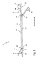
- FIG.2a is a schematic representation of a surgical instrument 1 according to the invention with locking element 27 in the locking position 28, shown .
- the in the Figure 1 The reference symbols shown are adopted here analogously.
- the description of the surgical instrument 1 from FIG Figure 1 can for that, in the Figure 2
- the inventive surgical instrument 1 shown can be partially adopted because the base of the surgical instrument 1, as in FIG Figure 1 shown, in the embodiment of the surgical instrument 1 in FIG Figure 2 corresponds.
- the embodiment has a long instrument shaft 4 , which differs from the scissors-like clamps from the prior art, in which the legs from the handle to the clamp branch are continuous and integral and overlap with a common pivot bearing in the intersection area.
- the length of the instrument shaft 4 is designed for the use of the instrument 1 in minimally invasive surgery.
- transthoracic clamps are used in operations under endoscopic view. These instruments are used, for example, for small lateral access openings in the space between the ribs of a chest, for example in the right thoracic area, in order to gain access to the aorta in the left chest.
- Chitwood clamp e.g. Scanlan International, St. Paul, Minn.
- This is introduced into the thorax through a stab incision in the approx. 3rd ICR cranial to the thoracotomy and used for external clamping of the ascending aorta.
- the clamp is inserted through the transverse sinus under visual control.
- attention is paid to the left atrial appendage so as not to injure it.
- To clamp the aorta the HLM is briefly stopped so that the clamping can take place in a controlled manner and without a lever.
- the inventive surgical instrument 1 is formed from a long two-part instrument shaft 4, a gripping device 3, an actuating device 2 and a locking element 27 and is shown in the open state of the gripping device 3 and with the actuating device 2 not locked.
- the instrument shaft 4 ensures the transmission of an actuation movement, starting from the grip elements 9, 10 via the branches 11, 12 of the instrument shaft 4 to the gripping elements 6, 7 and also ensures the pivoting movement of the actuation device 2 about a hinge axis 26, 26 ', which is arranged perpendicular to the longitudinal axis 25 and perpendicular to the axes of the fastening means 13, 14, 15, 16 .
- the instrument shaft 4 consists of two branches 11, 12 which have a gripping device 3 at the distal end 5 and an actuating device 2 at the proximal end 8 , one branch 12 being displaceable relative to the other branch 11 and both branches 11, 12 a hinge mechanism 24, 24 ' with a hinge axis 26, 26' , see Figure 2b exhibit.
- the locking element 27 is in a locked locking position 28 .
- the joints 20, 21 of the joint mechanism 24, 24 ' or their two joint axes 26, 26' are on a common center line 34, see FIG Figure 2b .
- the movable branch 12 move in the axial direction 35 towards the gripping device 3 and when the surgical instrument 1 or the gripping device 3 is closed with the aid of the actuating device 2, axially back to the starting position.
- the hinge axis 26 ' By shifting the branch 12 in both axial directions 35 when opening and closing the gripping device 3, the hinge axis 26 ' also shifts in the axial direction 35 relative to the hinge axis 26 of the stationary branch 11.
- the displacement of the movable branch 12 in the axial direction 35 occurs only when the locking element 27 is in the locking position 28 over the joint mechanism 24, 24 ' and at the same time over the two branches 11, 12, as in FIG Figure 2a shown is located.
- the joint 21 of the branch 12 is thus only back and forth in the axial direction 35 of the gripping device 3 located at the distal end 5 axially displaceable back into the starting position. In the starting position, the center line 34 'of the joint 21 is congruent with the center line 34 of the joint 20.
- the gripping device 3 has two gripping elements 6, 7 , a first gripping element 7 being designed in one piece and rigid with the displaceable branch 12 and the second gripping element 6 being movably arranged on the displaceable branch 12 via a first fastening means 14 and via a second fastening means 13 is movably connected to the rigid branch 11 .
- the actuating device 2 on the other hand, consists of two grip elements 9, 10, a first grip element 9 being designed in one piece and rigid with the rigid branch 11 and the second grip element 10 being movably arranged on the rigid branch 11 via a first fastening means 15 and a second fastening means 16 is movably connected to the displaceable branch 12 .
- the actuating device 2 comprises, close to the grip elements 9, 10, a locking device 19, which contains pawls 17, 18 having locking teeth 22, 23 . From the Figure 2a it can also be seen that the actuating device 2 is not in a locked position.
- the ratchet teeth 22, 23 of the pawls 17, 18 interact and the gripping elements 6, 7 of the gripping device 3 comprise a body part or, as in the present illustration, the gripping elements 6, 7 are in the open position.
- the closed position of the gripping elements 6, 7 of the surgical instrument 1 the pawls 17, 18 lie one above the other and the ratchet teeth 22, 23 mesh with one another.
- the locking element 27 is in the locked locking position 28 above the joints 20, 21 of the branches 11, 12 of the instrument shaft 4, whereby a pivoting of the actuating device 2 from the longitudinal axis 25 with respect to the gripping device 3 is not possible. Nevertheless, in the blocking position 28 of the blocking element 27, the gripping device 3 can be opened and closed by moving the branch 12 with the aid of the actuating device 2 .
- a surgical instrument 1 according to the invention with a locking element 27 in the release position 29, 29 ' is shown in a schematic representation.
- The, in the Figure 1 and Figure 2a The reference symbols shown are adopted here analogously.
- the description of the surgical instrument 1 from FIG Figure 1 and Figure 2a will for that, in the Figure 2b inventive surgical instrument 1 shown, partly adopted.
- the locking element 27 located in a locked first release position 29 on the instrument shaft 4 releases the joints 20, 21 of the joint mechanism 24, 24 'of the instrument shaft 4 consisting of branches 11, 12 .
- the joints 20, 21 are released by shifting the locking element 27 from the locking position 28 in the axial direction 35 up to a release position 29, 29 ' .
- the axial displacement of the locking element 27 on the instrument shaft 4 can take place both in the direction of the distal end 5 and in the direction of the proximal end 8 of the surgical instrument 1 .
- the axial displacement of the locking element 27 in both directions takes place only until the two joints 20, 21 are released.
- the locking element 27 is in the release position 29.
- Two release positions 29, 29 ′ are provided for the locking element 27 .
- the first release position 29 of the locking element 27 is located in the distal branch part 11.2, 12.2, while the second release position 29 'is arranged in the proximal branch part 11.1, 12.1 .
- the locking position 28 and the two release positions 29, 29 ′ for the locking element 27 can be provided with locking elements 45 on or in the instrument shaft 4 in order to limit the axial sliding path of the locking element 27 .
- the locking element 27 can also be provided with locking means 42, see FIG Figure 3a , be formed, wherein these locking means 42 of the locking element 27 correspond to the locking means 45 of the instrument shaft 4 . Due to the latching means 42, 45, the locking element 27 is fixed in the locking position 28 or the release position 29, 29 ' .
- the two branches 11, 12 of the instrument shaft 4 are each formed from a proximal and distal branch part 11.1, 11.2, 12.1, 12.2 , one end 8 of the proximal branch part 11.1, 12.1 with the grip element 9, 10 and one end 5 of the distal branch part 11.2, 12.2 with the gripping element 6, 7 connected is.
- a joint mechanism 24, 24 ' At the other distal and proximal end of the branch parts 11.1, 11.2, 12.1, 12.2 there is a joint mechanism 24, 24 ' .
- This means that a joint mechanism 24, 24 ' is arranged between the distal and proximal branch parts 11.1, 11.2, 12.1, 12.2 .
- each branch 11, 12 has its own joint mechanism 24, 24 ' .
- Both articulation mechanisms 24, 24 ′ are encompassed by a single locking element 27 .
- the joint mechanism 24, 24 ′ is released. After the joint mechanisms 24, 24 ′ have been released , a pivoting movement of the actuating device 2 is made possible without actuating the grip elements 9, 10 .
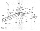
- the actuating device 2 can thus be articulated from the common longitudinal axis 25 with the gripping device 3 lying in one plane, see FIG Figure 2c , be pivoted without the gripping elements 6, 7 experience a change in location.
- Each joint mechanism 24, 24 ' comprises a joint 20, 21, which on the proximal or distal side of the branch part 11.1, 11.2, 12.1, 12.2 has a spring 30, 30' and on the opposite distal side facing the spring 30, 30 ' or proximal side of the branch part 11.1, 11.2, 12.1, 12.2, a corresponding groove 31, 31 ' .
- the tongue 30, 30 ' and the groove 31, 31' interlock and are connected by a fastening means consisting of a hinge axis 26, 26 ' . That is, the tongue 30, 30 ' can both on the branch part 11.1 and 12.1 and the groove 31, 31' on the branch part 11.2 and 12.2, as from the Figure 2b can be seen to be arranged.
- the groove 30, 30 'and the spring 31, 31' be arranged oppositely to, then the spring 30, 30 'at the branch part 11.2 and 12.2 and the groove 31, 31' located at the branch part 11.1 and 12.1.
- the joint mechanism is therefore not limited to the aforementioned embodiment.
- the locking element 27 has an opening 32, see Figure 3a , which corresponds to the shape of the instrument shaft 4 and a displacement of the displaceable branch 12 during the locked position 28 of the joint 20, 21, see Figure 2a , made possible by the locking element 27 in the direction of the longitudinal axis 25 .
- FIG.2c is a schematic representation of an instrument shaft 4 of the surgical instrument 1, according to FIG Figure 2a and Figure 2b , visible in an angled position.
- the proximal branch parts 11.1, 12.1 of the branches 11, 12 of the instrument shaft 4 are angled by approx. 60 degrees from the longitudinal axis 25 compared to the distal branch parts 11.2, 12.2 and the actuating device 2, not shown, is thus angled by 60 degrees to the gripping device 3 .
- the adjustable angle 33 of the actuating device 2 pivotable about the joint 20, 21 can be between 0 degrees and 120 degrees; the angle 33 can advantageously be set continuously between 0 degrees and 90 degrees.
- the spring 30, 30 'of the joint 20, 21 is used not only for the rotatable attachment of the branch parts 11.1, 12.1 in the groove 31, 31' of the branch parts 11.2, 12.1, but also the joint mechanism 24, 24 ' as a maximum angle stop.
- connection between the tongue 30, 30 ' and the groove 31, 31' takes place via the hinge axis 26, 26 ' and is technically designed in such a way that a rotation about the hinge axis 26, 26' or a pivoting of the proximal branches 11.1, 12.1 of the instrument shaft 4 around the joint 20, 21 takes place relatively easily, so that virtually no forces act on the gripping device 3 and thus on the occluded tubular body part.
- the joint mechanism 24, 24 ' is designed to be self-locking, so that the branch parts 11.1, 12.1 or branch parts 11.2, 12.2 can only be rotated or pivoted around the joint 20, 21 with the help of the surgeon.
- the locking element 27 is in the release position 29 ' in the proximal area of the branch parts 11.1, 12.1 of the instrument shaft 4.
- the locking means 45 arranged in the instrument shaft 4 in the area of the joint mechanism 24 are visible because the locking element 27 is not in the locking position 28, but in the release position 29 ' is located.
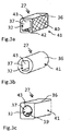
- the Fig. 3a, 3b, 3c show a schematic representation of a first embodiment of a blocking element 27 of the surgical instrument 1 according to the invention.
- the surgical instrument 1 has two inventive technical elements with which new functions of the surgical instrument 1 are made possible.
- the first inventive solution consists in the arrangement of a joint mechanism 24, 24 ' in the instrument shaft 4, see Figure 2b , 2c .
- the second solution consists in the design and function of a locking element 27 for fixing or releasing the joints 20, 21 of the instrument shaft 4, see also Figure 2b , 2c .
- the function of the locking element 27 consists on the one hand, when it is in the locking position 28 , to prevent the joints 20, 21 of the instrument shaft 4 from rotating and thus to fix the joints 20, 21 in order to allow normal gripping and closing activity with the surgical Instrument 1 to be able to perform.
- the function of the locking element 27 is to release the joints 20, 21 when the locking element 27 is in the release position 29, 29 'in order to enable the actuating device 2 to pivot about the joints 20, 21 , with the set gripping elements 6 , 7 of the gripping device 3 remain in their brought position and continue to hold an occluded body element.
- the pivoting movement of the two branch parts 11.1, 12.1 with respect to the branch parts 11.2, 12.2 can be blocked by the blocking element 27 .
- the locking position 28 is given when the locking element 27 is directly above the hinge mechanism 24, 24 ', see Figure 2a , is located and at the same time engages over the proximal branch parts 11.1, 12.1 and the distal branch parts 11.2, 12.2 .
- the joints 20, 21 are locked in the locked position 28 by the inner surfaces 37 of the locking element 27 resting against the outer surfaces 38 of the instrument shaft 4.
- the blocking element 27 is, as shown in FIG Figure 3a can be seen, approximately around a sleeve 36 which, in a first embodiment, is box-shaped.
- the sleeve 36 has an opening 32 which corresponds approximately to a rectangular through hole, see Figure 3a .
- the rectangular inner shape 43 (inner contour) of the through hole corresponds to the rectangular outer shape 44 (outer contour) of the instrument shaft 4, the inner surfaces 37 of the through hole always resting on the outer surfaces 38 of the instrument shaft 4 , also in the release position 29, 29 ' or during the axial displacement of the locking element 27 along the branches 11, 12.
- the shape 44 of the branches 11 , 12 of the instrument shaft 4 thus determine the shape 43 of the through-hole in the sleeve 36 of the locking element 27.
- the opening 32 is as Inner contour 43 of the sleeve 36 is also round, see Figure 3c .
- Other inner contours 43 of the sleeves 36 are conceivable and depend on the outer shape 44 (outer contour) of the instrument shafts 4. Regardless of the shape 44 of the instrument shaft 4 , the inner surfaces 37 of the sleeve 36 always serve as a contact surface for the outer surfaces 38 of the branches 11, 12, and the legs of the branches 11, 12 serve the sleeve 36 as a sliding guide.
- the relative length of the sleeve 36 is designed such that the sleeve 36 in the locking position 28 still extends to the right and left of the joints 20, 21 over the proximal and distal branch parts 11.1, 12.1, 11.2, 12.2 in order to prevent the actuating device 2 from pivoting .
- the shape of the outer contour 41 of the sleeve 36 can also be designed differently.
- the outer contour 41 can be modeled on an instrument shaft 4 or as in FIG Figure 3c shown, have a square outer contour 41 or like the Figure 3b can be seen to be formed from a circular outer contour 41 .
- the outer contour 41 of a sleeve 36 can in turn have a raised surface profile 40 or depressions in order to improve handling for the surgeon.
- the surface profile 40 of the sleeve 36 can be corrugated so that an operator can easily grip the locking element 27 axially on the instrument shaft 4 and move it.
- the sleeve 36 of the locking element 27 can be equipped with latching means 42 , see Figure 3a , these locking means 42 of the locking element 27 corresponding to the locking means 45 of the instrument shaft 4 . Due to the locking means 42, the locking element 27 is fixed in the locking position 28 or the release position 29, 29 ' .
- the locking means 42 of the sleeve 36 consist of one or more elevations, for example cams, which are arranged in the opening 32 of the sleeve 36 . The cams can be arranged at the beginning and at the end of the opening 32 of the sleeve 36 , for example.
- An instrument shaft 4 has one or more corresponding depressions as corresponding latching means 45, see Figure 2b in which one of the cams of the sleeve 36 can correspondingly engage.
- a plurality of depressions are advantageously arranged in the instrument shaft 4 , etc. in the area of the locking position 28 of the locking element 27 and in the area of the release position 29, 29 ' in order to fix the locking element 27 .
- a feather key 39 can be arranged in the through-bore, which key can engage in a corresponding groove in the instrument shaft 4 (not shown).
- further locking means in the sleeve 36 for fixing the locking element 27 and on the instrument shaft 4 are conceivable and are not limited to the specified locking means 42, 45 .
- the sleeve 36 of the locking element 27 can have depressions and the instrument shaft 4 elevations as latching means 42, 45 .
Landscapes
- Health & Medical Sciences (AREA)
- Surgery (AREA)
- Life Sciences & Earth Sciences (AREA)
- Medical Informatics (AREA)
- Animal Behavior & Ethology (AREA)
- Engineering & Computer Science (AREA)
- Biomedical Technology (AREA)
- Heart & Thoracic Surgery (AREA)
- Veterinary Medicine (AREA)
- Molecular Biology (AREA)
- Nuclear Medicine, Radiotherapy & Molecular Imaging (AREA)
- General Health & Medical Sciences (AREA)
- Public Health (AREA)
- Ophthalmology & Optometry (AREA)
- Reproductive Health (AREA)
- Vascular Medicine (AREA)
- Surgical Instruments (AREA)
Claims (8)
- Instrument chirurgical (1) pour l'occlusion de parties organiques de forme tubulaire du corps, composé d'une tige d'instrument en deux parties (4), d'un système de préhension (3), d'un système d'actionnement (2), le système d'actionnement (2) étant composé de deux éléments poignées (9, 10) et le premier élément poignée (9) ayant une conformation monobloc avec la branche rigide (11) et rigide et le second élément poignée (10) étant disposé de manière mobile au niveau de la branche rigide (11) par l'intermédiaire d'un premier moyen de fixation (15) est étant connecté de manière mobile par un second élément de fixation (16) à la branche déplaçable (12) et le système d'actionnement (2) présentant, à proximité des éléments poignées (9, 10), un dispositif d'arrêt (19) qui contient des cliquets (17, 18) présentant des dents d'enclenchement (22, 23) et le système de préhension (3) présentant deux éléments de préhension (6, 7), un premier élément de préhension (7) ayant une conformation monobloc avec la branche déplaçable (12) et rigide et le second élément de préhension (6) étant disposé de manière mobile par l'intermédiaire d'un premier moyen de fixation (14) au niveau de la branche déplaçable (12) et étant connecté de manière mobile par un second moyen de fixation (13) à la branche rigide (11), caractérisé en ce que la tige d'instrument (4), qui est apte à transférer un mouvement d'actionnement et un mouvement de pivotement autour d'un axe d'articulation (26) s'étendant perpendiculairement à l'axe longitudinal (25) et perpendiculairement aux axes des moyens de fixation (13, 14, 15, 16), est composé de deux branches (11, 12) qui présentent à l'extrémité distale (5) un système de préhension (3) et à l'extrémité proximale (8) un système d'actionnement (2), une branche (12) étant déplaçable par rapport à l'autre branche (11) et les deux branches (11, 12) présentant un mécanisme d'articulation (24, 24') qui est entouré par un élément de blocage (27) qui se présente sous forme d'un manchon (36).
- Instrument chirurgical (1) selon la revendication 1, caractérisé en ce que les deux branches (11, 12) de la tige d'instrument (4) sont constituées respectivement d'un élément de branche proximal et distal (11.1, 11.2, 12.1, 12.2), les deux éléments de branche proximaux (11.1, 12.1) étant connectés à un élément poignée (9, 10) et les deux éléments de branches distaux (11.2, 12.2) étant connectés à un élément de préhension (6, 7).
- Instrument chirurgical (1) selon la revendication 2, caractérisé en ce que, entre les éléments de branche (11.1, 11.2, 12.1, 12.2), est disposé respectivement un mécanisme d'articulation (24, 24') qui est entouré d'un élément de blocage (27), sachant que, après le décalage de l'élément de blocage (27) de la position de blocage (28) vers une position de déblocage (29, 29'), un mouvement de pivotement du système d'actionnement (2) devient possible pour pivoter de manière articulée le système d'actionnement (2) avec le système de préhension se trouvant dans un plan (3) depuis l'axe longitudinal commun (25).
- Instrument chirurgical (1) selon la revendication 3, caractérisé en ce que le mécanisme d'articulation (24, 24') comprend une articulation (20, 21) qui présente un ressort (30, 30') du côté proximal et distal de l'élément de branche (11.1, 11.2, 12.1, 12.2) et, du côté distal ou proximal composé de l'élément de branche (11.1, 11.2, 12.1, 12.2), une rainure correspondante (31, 31'), lesquels ressort et rainure s'engrènent l'un dans l'autre et sont connectés par un moyen de fixation (26, 26').
- Instrument chirurgical (1) selon la revendication 3, caractérisé en ce que l'élément de blocage (27) constitue un manchon (36) qui présente une ouverture (32), l'ouverture (32) du manchon (36) qui correspond à la forme extérieure (44) de la tige d'instrument (4) et qui permet un décalage de la branche déplaçable (12), en position de blocage (28) de l'articulation (20, 21), à travers l'élément de blocage (27) dans les deux sens de l'axe longitudinal (25).
- Instrument chirurgical (1) selon la revendication 5, caractérisé en ce que l'ouverture (32) du manchon (36) présente des moyens d'enclenchement (42) qui correspondent à des moyens d'enclenchement (45) de la tige d'instrument (4) dans la position de blocage (28) et de déblocage (29, 29') de l'élément de blocage (27).
- Instrument chirurgical (1) selon la revendication 6, caractérisé en ce que les moyens d'enclenchement (42) constituent dans le manchon (36) des protubérances et que les moyens d'enclenchement (45) constituent dans la tige d'instrument (4) des creux ou que le manchon (36) présente des creux et la tige d'instrument (4) des protubérances.
- Instrument chirurgical (1) selon la revendication 5, caractérisé en ce que le manchon (36) est fabriqué en matière plastique.
Applications Claiming Priority (1)
| Application Number | Priority Date | Filing Date | Title |
|---|---|---|---|
| DE202017004226.6U DE202017004226U1 (de) | 2017-08-11 | 2017-08-11 | Chirurgisches Instrument |
Publications (2)
| Publication Number | Publication Date |
|---|---|
| EP3441022A1 EP3441022A1 (fr) | 2019-02-13 |
| EP3441022B1 true EP3441022B1 (fr) | 2020-08-19 |
Family
ID=60119102
Family Applications (1)
| Application Number | Title | Priority Date | Filing Date |
|---|---|---|---|
| EP18000326.1A Active EP3441022B1 (fr) | 2017-08-11 | 2018-04-06 | Instrument chirurgical |
Country Status (3)
| Country | Link |
|---|---|
| EP (1) | EP3441022B1 (fr) |
| DE (1) | DE202017004226U1 (fr) |
| ES (1) | ES2832732T3 (fr) |
Cited By (1)
| Publication number | Priority date | Publication date | Assignee | Title |
|---|---|---|---|---|
| EP4059447A2 (fr) | 2021-03-17 | 2022-09-21 | CARDIOMEDICAL GmbH | Instrument chirurgical |
Families Citing this family (2)
| Publication number | Priority date | Publication date | Assignee | Title |
|---|---|---|---|---|
| US11564733B2 (en) | 2018-01-17 | 2023-01-31 | Covidien Lp | Surgical instruments incorporating ultrasonic and electrosurgical functionality |
| CN114010291B (zh) * | 2021-03-31 | 2024-05-24 | 上海焰医数字医疗科技有限公司 | 一种骨折外固定夹子及其系统 |
Family Cites Families (9)
| Publication number | Priority date | Publication date | Assignee | Title |
|---|---|---|---|---|
| US5490819A (en) * | 1991-08-05 | 1996-02-13 | United States Surgical Corporation | Articulating endoscopic surgical apparatus |
| JP2873366B2 (ja) | 1996-04-01 | 1999-03-24 | ▼しずか▲ 加▼せ▲田 | 鉗 子 |
| IT247792Y1 (it) | 1999-10-05 | 2002-09-10 | Bidoia Sas Di Gianfranco Bidoi | Struttura di pinza ad uso chirurgico |
| DE60218240T2 (de) * | 2001-04-18 | 2007-11-22 | Olympus Corporation | Chirurgisches Instrument |
| DE20112540U1 (de) | 2001-07-30 | 2001-10-31 | Aesculap AG & Co. KG, 78532 Tuttlingen | Medizinisches Instrument |
| US7111769B2 (en) | 2003-07-09 | 2006-09-26 | Ethicon Endo-Surgery, Inc. | Surgical instrument incorporating an articulation mechanism having rotation about the longitudinal axis |
| DE202007016057U1 (de) | 2007-11-15 | 2008-01-17 | Cardiomedical Gmbh | Chirurgisches Instrument |
| DE202008001675U1 (de) | 2008-02-06 | 2008-04-17 | Weinmann Gmbh, Chirurgische Instrumente | Zerlegbares chirurgisches Instrument |
| US8529445B2 (en) * | 2010-05-17 | 2013-09-10 | DePuy Synthes Products, LLC | Spreading retractor |
-
2017
- 2017-08-11 DE DE202017004226.6U patent/DE202017004226U1/de active Active
-
2018
- 2018-04-06 EP EP18000326.1A patent/EP3441022B1/fr active Active
- 2018-04-06 ES ES18000326T patent/ES2832732T3/es active Active
Non-Patent Citations (1)
| Title |
|---|
| None * |
Cited By (3)
| Publication number | Priority date | Publication date | Assignee | Title |
|---|---|---|---|---|
| EP4059447A2 (fr) | 2021-03-17 | 2022-09-21 | CARDIOMEDICAL GmbH | Instrument chirurgical |
| EP4059447A3 (fr) * | 2021-03-17 | 2022-11-23 | CARDIOMEDICAL GmbH | Instrument chirurgical |
| US11771438B2 (en) | 2021-03-17 | 2023-10-03 | Cardiomedical Gmbh | Surgical instrument |
Also Published As
| Publication number | Publication date |
|---|---|
| EP3441022A1 (fr) | 2019-02-13 |
| ES2832732T3 (es) | 2021-06-11 |
| DE202017004226U1 (de) | 2017-10-04 |
Similar Documents
| Publication | Publication Date | Title |
|---|---|---|
| EP0910293B1 (fr) | Instrument avec deux pinces independantes | |
| DE69326998T2 (de) | Endoskopisches chirurgisches Gelenkwerkzeug | |
| EP2335609B1 (fr) | Instrument chirurgical | |
| DE212019000498U1 (de) | Gleitschlitz-Mehrarmklemme | |
| EP3005957B1 (fr) | Instrument chirurgical | |
| EP3600156B1 (fr) | Implant de valvule cardiaque et système d'implant de valvule cardiaque | |
| DE69636839T2 (de) | Endochirurgisches instrument mit einem radialbeweglichem griff | |
| DE60018901T2 (de) | Schlittenanordnung für einen chirurgischen retraktor sowie für ein medizinisches instrument | |
| DE602004005116T2 (de) | Einführungsvorrichtung für einen Trokar | |
| DE102019128277B4 (de) | Passive Haltevorrichtung, modulares chirurgisches System und Verfahren zum Handhaben eines Trokars | |
| EP2904978B1 (fr) | Rétracteur et procédé de commande | |
| EP0902649B1 (fr) | Dispositif d'aide a la realisation de sutures | |
| DE69817664T2 (de) | Chirurgischer Retraktor | |
| EP3441022B1 (fr) | Instrument chirurgical | |
| EP1319372B1 (fr) | Dispositif pour tenir un manchon de trocart | |
| EP2368500A1 (fr) | Rétracteur chirurgical et utilisation dans le cadre d'une opération thoracoscopique | |
| DE19707374C2 (de) | Medizinischer Dissektionsspatel mit spreizbaren Spatelmaulteilen | |
| EP0797407B1 (fr) | Instrument chirurgical | |
| DE202008015763U1 (de) | Instrument für die laparoskopische Chirurgie | |
| DE102018104714A1 (de) | Telemanipulatorsystem und Verfahren zum Betreiben eines Telemanipulatorsystems | |
| EP1185206B1 (fr) | Pince medicale | |
| EP3381376B1 (fr) | Système rétracteur chirurgical doté d'un rétracteur et d'un extracteur | |
| DE4223162C2 (de) | Greifvorrichtung zum Greifen eines chirurgischen Instruments | |
| WO2018233773A1 (fr) | Instrument médical | |
| DE112020000510T5 (de) | Chirurgisches Instrument |
Legal Events
| Date | Code | Title | Description |
|---|---|---|---|
| PUAI | Public reference made under article 153(3) epc to a published international application that has entered the european phase |
Free format text: ORIGINAL CODE: 0009012 |
|
| STAA | Information on the status of an ep patent application or granted ep patent |
Free format text: STATUS: REQUEST FOR EXAMINATION WAS MADE |
|
| 17P | Request for examination filed |
Effective date: 20180420 |
|
| AK | Designated contracting states |
Kind code of ref document: A1 Designated state(s): AL AT BE BG CH CY CZ DE DK EE ES FI FR GB GR HR HU IE IS IT LI LT LU LV MC MK MT NL NO PL PT RO RS SE SI SK SM TR |
|
| AX | Request for extension of the european patent |
Extension state: BA ME |
|
| RIC1 | Information provided on ipc code assigned before grant |
Ipc: A61B 17/29 20060101ALI20191220BHEP Ipc: A61B 17/16 20060101ALI20191220BHEP Ipc: A61B 17/28 20060101AFI20191220BHEP Ipc: A61B 17/00 20060101ALI20191220BHEP Ipc: A61B 17/122 20060101ALI20191220BHEP Ipc: A61B 17/04 20060101ALI20191220BHEP Ipc: A61B 17/12 20060101ALI20191220BHEP |
|
| GRAP | Despatch of communication of intention to grant a patent |
Free format text: ORIGINAL CODE: EPIDOSNIGR1 |
|
| STAA | Information on the status of an ep patent application or granted ep patent |
Free format text: STATUS: GRANT OF PATENT IS INTENDED |
|
| GRAS | Grant fee paid |
Free format text: ORIGINAL CODE: EPIDOSNIGR3 |
|
| INTG | Intention to grant announced |
Effective date: 20200205 |
|
| GRAA | (expected) grant |
Free format text: ORIGINAL CODE: 0009210 |
|
| STAA | Information on the status of an ep patent application or granted ep patent |
Free format text: STATUS: THE PATENT HAS BEEN GRANTED |
|
| AK | Designated contracting states |
Kind code of ref document: B1 Designated state(s): AL AT BE BG CH CY CZ DE DK EE ES FI FR GB GR HR HU IE IS IT LI LT LU LV MC MK MT NL NO PL PT RO RS SE SI SK SM TR |
|
| REG | Reference to a national code |
Ref country code: CH Ref legal event code: EP |
|
| REG | Reference to a national code |
Ref country code: DE Ref legal event code: R096 Ref document number: 502018002189 Country of ref document: DE |
|
| REG | Reference to a national code |
Ref country code: AT Ref legal event code: REF Ref document number: 1303048 Country of ref document: AT Kind code of ref document: T Effective date: 20200915 |
|
| REG | Reference to a national code |
Ref country code: IE Ref legal event code: FG4D Free format text: LANGUAGE OF EP DOCUMENT: GERMAN |
|
| REG | Reference to a national code |
Ref country code: CH Ref legal event code: NV Representative=s name: NOVAGRAAF INTERNATIONAL SA, CH |
|
| REG | Reference to a national code |
Ref country code: SE Ref legal event code: TRGR |
|
| REG | Reference to a national code |
Ref country code: NL Ref legal event code: FP |
|
| REG | Reference to a national code |
Ref country code: LT Ref legal event code: MG4D |
|
| PG25 | Lapsed in a contracting state [announced via postgrant information from national office to epo] |
Ref country code: NO Free format text: LAPSE BECAUSE OF FAILURE TO SUBMIT A TRANSLATION OF THE DESCRIPTION OR TO PAY THE FEE WITHIN THE PRESCRIBED TIME-LIMIT Effective date: 20201119 Ref country code: PT Free format text: LAPSE BECAUSE OF FAILURE TO SUBMIT A TRANSLATION OF THE DESCRIPTION OR TO PAY THE FEE WITHIN THE PRESCRIBED TIME-LIMIT Effective date: 20201221 Ref country code: BG Free format text: LAPSE BECAUSE OF FAILURE TO SUBMIT A TRANSLATION OF THE DESCRIPTION OR TO PAY THE FEE WITHIN THE PRESCRIBED TIME-LIMIT Effective date: 20201119 Ref country code: GR Free format text: LAPSE BECAUSE OF FAILURE TO SUBMIT A TRANSLATION OF THE DESCRIPTION OR TO PAY THE FEE WITHIN THE PRESCRIBED TIME-LIMIT Effective date: 20201120 Ref country code: LT Free format text: LAPSE BECAUSE OF FAILURE TO SUBMIT A TRANSLATION OF THE DESCRIPTION OR TO PAY THE FEE WITHIN THE PRESCRIBED TIME-LIMIT Effective date: 20200819 Ref country code: HR Free format text: LAPSE BECAUSE OF FAILURE TO SUBMIT A TRANSLATION OF THE DESCRIPTION OR TO PAY THE FEE WITHIN THE PRESCRIBED TIME-LIMIT Effective date: 20200819 Ref country code: FI Free format text: LAPSE BECAUSE OF FAILURE TO SUBMIT A TRANSLATION OF THE DESCRIPTION OR TO PAY THE FEE WITHIN THE PRESCRIBED TIME-LIMIT Effective date: 20200819 |
|
| PG25 | Lapsed in a contracting state [announced via postgrant information from national office to epo] |
Ref country code: PL Free format text: LAPSE BECAUSE OF FAILURE TO SUBMIT A TRANSLATION OF THE DESCRIPTION OR TO PAY THE FEE WITHIN THE PRESCRIBED TIME-LIMIT Effective date: 20200819 Ref country code: LV Free format text: LAPSE BECAUSE OF FAILURE TO SUBMIT A TRANSLATION OF THE DESCRIPTION OR TO PAY THE FEE WITHIN THE PRESCRIBED TIME-LIMIT Effective date: 20200819 Ref country code: RS Free format text: LAPSE BECAUSE OF FAILURE TO SUBMIT A TRANSLATION OF THE DESCRIPTION OR TO PAY THE FEE WITHIN THE PRESCRIBED TIME-LIMIT Effective date: 20200819 Ref country code: IS Free format text: LAPSE BECAUSE OF FAILURE TO SUBMIT A TRANSLATION OF THE DESCRIPTION OR TO PAY THE FEE WITHIN THE PRESCRIBED TIME-LIMIT Effective date: 20201219 |
|
| PG25 | Lapsed in a contracting state [announced via postgrant information from national office to epo] |
Ref country code: SM Free format text: LAPSE BECAUSE OF FAILURE TO SUBMIT A TRANSLATION OF THE DESCRIPTION OR TO PAY THE FEE WITHIN THE PRESCRIBED TIME-LIMIT Effective date: 20200819 Ref country code: EE Free format text: LAPSE BECAUSE OF FAILURE TO SUBMIT A TRANSLATION OF THE DESCRIPTION OR TO PAY THE FEE WITHIN THE PRESCRIBED TIME-LIMIT Effective date: 20200819 Ref country code: RO Free format text: LAPSE BECAUSE OF FAILURE TO SUBMIT A TRANSLATION OF THE DESCRIPTION OR TO PAY THE FEE WITHIN THE PRESCRIBED TIME-LIMIT Effective date: 20200819 Ref country code: CZ Free format text: LAPSE BECAUSE OF FAILURE TO SUBMIT A TRANSLATION OF THE DESCRIPTION OR TO PAY THE FEE WITHIN THE PRESCRIBED TIME-LIMIT Effective date: 20200819 Ref country code: DK Free format text: LAPSE BECAUSE OF FAILURE TO SUBMIT A TRANSLATION OF THE DESCRIPTION OR TO PAY THE FEE WITHIN THE PRESCRIBED TIME-LIMIT Effective date: 20200819 |
|
| REG | Reference to a national code |
Ref country code: DE Ref legal event code: R097 Ref document number: 502018002189 Country of ref document: DE |
|
| PG25 | Lapsed in a contracting state [announced via postgrant information from national office to epo] |
Ref country code: AL Free format text: LAPSE BECAUSE OF FAILURE TO SUBMIT A TRANSLATION OF THE DESCRIPTION OR TO PAY THE FEE WITHIN THE PRESCRIBED TIME-LIMIT Effective date: 20200819 |
|
| REG | Reference to a national code |
Ref country code: ES Ref legal event code: FG2A Ref document number: 2832732 Country of ref document: ES Kind code of ref document: T3 Effective date: 20210611 |
|
| PLBE | No opposition filed within time limit |
Free format text: ORIGINAL CODE: 0009261 |
|
| STAA | Information on the status of an ep patent application or granted ep patent |
Free format text: STATUS: NO OPPOSITION FILED WITHIN TIME LIMIT |
|
| PG25 | Lapsed in a contracting state [announced via postgrant information from national office to epo] |
Ref country code: SK Free format text: LAPSE BECAUSE OF FAILURE TO SUBMIT A TRANSLATION OF THE DESCRIPTION OR TO PAY THE FEE WITHIN THE PRESCRIBED TIME-LIMIT Effective date: 20200819 |
|
| 26N | No opposition filed |
Effective date: 20210520 |
|
| PG25 | Lapsed in a contracting state [announced via postgrant information from national office to epo] |
Ref country code: SI Free format text: LAPSE BECAUSE OF FAILURE TO SUBMIT A TRANSLATION OF THE DESCRIPTION OR TO PAY THE FEE WITHIN THE PRESCRIBED TIME-LIMIT Effective date: 20200819 |
|
| PG25 | Lapsed in a contracting state [announced via postgrant information from national office to epo] |
Ref country code: MC Free format text: LAPSE BECAUSE OF FAILURE TO SUBMIT A TRANSLATION OF THE DESCRIPTION OR TO PAY THE FEE WITHIN THE PRESCRIBED TIME-LIMIT Effective date: 20200819 |
|
| PG25 | Lapsed in a contracting state [announced via postgrant information from national office to epo] |
Ref country code: LU Free format text: LAPSE BECAUSE OF NON-PAYMENT OF DUE FEES Effective date: 20210406 |
|
| REG | Reference to a national code |
Ref country code: BE Ref legal event code: MM Effective date: 20210430 |
|
| PG25 | Lapsed in a contracting state [announced via postgrant information from national office to epo] |
Ref country code: IE Free format text: LAPSE BECAUSE OF NON-PAYMENT OF DUE FEES Effective date: 20210406 |
|
| PG25 | Lapsed in a contracting state [announced via postgrant information from national office to epo] |
Ref country code: IS Free format text: LAPSE BECAUSE OF FAILURE TO SUBMIT A TRANSLATION OF THE DESCRIPTION OR TO PAY THE FEE WITHIN THE PRESCRIBED TIME-LIMIT Effective date: 20201219 |
|
| PG25 | Lapsed in a contracting state [announced via postgrant information from national office to epo] |
Ref country code: BE Free format text: LAPSE BECAUSE OF NON-PAYMENT OF DUE FEES Effective date: 20210430 |
|
| PG25 | Lapsed in a contracting state [announced via postgrant information from national office to epo] |
Ref country code: CY Free format text: LAPSE BECAUSE OF FAILURE TO SUBMIT A TRANSLATION OF THE DESCRIPTION OR TO PAY THE FEE WITHIN THE PRESCRIBED TIME-LIMIT Effective date: 20200819 |
|
| PG25 | Lapsed in a contracting state [announced via postgrant information from national office to epo] |
Ref country code: HU Free format text: LAPSE BECAUSE OF FAILURE TO SUBMIT A TRANSLATION OF THE DESCRIPTION OR TO PAY THE FEE WITHIN THE PRESCRIBED TIME-LIMIT; INVALID AB INITIO Effective date: 20180406 |
|
| PG25 | Lapsed in a contracting state [announced via postgrant information from national office to epo] |
Ref country code: MK Free format text: LAPSE BECAUSE OF FAILURE TO SUBMIT A TRANSLATION OF THE DESCRIPTION OR TO PAY THE FEE WITHIN THE PRESCRIBED TIME-LIMIT Effective date: 20200819 |
|
| PG25 | Lapsed in a contracting state [announced via postgrant information from national office to epo] |
Ref country code: TR Free format text: LAPSE BECAUSE OF FAILURE TO SUBMIT A TRANSLATION OF THE DESCRIPTION OR TO PAY THE FEE WITHIN THE PRESCRIBED TIME-LIMIT Effective date: 20200819 |
|
| PG25 | Lapsed in a contracting state [announced via postgrant information from national office to epo] |
Ref country code: MT Free format text: LAPSE BECAUSE OF FAILURE TO SUBMIT A TRANSLATION OF THE DESCRIPTION OR TO PAY THE FEE WITHIN THE PRESCRIBED TIME-LIMIT Effective date: 20200819 |
|
| PGFP | Annual fee paid to national office [announced via postgrant information from national office to epo] |
Ref country code: NL Payment date: 20250422 Year of fee payment: 8 |
|
| PGFP | Annual fee paid to national office [announced via postgrant information from national office to epo] |
Ref country code: DE Payment date: 20250417 Year of fee payment: 8 |
|
| PGFP | Annual fee paid to national office [announced via postgrant information from national office to epo] |
Ref country code: ES Payment date: 20250519 Year of fee payment: 8 |
|
| PGFP | Annual fee paid to national office [announced via postgrant information from national office to epo] |
Ref country code: IT Payment date: 20250430 Year of fee payment: 8 |
|
| PGFP | Annual fee paid to national office [announced via postgrant information from national office to epo] |
Ref country code: FR Payment date: 20250422 Year of fee payment: 8 |
|
| PGFP | Annual fee paid to national office [announced via postgrant information from national office to epo] |
Ref country code: CH Payment date: 20250501 Year of fee payment: 8 |
|
| PGFP | Annual fee paid to national office [announced via postgrant information from national office to epo] |
Ref country code: AT Payment date: 20250416 Year of fee payment: 8 |
|
| PGFP | Annual fee paid to national office [announced via postgrant information from national office to epo] |
Ref country code: SE Payment date: 20250423 Year of fee payment: 8 |
|
| PGFP | Annual fee paid to national office [announced via postgrant information from national office to epo] |
Ref country code: GB Payment date: 20260324 Year of fee payment: 9 |