EP3441176A1 - Procédé de soudage de suivi d'arc et appareil de soudage de suivi d'arc - Google Patents
Procédé de soudage de suivi d'arc et appareil de soudage de suivi d'arc Download PDFInfo
- Publication number
- EP3441176A1 EP3441176A1 EP17778920.3A EP17778920A EP3441176A1 EP 3441176 A1 EP3441176 A1 EP 3441176A1 EP 17778920 A EP17778920 A EP 17778920A EP 3441176 A1 EP3441176 A1 EP 3441176A1
- Authority
- EP
- European Patent Office
- Prior art keywords
- welding
- arc
- current
- tracking
- voltage
- Prior art date
- Legal status (The legal status is an assumption and is not a legal conclusion. Google has not performed a legal analysis and makes no representation as to the accuracy of the status listed.)
- Withdrawn
Links
Images




Classifications
-
- B—PERFORMING OPERATIONS; TRANSPORTING
- B23—MACHINE TOOLS; METAL-WORKING NOT OTHERWISE PROVIDED FOR
- B23K—SOLDERING OR UNSOLDERING; WELDING; CLADDING OR PLATING BY SOLDERING OR WELDING; CUTTING BY APPLYING HEAT LOCALLY, e.g. FLAME CUTTING; WORKING BY LASER BEAM
- B23K9/00—Arc welding or cutting
- B23K9/12—Automatic feeding or moving of electrodes or work for spot or seam welding or cutting
-
- B—PERFORMING OPERATIONS; TRANSPORTING
- B23—MACHINE TOOLS; METAL-WORKING NOT OTHERWISE PROVIDED FOR
- B23K—SOLDERING OR UNSOLDERING; WELDING; CLADDING OR PLATING BY SOLDERING OR WELDING; CUTTING BY APPLYING HEAT LOCALLY, e.g. FLAME CUTTING; WORKING BY LASER BEAM
- B23K9/00—Arc welding or cutting
- B23K9/12—Automatic feeding or moving of electrodes or work for spot or seam welding or cutting
- B23K9/127—Means for tracking lines during arc welding or cutting
-
- B—PERFORMING OPERATIONS; TRANSPORTING
- B23—MACHINE TOOLS; METAL-WORKING NOT OTHERWISE PROVIDED FOR
- B23K—SOLDERING OR UNSOLDERING; WELDING; CLADDING OR PLATING BY SOLDERING OR WELDING; CUTTING BY APPLYING HEAT LOCALLY, e.g. FLAME CUTTING; WORKING BY LASER BEAM
- B23K9/00—Arc welding or cutting
- B23K9/02—Seam welding; Backing means; Inserts
- B23K9/0216—Seam profiling, e.g. weaving, multilayer
-
- B—PERFORMING OPERATIONS; TRANSPORTING
- B23—MACHINE TOOLS; METAL-WORKING NOT OTHERWISE PROVIDED FOR
- B23K—SOLDERING OR UNSOLDERING; WELDING; CLADDING OR PLATING BY SOLDERING OR WELDING; CUTTING BY APPLYING HEAT LOCALLY, e.g. FLAME CUTTING; WORKING BY LASER BEAM
- B23K9/00—Arc welding or cutting
- B23K9/09—Arrangements or circuits for arc welding with pulsed current or voltage
-
- B—PERFORMING OPERATIONS; TRANSPORTING
- B23—MACHINE TOOLS; METAL-WORKING NOT OTHERWISE PROVIDED FOR
- B23K—SOLDERING OR UNSOLDERING; WELDING; CLADDING OR PLATING BY SOLDERING OR WELDING; CUTTING BY APPLYING HEAT LOCALLY, e.g. FLAME CUTTING; WORKING BY LASER BEAM
- B23K9/00—Arc welding or cutting
- B23K9/095—Monitoring or automatic control of welding parameters
- B23K9/0956—Monitoring or automatic control of welding parameters using sensing means, e.g. optical
Definitions
- the present invention relates to an arc-tracking welding method and an arc-tracking welding apparatus.
- arc-tracking In arc welding, "arc-tracking" is used commonly in which a deviation of a wire tip position from a joining position of welding is detected on the basis of an electrical variation such as a welding current or a welding voltage and a welding line is followed automatically by correcting for the detected deviation.
- the arc-tracking is intended to prevent occurrence of welding defects and increase the ratio of automation by detecting and correcting for a deviation of the target position of a working tool (welding torch) due to a target work setting error, a working error, deformation during working, etc.
- the above principle of arc-tracking utilizes the fact that the welding current or welding voltage varies according to a variation of the projection length of a welding wire (more correctly, a distance La from a torch power supply position to a base material). More specifically, a deviation of the torch target position is detected on the basis of asymmetry of an arc current waveform or an arc voltage waveform during a weaving operation. The detected deviation is fed back to an automatic welding apparatus or a welding robot system and a correction is made in such a direction that the deviation of the torch tip position is canceled out. A welding line is automatically followed in this manner.
- Patent document 1 discloses "a tracking parameter setting method of an arc sensor for a robot and a tracking parameter setting method of an arc sensor for a robot.”
- Patent document 1 discloses a method for setting tracking parameters of an arc sensor for a robot, characterized by comprising a moving step of moving, in moving a welding torch along a teaching line that is divided into plural sections having different shifts while causing the welding torch to perform welding, the welding torch by shifting it according to the shifts that are determined for the respective sections; an averaging step of averaging amounts of electricity that are supplied to the moving welding torch and sampled for the respective sections in each prescribed period that is longer than a period of the sampling; a difference calculating step of calculating differences between averages and a reference value; an average difference calculating step of calculating an average difference of the differences of the respective sections; a regression line and correlation coefficient acquiring step of determining, on the basis of the average difference of the differences of the respective sections, a regression line and a correlation coefficient between the regression line and the average difference; and an evaluating step of evaluating parameters relating to a gradient and an intercept of the regression line on the basis of the correlation coefficient and setting the parameters as tracking parameters.
- Patent document 1 JP-A-2010-120042
- the arc-tracking is a feedback control for position-correcting an operation locus of a torch tip perpendicularly to a welding line according to a variation of a welding current or a welding voltage.
- application results show that various problems exist.
- the present invention has been made in view of the above circumstances, and an object of the invention is therefore to provide a technique that enables accurate arc-tracking even in a welding site.
- the arc-tracking welding method according to the invention is provided with the following technical means.
- the arc-tracking welding method is an arc-tracking welding method in a consumable electrode type welding apparatus having a weaving function of swinging a torch with respect to a welding direction, including: causing a welding current and a welding voltage supplied to a consumable electrode to include a high-frequency component having a frequency higher than a frequency of the weaving; detecting values of the welding current and the welding voltage during welding; determining a resistance value on the basis of the detected values of the welding current and the welding voltage; and detecting a deviation from a welding 1 of the torch on the basis of the determined resistance value and information relating to both end positions of an amplitude of the weaving.
- the high-frequency component is set larger than a DC component of the welding current or the welding voltage supplied to the consumable electrode. It is preferable that a frequency of the high-frequency component is 100 Hz or higher.
- the welding current and the welding voltage supplied to the consumable electrode have pulse waveforms and a high-frequency component included in the pulse waveforms is used as the high-frequency component.
- the arc-tracking welding apparatus according to the invention is provided with the following technical means.
- the arc-tracking welding apparatus is a consumable electrode type welding apparatus having a weaving function of swinging a torch with respect to a welding direction and an arc-tracking function, including a welding power source configured to supply a welding current and a welding voltage to a consumable electrode and to have the welding current and the welding voltage include a high-frequency component having a frequency higher than a frequency of the weaving; a current detector which detects a value of the welding current during welding; a voltage detector which detects a value of the welding voltage during the welding; and a deviation detector which detects a deviation from a welding line of the torch, wherein the deviation detector detects a resistance value on the basis of values of the welding current and the welding voltage during the welding that are obtained from the welding current value detected by the current detector and the welding voltage value detected by the voltage detector, and detects a deviation from a welding line of the torch on the basis of the determined resistance value and information relating to both end positions of an amplitude of the weaving.
- a welding power source configured to supply
- an apparatus that performs a welding operation is an articulated robot that causes a welding torch 1 to perform a weaving operation with respect to a welding direction
- the arc-tracking welding method according to an embodiment is applied to a vertical articulated robot system, for example.
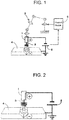
- the configuration of the robot system is schematically shown in FIG. 1 .
- the vertical articulated robot system will be outlined below.
- FIG. 1 is a diagram showing the configuration of a tracking system using a welding robot 5.
- the vertical articulated robot system includes the welding robot 5 and a control device 6 that is equipped with a teaching pendant (not shown).
- the welding robot 5 is a vertical articulated 6-axis industrial robot and is equipped with, at a tip, a welding tool including a welding torch 1 etc.
- the welding robot 5 may be mounted on a slider for moving it.
- the control device 6 controls the welding robot 5 according to a program about which the control device 6 has been taught in advance.
- the program is generated using a teaching pendant connected to the control device 6 or an offline teaching system that utilizes a personal computer. In either case, the program is generated in advance of an actual operation.
- the program generated by a personal computer is transferred to the control device 6 via a storage medium or the like or by a data communication.
- the arc-tracking welding method according to the embodiment is implemented in a form of a program provided in the control device 6.
- FIG. 2 is a schematic diagram showing arc welding.
- an arc is generated between a base material 4 and a welding wire 3 (consumable electrode) supplied from a welding torch 1 by applying a voltage between the welding wire 3 and the base material 4 by a welding power source 2.
- Welding is performed while the welding wire 3 and the base material 4 are melted by arc heat. Since the welding wire 3 melts down as arc welding is performed, during welding the welding wire 3 continues to be supplied from a supply device past the inside of the welding torch 1. That is, this arc welding is consumable electrode type welding.
- Welding metal produced by a molten portion of the base material 4 and the welding wire 3 solidifies to form a welding bead, whereby strong welding is attained.
- welding between medium-thickness plates as typified by welding between thick steel plates, to obtain necessary strength of a welded portion, it is necessary to set the width of a welding bead large and secure a necessary amount of deposited metal and penetration depth.
- welding is performed while an operation called weaving is performed in which the welding torch 1 is swung in the left-right direction.
- weaving is performed in which the welding torch 1 is swung in the left-right direction.
- the control device 6 outputs, to the welding robot 5, an instruction signal for a weaving operation of the welding torch 1.
- the welding power source 2 can output a desired, preprogrammed voltage waveform.
- the welding power source 2 can output a waveform on which a waveform having a prescribed frequency is superimposed.
- the power source 2 incorporates a voltage detector and a current detector (neither of which is shown), and the welding power source 2 can measure a voltage and a current that are output actually (i.e., welding voltage and welding current).
- the torch 1 also supplies a shield gas, whereby an arc column is protected from the air.
- Molten metal produced by welding is also protected from the air by virtue of the presence of gas that is generated by decomposition of flux contained in the welding wire 3, whereby formation of welding defects such as a blow hole is suppressed.
- the allowable deviation from a welding line in arc welding robots in the field of thick plates is smaller than 1 mm.
- Playback-type robots that perform welding at predetermined positions cannot attain welding quality of such a level. That is, in welding robots for medium-thickness plates, it is an essential condition to detect a deviation between a pre-taught welding position and a welding position of an actual work in real time by a deviation detector and tracking along a welding line is performed on the sub-millimeter order so as to adapt to every detected deviation. This is one of indispensable, very important functions required for such welding robots.
- FIG. 3A and FIG. 3B are explanatory diagrams illustrating the principle of arc-tracking schematically.
- the distance between the welding torch 1 and the base material 4 (hereinafter called a "torch height") varies depending on the weaving position.
- the welding current also varies depending on the weaving position as the torch height varies.
- the welding voltage also varies depending on the weaving position as the torch height varies.
- the welding current varies in a left-right symmetrical manner with respect to the weaving center B as shown in the figure and have the same value at both end positions (weaving end points) A and C of a weaving amplitude.
- the state that the welding current have the same value at the weaving end points A and C have the same value is a normal state.
- a difference occurs between welding currents at weaving end points A and C because of a torch height difference there.
- the arc-tracking is a function of following a welding line while detecting a current difference between end points and correcting a pre-taught weaving center.
- a program for calculating (estimating) such a deviation is installed in the control device 6 shown in FIG. 1 .
- a method for determining such a deviation will be described below.
- FIG. 4 shows a current waveform in a case where a constant-voltage welding power source 2 for arc welding is used.
- FIG. 4 shows a welding current waveform in a case where a weaving operation was performed with a period of 1 sec and an amplitude of 2 mm with the weaving center deviated from a welding line intentionally. Since the weaving center is always deviated by 2 mm, theoretically the difference between welding currents at the left and right ends should be constant. However, it is seen from FIG. 4 that the current waveform itself has a large current variation as compared with the difference between welding currents at the left and right ends, and that the current value varies greatly when a small phase deviation occurs between the left and right ends; that is, the SN ratio (signal-to-noise ratio) is very small.
- FIG. 5 shows a result of estimation of a resistance value R that is given by the following Equation (1) in which voltage information V was used in addition to the same current information I as shown in FIG. 4 that was obtained using the constant-voltage welding power source 2.
- V t R ⁇ I t
- FIG. 5 is a graph showing a resistance value estimation result using current and voltage waveforms obtained with the conventional constant-voltage welding power source. This figure, in which the resistance value varies to a large extent, does not contain useful information. Where the magnitude of the deviation is constant, theoretically the difference between resistance values at the left and right ends should remain constant. However, in FIG. 5 , the difference between resistance values at the left and right ends has a large variation. It is seen from FIG. 5 that a deviation from the welding line cannot be detected at all.
- the average of the resistance value which should be a positive value, has a negative value. This is due to a negative feedback control that to increase the stability of the welding the welding power source 2 decreases the voltage value as the current value increases (see FIG. 6 ).
- the average of the resistance value has a negative value because the negative feedback acts as if to have a negative resistance value.
- the conventional arc-tracking welding technique has the following problems:
- the embodiment employs a deviation detection method that uses the following technique and thereby enables accurate arc-tracking welding even in a welding site.
- the essence of this technique is to cause a welding current and a welding voltage supplied to a consumable electrode to include a high-frequency component, detect a resistance value variation resulting from an electrode height variation on the basis of a welding current and a welding voltage occurring during welding, and a deviation from a welding line is detected on the basis of the detected resistance value variation and left and right positions of weaving.
- the welding power source 2 is controlled so that a welding current and a welding voltage include a frequency component having a frequency higher than a weaving frequency. Furthermore, the detection accuracy of a resistance value variation is increased by setting the high-frequency component larger than a DC component of the welding current or welding voltage.
- One method for controlling the welding power source 2 so that a high-frequency component is included is to have a voltage instruction value or a voltage instruction value supplied to the welding power source 2 include a corresponding high-frequency component.
- Another method for controlling the welding power source 2 is that a pulse waveform is employed as a welding current and a welding voltage supplied to the consumable electrode, and a high-frequency component included in the pulse waveform is used as the above-mentioned high-frequency component,.
- the frequency of the high-frequency component is 100 Hz or higher.
- the technique of having a welding current or a welding voltage include a high-frequency waveform makes it possible to estimate a resistance value in a high-frequency range without being affected by a negative feedback control appearing in the constant voltage characteristic shown in FIG. 6 .
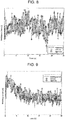
- Example 1 the welding power source 2 was caused to generate a current value on which a high-frequency waveform of 300 Hz was superimposed and a resistance value was estimated according to Equation (1). A result is shown in FIG. 7 .
- the waveform shown in FIG. 7 shows resistance values calculated according to Equation (1).
- Circular marks in FIG. 7 correspond to a state that the electrode tip is located at the end on the left side of a welding line (the left ends A in FIG. 3A and FIG. 3B ), and square marks in FIG. 7 correspond to a state that the electrode tip is located at the right end of a groove (the right ends C in FIG. 3A and FIG. 3B ).
- the meanings of circular marks and square marks to be used in drawings to be referred to below are the same as the above.
- a time point when the electrode tip is located at an end is recognized as a time point of an instruction to place the electrode tip at the end in a weaving instruction signal that the control device outputs to the robot plus an operation delay of the robot.
- R, L, and Vo can be estimated according to the following Equation (4) based on the relationship of the following Equation (3):
- R, L, and Vo thus estimated are averaged estimation values over an interval of t 1 to t n .
- the degree of smoothing and a pass frequency band can be changed by changing the averaging interval 1 to n.
- n since it is desired to pass the high-frequency waveform, it is appropriate to select n so as to pass the superimposed high-frequency waveform.
- the above method is such that one-shot type least squares estimation is performed every time
- the one-shot type method whereas estimation can be performed without being affected by past data before t 1 , the amount of calculation is large.
- the least squares method is advantageous in that the amount of calculation is very small though it is affected by past data to some extent.
- the estimation by the recursive least squares method is expressed by the following Equations (5): [Math.
- Pi is estimated values of [R, L, Vo] T of an ith recursive calculation.
- A(i,:) is an ith-row vector of the matrix A and, likewise, B(i,:) is an ith-row vector of the matrix B.
- ⁇ is a forgetting coefficient.
- the estimation result shown in FIG. 8 was obtained by the above recursive least squares method (the forgetting coefficient was given so as to be approximately equal to 0.1 sec).
- FIG. 7 Comparison between FIG. 7 (only R was estimated) and FIG. 8 (R, L, and Vo were estimated) does not produce a clear difference in noise level.
- FIG. 8 and FIG. 7 Enlarged versions of the graphs shown in FIG. 8 and FIG. 7 were drawn as FIG. 10 and FIG. 15 , respectively. It is seen from comparison between FIG. 15 (only R was estimated) and FIG. 10 (R, L, and Vo were estimated) that the result shown in FIG. 10 is clearly smaller in noise.
- Example 1 As described above, in Example 1, a high-frequency wave is superimposed and resistance values R are estimated on the basis of current and voltage waveforms without using a filter for eliminating the superimposed high-frequency component. It has become possible to increase the SN ratio by detecting a deviation from a welding line on the basis of the difference between resistance values at the left and right ends using resistance values thus estimated.
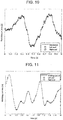
- FIG. 9 shows a result of detection of the difference between currents detected at the ends on the left and right of a welding line (Comparative Example).
- the current waveform shown in FIG. 9 was obtained by performing filtering processing for cutting the high-frequency component on the same current waveform as was used for determining the resistance values shown in FIG. 8 . This is because the high-frequency component only serves as noise. Differences between current values at the end points were compared with each other with compensation of phase deviations at the end points caused by the filter.
- FIG. 11 is an enlarged version of FIG. 9 .
- current value variations at locations other the end points are large for the differences between current values at the end points and hence there are pairs of end points where a useful current difference cannot be obtained.
- FIG. 10 is an enlarged version of FIG. 8 and shows a result of this Example. It is seen that resistance value variations at the end points in FIG. 10 are larger than in FIG. 11 and hence the case of FIG. 10 enables high-sensitivity detection of a deviation from a welding line.
- the current value increases as the torch height decreases and, conversely, the resistance value decreases as the torch height decreases. This means that deviation from a welding line is on the left side or the right side where the resistance value is smaller.
- Arc-tracking is enabled by correcting the torch position to the direction opposite to the deviation direction.
- Example 2 a pulse waveform is employed as an output current waveform of the welding power source 2 and a high-frequency component of the pulse waveform is used instead of superimposing a high-frequency component additionally.
- FIG. 12 shows a result of back calculation of a voltage V from estimation values of [R, L, Vo] T calculated by the sequential estimation according to Equations (5) in the above settings. It is seen that the actual voltage which includes a high-frequency component varies to a large extent because the current value is varied in pulse form and a voltage can be estimated with high accuracy by estimating the actual voltage using [R, L, Vo] T . On the other hand, it is seen that a resistance R can be estimated by the estimation according to Equation (1) which uses only the resistance value, like values of [R, L, Vo] T are estimated.
- JP-A-H05-177353 discloses a tracking technique using a neural network having a welding current waveform as an input. For example, tracking that is higher in accuracy than in the case of using the welding current can be realized by constructing a neural network based on a resistance value R waveform instead of a welding current waveform.
- the above-described arc-tracking welding method is suitable for welding with tracking that is performed by a welding robot.
- both of the estimation according to Equation (1) (only R is used) and the estimation according to Equation (2) (R, L, and Vo are used) require a high-frequency component that is higher in frequency than a control band of the welding power source 2. Also in the case of using a pulse waveform, when current and voltage values that are taken in by a robot controller are values obtained by eliminating noise (high-frequency components) by a lowpass filter, estimation of a resistance value R is difficult in a situation that a control is made so as to provide a constant voltage characteristic of FIG. 6 .
- the control device 6 for the robot samples welding currents and voltages from the welding power source 2.
- the sampling period is as long as several milliseconds to several tens of milliseconds and is not sufficiently short for the frequency of a pulse waveform that is output from the welding power source 2.
- sampling period is not sufficiently short, erroneous signal processing may be performed due to aliasing, for example.
- the sampling period needs to be sufficiently short for a pulse frequency (or the frequency of a superimposed high-frequency component).
- the sampling period needs to be such that the pulse frequency is sufficiently high as not to cause aliasing.
Landscapes
- Engineering & Computer Science (AREA)
- Physics & Mathematics (AREA)
- Plasma & Fusion (AREA)
- Mechanical Engineering (AREA)
- Butt Welding And Welding Of Specific Article (AREA)
- Arc Welding In General (AREA)
- Arc Welding Control (AREA)
Applications Claiming Priority (2)
| Application Number | Priority Date | Filing Date | Title |
|---|---|---|---|
| JP2016075181A JP6720452B2 (ja) | 2016-04-04 | 2016-04-04 | アーク倣い溶接方法 |
| PCT/JP2017/009826 WO2017175541A1 (fr) | 2016-04-04 | 2017-03-10 | Procédé de soudage de suivi d'arc et appareil de soudage de suivi d'arc |
Publications (2)
| Publication Number | Publication Date |
|---|---|
| EP3441176A1 true EP3441176A1 (fr) | 2019-02-13 |
| EP3441176A4 EP3441176A4 (fr) | 2019-12-11 |
Family
ID=60001077
Family Applications (1)
| Application Number | Title | Priority Date | Filing Date |
|---|---|---|---|
| EP17778920.3A Withdrawn EP3441176A4 (fr) | 2016-04-04 | 2017-03-10 | Procédé de soudage de suivi d'arc et appareil de soudage de suivi d'arc |
Country Status (6)
| Country | Link |
|---|---|
| US (1) | US11065704B2 (fr) |
| EP (1) | EP3441176A4 (fr) |
| JP (1) | JP6720452B2 (fr) |
| KR (1) | KR102090049B1 (fr) |
| CN (1) | CN108883487B (fr) |
| WO (1) | WO2017175541A1 (fr) |
Cited By (1)
| Publication number | Priority date | Publication date | Assignee | Title |
|---|---|---|---|---|
| EP3981536A1 (fr) * | 2020-10-12 | 2022-04-13 | Kabushiki Kaisha Kobe Seiko Sho (Kobe Steel, Ltd.) | Procédé de soudage avec suivi d'arc et dispositif de soudage |
Families Citing this family (9)
| Publication number | Priority date | Publication date | Assignee | Title |
|---|---|---|---|---|
| JP6339651B1 (ja) * | 2016-12-02 | 2018-06-06 | ファナック株式会社 | アーク溶接ロボットシステム |
| US11897060B2 (en) | 2017-11-29 | 2024-02-13 | Lincoln Global, Inc. | Systems and methods for welding torch weaving |
| US11065707B2 (en) * | 2017-11-29 | 2021-07-20 | Lincoln Global, Inc. | Systems and methods supporting predictive and preventative maintenance |
| CN108031953A (zh) * | 2017-12-04 | 2018-05-15 | 北京中电华强焊接工程技术有限公司 | 一种电弧跟踪大型曲面板角焊系统及方法 |
| US11027362B2 (en) * | 2017-12-19 | 2021-06-08 | Lincoln Global, Inc. | Systems and methods providing location feedback for additive manufacturing |
| JP7251988B2 (ja) * | 2019-01-22 | 2023-04-04 | 株式会社神戸製鋼所 | パルスアーク溶接の倣い制御方法、制御装置、溶接システム、溶接プログラム及び溶接電源 |
| JP7111666B2 (ja) * | 2019-08-07 | 2022-08-02 | 株式会社神戸製鋼所 | 可搬型溶接ロボットの溶接制御方法、溶接制御装置、可搬型溶接ロボット及び溶接システム |
| CN111843120B (zh) * | 2020-08-07 | 2022-01-07 | 北京时代科技股份有限公司 | 基于电弧传感和位置前馈的机器人焊缝跟踪算法 |
| CN119489240B (zh) * | 2023-08-15 | 2026-04-17 | 中国石油管道局工程有限公司 | 焊枪的控制方法、装置、设备及存储介质 |
Family Cites Families (13)
| Publication number | Priority date | Publication date | Assignee | Title |
|---|---|---|---|---|
| JPS59185575A (ja) * | 1983-04-06 | 1984-10-22 | Mitsubishi Electric Corp | 溶接線追従装置 |
| JPS60118377A (ja) * | 1983-11-30 | 1985-06-25 | Kobe Steel Ltd | 短絡移行ア−ク溶接における溶接ワイヤ突出長検出方法 |
| JPH09262675A (ja) * | 1996-03-28 | 1997-10-07 | Tokyo Gas Co Ltd | パイプ円周自動溶接装置の左右アーク倣い補正方法 |
| AT411340B (de) * | 1999-11-08 | 2003-12-29 | Fronius Schweissmasch Prod | Verfahren zum positionieren eines schweissbrenners im mittel eines schweissnahtsollverlaufes |
| AT410641B (de) * | 2000-04-05 | 2003-06-25 | Fronius Schweissmasch Prod | Verfahren zum fortlaufenden regeln bzw. nachführen einer position eines schweissbrenners bzw. eines schweisskopfes |
| JP5081134B2 (ja) | 2008-11-18 | 2012-11-21 | 株式会社ダイヘン | ロボット用アークセンサの倣いパラメータの設定方法、及びロボット用アークセンサの倣いパラメータの設定装置 |
| CN102615389B (zh) * | 2012-03-31 | 2014-08-27 | 上海交通大学 | 基于dsp的弧焊机器人摆动电弧跟踪系统和方法 |
| JP6038505B2 (ja) * | 2012-06-27 | 2016-12-07 | 八千代工業株式会社 | 開閉式天窓 |
| US20140001168A1 (en) * | 2012-06-27 | 2014-01-02 | Lincoln Global, Inc. | Parallel state-based controller for a welding power supply |
| CN102773588B (zh) * | 2012-08-04 | 2015-01-07 | 深圳市瑞凌实业股份有限公司 | 弧压跟踪脉冲埋弧焊控制方法、控制电路及焊机 |
| CN103447662B (zh) * | 2013-08-20 | 2015-04-15 | 江苏科技大学 | 窄间隙焊缝偏差的脉冲电弧传感检测方法 |
| WO2017163565A1 (fr) * | 2016-03-25 | 2017-09-28 | バンドー化学株式会社 | Matériau de polissage |
| JP2018185575A (ja) * | 2017-04-24 | 2018-11-22 | ヤフー株式会社 | 提供装置、提供方法、及び提供プログラム |
-
2016
- 2016-04-04 JP JP2016075181A patent/JP6720452B2/ja active Active
-
2017
- 2017-03-10 CN CN201780021721.2A patent/CN108883487B/zh active Active
- 2017-03-10 EP EP17778920.3A patent/EP3441176A4/fr not_active Withdrawn
- 2017-03-10 WO PCT/JP2017/009826 patent/WO2017175541A1/fr not_active Ceased
- 2017-03-10 KR KR1020187028271A patent/KR102090049B1/ko active Active
- 2017-03-10 US US16/090,803 patent/US11065704B2/en active Active
Cited By (2)
| Publication number | Priority date | Publication date | Assignee | Title |
|---|---|---|---|---|
| EP3981536A1 (fr) * | 2020-10-12 | 2022-04-13 | Kabushiki Kaisha Kobe Seiko Sho (Kobe Steel, Ltd.) | Procédé de soudage avec suivi d'arc et dispositif de soudage |
| KR20220048435A (ko) * | 2020-10-12 | 2022-04-19 | 가부시키가이샤 고베 세이코쇼 | 아크 트래킹 용접 방법 및 용접 장치 |
Also Published As
| Publication number | Publication date |
|---|---|
| CN108883487A (zh) | 2018-11-23 |
| KR102090049B1 (ko) | 2020-03-17 |
| JP2017185513A (ja) | 2017-10-12 |
| WO2017175541A1 (fr) | 2017-10-12 |
| JP6720452B2 (ja) | 2020-07-08 |
| US20200198041A1 (en) | 2020-06-25 |
| CN108883487B (zh) | 2021-02-23 |
| EP3441176A4 (fr) | 2019-12-11 |
| KR20180121944A (ko) | 2018-11-09 |
| US11065704B2 (en) | 2021-07-20 |
Similar Documents
| Publication | Publication Date | Title |
|---|---|---|
| US11065704B2 (en) | Arc-tracking welding method and arc-tracking welding apparatus | |
| EP0201641B1 (fr) | Système et procédé pour détecter la position d'un chalumeau de soudage | |
| US20120273473A1 (en) | Systems and methods to control gas tungsten arc welding and plasma arc welding | |
| KR102152049B1 (ko) | 아크 트래킹 용접에서의 어긋남양 검출 방법 | |
| JP2014030841A (ja) | アーク倣い溶接方法および溶接装置 | |
| EP3539707B1 (fr) | Dispositif d'affichage et procédé d'affichage de soudage à l'arc | |
| US11235414B2 (en) | Method of detecting amount of discrepancy in arc tracking welding | |
| KR101603919B1 (ko) | 위빙 용접 장치 및 용접선과 토치간 높이 제어 방법 | |
| US4785155A (en) | Automatic welding machine path correction system | |
| US12459048B2 (en) | Output control method for gas-shielded arc welding, welding system, welding power source, and welding control device | |
| US12186840B2 (en) | Pulse arc welding profile control method, control device, welding system, welding program, and welding power supply | |
| JP2002239728A (ja) | アーク溶接の制御方法及びアーク溶接装置 | |
| Cook et al. | Arc sensors in weld monitoring | |
| JPS61226181A (ja) | 自動溶接傚い装置における傚い制御方法 |
Legal Events
| Date | Code | Title | Description |
|---|---|---|---|
| STAA | Information on the status of an ep patent application or granted ep patent |
Free format text: STATUS: THE INTERNATIONAL PUBLICATION HAS BEEN MADE |
|
| PUAI | Public reference made under article 153(3) epc to a published international application that has entered the european phase |
Free format text: ORIGINAL CODE: 0009012 |
|
| STAA | Information on the status of an ep patent application or granted ep patent |
Free format text: STATUS: REQUEST FOR EXAMINATION WAS MADE |
|
| 17P | Request for examination filed |
Effective date: 20181004 |
|
| AK | Designated contracting states |
Kind code of ref document: A1 Designated state(s): AL AT BE BG CH CY CZ DE DK EE ES FI FR GB GR HR HU IE IS IT LI LT LU LV MC MK MT NL NO PL PT RO RS SE SI SK SM TR |
|
| AX | Request for extension of the european patent |
Extension state: BA ME |
|
| DAV | Request for validation of the european patent (deleted) | ||
| DAX | Request for extension of the european patent (deleted) | ||
| A4 | Supplementary search report drawn up and despatched |
Effective date: 20191111 |
|
| RIC1 | Information provided on ipc code assigned before grant |
Ipc: B23K 9/02 20060101ALI20191105BHEP Ipc: B23K 9/127 20060101AFI20191105BHEP Ipc: B23K 9/095 20060101ALI20191105BHEP Ipc: B23K 9/12 20060101ALI20191105BHEP |
|
| STAA | Information on the status of an ep patent application or granted ep patent |
Free format text: STATUS: EXAMINATION IS IN PROGRESS |
|
| 17Q | First examination report despatched |
Effective date: 20230215 |
|
| STAA | Information on the status of an ep patent application or granted ep patent |
Free format text: STATUS: THE APPLICATION HAS BEEN WITHDRAWN |
|
| 18W | Application withdrawn |
Effective date: 20230404 |