EP3441619B1 - Pompe centrifuge - Google Patents
Pompe centrifuge Download PDFInfo
- Publication number
- EP3441619B1 EP3441619B1 EP17185365.8A EP17185365A EP3441619B1 EP 3441619 B1 EP3441619 B1 EP 3441619B1 EP 17185365 A EP17185365 A EP 17185365A EP 3441619 B1 EP3441619 B1 EP 3441619B1
- Authority
- EP
- European Patent Office
- Prior art keywords
- sleeve
- clamping
- shaft
- centrifugal pump
- pump according
- Prior art date
- Legal status (The legal status is an assumption and is not a legal conclusion. Google has not performed a legal analysis and makes no representation as to the accuracy of the status listed.)
- Active
Links
Images



Classifications
-
- F—MECHANICAL ENGINEERING; LIGHTING; HEATING; WEAPONS; BLASTING
- F04—POSITIVE - DISPLACEMENT MACHINES FOR LIQUIDS; PUMPS FOR LIQUIDS OR ELASTIC FLUIDS
- F04D—NON-POSITIVE-DISPLACEMENT PUMPS
- F04D29/00—Details, component parts, or accessories
- F04D29/08—Sealings
- F04D29/10—Shaft sealings
- F04D29/106—Shaft sealings especially adapted for liquid pumps
-
- F—MECHANICAL ENGINEERING; LIGHTING; HEATING; WEAPONS; BLASTING
- F04—POSITIVE - DISPLACEMENT MACHINES FOR LIQUIDS; PUMPS FOR LIQUIDS OR ELASTIC FLUIDS
- F04D—NON-POSITIVE-DISPLACEMENT PUMPS
- F04D29/00—Details, component parts, or accessories
- F04D29/08—Sealings
- F04D29/10—Shaft sealings
-
- F—MECHANICAL ENGINEERING; LIGHTING; HEATING; WEAPONS; BLASTING
- F04—POSITIVE - DISPLACEMENT MACHINES FOR LIQUIDS; PUMPS FOR LIQUIDS OR ELASTIC FLUIDS
- F04D—NON-POSITIVE-DISPLACEMENT PUMPS
- F04D29/00—Details, component parts, or accessories
- F04D29/08—Sealings
- F04D29/10—Shaft sealings
- F04D29/12—Shaft sealings using sealing-rings
- F04D29/126—Shaft sealings using sealing-rings especially adapted for liquid pumps
-
- F—MECHANICAL ENGINEERING; LIGHTING; HEATING; WEAPONS; BLASTING
- F04—POSITIVE - DISPLACEMENT MACHINES FOR LIQUIDS; PUMPS FOR LIQUIDS OR ELASTIC FLUIDS
- F04D—NON-POSITIVE-DISPLACEMENT PUMPS
- F04D1/00—Radial-flow pumps, e.g. centrifugal pumps; Helico-centrifugal pumps
-
- F—MECHANICAL ENGINEERING; LIGHTING; HEATING; WEAPONS; BLASTING
- F04—POSITIVE - DISPLACEMENT MACHINES FOR LIQUIDS; PUMPS FOR LIQUIDS OR ELASTIC FLUIDS
- F04D—NON-POSITIVE-DISPLACEMENT PUMPS
- F04D1/00—Radial-flow pumps, e.g. centrifugal pumps; Helico-centrifugal pumps
- F04D1/06—Multi-stage pumps
-
- F—MECHANICAL ENGINEERING; LIGHTING; HEATING; WEAPONS; BLASTING
- F04—POSITIVE - DISPLACEMENT MACHINES FOR LIQUIDS; PUMPS FOR LIQUIDS OR ELASTIC FLUIDS
- F04D—NON-POSITIVE-DISPLACEMENT PUMPS
- F04D13/00—Pumping installations or systems
- F04D13/02—Units comprising pumps and their driving means
- F04D13/06—Units comprising pumps and their driving means the pump being electrically driven
-
- F—MECHANICAL ENGINEERING; LIGHTING; HEATING; WEAPONS; BLASTING
- F04—POSITIVE - DISPLACEMENT MACHINES FOR LIQUIDS; PUMPS FOR LIQUIDS OR ELASTIC FLUIDS
- F04D—NON-POSITIVE-DISPLACEMENT PUMPS
- F04D17/00—Radial-flow pumps, e.g. centrifugal pumps; Helico-centrifugal pumps
- F04D17/08—Centrifugal pumps
-
- F—MECHANICAL ENGINEERING; LIGHTING; HEATING; WEAPONS; BLASTING
- F04—POSITIVE - DISPLACEMENT MACHINES FOR LIQUIDS; PUMPS FOR LIQUIDS OR ELASTIC FLUIDS
- F04D—NON-POSITIVE-DISPLACEMENT PUMPS
- F04D25/00—Pumping installations or systems
- F04D25/02—Units comprising pumps and their driving means
- F04D25/06—Units comprising pumps and their driving means the pump being electrically driven
-
- F—MECHANICAL ENGINEERING; LIGHTING; HEATING; WEAPONS; BLASTING
- F04—POSITIVE - DISPLACEMENT MACHINES FOR LIQUIDS; PUMPS FOR LIQUIDS OR ELASTIC FLUIDS
- F04D—NON-POSITIVE-DISPLACEMENT PUMPS
- F04D29/00—Details, component parts, or accessories
- F04D29/40—Casings; Connections of working fluid
- F04D29/42—Casings; Connections of working fluid for radial or helico-centrifugal pumps
-
- F—MECHANICAL ENGINEERING; LIGHTING; HEATING; WEAPONS; BLASTING
- F04—POSITIVE - DISPLACEMENT MACHINES FOR LIQUIDS; PUMPS FOR LIQUIDS OR ELASTIC FLUIDS
- F04D—NON-POSITIVE-DISPLACEMENT PUMPS
- F04D29/00—Details, component parts, or accessories
- F04D29/40—Casings; Connections of working fluid
- F04D29/42—Casings; Connections of working fluid for radial or helico-centrifugal pumps
- F04D29/426—Casings; Connections of working fluid for radial or helico-centrifugal pumps especially adapted for liquid pumps
-
- F—MECHANICAL ENGINEERING; LIGHTING; HEATING; WEAPONS; BLASTING
- F04—POSITIVE - DISPLACEMENT MACHINES FOR LIQUIDS; PUMPS FOR LIQUIDS OR ELASTIC FLUIDS
- F04D—NON-POSITIVE-DISPLACEMENT PUMPS
- F04D29/00—Details, component parts, or accessories
- F04D29/60—Mounting; Assembling; Disassembling
- F04D29/62—Mounting; Assembling; Disassembling of radial or helico-centrifugal pumps
- F04D29/622—Adjusting the clearances between rotary and stationary parts
-
- F—MECHANICAL ENGINEERING; LIGHTING; HEATING; WEAPONS; BLASTING
- F04—POSITIVE - DISPLACEMENT MACHINES FOR LIQUIDS; PUMPS FOR LIQUIDS OR ELASTIC FLUIDS
- F04D—NON-POSITIVE-DISPLACEMENT PUMPS
- F04D29/00—Details, component parts, or accessories
- F04D29/60—Mounting; Assembling; Disassembling
- F04D29/62—Mounting; Assembling; Disassembling of radial or helico-centrifugal pumps
- F04D29/628—Mounting; Assembling; Disassembling of radial or helico-centrifugal pumps especially adapted for liquid pumps
-
- F—MECHANICAL ENGINEERING; LIGHTING; HEATING; WEAPONS; BLASTING
- F16—ENGINEERING ELEMENTS AND UNITS; GENERAL MEASURES FOR PRODUCING AND MAINTAINING EFFECTIVE FUNCTIONING OF MACHINES OR INSTALLATIONS; THERMAL INSULATION IN GENERAL
- F16J—PISTONS; CYLINDERS; SEALINGS
- F16J15/00—Sealings
- F16J15/16—Sealings between relatively-moving surfaces
- F16J15/34—Sealings between relatively-moving surfaces with slip-ring pressed against a more or less radial face on one member
- F16J15/3464—Mounting of the seal
- F16J15/348—Pre-assembled seals, e.g. cartridge seals
Definitions
- the invention relates to a single or multi-stage centrifugal pump with the features specified in the preamble of claim 1 and a mechanical cartridge seal for such a centrifugal pump according to the features specified in the preamble of claim 17.
- a sealing arrangement has a sliding ring rotating with the shaft and a counter sliding ring fixed to the housing, the sliding surfaces of which form a sealing gap, which is usually liquid-lubricated by the pump's delivery medium when the pump is in operation.
- the sliding ring and counter sliding ring are also sealed from the shaft or the pump housing via sealing rings.
- One of the rings of the mechanical seal is arranged to be axially displaceable and is subjected to spring force in order to keep the sealing gap as closed as possible and thus ensure the sealing function.
- Sitting on one there Sleeve is a clamping device that consists of two oppositely conical rings that are axially clamped together using screws and thus secure the sleeve on the shaft in a force-fitting manner.
- the sleeve is sealed from the shaft using O-rings.
- WO 2012/056650 A1 known mechanical seal unit which, however, is not designed as a cartridge seal but as a sealing arrangement divided in half, in which the sealing parts are held on the shaft by clamping forces that are generated by screwing the seal halves and positive engagement of radially arranged grub screws.
- the invention is based on the object of designing a generic centrifugal pump in such a way that the aforementioned disadvantages do not occur and of providing an appropriately designed mechanical seal cartridge seal for this purpose.
- the single or multi-stage centrifugal pump according to the invention has a pump housing with a shaft rotatably arranged therein, on which at least one impeller for conveying liquid is arranged in a rotationally fixed manner.
- the centrifugal pump has a mechanical cartridge seal which is arranged between the shaft and an opening in the pump housing through which the shaft is passed.
- the mechanical cartridge seal has a sleeve which surrounds the shaft at least in the area of the opening and which is releasably and non-rotatably connected to the shaft by means of a clamping device arranged on the outside of the sleeve via clamping means. It is provided that the clamping means or means of the clamping device only engage on the outside of the sleeve, in such a way that the sleeve is exclusively connected to the shaft in a non-positive manner.
- the basic idea is therefore to provide a clamping device with clamping means on the outside of the sleeve and to fix the sleeve on the shaft by clamping, i.e. in such a way that the sleeve exclusively is non-positively connected to the shaft and the sleeve is not penetrated by clamping means or the clamping means engage directly on the shaft. Because the clamping means engage on the outer cable of the sleeve, i.e. only act indirectly on the shaft, the surface of the shaft remains undamaged, so that even after the sliding cartridge seal has been replaced, the O-ring between the sleeve and the shaft can be moved along the shaft without this is damaged in its surface and thus in its sealing effect. Since the clamping means only engage on the outside of the sleeve, a centered fastening of the sleeve on the shaft is easy to achieve.
- the present invention is preferably applicable to single-stage or multi-stage centrifugal pumps of the inline design with a vertically arranged axis of rotation, but is not limited to this
- the clamping device is detachably connected to the sleeve, as is provided in a further development of the invention.
- the releasable connection of the clamping device with the sleeve creates the basic requirement for being able to dismantle the cartridge seal, so that it is possible to replace any worn seal rings, the spring or other components of the mechanical seal cartridge seal in order to repair or replace these components .
- This also makes it possible to investigate the cause of any leakage, since the components of the mechanical cartridge seal do not have to be cut for removal.
- the clamping device has at least two clamping components which surround the sleeve in sections and which are connected to one another via screws arranged preferably tangentially or parallel to it in such a way that clamping forces acting on the sleeve are exerted by tightening the screws via the clamping components be applied.
- the arrangement of at least two clamping components is expedient with regard to centering the clamping device to the shaft
- the screw connection between adjacent clamping components is advantageously designed such that the longitudinal axis of the screw is arranged perpendicular to a dividing plane of the clamping components to be connected, this dividing plane preferably being a radial dividing plane.
- the preferably two clamping components are designed identically.
- such a design can also be realized if three or more clamping components are provided. This reduces manufacturing and storage costs and simplifies assembly, as it ensures that only one type of clamping component can be installed.
- each clamping component has at least one clamping jaw intended to rest on the sleeve, which is preferably designed on its inside in such a way that it is adapted to the outer contour of the sleeve and/or the shaft. Then either a largely uniform load can take place over the entire circumference of the sleeve, which means that the clamping jaws can be supported over a correspondingly large area, or the sleeve can be deformed in such a way that the frictional connection between the sleeve and the shaft is only mediated over limited contact areas of the sleeve, whereby Higher contact pressures can be achieved between the sleeve and the shaft without damaging the shaft.
- the sleeve is preferably deformable by the clamping jaws, so that the inner contour of the sleeve at least partially conforms hugs the outer contour of the shaft.
- the inner contour of the sleeve is no longer exactly circular in cross section, but only forms limited contact areas of the sleeve on the circumference that nestle against the outer contour of the shaft to mediate the frictional connection with the shaft, where the clamping jaws act on the sleeve from the outside.
- the sleeve preferably has a first axial section and a second axial section, the clamping means of the clamping device only engaging on the outer contour of the first axial section of the sleeve.
- the known design of the mechanical cartridge seals can remain essentially unchanged in many parts, with the sleeve being extended by the first axial section compared to the known design in order to form an engagement surface for the clamping means of the clamping device encompassing the first axial section.
- the first axial section can have a slightly (e.g. 1-10%) widened inner contour at least at the end facing away from the second axial section in order to make it easier to use the shaft.
- each clamping component has a guide surface spaced apart from the sleeve, which is in operative connection with a counter-guide surface arranged on the adjacent clamping component, the guide surfaces lying in a plane which is parallel to the central longitudinal axis of the next adjacent screw, which has a clamping component connects to the adjacent clamping component, and / or lies parallel to a tangent to the sleeve or at an acute angle, preferably at an angle of up to 3 °.
- the arrangement of the guide surfaces at an acute angle of up to 3° The longitudinal axis of a screw, which connects a clamping component to the adjacent clamping component, has the advantage of an additional clamping effect in the transverse direction to the screw axis, with comparatively large forces being able to be applied due to the aforementioned flat angles.
- the arrangement and design of the clamping components is preferred such that the guide surfaces and the counter-guide surfaces are each arranged between a screw connecting two clamping components to one another and the outer circumference of the sleeve.
- Such a construction is space-saving and effective because the guidance takes place close to the sleeve and thus results in comparatively stiff clamping components.
- a guide surface and a counter-guide surface can each be formed on a guide pin and a recess receiving the pin.
- the guide surface then advantageously extends over the entire outer circumference of the pin, the counter-guiding surface around the entire inner circumference of the recess or, if necessary, only parts of the surfaces of the pin and recesses.
- Such an arrangement is particularly advantageous when providing two clamping components, which are preferably identically designed, then a pin is provided on each clamping component and a recess offset by approximately 180 ° with respect to the shaft axis, which interlock with each other in a form-fitting manner, so that the clamping components completely cover the sleeve enclose.
- a sufficient clamping effect which preferably only deforms the sleeve elastically and applies it to the shaft in a force-fitting manner, but, on the other hand, to apply a sufficient clamping force, it is advisable if one clamping jaw only extends over extends a comparatively small circumferential angle of the sleeve, between 30° and 50°, preferably between 40° and 45°.
- the values given are of course dependent on the number of clamping jaws arranged around the circumference and their width.
- a clamping component has, in addition to the clamping jaws extending over the above circumferential angle, a further contact surface which is provided for contacting the clamping component on the sleeve and which is circumferentially spaced from the clamping jaw.
- the further contact surface preferably serves to simplify the centering during assembly, ie the contact of the further contact surface on the sleeve can take place essentially without friction or only for a short time during assembly.
- a spaced area is advantageously provided between the clamping jaw and the further contact surface of the same clamping component, which extends over an angle between 80° and 110°, based on the circumference of the sleeve. Between the clamping jaw and the further contact surface of the clamping component, an area between 80° and 110° is advantageously provided, which is spaced apart from the sleeve.
- the at least one contact surface of a clamping jaw is advantageously arranged adjacent to a guide surface or counter-guide surface of the same clamping component, specifically away from it. This arrangement ensures that the screw connection between adjacent clamping jaws remains largely free of transverse forces.
- the arrangement of the clamping jaws is carried out circumferentially in such a way that the clamping forces acting on the sleeve are in the transverse direction to the longitudinal axis of the connecting screw are greater than the clamping forces directed in the longitudinal direction or parallel to the screw.
- the mechanical seal cartridge seal according to the invention for a centrifugal pump of the aforementioned type has a first sliding ring which is provided for rotationally fixed arrangement near a housing opening of the pump housing and which has an axial sliding and sealing surface which rests on an axial sliding and sealing surface of a second sliding ring, which is provided for rotationally fixed arrangement on a shaft passing through the housing opening.
- the sliding ring cartridges Seal has a sleeve and a clamping device arranged on the sleeve with clamping means, as well as spring means for applying axial force to the sliding and sealing surfaces to one another, and sealing means for sealing the sleeve against the shaft and for sealing on the housing side.
- the mechanical cartridge seal is designed in such a way that the clamping means(s) of the clamping device only engage on the outside of the sleeve, in such a way that the sleeve is only non-positively connected to the shaft.
- This arrangement is particularly advantageous because by fixing the mechanical cartridge seal on the shaft using the clamping device, there is no impairment of the surface of the shaft, so that when the seal is replaced, the sealing ring in the form of an O-ring, which is typically arranged between the sleeve and the shaft, can be pushed on, without the risk of damage.
- the clamping device has at least two clamping components which surround the sleeve in sections and which are connected to one another via screws in such a way that clamping forces acting on the sleeve are applied by tightening the screws via the clamping components, each clamping component having at least one for contact with the sleeve has a specific clamping jaw.
- the clamping device is advantageously arranged on the sleeve in a detachable manner, so that it is possible to dismantle the mechanical cartridge seal so that individual components of this seal can be exchanged, repaired or replaced.
- the pump shown is a multi-stage centrifugal pump 1 of the inline design with a vertical, ie upright, axis of rotation.
- the pump has, in a manner known per se, a foot 2 with which it stands on the floor and with which it can be attached to the floor.
- a cylindrical casing component 3 extends from the pump base 2 and is received at the top by a pump head 4 which has a motor chair 5, on the upper flange of which an electric motor 6 is attached.
- the foot 2 has a first connecting flange 7 of a suction line and a second connecting flange 8 of a pressure line arranged on the same axis on the other side.
- Pump stages are arranged within the area of the jacket 3, each consisting of a centrifugal wheel 10 and an adjoining guide device, so that the liquid entering the pump housing through the suction line on the first connecting flange 7 passes through the pump stages from bottom to top with an increase in pressure, the output of which Last stage via an annular channel, the inner wall of which is formed by the outer wall of the guide apparatus and the outer wall of which is formed by the jacket 3, back into the foot 7 and there to the pressure line on the second connecting flange 8.
- the guide apparatus and the jacket 3 are Clamped between pump head 4 and pump base 2 using four tie rods 9.
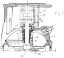
- the shaft passage through the pump head 4 is realized by means of a mechanical cartridge seal 13, the structure of which is detailed in the Figures 3-5 is visible.
- the mechanical cartridge seal 13 has a carrier 14, which is annular and has an external thread 15, with which it is fixed in a corresponding internal thread of an opening 16 of the pump housing, in particular of the pump head 4, incorporating an O-ring 17.
- a flange 18 of the carrier 14 rests on the top of the pump head 4 surrounding the opening 16.
- a stationary slide ring 20 is fixed in a rotationally fixed manner by incorporating an O-ring 19, the underside of which forms the actual sliding and axial sealing surface and on which the top of a rotating slide ring 21 rests as a counter surface, which is rotationally fixed but axially movable on one of the shafts 11 sits in the area of the housing opening 16 surrounding sleeve 22, which is connected to the shaft 11 in a rotationally fixed manner.
- the sleeve 22 is sealed from the shaft 11 by means of an O-ring 23, the O-ring 23 sits within a ring 24 which is firmly connected to the sleeve 22 and which has two diametrically arranged drivers 25 which extend from the top of the ring 24 extend at the top and sit in engagement with corresponding recesses 26 in a ring 27, which is connected in a rotationally fixed manner to the rotating slide ring 21 and supports it axially via a helical spring 28 arranged between the rings 24 and 27.
- An O-ring 40 is integrated between the rotating seal ring 21, the ring 27 and the sleeve 22, which is located axially on the side of the seal ring 21 facing away from the sliding surface, and facing away opposite in an upward direction open groove-like recess of the ring 27 and rests radially on the inside of the sleeve 22.
- the structure of the mechanical cartridge seal 13 largely corresponds to well-known mechanical cartridge seals such as those installed in Grundfos pumps of the CR type, to which reference is made in this regard.
- the sliding ring cartridge seal 13 is fastened on the housing side by means of the carrier 14.
- the sleeve 22 is fastened on the shaft side by means of a clamping device 29, which surrounds the sleeve 22 in a ring shape and has two identically designed clamping components 30, which are connected to one another by means of two screws 31 and on the sleeve 22 are firmly fixed.
- the force is so high that the sleeve 22 is elastically deformed in the area of the clamping device 29 and is pressed non-positively onto the shaft 11, so that a non-positive connection occurs in both the axial and rotational directions.
- the clamping device 29 is fixed non-positively on the sleeve 22 and this is fixed non-positively on the shaft 11.
- the sleeve 22 protrudes Fig. 3 with an upper first axial section 22a out of the carrier 15 and is only surrounded by the clamping device 29 in this upper first axial section 22a.
- a lower second axial section 22b is encompassed by the carrier 14.
- the upper end 22c of the first axial section 22a of the sleeve 22, which is remote from the second axial section 22b, has a slightly (eg 1-10%) widened inner contour.
- the clamping components 30 have clamping jaws 32 which are adapted to the outer contour of the sleeve 22 and rest against it. These clamping jaws extend over an angle a of the circumference of the sleeve 22 of 43° and are arranged diametrically to one another. Seen in the circumferential direction, a clamping jaw 32 is connected to one Clamping component 30 has an area over an angle ⁇ of 95 °, which is formed at a distance from the sleeve 22, after which a further contact surface 33 follows as a support surface, which, however, only extends over a few degrees of the circumference. This results in a circumferential extension of approximately 170° for each clamping component 30, so that a free space of a few degrees remains at the ends.
- contact surfaces are formed via the support surfaces 33 and the clamping jaws 32; the force is applied by means of the screws 31, the longitudinal axes 34 of which are arranged perpendicular to a radial dividing plane 35 and parallel to tangents of the sleeve 22.
- the clamping jaws 32 and the supporting surfaces 33 are arranged near the dividing plane 35 and each clamping jaw 32 lies away from the sliding surface 36 of the same clamping component 30.
- the sliding surfaces 36 lie tangentially or parallel to it and parallel to the axes 34 of the screws 31; they have counter-sliding surfaces 37 in contact.
- These pairs of sliding surfaces 36 and counter-sliding surfaces 37 form guides and determine the direction in which the clamping components 30 can be moved towards one another. They ensure that the screws 31 are kept largely free of transverse forces and, together with the clamping jaws 32, form structures which are approximately wedge-shaped in cross section, which ensure that transverse forces are generated on the sleeve 22 when the clamping components 30 move towards one another, i.e.
- the sliding and counter-sliding surfaces can also each be formed by a pin and a recess provided as a counterpart, in which case the clamping component then has a pin on one side and a recess on the other side, so that In each case a peripheral surface of the pin forms a sliding surface and an inner peripheral surface of the recess forms a counter-sliding surface.
- the clamping device 29 is formed by two identical clamping components 30 and two screws 31, the screws resting with their heads on a head support surface of the clamping component 30, are guided through a hole-like recess 38 and are fixed in a blind hole 39 provided with an internal thread .
- the mechanical cartridge seal 13 is pushed over the free end of the shaft 11 and fixed in the opening 16 of the pump housing by screwing in the carrier 14.
- the clamping device 29 is also pushed from above over the shaft 11 until the clamping device 29 rests loosely on the top of the carrier 14.
- the screws 31 are then tightened evenly and with a predetermined torque, after which the clamping device 29 is non-positively fastened to the sleeve 22 in such a way that the sleeve 22 is elastically deformed towards the shaft 11 and is also non-positively fixed there.
- the mechanical cartridge seal 13 can, if necessary, be removed again in the reverse order. Since the clamping device 29 is only non-positively connected to the sleeve 22, the entire mechanical cartridge seal 13 can be taken apart and, if necessary, repaired by replacing worn parts. Since the sleeve 22 only has a friction fit on the shaft 11 has applied, the surface of the shaft 11 has remained intact, so that the O-ring 23, which seals the sleeve 22 from the shaft 11, cannot be damaged either during disassembly or during assembly of the mechanical cartridge seal 13.
Landscapes
- Engineering & Computer Science (AREA)
- General Engineering & Computer Science (AREA)
- Mechanical Engineering (AREA)
- Structures Of Non-Positive Displacement Pumps (AREA)
Claims (18)
- Pompe centrifuge à un ou plusieurs étage(s) avec un carter de pompe (2 à 5) et un arbre (11) agencé de manière rotative dans celui-ci, avec au moins une roue centrifuge (10) agencée de manière solidaire en rotation sur l'arbre (11) pour le transport de liquide, avec une garniture mécanique à cartouche (13) agencée entre l'arbre (11) et un orifice (16), à travers lequel l'arbre (11) passe, du carter (2 à 5), la garniture mécanique à cartouche (13) comprenant un manchon (22) qui entoure l'arbre (11) au moins dans la région de l'orifice (16) et qui est relié de manière amovible et solidaire en rotation à l'arbre (11) moyennant un dispositif de serrage (29) agencé sur la face extérieure du manchon (22) et par l'intermédiaire de moyens de serrage (32), le ou les moyen(s) de serrage (32) du dispositif de serrage (29) ne venant en prise qu'à la face extérieure du manchon (22), de telle manière que le manchon (22) ne soit relié à l'arbre (11) que par complémentarité de force, caractérisée en ce que le dispositif de serrage (29) comprend au moins deux composants de serrage (30) entourant le manchon (22) par sections et reliés les uns aux autres par l'intermédiaire de vis (31) de telle manière que des forces de serrage agissant sur le manchon (22) par l'intermédiaire des composants de serrage (30) soient appliquées par serrage des vis (31), chaque composant de serrage (30) comprenant au moins une mâchoire de serrage (32) destinée à être mise en en appui sur le manchon (22).
- Pompe centrifuge selon la revendication 1, caractérisée en ce que le dispositif de serrage (29) est relié de manière amovible au manchon (22).
- Pompe centrifuge selon la revendication 1 ou 2, caractérisée en ce que les vis (31) sont agencées de manière préférée tangentiellement ou parallèlement aux composants de serrage.
- Pompe centrifuge selon la revendication 3, caractérisée en ce qu'une vis (31) reliant l'un à l'autre deux composants de serrage (30) voisins est agencée perpendiculairement à un plan de division (35), de manière préférée radial, des composants de serrage (30) à relier.
- Pompe centrifuge selon l'une quelconque des revendications précédentes, caractérisée en ce que les, de manière préférée deux, composants de serrage (30) sont réalisés de manière identique.
- Pompe centrifuge selon l'une quelconque des revendications précédentes, caractérisée en ce qu'une mâchoire de serrage (32) est adaptée au contour extérieur du manchon (22) et/ou de l'arbre (11).
- Pompe centrifuge selon la revendication 6, caractérisée en ce que le manchon (22) peut être au moins partiellement déformé par la mâchoire de serrage (32), de sorte que le contour intérieur du manchon (22) épouse au moins partiellement le contour extérieur de l'arbre (11).
- Pompe centrifuge selon l'une quelconque des revendications précédentes, caractérisée en ce que le manchon (22) comprend une première section axiale (22a) et une seconde section axiale (22b), les moyens de serrage (32) du dispositif de serrage (29) ne venant en prise qu'à la face extérieure de la première section axiale (22a) du manchon (22).
- Pompe centrifuge selon l'une quelconque des revendications précédentes, caractérisée en ce que chaque composant de serrage (30) comprend une surface de guidage (36) espacée par rapport au manchon (22) et en liaison active avec une surface de contre-guidage (37) agencée sur le composant de serrage (30) voisin, les surfaces de guidage (36, 37) se trouvant dans un plan parallèle à l'axe longitudinal médian (34) de la vis (31) voisine la plus proche et/ou parallèle à une tangente au manchon (22) ou ayant un angle aigu, de manière préférée un angle allant jusqu'à 5°, par rapport à celle-ci.
- Pompe centrifuge selon la revendication 9, caractérisée en ce que les surfaces de guidage (36) et les surfaces de contre-guidage (37) sont agencées respectivement entre une vis (31) reliant deux composants de serrage (30), et la périphérie extérieure du manchon (22).
- Pompe centrifuge selon la revendication 9 ou 10, caractérisée en ce qu'une surface de guidage et une surface de contre-guidage sont formées sur une cheville de guidage et un évidement accueillant la cheville.
- Pompe centrifuge selon l'une quelconque des revendications précédentes, caractérisée en ce qu'une mâchoire de serrage (32) s'étend sur un angle inscrit (a) du manchon (22) compris entre 30° et 50°, de manière préférée compris entre 40° et 45°.
- Pompe centrifuge selon l'une quelconque des revendications précédentes, caractérisée en ce qu'un composant de serrage (30) comprend une surface de mise en place (33) supplémentaire destinée à la mise en place du composant de serrage (30) sur le manchon (22) et périphériquement espacée par rapport à la mâchoire de serrage (32).
- Pompe centrifuge selon la revendication 13, caractérisée en ce que le composant de serrage (30) comprend entre la mâchoire de serrage (32) et la surface de mise en place (33) supplémentaire une région espacée par rapport au manchon (22) et s'étendant sur une plage angulaire (β) comprise entre 80° et 110°.
- Pompe centrifuge selon l'une quelconque des revendications précédentes, caractérisée en ce que ladite au moins une surface de mise en place d'une mâchoire de serrage (32) est agencée au voisinage d'une surface de guidage (36) du même composant de serrage (30) et en s'en détournant.
- Pompe centrifuge selon l'une quelconque des revendications précédentes, caractérisée en ce que l'agencement des mâchoires de serrage (32) est réalisé de manière périphérique de sorte que les forces de serrage agissant sur le manchon (22) dans la direction transversale à l'axe longitudinal (34) de la vis de liaison (31) soient supérieures aux forces de serrage orientées dans la direction longitudinale ou parallèlement à la vis (31).
- Garniture mécanique à cartouche pour une pompe centrifuge selon l'une quelconque des revendications précédentes, avec une première bague de glissement (20) destinée à être agencée de manière solidaire en rotation à proximité d'un orifice de carter (16) d'un carter de pompe (2 à 5) et comprenant une surface axiale de glissement et d'étanchéité qui repose sur une surface axiale de glissement et d'étanchéité d'une seconde bague de glissement (21) destinée à être agencée de manière solidaire en rotation sur un arbre (11) traversant l'orifice de carter (16), avec un manchon (22) et avec un dispositif de serrage (29) agencé sur le manchon (22) avec des moyens de serrage (32), avec des moyens de ressort (28) permettant l'exercice axial réciproque de forces entre les surfaces de glissement et d'étanchéité, ainsi qu'avec des moyens d'étanchéité (17, 19, 23), le ou les moyen(s) de serrage (32) du dispositif de serrage (29) ne venant en prise qu'à la face extérieure du manchon (22), de telle manière que le manchon (22) ne soit relié à l'arbre (11) que par complémentarité de force, caractérisé en ce que le dispositif de serrage (29) comprend au moins deux composants de serrage (30) entourant le manchon (22) par sections et reliés entre eux par des vis (31) de telle manière que des forces de serrage agissant sur le manchon (22) par l'intermédiaire des composants de serrage (30) soient appliquées par serrage des vis (31), chaque composant de serrage (30) comprenant au moins une mâchoire de serrage (32) destinée à venir en place sur le manchon (22).
- Garniture mécanique à cartouche selon la revendication 17, ayant des caractéristiques selon l'une quelconque ou plusieurs des revendications 2 à 16.
Priority Applications (3)
| Application Number | Priority Date | Filing Date | Title |
|---|---|---|---|
| EP17185365.8A EP3441619B1 (fr) | 2017-08-08 | 2017-08-08 | Pompe centrifuge |
| US16/056,903 US10941784B2 (en) | 2017-08-08 | 2018-08-07 | Centrifugal pump |
| CN201810896424.9A CN109386496A (zh) | 2017-08-08 | 2018-08-08 | 离心泵 |
Applications Claiming Priority (1)
| Application Number | Priority Date | Filing Date | Title |
|---|---|---|---|
| EP17185365.8A EP3441619B1 (fr) | 2017-08-08 | 2017-08-08 | Pompe centrifuge |
Publications (2)
| Publication Number | Publication Date |
|---|---|
| EP3441619A1 EP3441619A1 (fr) | 2019-02-13 |
| EP3441619B1 true EP3441619B1 (fr) | 2023-11-01 |
Family
ID=59569211
Family Applications (1)
| Application Number | Title | Priority Date | Filing Date |
|---|---|---|---|
| EP17185365.8A Active EP3441619B1 (fr) | 2017-08-08 | 2017-08-08 | Pompe centrifuge |
Country Status (3)
| Country | Link |
|---|---|
| US (1) | US10941784B2 (fr) |
| EP (1) | EP3441619B1 (fr) |
| CN (1) | CN109386496A (fr) |
Families Citing this family (6)
| Publication number | Priority date | Publication date | Assignee | Title |
|---|---|---|---|---|
| TWI696763B (zh) | 2019-04-11 | 2020-06-21 | 大井泵浦工業股份有限公司 | 直立式泵浦結構 |
| CN110821880B (zh) * | 2019-11-11 | 2025-07-25 | 江苏金海钰龙流体科技有限公司 | 一种强制传动双端面集装式机械密封 |
| EP3961039B1 (fr) * | 2020-08-31 | 2024-10-02 | Sulzer Management AG | Pompe permettant de transporter un fluide |
| USD1093433S1 (en) * | 2023-06-06 | 2025-09-16 | Fujian Snowman Compressor Co., Ltd | Screw compressor |
| USD1117350S1 (en) * | 2023-06-06 | 2026-03-10 | Fujian Snowman Compressor Co., Ltd | Screw compressor |
| USD1102483S1 (en) * | 2023-09-27 | 2025-11-18 | Fujian Snowman Compressor Co., Ltd | Screw compressor |
Citations (1)
| Publication number | Priority date | Publication date | Assignee | Title |
|---|---|---|---|---|
| WO2012056650A1 (fr) * | 2010-10-29 | 2012-05-03 | 株式会社タンケンシールセーコウ | Joint mécanique |
Family Cites Families (22)
| Publication number | Priority date | Publication date | Assignee | Title |
|---|---|---|---|---|
| US1888957A (en) * | 1929-12-16 | 1932-11-22 | Chain Belt Co | Sealing gland |
| US2429953A (en) * | 1945-11-28 | 1947-10-28 | Sealol Corp | Shaft seal assembly |
| ZA831964B (en) * | 1982-04-02 | 1984-11-28 | Flexibox Ltd | Mechanical seals |
| US4746268A (en) * | 1987-07-29 | 1988-05-24 | Hitachi, Ltd. | End face mechanical shaft seal for use in hydraulic machines and seal ring assembly for use in the shaft seal |
| AU2551188A (en) | 1987-10-02 | 1989-04-18 | Durametallic Corporation | Mechanical seal |
| GB9121565D0 (en) * | 1991-10-10 | 1991-11-27 | Aes Eng Ltd | Mechanical seals |
| US5294132A (en) * | 1992-07-24 | 1994-03-15 | Five Star Seal Corporation | Semi-cartridge seal |
| JP2684016B2 (ja) | 1994-08-10 | 1997-12-03 | フクシロ工業株式会社 | 完全分割型メカニカルシール |
| US6357753B1 (en) * | 1999-03-16 | 2002-03-19 | Nippon Pillar Packing Co., Ltd. | Cartridge-type mechanical seal |
| US20040201176A1 (en) * | 1999-07-27 | 2004-10-14 | Bjornson Carl C. | Mechanical split seal |
| US6685191B2 (en) * | 2000-02-11 | 2004-02-03 | A. W. Chesterton Company | Mechanical seal for rotating shaft |
| CN2428667Y (zh) | 2000-06-13 | 2001-05-02 | 刘宝全 | 管接头接固新结构 |
| CA2331146A1 (fr) | 2001-01-16 | 2002-07-16 | Hydro Incorporated | Equipement de joint de pompe resistant aux acides |
| DE10106978A1 (de) * | 2001-02-15 | 2002-09-05 | Grundfos As | Einbaufertige Gleitringdichtung für die Welle einer Pumpe |
| FR2915537B1 (fr) | 2007-04-24 | 2012-07-20 | Caillau Ets | Dispositif de serrage |
| CN101586666A (zh) | 2009-06-30 | 2009-11-25 | 蒋敏 | 防涡流耐磨机械密封 |
| DE112013000924B4 (de) * | 2012-02-10 | 2021-07-29 | Orion Engineered Seals, Llc | Labyrinthdichtung |
| CN102606484A (zh) * | 2012-03-27 | 2012-07-25 | 上海阿波罗机械股份有限公司 | 一种核电站用的上充泵 |
| CN202691353U (zh) | 2012-05-31 | 2013-01-23 | 宁波市江北保隆消声系统制造有限公司 | 一种v型卡箍 |
| CN202812546U (zh) | 2012-08-31 | 2013-03-20 | 天津连兴金属制品有限公司 | 一种管道用卡箍 |
| JP5999770B2 (ja) | 2013-03-09 | 2016-09-28 | イーグル工業株式会社 | 分割型メカニカルシール |
| JP6353778B2 (ja) | 2014-12-11 | 2018-07-04 | 株式会社酉島製作所 | メカニカルシールの支持装置 |
-
2017
- 2017-08-08 EP EP17185365.8A patent/EP3441619B1/fr active Active
-
2018
- 2018-08-07 US US16/056,903 patent/US10941784B2/en not_active Expired - Fee Related
- 2018-08-08 CN CN201810896424.9A patent/CN109386496A/zh active Pending
Patent Citations (1)
| Publication number | Priority date | Publication date | Assignee | Title |
|---|---|---|---|---|
| WO2012056650A1 (fr) * | 2010-10-29 | 2012-05-03 | 株式会社タンケンシールセーコウ | Joint mécanique |
Also Published As
| Publication number | Publication date |
|---|---|
| EP3441619A1 (fr) | 2019-02-13 |
| US10941784B2 (en) | 2021-03-09 |
| US20190048885A1 (en) | 2019-02-14 |
| CN109386496A (zh) | 2019-02-26 |
Similar Documents
| Publication | Publication Date | Title |
|---|---|---|
| EP3441619B1 (fr) | Pompe centrifuge | |
| DE19728498A1 (de) | Pumpe | |
| EP3812546A1 (fr) | Pompe à broche hélicoïdale | |
| EP3112065B1 (fr) | Dispositif mecanique, en particulier dispositif de fraisage | |
| DE102006062240B4 (de) | Lösbare Kupplung | |
| DE102014211412B3 (de) | Werkzeugaufnahme mit Kühlmittelzufuhr hinter Nutenstein | |
| DE2614834A1 (de) | Vorrichtung zum zusammenkuppeln von motoren | |
| EP2707629B1 (fr) | Dispositif d'étanchéification d'une chambre de pompage d'une pompe à piston tournant, et pompe à piston tournant dotée de ce dispositif | |
| EP0013942B1 (fr) | Pompe centrifuge pour liquides contenant des matières solides | |
| DE102008000737A1 (de) | Handwerkzeugmaschine, insbesondere handgeführte Schleifmaschine | |
| DE1288386B (de) | Zylindrisches Gehaeuse fuer oszillierende Drehkolbenmaschinen | |
| EP2992214B1 (fr) | Arbre de pompe | |
| DE102015106614A1 (de) | Pumpenvorrichtung | |
| DE102015007567B4 (de) | Rotoranschlussvorrichtung | |
| EP2626571B1 (fr) | Bague de serrage dotée d'une limitation de force | |
| WO2009115142A1 (fr) | Machine-outil à main, en particulier meuleuse à main | |
| EP2818722B1 (fr) | Pompe centrifuge | |
| DE1575805B1 (de) | Mehrteiliger loesbarer Anschlagring fuer eine Welle | |
| EP3171033A1 (fr) | Pompe centrifuge à étages multiples avec ouverture de carter pour la maintenance d'un piston d'équilibrage de poussée axiale | |
| BE1031383B1 (de) | Kreiselpumpe, insbesondere Bohrlochpumpe | |
| DE20305562U1 (de) | Klemmverbindung für eine fliegend auf einer Motorwelle gelagerte Pumpenwelle | |
| EP3171028B1 (fr) | Pompe centrifuge multicellulaire avec un piston d'équilibrage de poussée axiale dont les faces de haute et basse pression sont séparées par une garniture mécanique | |
| DE2901638C3 (fr) | ||
| WO2023194182A1 (fr) | Dispositif d'étanchéité mécanique de face d'extrémité, joint d'étanchéité mécanique de face d'extrémité et procédé de montage de dispositif d'étanchéité mécanique de face d'extrémité | |
| DE202013104369U1 (de) | Kreiselpumpe mit hydraulisch gespannter Pumpenwelle |
Legal Events
| Date | Code | Title | Description |
|---|---|---|---|
| PUAI | Public reference made under article 153(3) epc to a published international application that has entered the european phase |
Free format text: ORIGINAL CODE: 0009012 |
|
| STAA | Information on the status of an ep patent application or granted ep patent |
Free format text: STATUS: THE APPLICATION HAS BEEN PUBLISHED |
|
| AK | Designated contracting states |
Kind code of ref document: A1 Designated state(s): AL AT BE BG CH CY CZ DE DK EE ES FI FR GB GR HR HU IE IS IT LI LT LU LV MC MK MT NL NO PL PT RO RS SE SI SK SM TR |
|
| AX | Request for extension of the european patent |
Extension state: BA ME |
|
| STAA | Information on the status of an ep patent application or granted ep patent |
Free format text: STATUS: REQUEST FOR EXAMINATION WAS MADE |
|
| 17P | Request for examination filed |
Effective date: 20190812 |
|
| RBV | Designated contracting states (corrected) |
Designated state(s): AL AT BE BG CH CY CZ DE DK EE ES FI FR GB GR HR HU IE IS IT LI LT LU LV MC MK MT NL NO PL PT RO RS SE SI SK SM TR |
|
| STAA | Information on the status of an ep patent application or granted ep patent |
Free format text: STATUS: EXAMINATION IS IN PROGRESS |
|
| 17Q | First examination report despatched |
Effective date: 20210930 |
|
| GRAP | Despatch of communication of intention to grant a patent |
Free format text: ORIGINAL CODE: EPIDOSNIGR1 |
|
| STAA | Information on the status of an ep patent application or granted ep patent |
Free format text: STATUS: GRANT OF PATENT IS INTENDED |
|
| INTG | Intention to grant announced |
Effective date: 20230126 |
|
| GRAJ | Information related to disapproval of communication of intention to grant by the applicant or resumption of examination proceedings by the epo deleted |
Free format text: ORIGINAL CODE: EPIDOSDIGR1 |
|
| STAA | Information on the status of an ep patent application or granted ep patent |
Free format text: STATUS: EXAMINATION IS IN PROGRESS |
|
| INTC | Intention to grant announced (deleted) | ||
| GRAP | Despatch of communication of intention to grant a patent |
Free format text: ORIGINAL CODE: EPIDOSNIGR1 |
|
| STAA | Information on the status of an ep patent application or granted ep patent |
Free format text: STATUS: GRANT OF PATENT IS INTENDED |
|
| INTG | Intention to grant announced |
Effective date: 20230621 |
|
| GRAS | Grant fee paid |
Free format text: ORIGINAL CODE: EPIDOSNIGR3 |
|
| GRAA | (expected) grant |
Free format text: ORIGINAL CODE: 0009210 |
|
| STAA | Information on the status of an ep patent application or granted ep patent |
Free format text: STATUS: THE PATENT HAS BEEN GRANTED |
|
| AK | Designated contracting states |
Kind code of ref document: B1 Designated state(s): AL AT BE BG CH CY CZ DE DK EE ES FI FR GB GR HR HU IE IS IT LI LT LU LV MC MK MT NL NO PL PT RO RS SE SI SK SM TR |
|
| REG | Reference to a national code |
Ref country code: GB Ref legal event code: FG4D Free format text: NOT ENGLISH |
|
| REG | Reference to a national code |
Ref country code: CH Ref legal event code: EP |
|
| REG | Reference to a national code |
Ref country code: IE Ref legal event code: FG4D Free format text: LANGUAGE OF EP DOCUMENT: GERMAN |
|
| REG | Reference to a national code |
Ref country code: DE Ref legal event code: R096 Ref document number: 502017015546 Country of ref document: DE |
|
| REG | Reference to a national code |
Ref country code: LT Ref legal event code: MG9D |
|
| REG | Reference to a national code |
Ref country code: NL Ref legal event code: MP Effective date: 20231101 |
|
| PG25 | Lapsed in a contracting state [announced via postgrant information from national office to epo] |
Ref country code: GR Free format text: LAPSE BECAUSE OF FAILURE TO SUBMIT A TRANSLATION OF THE DESCRIPTION OR TO PAY THE FEE WITHIN THE PRESCRIBED TIME-LIMIT Effective date: 20240202 |
|
| PG25 | Lapsed in a contracting state [announced via postgrant information from national office to epo] |
Ref country code: IS Free format text: LAPSE BECAUSE OF FAILURE TO SUBMIT A TRANSLATION OF THE DESCRIPTION OR TO PAY THE FEE WITHIN THE PRESCRIBED TIME-LIMIT Effective date: 20240301 |
|
| PG25 | Lapsed in a contracting state [announced via postgrant information from national office to epo] |
Ref country code: LT Free format text: LAPSE BECAUSE OF FAILURE TO SUBMIT A TRANSLATION OF THE DESCRIPTION OR TO PAY THE FEE WITHIN THE PRESCRIBED TIME-LIMIT Effective date: 20231101 |
|
| PG25 | Lapsed in a contracting state [announced via postgrant information from national office to epo] |
Ref country code: NL Free format text: LAPSE BECAUSE OF FAILURE TO SUBMIT A TRANSLATION OF THE DESCRIPTION OR TO PAY THE FEE WITHIN THE PRESCRIBED TIME-LIMIT Effective date: 20231101 |
|
| PG25 | Lapsed in a contracting state [announced via postgrant information from national office to epo] |
Ref country code: ES Free format text: LAPSE BECAUSE OF FAILURE TO SUBMIT A TRANSLATION OF THE DESCRIPTION OR TO PAY THE FEE WITHIN THE PRESCRIBED TIME-LIMIT Effective date: 20231101 |
|
| PG25 | Lapsed in a contracting state [announced via postgrant information from national office to epo] |
Ref country code: NL Free format text: LAPSE BECAUSE OF FAILURE TO SUBMIT A TRANSLATION OF THE DESCRIPTION OR TO PAY THE FEE WITHIN THE PRESCRIBED TIME-LIMIT Effective date: 20231101 Ref country code: LT Free format text: LAPSE BECAUSE OF FAILURE TO SUBMIT A TRANSLATION OF THE DESCRIPTION OR TO PAY THE FEE WITHIN THE PRESCRIBED TIME-LIMIT Effective date: 20231101 Ref country code: IS Free format text: LAPSE BECAUSE OF FAILURE TO SUBMIT A TRANSLATION OF THE DESCRIPTION OR TO PAY THE FEE WITHIN THE PRESCRIBED TIME-LIMIT Effective date: 20240301 Ref country code: GR Free format text: LAPSE BECAUSE OF FAILURE TO SUBMIT A TRANSLATION OF THE DESCRIPTION OR TO PAY THE FEE WITHIN THE PRESCRIBED TIME-LIMIT Effective date: 20240202 Ref country code: ES Free format text: LAPSE BECAUSE OF FAILURE TO SUBMIT A TRANSLATION OF THE DESCRIPTION OR TO PAY THE FEE WITHIN THE PRESCRIBED TIME-LIMIT Effective date: 20231101 Ref country code: BG Free format text: LAPSE BECAUSE OF FAILURE TO SUBMIT A TRANSLATION OF THE DESCRIPTION OR TO PAY THE FEE WITHIN THE PRESCRIBED TIME-LIMIT Effective date: 20240201 Ref country code: PT Free format text: LAPSE BECAUSE OF FAILURE TO SUBMIT A TRANSLATION OF THE DESCRIPTION OR TO PAY THE FEE WITHIN THE PRESCRIBED TIME-LIMIT Effective date: 20240301 |
|
| PG25 | Lapsed in a contracting state [announced via postgrant information from national office to epo] |
Ref country code: SE Free format text: LAPSE BECAUSE OF FAILURE TO SUBMIT A TRANSLATION OF THE DESCRIPTION OR TO PAY THE FEE WITHIN THE PRESCRIBED TIME-LIMIT Effective date: 20231101 Ref country code: RS Free format text: LAPSE BECAUSE OF FAILURE TO SUBMIT A TRANSLATION OF THE DESCRIPTION OR TO PAY THE FEE WITHIN THE PRESCRIBED TIME-LIMIT Effective date: 20231101 Ref country code: PL Free format text: LAPSE BECAUSE OF FAILURE TO SUBMIT A TRANSLATION OF THE DESCRIPTION OR TO PAY THE FEE WITHIN THE PRESCRIBED TIME-LIMIT Effective date: 20231101 Ref country code: NO Free format text: LAPSE BECAUSE OF FAILURE TO SUBMIT A TRANSLATION OF THE DESCRIPTION OR TO PAY THE FEE WITHIN THE PRESCRIBED TIME-LIMIT Effective date: 20240201 Ref country code: LV Free format text: LAPSE BECAUSE OF FAILURE TO SUBMIT A TRANSLATION OF THE DESCRIPTION OR TO PAY THE FEE WITHIN THE PRESCRIBED TIME-LIMIT Effective date: 20231101 Ref country code: HR Free format text: LAPSE BECAUSE OF FAILURE TO SUBMIT A TRANSLATION OF THE DESCRIPTION OR TO PAY THE FEE WITHIN THE PRESCRIBED TIME-LIMIT Effective date: 20231101 |
|
| PG25 | Lapsed in a contracting state [announced via postgrant information from national office to epo] |
Ref country code: DK Free format text: LAPSE BECAUSE OF FAILURE TO SUBMIT A TRANSLATION OF THE DESCRIPTION OR TO PAY THE FEE WITHIN THE PRESCRIBED TIME-LIMIT Effective date: 20231101 |
|
| PG25 | Lapsed in a contracting state [announced via postgrant information from national office to epo] |
Ref country code: CZ Free format text: LAPSE BECAUSE OF FAILURE TO SUBMIT A TRANSLATION OF THE DESCRIPTION OR TO PAY THE FEE WITHIN THE PRESCRIBED TIME-LIMIT Effective date: 20231101 |
|
| PG25 | Lapsed in a contracting state [announced via postgrant information from national office to epo] |
Ref country code: SK Free format text: LAPSE BECAUSE OF FAILURE TO SUBMIT A TRANSLATION OF THE DESCRIPTION OR TO PAY THE FEE WITHIN THE PRESCRIBED TIME-LIMIT Effective date: 20231101 |
|
| PG25 | Lapsed in a contracting state [announced via postgrant information from national office to epo] |
Ref country code: SM Free format text: LAPSE BECAUSE OF FAILURE TO SUBMIT A TRANSLATION OF THE DESCRIPTION OR TO PAY THE FEE WITHIN THE PRESCRIBED TIME-LIMIT Effective date: 20231101 Ref country code: SK Free format text: LAPSE BECAUSE OF FAILURE TO SUBMIT A TRANSLATION OF THE DESCRIPTION OR TO PAY THE FEE WITHIN THE PRESCRIBED TIME-LIMIT Effective date: 20231101 Ref country code: RO Free format text: LAPSE BECAUSE OF FAILURE TO SUBMIT A TRANSLATION OF THE DESCRIPTION OR TO PAY THE FEE WITHIN THE PRESCRIBED TIME-LIMIT Effective date: 20231101 Ref country code: IT Free format text: LAPSE BECAUSE OF FAILURE TO SUBMIT A TRANSLATION OF THE DESCRIPTION OR TO PAY THE FEE WITHIN THE PRESCRIBED TIME-LIMIT Effective date: 20231101 Ref country code: EE Free format text: LAPSE BECAUSE OF FAILURE TO SUBMIT A TRANSLATION OF THE DESCRIPTION OR TO PAY THE FEE WITHIN THE PRESCRIBED TIME-LIMIT Effective date: 20231101 Ref country code: DK Free format text: LAPSE BECAUSE OF FAILURE TO SUBMIT A TRANSLATION OF THE DESCRIPTION OR TO PAY THE FEE WITHIN THE PRESCRIBED TIME-LIMIT Effective date: 20231101 Ref country code: CZ Free format text: LAPSE BECAUSE OF FAILURE TO SUBMIT A TRANSLATION OF THE DESCRIPTION OR TO PAY THE FEE WITHIN THE PRESCRIBED TIME-LIMIT Effective date: 20231101 |
|
| REG | Reference to a national code |
Ref country code: DE Ref legal event code: R097 Ref document number: 502017015546 Country of ref document: DE |
|
| PLBE | No opposition filed within time limit |
Free format text: ORIGINAL CODE: 0009261 |
|
| STAA | Information on the status of an ep patent application or granted ep patent |
Free format text: STATUS: NO OPPOSITION FILED WITHIN TIME LIMIT |
|
| 26N | No opposition filed |
Effective date: 20240802 |
|
| PG25 | Lapsed in a contracting state [announced via postgrant information from national office to epo] |
Ref country code: SI Free format text: LAPSE BECAUSE OF FAILURE TO SUBMIT A TRANSLATION OF THE DESCRIPTION OR TO PAY THE FEE WITHIN THE PRESCRIBED TIME-LIMIT Effective date: 20231101 |
|
| PG25 | Lapsed in a contracting state [announced via postgrant information from national office to epo] |
Ref country code: SI Free format text: LAPSE BECAUSE OF FAILURE TO SUBMIT A TRANSLATION OF THE DESCRIPTION OR TO PAY THE FEE WITHIN THE PRESCRIBED TIME-LIMIT Effective date: 20231101 |
|
| REG | Reference to a national code |
Ref country code: DE Ref legal event code: R119 Ref document number: 502017015546 Country of ref document: DE |
|
| REG | Reference to a national code |
Ref country code: CH Ref legal event code: PL |
|
| PG25 | Lapsed in a contracting state [announced via postgrant information from national office to epo] |
Ref country code: LU Free format text: LAPSE BECAUSE OF NON-PAYMENT OF DUE FEES Effective date: 20240808 |
|
| GBPC | Gb: european patent ceased through non-payment of renewal fee |
Effective date: 20240808 |
|
| PG25 | Lapsed in a contracting state [announced via postgrant information from national office to epo] |
Ref country code: CH Free format text: LAPSE BECAUSE OF NON-PAYMENT OF DUE FEES Effective date: 20240831 Ref country code: MC Free format text: LAPSE BECAUSE OF FAILURE TO SUBMIT A TRANSLATION OF THE DESCRIPTION OR TO PAY THE FEE WITHIN THE PRESCRIBED TIME-LIMIT Effective date: 20231101 |
|
| REG | Reference to a national code |
Ref country code: BE Ref legal event code: MM Effective date: 20240831 |
|
| PG25 | Lapsed in a contracting state [announced via postgrant information from national office to epo] |
Ref country code: DE Free format text: LAPSE BECAUSE OF NON-PAYMENT OF DUE FEES Effective date: 20250301 |
|
| PG25 | Lapsed in a contracting state [announced via postgrant information from national office to epo] |
Ref country code: GB Free format text: LAPSE BECAUSE OF NON-PAYMENT OF DUE FEES Effective date: 20240808 |
|
| PG25 | Lapsed in a contracting state [announced via postgrant information from national office to epo] |
Ref country code: BE Free format text: LAPSE BECAUSE OF NON-PAYMENT OF DUE FEES Effective date: 20240831 |
|
| PG25 | Lapsed in a contracting state [announced via postgrant information from national office to epo] |
Ref country code: FR Free format text: LAPSE BECAUSE OF NON-PAYMENT OF DUE FEES Effective date: 20240831 |
|
| PG25 | Lapsed in a contracting state [announced via postgrant information from national office to epo] |
Ref country code: IE Free format text: LAPSE BECAUSE OF NON-PAYMENT OF DUE FEES Effective date: 20240808 |
|
| PG25 | Lapsed in a contracting state [announced via postgrant information from national office to epo] |
Ref country code: FI Free format text: LAPSE BECAUSE OF FAILURE TO SUBMIT A TRANSLATION OF THE DESCRIPTION OR TO PAY THE FEE WITHIN THE PRESCRIBED TIME-LIMIT Effective date: 20231101 |
|
| REG | Reference to a national code |
Ref country code: AT Ref legal event code: MM01 Ref document number: 1627494 Country of ref document: AT Kind code of ref document: T Effective date: 20240808 |
|
| PG25 | Lapsed in a contracting state [announced via postgrant information from national office to epo] |
Ref country code: AT Free format text: LAPSE BECAUSE OF NON-PAYMENT OF DUE FEES Effective date: 20240808 |
|
| PG25 | Lapsed in a contracting state [announced via postgrant information from national office to epo] |
Ref country code: CY Free format text: LAPSE BECAUSE OF FAILURE TO SUBMIT A TRANSLATION OF THE DESCRIPTION OR TO PAY THE FEE WITHIN THE PRESCRIBED TIME-LIMIT; INVALID AB INITIO Effective date: 20170808 |
|
| PG25 | Lapsed in a contracting state [announced via postgrant information from national office to epo] |
Ref country code: HU Free format text: LAPSE BECAUSE OF FAILURE TO SUBMIT A TRANSLATION OF THE DESCRIPTION OR TO PAY THE FEE WITHIN THE PRESCRIBED TIME-LIMIT; INVALID AB INITIO Effective date: 20170808 |