EP3441685A1 - Luftkühler - Google Patents
Luftkühler Download PDFInfo
- Publication number
- EP3441685A1 EP3441685A1 EP17860146.4A EP17860146A EP3441685A1 EP 3441685 A1 EP3441685 A1 EP 3441685A1 EP 17860146 A EP17860146 A EP 17860146A EP 3441685 A1 EP3441685 A1 EP 3441685A1
- Authority
- EP
- European Patent Office
- Prior art keywords
- heat exchanger
- air
- refrigerant
- air heat
- plan
- Prior art date
- Legal status (The legal status is an assumption and is not a legal conclusion. Google has not performed a legal analysis and makes no representation as to the accuracy of the status listed.)
- Withdrawn
Links
Images


Classifications
-
- F—MECHANICAL ENGINEERING; LIGHTING; HEATING; WEAPONS; BLASTING
- F24—HEATING; RANGES; VENTILATING
- F24F—AIR-CONDITIONING; AIR-HUMIDIFICATION; VENTILATION; USE OF AIR CURRENTS FOR SCREENING
- F24F1/00—Room units for air-conditioning, e.g. separate or self-contained units or units receiving primary air from a central station
- F24F1/06—Separate outdoor units, e.g. outdoor unit to be linked to a separate room comprising a compressor and a heat exchanger
- F24F1/08—Compressors specially adapted for separate outdoor units
- F24F1/10—Arrangement or mounting thereof
-
- F—MECHANICAL ENGINEERING; LIGHTING; HEATING; WEAPONS; BLASTING
- F24—HEATING; RANGES; VENTILATING
- F24F—AIR-CONDITIONING; AIR-HUMIDIFICATION; VENTILATION; USE OF AIR CURRENTS FOR SCREENING
- F24F1/00—Room units for air-conditioning, e.g. separate or self-contained units or units receiving primary air from a central station
- F24F1/06—Separate outdoor units, e.g. outdoor unit to be linked to a separate room comprising a compressor and a heat exchanger
- F24F1/14—Heat exchangers specially adapted for separate outdoor units
- F24F1/16—Arrangement or mounting thereof
-
- F—MECHANICAL ENGINEERING; LIGHTING; HEATING; WEAPONS; BLASTING
- F24—HEATING; RANGES; VENTILATING
- F24F—AIR-CONDITIONING; AIR-HUMIDIFICATION; VENTILATION; USE OF AIR CURRENTS FOR SCREENING
- F24F1/00—Room units for air-conditioning, e.g. separate or self-contained units or units receiving primary air from a central station
- F24F1/06—Separate outdoor units, e.g. outdoor unit to be linked to a separate room comprising a compressor and a heat exchanger
- F24F1/26—Refrigerant piping
- F24F1/30—Refrigerant piping for use inside the separate outdoor units
-
- F—MECHANICAL ENGINEERING; LIGHTING; HEATING; WEAPONS; BLASTING
- F24—HEATING; RANGES; VENTILATING
- F24F—AIR-CONDITIONING; AIR-HUMIDIFICATION; VENTILATION; USE OF AIR CURRENTS FOR SCREENING
- F24F1/00—Room units for air-conditioning, e.g. separate or self-contained units or units receiving primary air from a central station
- F24F1/06—Separate outdoor units, e.g. outdoor unit to be linked to a separate room comprising a compressor and a heat exchanger
- F24F1/46—Component arrangements in separate outdoor units
-
- F—MECHANICAL ENGINEERING; LIGHTING; HEATING; WEAPONS; BLASTING
- F24—HEATING; RANGES; VENTILATING
- F24F—AIR-CONDITIONING; AIR-HUMIDIFICATION; VENTILATION; USE OF AIR CURRENTS FOR SCREENING
- F24F13/00—Details common to, or for air-conditioning, air-humidification, ventilation or use of air currents for screening
- F24F13/30—Arrangement or mounting of heat-exchangers
-
- F—MECHANICAL ENGINEERING; LIGHTING; HEATING; WEAPONS; BLASTING
- F25—REFRIGERATION OR COOLING; COMBINED HEATING AND REFRIGERATION SYSTEMS; HEAT PUMP SYSTEMS; MANUFACTURE OR STORAGE OF ICE; LIQUEFACTION SOLIDIFICATION OF GASES
- F25B—REFRIGERATION MACHINES, PLANTS OR SYSTEMS; COMBINED HEATING AND REFRIGERATION SYSTEMS; HEAT PUMP SYSTEMS
- F25B1/00—Compression machines, plants or systems with non-reversible cycle
Definitions
- the present invention relates to an air cooled chiller.
- PTL 1 discloses an air cooled chiller (chilling unit) having a refrigerant circuit including a plurality of systems, in which a plurality of air heat exchangers are disposed on an upper portion and a plurality of refrigerant circuits except for the air heat exchangers are disposed in a machine chamber positioned on a lower portion.
- the maintenance work of the control device is easily performed.
- a disposition of a refrigerant pipe extending in a vertical direction of the air cooled chiller is still complicated. Accordingly, it is difficult to understand a connection relationship between the compressor and the air heat exchanger, and there is a problem that the maintenance work is not easily performed.
- An object of the present invention is to provide an air cooled chiller capable of improving maintenance.
- an air cooled chiller including: a machine chamber; an heat exchange chamber which is provided on a top plate of the machine chamber; independent refrigerant circuits having three or more systems each including an air heat exchanger, a water heat exchanger, an expansion unit, and a compression unit, in which the air heat exchangers of the refrigerant circuits are sequentially provided in a circumferential direction of a reference axis so as to surround the reference axis extending in a vertical direction in the heat exchange chamber, and the compression units of the refrigerant circuits are disposed such that a relative positional relationship of the compression units in the machine chamber in a plan view corresponds to a relative positional relationship of the air heat exchangers in the heat exchange chamber in a plan view.
- the positions of the air heat exchangers in a plan view correspond to the positions of the compression units in a plan view, and thus, it is possible to prevent dispositions of the refrigerant pipes positioned between the air heat exchangers and the compression units from being complicated. Accordingly, it is possible to improve maintenance of the air cooled chiller.
- the refrigerant circuit includes a refrigerant pipe which connects the air heat exchanger and the compression unit to each other, and a pipe insertion hole through which a plurality of the refrigerant pipes are collected and inserted is provided on the top plate.
- the plurality of refrigerant pipes are collected in the pipe insertion hole, and thus, it is possible to further improve the maintenance.
- the pipe insertion hole is formed at a center of the top plate in a plan view.
- the above-described air cooled chiller further includes a plurality of control devices which are provided to correspond to the refrigerant circuits and control the corresponding refrigerant circuits, in which the control devices are disposed in the vicinities of the compression units such that a relative positional relationship of the control devices in the machine chamber in a plan view corresponds to a relative positional relationship of the air heat exchangers in the heat exchange chamber in a plan view.
- the air cooled chiller of the present embodiment is used as a heat source of an air conditioner.
- the air cooled chiller 1 includes refrigerant circuits 2 having four independent systems and a control device 19 (refer to Fig. 4 ).
- Each refrigerant circuit 2 includes a machine section 20 and an air heat exchanger 7.
- the machine section 20 includes a compressor 3 (compression unit), a four-way switching valve 4, a water heat exchanger 5, and an expansion valve 6 (expansion unit).
- the machine section 20 is a section of the refrigerant circuit 2 excluding the air heat exchanger 7.
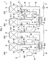
- the compressor 3, the four-way switching valve 4, the water heat exchanger 5, the expansion valve 6, and the air heat exchanger 7 are sequentially connected to each other via the refrigerant pipe 8.
- the air cooled chiller 1 can cope with either a cooling operation or a heating operation.
- the air cooled chiller 1 of the present embodiment shares one water heat exchanger 5 by the refrigerant circuits 2 having two systems. That is, in the refrigerant circuit 2, a first refrigerant circuit 21 and a second refrigerant circuit 22 share a first water heat exchanger 51, and a third refrigerant circuit 23 and a fourth refrigerant circuit 24 share a second water heat exchanger 52.
- the compressor 3 includes a motor (not shown) which is driven by an inverter. A rotating speed of the motor is adjusted by an output frequency of the inverter. By adjusting the rotating speed of the motor, a discharge amount of the refrigerant is adjusted.
- the water heat exchanger 5 includes a water piping 9, a water circulation pump 10, two refrigerant flow paths 53 and 54, and one water flow path 55.
- the water heat exchanger 5 performs heat exchange between water supplied to the water flow path 55 via the water piping 9 by the water circulation pump 10 and the refrigerant supplied to the refrigerant flow paths 53 and 54 through the refrigerant pipe 8 between the four-way switching valve 4 and the expansion valve 6.
- the water piping 9 includes a first water piping 91 through which the water is supplied to the water heat exchanger 5 and a second water piping 92 through which the water is discharged from the water heat exchanger 5.
- the expansion valve 6 is provided between the water heat exchanger 5 and the air heat exchanger 7.
- two expansion valves may be used such that the refrigerant expands in two steps.
- a capillary tube may be used instead of the expansion valve 6.
- the air heat exchanger 7 is provided between the four-way switching valve 4 and the expansion valve 6.
- the air heat exchanger 7 performs heat exchange between outside air and the refrigerant.
- Each air heat exchanger 7 and each machine section 20 are connected to each other by two refrigerant pipes 8.
- the refrigerant pipe 8 includes a first refrigerant pipe 8A which connects the air heat exchanger 7 and the expansion valve 6 to each other, a second refrigerant pipe 8B which connects the expansion valve 6 and the water heat exchanger 5, a third refrigerant pipe 8C which connects the water heat exchanger 5 and a third port 43 of the four-way switching valve 4, a fourth refrigerant pipe 8D which connects a second port 42 of the four-way switching valve 4 and the air heat exchanger 7, a fifth refrigerant pipe 8E which connects a discharge-side refrigerant pipe of the compressor 2 and a first port 41 of the four-way switching valve 4, and a sixth refrigerant pipe 8F which connects a suction portion of the compressor 2 and a fourth port 44 of the four-way switching valve 4.
- the air cooled chiller 1 of the present embodiment includes the refrigerant circuits 2 having four systems, and thus, eight air heat exchanger pipes 8A and 8D are provided.
- the first air heat exchanger 71 of the first refrigerant circuit 21 is connected to a first compressor 31 via the second air heat exchanger pipe 8D and the four-way switching valve 4.
- the second air heat exchanger 72 is connected to a second compressor 32 via the second air heat exchanger pipe 8D and the four-way switching valve 4.
- the third air heat exchanger 73 is connected to a third compressor 33 via the second air heat exchanger pipe 8D and the four-way switching valve 4.
- the fourth air heat exchanger 74 is connected to a fourth compressor 34 via the second air heat exchanger pipe 8D and the four-way switching valve 4.
- An accumulator may be provided between the suction portion of the compressor 3 and the four-way switching valve 4.
- the accumulator prevents the refrigerant which could not be gasified by an evaporator (the water heat exchanger 5 or the air heat exchanger 7) from being sucked into the compressor 3 in a liquid state.
- the refrigerant circuits 2 having four systems are unified so as to constitute the air cooled chiller 1 of the present embodiment.
- the air cooled chiller 1 includes a rectangular parallelepiped casing 12.
- the refrigerant circuits 2 having four systems of the air cooled chiller 1 are accommodated in the casing 12.
- the casing 12 has a substantially rectangular shape when viewed from above.
- a direction along a long side of an upper surface of the casing 12 is referred to as a longitudinal direction L1
- a direction along a short side of the upper surface of the casing 12 is referred to as a lateral direction L2.
- one surface facing the longitudinal direction L1 is defined as a front surface F
- a surface which is positioned on a side opposite to the front surface F and is parallel to the front surface F is defined as a rear surface R
- surfaces which connect the front surface F and the rear surface R to each other are defined as side surfaces S1 and S2.
- the side surfaces S1 and S2 are surfaces facing the lateral direction L2 and are surfaces which are wider than the front surface F and the rear surface R.
- a right surface when viewed from the front surface side is defined as a first side surface S1
- a left surface when viewed from the front surface side is defined as a second side surface S2.
- the shape of the casing 12 is not limited to the shape shown in Fig. 2 , and for example, may be a square shape, a circular shape, or a polygonal shape in a plan view.
- the air cooled chiller 1 includes a machine chamber 13 which is provided below the casing 12 and a heat exchange chamber 14 which is provided on a top plate 15 of the machine chamber 13. In other words, an internal space of the casing 12 is partitioned into the upper heat exchange chamber 14 and the lower machine chamber 13 by the top plate 15.
- the first water piping 91 which is a pipe through which water is supplied to the water heat exchanger 5 of the machine chamber 13 and a second water piping 92 which is a pipe through which the water is discharged from the water heat exchanger 5 of the machine chamber 13 are connected to the front surface F of the casing 12.
- a plurality of fans 16 are provided on the upper surface of the casing 12.
- the fans 16 are arranged at equal intervals in the longitudinal direction L1 of the casing 12.
- the air heat exchanger 7 is disposed in the heat exchange chamber 14.
- the machine section 20 (the refrigerant circuit 2 and the control device 19 except for the air heat exchanger 7) is disposed in the machine chamber 13.
- the top plate 15 is disposed between the air heat exchanger 7 and the machine section 20.
- the eight air heat exchanger pipes 8A and 8D extend over a portion above the top plate 15 and a portion below the top plate 15.
- the air heat exchanger 7 includes first headers 17A and second headers 17B which extend in a vertical direction, and a plurality of heat transfer tubes 18 which are connected to the first headers 17A and the second headers 17B and extend in a horizontal direction.
- the air heat exchanger pipes 8A extending from the machine section 20 are connected to the first headers, and the air heat exchanger pipes 8D extending from the machine section 20 are connected to the second headers 17B.
- One end of each heat transfer tube 18 is connected to the first header 17A and the other end of each heat transfer tube 18 is connected to the second header 17B.
- each air heat exchanger 7 is disposed in each accommodation space A.
- the four accommodation spaces A are partitioned by a first division surface D1 by which the heat exchange chamber 14 is divided into two portions in the longitudinal direction L1 and a second division surface D2 by which the heat exchange chamber 14 is divided into two portions in the lateral direction L2.
- the accommodation space A which is positioned on the rear surface R side and the first side surface S1 side is defined as a first accommodation space A1
- the accommodation space A which is positioned on the rear surface R side and the second side surface S2 side is defined as a second accommodation space A2
- the accommodation space A which is positioned on the front surface F side and the second side surface S2 side is defined as a third accommodation space A3
- the accommodation space A which is positioned on the front surface F side and the first side surface S1 side is defined as a fourth accommodation space A4.
- division surfaces D1 and D2 are virtual division surfaces, and for example, it is not necessary to physically partition the division surfaces by plates.
- four air heat exchangers 7 are sequentially provided in a circumferential direction of a reference axis C so as to surround the reference axis C extending in the vertical direction in the heat exchange chamber 14.
- the reference axis C of the present embodiment is disposed at a center of the casing 12 in a plan view.
- the reference axis C is an intersection line between the first division surface D1 and the second division surface D2.
- the reference axis C is not required to be disposed at the center of the casing 12 in a plan view.
- the first division surface D1 and the second division surface D2 do not need to equally divide an area of each accommodation space A.
- the first headers 17A and the second headers 17B are positioned in the vicinities of the side surfaces S1 and S2 in a plan view, and are disposed in the vicinity of a center in the longitudinal direction L1.
- the heat transfer tubes 18 extend from the first headers 17A and the second headers 17B toward the front surface F or the rear surface R and are formed to be bent inward in the lateral direction L2 in the vicinity of the front surface F or the rear surface R. In other words, the heat transfer tubes 18 extend along inner surfaces of the casing 12 from the first header 17A and the second header 17B.
- One pipe insertion hole 25 is formed on the top plate 15.
- the pipe insertion hole 25 is disposed at the center of the top plate 15 in the vicinity of an intersection between the top plate 15 and the reference axis C.
- the eight air heat exchanger pipes 8A and 8D are inserted into the pipe insertion hole 25.
- the pipe insertion hole 25 is not required to be formed at the center of the top plate 15, and the position of the pipe insertion hole 25 can be changed according to the dispositions of the compressors 3.
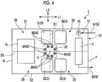
- the dispositions of the four compressors 3 correspond to the dispositions of the four air heat exchangers 7 in a plan view.
- the respective compressors 3 of the machine section 20 are disposed such that a relative positional relationship of the compressors 3 in a plan view in the machine chamber 13 corresponds to a relative positional relationship of the air heat exchangers 7 in a plan view in the heat exchange chamber 14.
- the relative positional relationship means a relative positional relationship of three or more objects.
- the relative positional relationship is a relative positional relationship of three or more objects when three or more objects are disposed on a predetermined plane, and includes an approximate shape of the shape formed by the three or more objects and an order in which the three or more objects are disposed.
- the four air heat exchangers 7 are disposed to form a rectangular shape.
- the four air heat exchangers 7 are sequentially disposed in the accommodation spaces A in the counterclockwise direction from the first air heat exchanger 71 to the fourth air heat exchanger 74 with the first accommodation space A1 as a starting point.
- the four compressors 3 are disposed such that the four compressors 3 form a rectangular shape.
- the four compressors 3 are disposed in the counterclockwise direction from the first compressor 31 to the fourth compressor 34.
- the position of the first compressor 31 corresponds to the position of the first air heat exchanger 71
- the position of the second compressor 32 corresponds to the position of the second air heat exchanger 72
- the position of the third compressor 33 corresponds to the position of the third air heat exchanger 73
- the position of the fourth compressor 34 corresponds to the position of the fourth air heat exchanger 74.
- the first compressor 31 is disposed at a position closest to the first air heat exchanger 71.
- the second compressor 32 is disposed at a position closest to the second air heat exchanger 72
- the third compressor 33 is disposed at a position closest to the third air heat exchanger 73
- the fourth compressor 34 is disposed at a position closest to the fourth air heat exchanger 74.
- the control device 19 is disposed between the rear surface R of the machine chamber 13 and four compressors 3.
- the water heat exchanger 5 is disposed between the front surface F and the four compressors 3.
- the positions of the air heat exchangers 7 in a plan view correspond to the positions of the compression units 3 in a plan view, and thus, it is possible to prevent dispositions of the refrigerant pipes 8 (air heat exchanger pipes 8A and 8D) positioned between the air heat exchangers 7 and the compressors 3 from being complicated. Accordingly, it is possible to improve maintenance of the air cooled chiller 1. In addition, the dispositions of the refrigerant pipes 8 are not complicated, and thus, it is possible to improve assembling properties.
- the pipe insertion hole 25 is formed on the top plate 15, and thus, the plurality of refrigerant pipes 8 can be collected in the pipe insertion hole 25. Accordingly, it is possible to further improve the maintenance of the air cooled chiller 1.
- the pipe insertion hole 25 is formed at the center of the top plate 15, and thus, lengths of the plurality of refrigerant pipes 8 can be reduced, and it is possible to decrease a manufacturing cost of the air cooled chiller 1.
- a plurality of control devices 19B of the air cooled chiller 1B of the present embodiment are provided to correspond to the respective refrigerant circuits 2.
- the control devices 19B control the refrigerant circuits 2 respectively corresponding to the control devices 19B.
- the respective control devices 19B are disposed in the vicinities of the compressors 3 such that a relative positional relationship of the respective control devices 19B in the machine chamber 13 in a plan view correspond to a relative positional relationship of the air heat exchangers 7 in a plan view in the heat exchange chamber 14 .
- the pipe insertion hole 25 of the present embodiment is not disposed at the center of the top plate 15, and is deviated in the longitudinal direction L1 according to the positions of the compressors 3.
- the compressors 3 of the present embodiment are disposed to be close to the rear surface R
- the pipe insertion hole 25 is also disposed to be close to the rear surface R according to the dispositions of the compressors 3.
- the pipe insertion hole 25 is positioned at the positions corresponding to the compressors 3, and thus, a length of the refrigerant pipe 8 can be optimized.
- the present invention is not limited to this and can be applied to an air cooled chiller having refrigerant circuits including three or more systems.
- the configuration in which the water heat exchangers are shared by the refrigerant circuits having two systems is not limited to this, and the water heat exchanger may be provided in each refrigerant circuit. In addition, one water heat exchanger may be shared by the refrigerant circuits having four systems.
- a plurality of pipe insertion holes 25 may be provided according to the dispositions of the compressors 3.
- the structure of the air heat exchanger is not limited to the above-described structure.
- a heat transfer plate (fin) may be attached to the heat transfer tube, and a plate-type heat exchanger may be adopted.
Landscapes
- Engineering & Computer Science (AREA)
- Mechanical Engineering (AREA)
- General Engineering & Computer Science (AREA)
- Chemical & Material Sciences (AREA)
- Combustion & Propulsion (AREA)
- Physics & Mathematics (AREA)
- Thermal Sciences (AREA)
- Other Air-Conditioning Systems (AREA)
- Life Sciences & Earth Sciences (AREA)
- Sustainable Development (AREA)
- Air Filters, Heat-Exchange Apparatuses, And Housings Of Air-Conditioning Units (AREA)
Applications Claiming Priority (2)
| Application Number | Priority Date | Filing Date | Title |
|---|---|---|---|
| JP2016202648A JP2018063097A (ja) | 2016-10-14 | 2016-10-14 | 空冷チラー |
| PCT/JP2017/036811 WO2018070422A1 (ja) | 2016-10-14 | 2017-10-11 | 空冷チラー |
Publications (2)
| Publication Number | Publication Date |
|---|---|
| EP3441685A1 true EP3441685A1 (de) | 2019-02-13 |
| EP3441685A4 EP3441685A4 (de) | 2019-05-08 |
Family
ID=61906295
Family Applications (1)
| Application Number | Title | Priority Date | Filing Date |
|---|---|---|---|
| EP17860146.4A Withdrawn EP3441685A4 (de) | 2016-10-14 | 2017-10-11 | Luftkühler |
Country Status (5)
| Country | Link |
|---|---|
| EP (1) | EP3441685A4 (de) |
| JP (1) | JP2018063097A (de) |
| KR (1) | KR20180132793A (de) |
| CN (1) | CN109073245A (de) |
| WO (1) | WO2018070422A1 (de) |
Cited By (2)
| Publication number | Priority date | Publication date | Assignee | Title |
|---|---|---|---|---|
| RU193484U1 (ru) * | 2019-08-29 | 2019-10-31 | Антон Юрьевич Дымов | Двухконтурный чиллер с двумя компрессорами в каждом контуре |
| US20220221228A1 (en) * | 2019-08-07 | 2022-07-14 | Mitsubishi Electric Corporation | Chilling unit |
Families Citing this family (3)
| Publication number | Priority date | Publication date | Assignee | Title |
|---|---|---|---|---|
| JP6269717B2 (ja) * | 2016-04-21 | 2018-01-31 | ダイキン工業株式会社 | 熱源ユニット |
| CN115235150B (zh) * | 2022-06-23 | 2023-08-25 | 合肥丰蓝电器有限公司 | 一种自动切换的压缩机控制系统 |
| WO2025158781A1 (ja) * | 2024-01-23 | 2025-07-31 | 日本キヤリア株式会社 | 熱源機 |
Family Cites Families (10)
| Publication number | Priority date | Publication date | Assignee | Title |
|---|---|---|---|---|
| CN101240915B (zh) * | 2008-03-04 | 2012-10-03 | 王全龄 | 立管换热器式空调器 |
| WO2010095470A1 (ja) * | 2009-02-23 | 2010-08-26 | ダイキン工業株式会社 | 熱交換器、室外機及び冷凍装置 |
| KR20100121961A (ko) * | 2009-05-11 | 2010-11-19 | 엘지전자 주식회사 | 공기조화기 |
| JP2010266126A (ja) * | 2009-05-14 | 2010-11-25 | Hitachi Appliances Inc | 熱交換ユニット |
| CN201539921U (zh) * | 2009-08-28 | 2010-08-04 | 海信科龙电器股份有限公司 | 一种空调室外机 |
| CN102753895B (zh) * | 2010-02-15 | 2015-07-15 | 东芝开利株式会社 | 致冷单元 |
| JP5817775B2 (ja) * | 2013-04-12 | 2015-11-18 | ダイキン工業株式会社 | チラー装置 |
| CN105473951A (zh) * | 2013-07-01 | 2016-04-06 | 特灵空调系统(中国)有限公司 | 空调室外机 |
| CN204535202U (zh) * | 2014-12-31 | 2015-08-05 | 济南神华制冷设备有限公司 | 双效无垢节能蒸发式冷凝器 |
| CN105485958A (zh) * | 2016-01-06 | 2016-04-13 | 王言明 | 免除霜风冷、水冷一体机空气源热泵 |
-
2016
- 2016-10-14 JP JP2016202648A patent/JP2018063097A/ja active Pending
-
2017
- 2017-10-11 CN CN201780026521.6A patent/CN109073245A/zh active Pending
- 2017-10-11 WO PCT/JP2017/036811 patent/WO2018070422A1/ja not_active Ceased
- 2017-10-11 EP EP17860146.4A patent/EP3441685A4/de not_active Withdrawn
- 2017-10-11 KR KR1020187031787A patent/KR20180132793A/ko not_active Ceased
Cited By (3)
| Publication number | Priority date | Publication date | Assignee | Title |
|---|---|---|---|---|
| US20220221228A1 (en) * | 2019-08-07 | 2022-07-14 | Mitsubishi Electric Corporation | Chilling unit |
| US12228346B2 (en) * | 2019-08-07 | 2025-02-18 | Mitsubishi Electric Corporation | Chilling unit |
| RU193484U1 (ru) * | 2019-08-29 | 2019-10-31 | Антон Юрьевич Дымов | Двухконтурный чиллер с двумя компрессорами в каждом контуре |
Also Published As
| Publication number | Publication date |
|---|---|
| CN109073245A (zh) | 2018-12-21 |
| KR20180132793A (ko) | 2018-12-12 |
| JP2018063097A (ja) | 2018-04-19 |
| WO2018070422A1 (ja) | 2018-04-19 |
| EP3441685A4 (de) | 2019-05-08 |
Similar Documents
| Publication | Publication Date | Title |
|---|---|---|
| US10670344B2 (en) | Heat exchanger, air-conditioning apparatus, refrigeration cycle apparatus and method for manufacturing heat exchanger | |
| EP3441685A1 (de) | Luftkühler | |
| AU2018242788B2 (en) | Heat exchanger | |
| US10465924B2 (en) | Heat exchanger | |
| US10041710B2 (en) | Heat exchanger and air conditioner | |
| EP3473963A1 (de) | Wärmetauscher und klimaanlage | |
| US11274838B2 (en) | Air-conditioner outdoor heat exchanger and air-conditioner including the same | |
| US10150350B2 (en) | Vehicle heat exchanger | |
| WO2020039513A1 (ja) | 熱交換器及び空気調和装置 | |
| WO2016076259A1 (ja) | 熱交換器 | |
| US11994352B2 (en) | Heat exchanger | |
| JP2012202636A (ja) | 空気調和機の室外機 | |
| JP7357785B2 (ja) | 熱交換器、熱交換器を備えた室外機、および、室外機を備えた空気調和装置 | |
| KR20160147342A (ko) | 차량용 에어컨 시스템 | |
| JP2016125774A (ja) | 冷凍サイクル装置 | |
| JP7642170B1 (ja) | 熱交換器、熱交換器を備えた室外機、および、室外機を備えた空気調和装置 | |
| JP7142806B1 (ja) | 分配器、熱交換器およびヒートポンプ装置 | |
| JP7836969B2 (ja) | 熱交換器 | |
| JP7496832B2 (ja) | 熱交換器、熱交換器ユニット、冷凍サイクル装置、及び熱交換部材の製造方法 | |
| WO2025182083A1 (ja) | 熱交換器、熱交換器を備えた空気調和装置の室外機、および、空気調和装置の室外機を備えた空気調和装置 | |
| US20220373264A1 (en) | Heat exchanger, heat exchanger unit, and refrigeration cycle apparatus | |
| WO2024224513A1 (ja) | 熱交換器及び空気調和装置 | |
| WO2023195040A1 (ja) | 熱交換器、および空気調和機の室外機 | |
| WO2025169459A1 (ja) | 熱交換器及び空気調和装置 | |
| KR20140087920A (ko) | 듀얼 냉동시스템의 응축기 구조 |
Legal Events
| Date | Code | Title | Description |
|---|---|---|---|
| STAA | Information on the status of an ep patent application or granted ep patent |
Free format text: STATUS: THE INTERNATIONAL PUBLICATION HAS BEEN MADE |
|
| PUAI | Public reference made under article 153(3) epc to a published international application that has entered the european phase |
Free format text: ORIGINAL CODE: 0009012 |
|
| STAA | Information on the status of an ep patent application or granted ep patent |
Free format text: STATUS: REQUEST FOR EXAMINATION WAS MADE |
|
| 17P | Request for examination filed |
Effective date: 20181106 |
|
| AK | Designated contracting states |
Kind code of ref document: A1 Designated state(s): AL AT BE BG CH CY CZ DE DK EE ES FI FR GB GR HR HU IE IS IT LI LT LU LV MC MK MT NL NO PL PT RO RS SE SI SK SM TR |
|
| AX | Request for extension of the european patent |
Extension state: BA ME |
|
| A4 | Supplementary search report drawn up and despatched |
Effective date: 20190410 |
|
| RIC1 | Information provided on ipc code assigned before grant |
Ipc: F24F 11/30 20180101ALI20190404BHEP Ipc: F24F 1/26 20110101ALI20190404BHEP Ipc: F24F 1/24 20110101ALI20190404BHEP Ipc: F24F 1/10 20110101ALI20190404BHEP Ipc: F24F 1/46 20110101ALI20190404BHEP Ipc: F24F 5/00 20060101ALI20190404BHEP Ipc: F25B 1/00 20060101ALI20190404BHEP Ipc: F24F 1/30 20110101ALI20190404BHEP Ipc: F24F 13/30 20060101ALI20190404BHEP Ipc: F24F 1/16 20110101AFI20190404BHEP |
|
| DAV | Request for validation of the european patent (deleted) | ||
| DAX | Request for extension of the european patent (deleted) | ||
| STAA | Information on the status of an ep patent application or granted ep patent |
Free format text: STATUS: THE APPLICATION IS DEEMED TO BE WITHDRAWN |
|
| 18D | Application deemed to be withdrawn |
Effective date: 20191112 |