EP3441745B1 - Dispositif de surveillance d'environnement corrosif - Google Patents
Dispositif de surveillance d'environnement corrosif Download PDFInfo
- Publication number
- EP3441745B1 EP3441745B1 EP17778886.6A EP17778886A EP3441745B1 EP 3441745 B1 EP3441745 B1 EP 3441745B1 EP 17778886 A EP17778886 A EP 17778886A EP 3441745 B1 EP3441745 B1 EP 3441745B1
- Authority
- EP
- European Patent Office
- Prior art keywords
- thin film
- metal thin
- environment monitoring
- corrosive environment
- monitoring device
- Prior art date
- Legal status (The legal status is an assumption and is not a legal conclusion. Google has not performed a legal analysis and makes no representation as to the accuracy of the status listed.)
- Active
Links
Images





Classifications
-
- G—PHYSICS
- G01—MEASURING; TESTING
- G01N—INVESTIGATING OR ANALYSING MATERIALS BY DETERMINING THEIR CHEMICAL OR PHYSICAL PROPERTIES
- G01N17/00—Investigating resistance of materials to the weather, to corrosion, or to light
- G01N17/04—Corrosion probes
Definitions
- the present invention relates to a corrosive environment monitoring device for an indoor environment, mainly an environment where an electrical/electronic device is installed, which measures the degree of corrosion due to a corrosive gas present in the environment.
- An electrical/electronic device is required to provide long-term reliability in order to enable an intended apparatus to operate stably.
- many electrical/electronic components which adopt a high-density packaging structure and include a micro-wiring structure or thin film plating structure are mounted.
- minor corrosion damage may change the electric characteristics or magnetic characteristics and cause a failure or malfunctioning, so suppression of corrosion damage is an issue to be tackled from the viewpoint of the reliability of electrical/electronic devices.
- the device which diagnoses the corrosiveness of the environment is also expected to be compact and lightweight for space saving.
- ASHRAE American Society of Heating Refrigerating and Air Conditioning Engineering, Inc.
- TC9.9 2011 Gaseous and Particulate Contamination Guidelines for Data Centers.
- the degree of corrosion of metal exposed for one month is quantified by electrochemical measurement.
- PTL 1 and PTL 2 describe "an atmosphere investigation method as a method for measuring the kind and concentration of a corrosive gas present in an environmental atmosphere, characterized in that regarding five kinds of metal pieces of copper, silver, aluminum, iron, and 52 alloy, a calibration curve of an X ray microanalyzer showing correlative relationship between corrosive gas concentration and X-ray intensity of a corrosion product generated by exposure for a prescribed period is determined in advance and the five kinds of metal pieces are left in an investigated environmental atmosphere for a prescribed period, the kind of corrosive gas is estimated from a corrosion condition, then the X-ray intensity of a corrosive gas component of the corrosion product is calculated by the X-ray microanalyzer, and the gas concentration is calculated by comparison with the calibration curve".
- PTL 3 describes "an environment evaluation method characterized in that thin films of two or more different materials including a metal or alloy thereof or compound thereof are formed on one insulating substrate sequentially, the thin films have different physical and/or chemical properties and constitute detecting elements for detecting a plurality of gas components in an environment by using differences in the physical and/or chemical properties of the thin films, and the environment is evaluated by detecting change in the physical and/or chemical properties of the materials of the elements, and an environment evaluation device which uses the method".
- PTL 4 describes "a corrosive environment monitoring device characterized by having a first and a second corrosive environment monitoring device including a passage structure with one opening, a transparent substrate formed as one wall face of the passage structure parallel to a diffusion direction of a corrosive substance from the opening, and a thin metal film formed on the transparent substrate, in which the first and the second corrosive environment monitoring device can measure the shape and size of an area whose color tone has changed due to a corrosion product of the metal thin film left in a measured environment for a prescribed period, through the transparent substrate, and the metal thin film of the first corrosive environment monitoring device is made of a prescribed material and the metal thin film of the second corrosive environment monitoring device is made of a material different from the material of the metal thin film of the first corrosive environment monitoring device.
- the optical reflectance and optical transmittance of the thin film element and change of the electric resistance element are detected and converted into electric signals and thus a power supply to drive the electric circuit is required.
- a problem that due to the customer's circumstances it may be impossible to prepare a power supply and thus it may be difficult to use an environment measuring device.
- the corrosive environment monitoring device in PTL 4 is a corrosive environment monitoring device which includes a passage structure with one opening, a transparent substrate formed as one wall face of the passage structure parallel to the diffusion direction of a corrosive substance from the opening, and a metal thin film formed on the transparent substrate, and when the metal plate is exposed, can calculate the thickness of corrosion from the length of the discolored area of the metal thin film.
- a problem is that in the case of exposure for one month as specified in the ASHRA guidelines, the discolored area of the metal thin film is small and short and thus it is difficult to evaluate the degree of corrosion of the metal in accordance with the ASHRA guidelines (allowable silver corrosion thickness not more than 20 nm, copper corrosion thickness not more than 30 nm).
- the present invention has an object to provide a corrosive environment monitoring device which can measure the degree of corrosion of metal in a tiny space inside an electronic device housing as an object of diagnosis on the spot for a short to long term without the need for a special analyzer and without the need for a power source such as a commercial power supply or battery.
- the present invention provides a corrosive environment monitoring device with the features of claim 1.
- the present invention it is possible to measure the degree of corrosion of metal in a tiny space inside an electronic device housing as an object of diagnosis on the spot for a short to long term without the need for a special analyzer and without the need for a power source such as a commercial power supply or battery.
- corrosiveness in a relatively clean environment after a short term or one month of exposure can be diagnosed in accordance with the ASHRA guidelines and also corrosiveness in a relatively polluted environment after a long term or one year of exposure can be diagnosed in accordance with the ISO11844-1 standards.
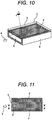
- Figure 10 is a perspective view of the conventional corrosive environment monitoring device
- Figure 11 is a top view of the conventional corrosive environment monitoring device
- Figure 12 is a sectional view taken along the line B-B of Figure 11 .
- a passage structure 4 with one end closed and the other end as an opening 5 is formed in a box-shaped center area.
- the top face is formed as a metal thin film 2 and the metal thin film 2 is covered by a transparent substrate 3. Consequently, the degree of corrosion of the metal thin film 2 can be visually checked from above the corrosive environment monitoring device 1.
- the metal thin film 2 constitutes a sensor part and is attached to one wall face in the passage structure 4 with the opening 5 (top face in the case of Figure 10 ).
- the metal thin film 2 is attached so that its film surface is on the passage structure 4 side and the transparent substrate 3 is on the surrounding atmosphere side, namely the metal thin film 2 can be observed through the transparent substrate 3 from the surrounding atmosphere side (from above in Figure 10 ).
- a metal which is different in color tone between the metal and a corrosion product such as aluminum, iron, and zinc, may be used in addition to copper and silver which are used for corrosive environment monitoring of the installation environment of an electrical/electronic device.
- a corrosive substance 6 present in the environment enters the passage structure 4 through the opening 5 and corrodes the metal thin film 2.
- the passage structure 4 has a role to control the speed at which the metal thin film 2 as the sensor part is corroded by the corrosive substance 6.
- the passage structure 4 has one opening 5 (on the left side of the passage structure shown in Figures 11 and 12 ) and no opening is provided on the right side of the passage structure which is isolated from the surrounding environment.
- corrosive substances include a corrosive gas, flying sea salt, and dust, but a corrosive gas is hereinafter described as representative of the corrosive substances.
- the progress of corrosion stops in an area where the corrosion thickness is equal to the thickness of the metal thin film 2 (area where the metal thin film 2 has corroded up to the boundary face with the transparent substrate 3).
- this area of the metal thin film 2 is observed from the transparent substrate 3 side, it can be confirmed that the metal color tone of the metal thin film 2 has changed to the color tone of a corrosion product.
- the corrosion condition of the metal thin film 2 after exposure of the corrosive environment monitoring device 1 is shown in the top view of Figure 13 and the sectional view of Figure 14 , taken along the line B-B. According to Figure 13 , corrosion does not progress further in the area where due to the progress of corrosion of the metal thin film 2, the corrosion thickness becomes equal to the thickness of the thin film (area where the metal thin film has corroded up to the boundary face with the substrate).
- the corrosive gas 6 present in the environment continues to diffuse from left or near the opening 5 and further corrodes the metal thin film on the right.
- corrosiveness of an environment is diagnosed according to the thickness of a corrosion product of metal exposed for one month.
- the thickness of the corrosion product of the exposed metal can be calculated by the prior art from the length of the metal thin film area 7 corroded entirely in the film thickness direction in the corrosive environment monitoring device.
- the extension speed of the length of the metal thin film area 7 corroded entirely in the film thickness direction depends on the thickness of the metal thin film and the height of the opening. The extension speed is higher when the metal thin film is thinner and the height of the opening is larger.
- Figure 15 shows an example of the relation between the length of the area 7 of the metal thin film 2 which is corroded entirely in the film thickness direction and the thickness of the corrosion product of the exposed metal plate in the corrosive environment monitoring device 1.
- the horizontal axis represents the length of the discolored area 7 and the vertical axis represents the thickness of the corrosion product of the exposed metal plate.
- the figure shows characteristics when the silver thin film thickness is 20 nm, the passage height is 2 mm, the passage width is 5 mm, and the passage length is 20 mm.
- corrosiveness of an environment is diagnosed according to the thickness of a corrosion product of metal exposed for one month and in the ISO11844-1 standards, corrosiveness of an environment is diagnosed according to the thickness of a corrosion product of metal exposed for one year.
- Figures 1 to 7 show an example of the structure and the effect of the corrosive environment monitoring device according to Example 1 of the present invention.
- Figure 1 is a perspective view which shows the general structure of the corrosive environment monitoring device according to Example 1
- Figure 2 is a top view thereof
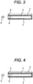
- Figure 3 is a sectional view taken along the line A-A of Figure 2
- Figure 4 is a sectional view taken along the line B-B of Figure 2 .
- Figures 5, 6, and 7 are a top view showing the corrosion condition of the metal thin film after exposure of the corrosive environment monitoring device in Example 1, a sectional view of the corrosive environment monitoring device, taken along the line A-A of Figure 5 , and a sectional view of the corrosive environment monitoring device, taken along the line B-B of Figure 5 , respectively.
- the corrosive environment monitoring device 1 in Example 1 is provided with a plurality of sets of corrosive environment monitoring parts (two sets in Figure 1 ).
- the corrosion detection conditions in the corrosive environment monitoring parts are differentiated.
- the metal thin film 2 as a sensor part includes a first metal thin film 2 which has the same condition as in Figure 10 (the top face of the passage structure 4 is entirely covered by a metal thin film) and a second metal thin film 2' which has a different condition (the metal thin film lies on part of the top face of the passage structure 4 in the depth direction).
- the other conditions (the structure of the passage structure 4, corrosive gas 6, etc.) are the same.
- the corrosive environment monitoring device 1 has sensor parts as the metal thin films 2 and 2' attached onto the transparent substrate 3.
- the metal thin film 2 has the same width as the passage structure 4 and the metal thin film 2' has a smaller width than the passage structure 4.
- Figure 8 shows an example of the relation between the length of the area 7 of the metal thin film 2 which is corroded entirely in the film thickness direction and the thickness of the corrosion product of the exposed metal plate in the corrosive environment monitoring device 1, though the figure compares the wider sensor (metal thin film 2) and the narrower sensor (metal thin film 2') to show the difference in characteristics.
- the example in Figure 8 shows the measurement result in the case that the narrower metal thin film 2' has a silver thin film width of 1 mm, a silver thin film thickness of 20 nm, a passage height of 2 mm, a passage width of 20 mm, and a passage length of 20 mm, and the wider metal thin film 2 has a silver thin film width of 5 mm, a silver thin film thickness of 20 nm, a passage height of 2 mm, a passage width of 5 mm, and a passage length of 20 mm.
- the narrower metal thin film 2' can be used to calculate the thickness of the corrosion product of the metal exposed for one month in accordance with the ASHRAE guidelines and the wider metal thin film 2 can be used to calculate the thickness of the corrosion product of the metal exposed for one year in accordance with the ISO11844-1 standards.
- the thickness of the corrosion product can be calculated by two different methods to take the average. Furthermore, by calculating the ratio of the length of the discolored area of the narrower metal thin film to the length of the discolored area of the wider metal thin film, the thickness of the corrosion product can be calculated from the ratio. Furthermore, in the corrosive environment monitoring device 1 according to Example 1, the thickness of the corrosion product can be estimated accurately by calculating the thickness of the corrosion product by three different methods and taking the average.
- Figure 9 shows an example of the relation between the ratio of the length of the discolored area of the narrower metal thin film to the length of the discolored area of the wider metal thin film as calculated from Figure 8 and corrosion thickness.
- the ratio of the length of the discolored area and corrosion thickness have a good linear relation in the range where the absolute amount of corrosion thickness is small. This method is a desirable method for estimating the thickness of the corrosion product accurately.
- Figures 16 and 17 show an example of the structure of the corrosive environment monitoring device according to Example 2, an embodiment of the present invention.
- Figure 16 is a perspective view and
- Figure 17 is a top view.
- sensor parts as two sets of metal thin films 2 attached onto the transparent substrate 3 are disposed. Both the metal thin films 2 have the same width as the passage structure 4. However, the openings 5 and 5' of the passage structure 4 are different in height.
- the corrosion condition of the metal thin film after exposure of the corrosive environment monitoring device 1 is shown in the top view of Figure 18 .
- the corrosive gas 6 diffuses more inward in the passage of the opening 5' than in the passage of the opening 5 because the opening 5' is larger. Therefore, even though the metal thin films 2 are the same in thickness, the measurement result is that the length of the discolored area of the opening 5' (distance from the left end to point A in Figure 18 ) is larger than the length of the discolored area of the opening 5 (distance from the left end to point B in Figure 18 ).
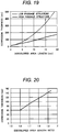
- Figure 19 shows an example of the relation between the length of the discolored area of the metal thin film and corrosion thickness. This is the result of measurement in which the high passage structure has a silver thin film thickness of 20 nm, a passage height of 10 mm, a passage width of 5 mm, and a passage length of 20 mm and the low passage structure has a silver thin film thickness of 20 nm, a passage height of 2 mm, a passage width of 5 mm and a passage length of 20 mm.
- the high opening 5' can be used to calculate the thickness of the corrosion product of the metal exposed for one month in accordance with the ASHRAE guidelines and the low opening 5 can be used to calculate the thickness of the corrosion product of the metal exposed for one year in accordance with the ISO11844-1 standards.
- the thickness of the corrosion product can be calculated by two different methods to take the average. Furthermore, since two types of metal thin films are used, the ratio of the length of the discolored area of the high opening (narrower opening) to the length of the discolored area of the low opening (wider opening) can be calculated to determine the thickness of the corrosion product from this ratio. In addition, in the corrosive environment monitoring device 1 in Example 2, the thickness of the corrosion product can be estimated accurately by calculating the corrosion product thicknesses by three different methods and taking the average.
- the reason for this is the same as in the abovementioned method with the narrower metal thin film and wider metal thin film.
- Figure 19 it has been found that the relation between the length of the discolored area of the metal thin film and corrosion thickness is linear when the opening is higher and conversely the relation is nonlinear when the opening is lower.
- the thickness of the corrosion product can be calculated from the ratio of the length of the discolored area of the high opening to the length of the discolored area of the low opening.
- Figure 20 shows an example of the relation between the ratio of the length of the discolored area of the metal thin film of the high opening to the length of the discolored area of the metal thin film of the low opening as calculated from Figure 19 and corrosion thickness. According to this, the ratio of the length of the discolored area and corrosion thickness have a good linear relation in the range where the absolute amount of corrosion thickness is small. This method is a desirable method for estimating the thickness of the corrosion product accurately.
- Figure 21 shows an example of the structure of the corrosive environment monitoring device according to Example 3, another embodiment of the present invention.
- Figure 21 shows a method which combines the relation between the wider and narrower metal thin films in Example 1 and the relation between the high and low openings in Example 2.
- the passage structure with openings different in height in Example 2 and metal thin films with different widths are combined to constitute a device which includes a sensing part with the narrower metal thin film attached to the high opening passage and a sensing part with the wider metal thin film attached to the low opening passage.
- the good linear relation between the ratio of the length of the discolored area and corrosion thickness can be maintained and further the sensing part with the wider metal thin film attached to the low opening passage can be used to calculate the thickness of the corrosion product of the metal exposed for one month in accordance with the ASHRAE guidelines and the sensing part with the wider metal thin film attached to the low opening passage can be used to calculate the thickness of the corrosion product of the metal exposed for one year in accordance with the ISO11844-1 standards.
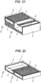
- Figure 22 shows an example of the structure of the corrosive environment monitoring device according to Example 4, not within the scope of the present invention.
- Figure 22 shows a method which combines the relation between the wider and narrower metal thin films in Example 1 and the relation between the high and low openings in Example 2.
- the corrosive environment monitoring device 1 includes sensor parts constituted by metal thin films 2 and 2' attached onto the transparent substrate 3.
- the metal thin film 2 has the same width as the passage structure 4 and the metal thin film 2' has a smaller width than the passage structure 4.
- the metal thin film 2' is attached in a manner to contact the side wall face of the opening.
- attachment in a manner to contact the side wall face can bring about the same effect as a structure having a substantially twice larger width and can contribute to space saving of the corrosive environment monitoring device.
Landscapes
- Life Sciences & Earth Sciences (AREA)
- Biodiversity & Conservation Biology (AREA)
- Ecology (AREA)
- Environmental & Geological Engineering (AREA)
- Environmental Sciences (AREA)
- Physics & Mathematics (AREA)
- Health & Medical Sciences (AREA)
- Chemical & Material Sciences (AREA)
- Analytical Chemistry (AREA)
- Biochemistry (AREA)
- General Health & Medical Sciences (AREA)
- General Physics & Mathematics (AREA)
- Immunology (AREA)
- Pathology (AREA)
- Testing Resistance To Weather, Investigating Materials By Mechanical Methods (AREA)
Claims (5)
- Dispositif de surveillance d'environnement corrosif, comprenant une partie capteur dans laquelle est prévue une structure de passage en forme de boîte (4) avec une extrémité fermée, et
dans lequel la structure de passage a une pluralité d'ouvertures à une autre extrémité, et chacune des ouvertures a un film mince en métal (2) situé sur une face d'une face supérieure, inférieure ou latérale de l'ouverture particulière et le film mince en métal (2) est couvert par un substrat transparent (3),
dans lequel le dispositif de surveillance d'environnement corrosif (1) inclut une pluralité de parties de surveillance d'environnement corrosif situées de manière adjacente à la pluralité d'ouvertures,
caractérisé en ce que les ouvertures sont différentes en taille de sorte que des conditions de détection de corrosion du film mince en métal (2) dans la pluralité de parties de surveillance d'environnement corrosif sont différenciées. - Dispositif de surveillance d'environnement corrosif (1) selon la revendication 1, dans lequel, afin de différencier les conditions de détection de corrosion du film mince en métal (2), une largeur du film mince en métal (2) dans une direction en profondeur de la structure de passage (4) est différenciée.
- Dispositif de surveillance d'environnement corrosif (1) selon la revendication 2, dans lequel, pour ce qui concerne les largeurs des films minces en métal dans les parties de surveillance d'environnement corrosif, un rapport de film mince en métal (2) de celles-ci n'est pas supérieur à un cinquième.
- Dispositif de surveillance d'environnement corrosif (1) selon la revendication 1, dans lequel, pour ce qui concerne les aires d'ouverture de la structure de passage (4) dans les parties de surveillance d'environnement corrosif, un rapport d'aire d'ouverture de celles-ci n'est pas supérieur à un cinquième.
- Dispositif de surveillance d'environnement corrosif (1) selon l'une quelconque des revendications 1 à 4, dans lequel un matériau du film mince en métal (2) inclut au moins un élément parmi : cuivre, argent, placage d'or, fer, alliage fer-nickel, aluminium ou zinc.
Applications Claiming Priority (2)
| Application Number | Priority Date | Filing Date | Title |
|---|---|---|---|
| JP2016077716 | 2016-04-08 | ||
| PCT/JP2017/006835 WO2017175507A1 (fr) | 2016-04-08 | 2017-02-23 | Dispositif de surveillance d'environnement corrosif |
Publications (3)
| Publication Number | Publication Date |
|---|---|
| EP3441745A1 EP3441745A1 (fr) | 2019-02-13 |
| EP3441745A4 EP3441745A4 (fr) | 2020-01-01 |
| EP3441745B1 true EP3441745B1 (fr) | 2021-04-07 |
Family
ID=60001001
Family Applications (1)
| Application Number | Title | Priority Date | Filing Date |
|---|---|---|---|
| EP17778886.6A Active EP3441745B1 (fr) | 2016-04-08 | 2017-02-23 | Dispositif de surveillance d'environnement corrosif |
Country Status (4)
| Country | Link |
|---|---|
| EP (1) | EP3441745B1 (fr) |
| JP (1) | JP6609038B2 (fr) |
| CN (1) | CN109073533B (fr) |
| WO (1) | WO2017175507A1 (fr) |
Families Citing this family (4)
| Publication number | Priority date | Publication date | Assignee | Title |
|---|---|---|---|---|
| US10330586B2 (en) * | 2016-07-20 | 2019-06-25 | Honeywell International Inc. | Corrosion monitor |
| JP7033034B2 (ja) * | 2018-08-23 | 2022-03-09 | 株式会社日立製作所 | 腐食環境モニタリング方法および腐食環境モニタリングシステム |
| JP7401387B2 (ja) * | 2020-04-22 | 2023-12-19 | 株式会社日立製作所 | 腐食環境モニタリング装置 |
| CN114236105B (zh) * | 2021-11-30 | 2023-11-28 | 浙江省二建建设集团有限公司 | 一种垃圾池壁混凝土腐蚀的监测装置及方法 |
Family Cites Families (10)
| Publication number | Priority date | Publication date | Assignee | Title |
|---|---|---|---|---|
| JP2008281499A (ja) * | 2007-05-14 | 2008-11-20 | Ntn Corp | 腐食環境センサおよびセンサシステム |
| JP4929062B2 (ja) * | 2007-06-05 | 2012-05-09 | 三菱重工業株式会社 | 試験体及び試験体の製造方法 |
| US8390306B2 (en) * | 2010-08-11 | 2013-03-05 | International Business Machines Corporation | Corrosion sensors |
| JP5828900B2 (ja) * | 2011-09-20 | 2015-12-09 | 株式会社日立製作所 | 腐食環境モニタ装置およびその方法 |
| JP5798955B2 (ja) * | 2012-03-13 | 2015-10-21 | 株式会社日立製作所 | 腐食環境モニタリング装置 |
| US9109989B2 (en) * | 2012-04-04 | 2015-08-18 | International Business Machines Corporation | Corrosion detector apparatus for universal assessment of pollution in data centers |
| CN202533402U (zh) * | 2012-05-04 | 2012-11-14 | 山东电力研究院 | 大气环境污染物腐蚀监测传感器 |
| CN102645457A (zh) * | 2012-05-04 | 2012-08-22 | 山东电力研究院 | 大气环境污染物腐蚀监测传感器 |
| JP6362920B2 (ja) * | 2014-05-16 | 2018-07-25 | 株式会社日立製作所 | 腐食環境モニタリング装置及び方法 |
| CN106226226B (zh) * | 2016-07-11 | 2019-04-02 | 国网山东省电力公司电力科学研究院 | 一种大气环境腐蚀性检测传感器及评价方法 |
-
2017
- 2017-02-23 EP EP17778886.6A patent/EP3441745B1/fr active Active
- 2017-02-23 JP JP2018510264A patent/JP6609038B2/ja active Active
- 2017-02-23 CN CN201780022360.3A patent/CN109073533B/zh active Active
- 2017-02-23 WO PCT/JP2017/006835 patent/WO2017175507A1/fr not_active Ceased
Non-Patent Citations (1)
| Title |
|---|
| None * |
Also Published As
| Publication number | Publication date |
|---|---|
| WO2017175507A1 (fr) | 2017-10-12 |
| JP6609038B2 (ja) | 2019-11-20 |
| CN109073533A (zh) | 2018-12-21 |
| JPWO2017175507A1 (ja) | 2019-01-31 |
| EP3441745A1 (fr) | 2019-02-13 |
| CN109073533B (zh) | 2021-03-05 |
| EP3441745A4 (fr) | 2020-01-01 |
Similar Documents
| Publication | Publication Date | Title |
|---|---|---|
| JP6506849B2 (ja) | 腐食環境モニタリング装置及び方法 | |
| EP3441745B1 (fr) | Dispositif de surveillance d'environnement corrosif | |
| US9568455B2 (en) | Corrosive environment monitoring apparatus and method | |
| JP6362920B2 (ja) | 腐食環境モニタリング装置及び方法 | |
| JP7033034B2 (ja) | 腐食環境モニタリング方法および腐食環境モニタリングシステム | |
| US6978226B2 (en) | Deterioration diagnostic method and equipment thereof | |
| US8155891B2 (en) | Integrated in-line oil monitoring apparatus | |
| JP5798955B2 (ja) | 腐食環境モニタリング装置 | |
| EP1546679A2 (fr) | Microdetecteurs pour detecter la corrosion | |
| US20050148081A1 (en) | System and method for corrosion maintenance scheduling | |
| JP3602782B2 (ja) | 劣化度測定キットおよびこの劣化度測定キットによる電子回路基板の劣化寿命診断法 | |
| SU914986A1 (ru) | Способ неразрушаюшего контроля чистоты поверхности металлов 1 | |
| JP2005257532A (ja) | 環境診断ツールおよびそれを用いた環境測定方法 | |
| JPH0694654A (ja) | 大気環境調査方法 | |
| Vapor | Standard Test Method for Coulometric Reduction of Surface Films on Metallic Test |
Legal Events
| Date | Code | Title | Description |
|---|---|---|---|
| STAA | Information on the status of an ep patent application or granted ep patent |
Free format text: STATUS: THE INTERNATIONAL PUBLICATION HAS BEEN MADE |
|
| PUAI | Public reference made under article 153(3) epc to a published international application that has entered the european phase |
Free format text: ORIGINAL CODE: 0009012 |
|
| STAA | Information on the status of an ep patent application or granted ep patent |
Free format text: STATUS: REQUEST FOR EXAMINATION WAS MADE |
|
| 17P | Request for examination filed |
Effective date: 20181108 |
|
| AK | Designated contracting states |
Kind code of ref document: A1 Designated state(s): AL AT BE BG CH CY CZ DE DK EE ES FI FR GB GR HR HU IE IS IT LI LT LU LV MC MK MT NL NO PL PT RO RS SE SI SK SM TR |
|
| AX | Request for extension of the european patent |
Extension state: BA ME |
|
| DAV | Request for validation of the european patent (deleted) | ||
| DAX | Request for extension of the european patent (deleted) | ||
| REG | Reference to a national code |
Ref country code: DE Ref legal event code: R079 Ref document number: 602017036295 Country of ref document: DE Free format text: PREVIOUS MAIN CLASS: G01N0017000000 Ipc: G01N0017040000 |
|
| A4 | Supplementary search report drawn up and despatched |
Effective date: 20191202 |
|
| RIC1 | Information provided on ipc code assigned before grant |
Ipc: G01N 17/04 20060101AFI20191126BHEP |
|
| STAA | Information on the status of an ep patent application or granted ep patent |
Free format text: STATUS: EXAMINATION IS IN PROGRESS |
|
| 17Q | First examination report despatched |
Effective date: 20200610 |
|
| GRAP | Despatch of communication of intention to grant a patent |
Free format text: ORIGINAL CODE: EPIDOSNIGR1 |
|
| STAA | Information on the status of an ep patent application or granted ep patent |
Free format text: STATUS: GRANT OF PATENT IS INTENDED |
|
| INTG | Intention to grant announced |
Effective date: 20201119 |
|
| GRAS | Grant fee paid |
Free format text: ORIGINAL CODE: EPIDOSNIGR3 |
|
| GRAA | (expected) grant |
Free format text: ORIGINAL CODE: 0009210 |
|
| STAA | Information on the status of an ep patent application or granted ep patent |
Free format text: STATUS: THE PATENT HAS BEEN GRANTED |
|
| AK | Designated contracting states |
Kind code of ref document: B1 Designated state(s): AL AT BE BG CH CY CZ DE DK EE ES FI FR GB GR HR HU IE IS IT LI LT LU LV MC MK MT NL NO PL PT RO RS SE SI SK SM TR |
|
| REG | Reference to a national code |
Ref country code: GB Ref legal event code: FG4D |
|
| REG | Reference to a national code |
Ref country code: AT Ref legal event code: REF Ref document number: 1380307 Country of ref document: AT Kind code of ref document: T Effective date: 20210415 Ref country code: CH Ref legal event code: EP |
|
| REG | Reference to a national code |
Ref country code: DE Ref legal event code: R096 Ref document number: 602017036295 Country of ref document: DE |
|
| REG | Reference to a national code |
Ref country code: IE Ref legal event code: FG4D |
|
| REG | Reference to a national code |
Ref country code: LT Ref legal event code: MG9D |
|
| REG | Reference to a national code |
Ref country code: NL Ref legal event code: MP Effective date: 20210407 Ref country code: AT Ref legal event code: MK05 Ref document number: 1380307 Country of ref document: AT Kind code of ref document: T Effective date: 20210407 |
|
| PG25 | Lapsed in a contracting state [announced via postgrant information from national office to epo] |
Ref country code: LT Free format text: LAPSE BECAUSE OF FAILURE TO SUBMIT A TRANSLATION OF THE DESCRIPTION OR TO PAY THE FEE WITHIN THE PRESCRIBED TIME-LIMIT Effective date: 20210407 Ref country code: FI Free format text: LAPSE BECAUSE OF FAILURE TO SUBMIT A TRANSLATION OF THE DESCRIPTION OR TO PAY THE FEE WITHIN THE PRESCRIBED TIME-LIMIT Effective date: 20210407 Ref country code: HR Free format text: LAPSE BECAUSE OF FAILURE TO SUBMIT A TRANSLATION OF THE DESCRIPTION OR TO PAY THE FEE WITHIN THE PRESCRIBED TIME-LIMIT Effective date: 20210407 Ref country code: BG Free format text: LAPSE BECAUSE OF FAILURE TO SUBMIT A TRANSLATION OF THE DESCRIPTION OR TO PAY THE FEE WITHIN THE PRESCRIBED TIME-LIMIT Effective date: 20210707 Ref country code: AT Free format text: LAPSE BECAUSE OF FAILURE TO SUBMIT A TRANSLATION OF THE DESCRIPTION OR TO PAY THE FEE WITHIN THE PRESCRIBED TIME-LIMIT Effective date: 20210407 Ref country code: NL Free format text: LAPSE BECAUSE OF FAILURE TO SUBMIT A TRANSLATION OF THE DESCRIPTION OR TO PAY THE FEE WITHIN THE PRESCRIBED TIME-LIMIT Effective date: 20210407 |
|
| PG25 | Lapsed in a contracting state [announced via postgrant information from national office to epo] |
Ref country code: GR Free format text: LAPSE BECAUSE OF FAILURE TO SUBMIT A TRANSLATION OF THE DESCRIPTION OR TO PAY THE FEE WITHIN THE PRESCRIBED TIME-LIMIT Effective date: 20210708 Ref country code: IS Free format text: LAPSE BECAUSE OF FAILURE TO SUBMIT A TRANSLATION OF THE DESCRIPTION OR TO PAY THE FEE WITHIN THE PRESCRIBED TIME-LIMIT Effective date: 20210807 Ref country code: PT Free format text: LAPSE BECAUSE OF FAILURE TO SUBMIT A TRANSLATION OF THE DESCRIPTION OR TO PAY THE FEE WITHIN THE PRESCRIBED TIME-LIMIT Effective date: 20210809 Ref country code: PL Free format text: LAPSE BECAUSE OF FAILURE TO SUBMIT A TRANSLATION OF THE DESCRIPTION OR TO PAY THE FEE WITHIN THE PRESCRIBED TIME-LIMIT Effective date: 20210407 Ref country code: NO Free format text: LAPSE BECAUSE OF FAILURE TO SUBMIT A TRANSLATION OF THE DESCRIPTION OR TO PAY THE FEE WITHIN THE PRESCRIBED TIME-LIMIT Effective date: 20210707 Ref country code: LV Free format text: LAPSE BECAUSE OF FAILURE TO SUBMIT A TRANSLATION OF THE DESCRIPTION OR TO PAY THE FEE WITHIN THE PRESCRIBED TIME-LIMIT Effective date: 20210407 Ref country code: SE Free format text: LAPSE BECAUSE OF FAILURE TO SUBMIT A TRANSLATION OF THE DESCRIPTION OR TO PAY THE FEE WITHIN THE PRESCRIBED TIME-LIMIT Effective date: 20210407 Ref country code: RS Free format text: LAPSE BECAUSE OF FAILURE TO SUBMIT A TRANSLATION OF THE DESCRIPTION OR TO PAY THE FEE WITHIN THE PRESCRIBED TIME-LIMIT Effective date: 20210407 |
|
| REG | Reference to a national code |
Ref country code: DE Ref legal event code: R097 Ref document number: 602017036295 Country of ref document: DE |
|
| PG25 | Lapsed in a contracting state [announced via postgrant information from national office to epo] |
Ref country code: RO Free format text: LAPSE BECAUSE OF FAILURE TO SUBMIT A TRANSLATION OF THE DESCRIPTION OR TO PAY THE FEE WITHIN THE PRESCRIBED TIME-LIMIT Effective date: 20210407 Ref country code: ES Free format text: LAPSE BECAUSE OF FAILURE TO SUBMIT A TRANSLATION OF THE DESCRIPTION OR TO PAY THE FEE WITHIN THE PRESCRIBED TIME-LIMIT Effective date: 20210407 Ref country code: CZ Free format text: LAPSE BECAUSE OF FAILURE TO SUBMIT A TRANSLATION OF THE DESCRIPTION OR TO PAY THE FEE WITHIN THE PRESCRIBED TIME-LIMIT Effective date: 20210407 Ref country code: DK Free format text: LAPSE BECAUSE OF FAILURE TO SUBMIT A TRANSLATION OF THE DESCRIPTION OR TO PAY THE FEE WITHIN THE PRESCRIBED TIME-LIMIT Effective date: 20210407 Ref country code: EE Free format text: LAPSE BECAUSE OF FAILURE TO SUBMIT A TRANSLATION OF THE DESCRIPTION OR TO PAY THE FEE WITHIN THE PRESCRIBED TIME-LIMIT Effective date: 20210407 Ref country code: SK Free format text: LAPSE BECAUSE OF FAILURE TO SUBMIT A TRANSLATION OF THE DESCRIPTION OR TO PAY THE FEE WITHIN THE PRESCRIBED TIME-LIMIT Effective date: 20210407 Ref country code: SM Free format text: LAPSE BECAUSE OF FAILURE TO SUBMIT A TRANSLATION OF THE DESCRIPTION OR TO PAY THE FEE WITHIN THE PRESCRIBED TIME-LIMIT Effective date: 20210407 |
|
| PLBE | No opposition filed within time limit |
Free format text: ORIGINAL CODE: 0009261 |
|
| STAA | Information on the status of an ep patent application or granted ep patent |
Free format text: STATUS: NO OPPOSITION FILED WITHIN TIME LIMIT |
|
| 26N | No opposition filed |
Effective date: 20220110 |
|
| PG25 | Lapsed in a contracting state [announced via postgrant information from national office to epo] |
Ref country code: IS Free format text: LAPSE BECAUSE OF FAILURE TO SUBMIT A TRANSLATION OF THE DESCRIPTION OR TO PAY THE FEE WITHIN THE PRESCRIBED TIME-LIMIT Effective date: 20210807 Ref country code: AL Free format text: LAPSE BECAUSE OF FAILURE TO SUBMIT A TRANSLATION OF THE DESCRIPTION OR TO PAY THE FEE WITHIN THE PRESCRIBED TIME-LIMIT Effective date: 20210407 |
|
| PG25 | Lapsed in a contracting state [announced via postgrant information from national office to epo] |
Ref country code: IT Free format text: LAPSE BECAUSE OF FAILURE TO SUBMIT A TRANSLATION OF THE DESCRIPTION OR TO PAY THE FEE WITHIN THE PRESCRIBED TIME-LIMIT Effective date: 20210407 |
|
| PG25 | Lapsed in a contracting state [announced via postgrant information from national office to epo] |
Ref country code: MC Free format text: LAPSE BECAUSE OF FAILURE TO SUBMIT A TRANSLATION OF THE DESCRIPTION OR TO PAY THE FEE WITHIN THE PRESCRIBED TIME-LIMIT Effective date: 20210407 |
|
| REG | Reference to a national code |
Ref country code: CH Ref legal event code: PL |
|
| REG | Reference to a national code |
Ref country code: BE Ref legal event code: MM Effective date: 20220228 |
|
| PG25 | Lapsed in a contracting state [announced via postgrant information from national office to epo] |
Ref country code: LU Free format text: LAPSE BECAUSE OF NON-PAYMENT OF DUE FEES Effective date: 20220223 |
|
| PG25 | Lapsed in a contracting state [announced via postgrant information from national office to epo] |
Ref country code: LI Free format text: LAPSE BECAUSE OF NON-PAYMENT OF DUE FEES Effective date: 20220228 Ref country code: IE Free format text: LAPSE BECAUSE OF NON-PAYMENT OF DUE FEES Effective date: 20220223 Ref country code: CH Free format text: LAPSE BECAUSE OF NON-PAYMENT OF DUE FEES Effective date: 20220228 |
|
| PG25 | Lapsed in a contracting state [announced via postgrant information from national office to epo] |
Ref country code: BE Free format text: LAPSE BECAUSE OF NON-PAYMENT OF DUE FEES Effective date: 20220228 |
|
| PG25 | Lapsed in a contracting state [announced via postgrant information from national office to epo] |
Ref country code: HU Free format text: LAPSE BECAUSE OF FAILURE TO SUBMIT A TRANSLATION OF THE DESCRIPTION OR TO PAY THE FEE WITHIN THE PRESCRIBED TIME-LIMIT; INVALID AB INITIO Effective date: 20170223 |
|
| PG25 | Lapsed in a contracting state [announced via postgrant information from national office to epo] |
Ref country code: MK Free format text: LAPSE BECAUSE OF FAILURE TO SUBMIT A TRANSLATION OF THE DESCRIPTION OR TO PAY THE FEE WITHIN THE PRESCRIBED TIME-LIMIT Effective date: 20210407 Ref country code: CY Free format text: LAPSE BECAUSE OF FAILURE TO SUBMIT A TRANSLATION OF THE DESCRIPTION OR TO PAY THE FEE WITHIN THE PRESCRIBED TIME-LIMIT Effective date: 20210407 |
|
| PG25 | Lapsed in a contracting state [announced via postgrant information from national office to epo] |
Ref country code: MT Free format text: LAPSE BECAUSE OF FAILURE TO SUBMIT A TRANSLATION OF THE DESCRIPTION OR TO PAY THE FEE WITHIN THE PRESCRIBED TIME-LIMIT Effective date: 20210407 |
|
| PG25 | Lapsed in a contracting state [announced via postgrant information from national office to epo] |
Ref country code: TR Free format text: LAPSE BECAUSE OF FAILURE TO SUBMIT A TRANSLATION OF THE DESCRIPTION OR TO PAY THE FEE WITHIN THE PRESCRIBED TIME-LIMIT Effective date: 20210407 |
|
| PGFP | Annual fee paid to national office [announced via postgrant information from national office to epo] |
Ref country code: GB Payment date: 20260122 Year of fee payment: 10 |
|
| PGFP | Annual fee paid to national office [announced via postgrant information from national office to epo] |
Ref country code: DE Payment date: 20260121 Year of fee payment: 10 |
|
| PGFP | Annual fee paid to national office [announced via postgrant information from national office to epo] |
Ref country code: FR Payment date: 20260121 Year of fee payment: 10 |