EP3441776A1 - Capteur de champ électrique atmosphérique au sol mems - Google Patents
Capteur de champ électrique atmosphérique au sol mems Download PDFInfo
- Publication number
- EP3441776A1 EP3441776A1 EP18714420.9A EP18714420A EP3441776A1 EP 3441776 A1 EP3441776 A1 EP 3441776A1 EP 18714420 A EP18714420 A EP 18714420A EP 3441776 A1 EP3441776 A1 EP 3441776A1
- Authority
- EP
- European Patent Office
- Prior art keywords
- electric field
- mems
- chamber body
- fixing
- arc
- Prior art date
- Legal status (The legal status is an assumption and is not a legal conclusion. Google has not performed a legal analysis and makes no representation as to the accuracy of the status listed.)
- Granted
Links
Images


Classifications
-
- G—PHYSICS
- G01—MEASURING; TESTING
- G01R—MEASURING ELECTRIC VARIABLES; MEASURING MAGNETIC VARIABLES
- G01R29/00—Arrangements for measuring or indicating electric quantities not covered by groups G01R19/00 - G01R27/00
- G01R29/12—Measuring electrostatic fields or voltage-potential
-
- G—PHYSICS
- G01—MEASURING; TESTING
- G01W—METEOROLOGY
- G01W1/00—Meteorology
- G01W1/16—Measuring atmospheric potential differences, e.g. due to electrical charges in clouds
Definitions
- the present invention relates to the field of sensor technology, particularly to a MEMS (Micro-Electro-Mechanical System)-based atmospheric electric field sensor on the ground.
- MEMS Micro-Electro-Mechanical System
- the lightning disaster is one of the ten major natural disasters announced by the United Nations. According to incomplete statistics, the number of casualties caused by lightning strikes in China amounts to more than one thousand a year, resulting in huge losses of property. Lightning is also an important weather factor that directly affects the success or failure of a space launch. In the specification of spacecraft launch, strength of the atmospheric electric field has been listed as one of the main conditions that determines whether a spacecraft can be launched or not. Lightning strike would cause serious damages to the power grid, such as line tripping, power transmission and transformation equipment fault, unplanned line outage, etc. These damages directly influence the safe and stable operation of the power grid and the safety and reliability of power supply and power usage.
- the petrochemical industry is one of the sensitive industries where lightning disasters and accidents occur frequently. It is of great significance in lightning protection and disaster reduction and developmental trend of disastrous weather forecast such as lighting etc. for meteorological departments in the future to monitor and analyze the changes of atmospheric electric field intensity and polarities etc., by using electrostatic field sensors, identify the changes of atmospheric electric field that may cause lightning strikes, and make early warnings before the disasters.
- electrostatic field sensors adopt the traditional mechanical processing technology and have the mechanical components that are prone to wear.
- some problems also exist in the aspects of size, power consumption and other performances, so these electrostatic field sensors cannot be widely used.
- a MEMS-based atmospheric electric field sensor on the ground is provided by the present invention.
- a MEMS-based atmospheric electric field sensor on the ground which includes an arc-roof detection structure including: an electric conducting arc-roof rainproof housing, wherein a top part of the electric conducting arc-roof rainproof housing is arc-shaped, a bottom part of the electric conducting arc-roof rainproof housing is provided with a groove facing towards the top part; an electric conducting binding post arranged at a top of the groove and electrically connected to the arc-roof rainproof housing; a fixing-supporting chamber body upper part which is a cylindrical body with a closed top part and an open bottom part and is disposed in the groove; the binding post impenetrates a top part of the fixing-supporting chamber body upper part and is electrically insulated from the fixing-supporting chamber body upper part; to form a fixing-supporting chamber body, a fixing-supporting chamber body lower part is used to block the bottom opening of the fixing-supporting chamber body upper part; and a MEMS electric field
- the MEMS-based atmospheric electric field sensor on the ground further includes a chamber body structure disposed below the arc-roof detection structure.
- the chamber body structure includes a main housing which is a cylindrical body with a closed top part and an open bottom part, and the top part is provided with a first hole; and a back cover, the back cover is used for closing a bottom opening of the main housing, and the MEMS electric field measuring module is arranged inside the chamber body structure.
- the MEMS electric field measuring module includes a MEMS electric field sensitive chip for detecting the external electric field to generate an induced current; a pre-amplification circuit for converting a current signal into a voltage signal; a driving demodulation circuit for providing a working signal to the MEMS electric field sensitive chip and performing a electric field information calculation according to the voltage signal; and a top part of a package of the MEMS electric field sensitive chip is a metal cover plate.
- the metal cover plate is electrically connected to the electric conducting binding post through a conducting wire.
- the fixing-supporting chamber body lower part is provided with a second hole, the first hole and the second hole are provided for the conducting wire to pass through.
- the MEMS electric field measuring module further includes an insulation seal box for accommodating the MEMS electric field sensitive chip and pre-amplification circuit successively arranged in stack-up manner; and a metal sensing board disposed at an outer side of a box wall of the insulation seal box close to the metal cover plate of the MEMS electric field sensitive chip.
- the metal sensing board is electrically connected to the electric conducting binding post through a conducting wire.
- the insulation seal box is configured to accommodate the MEMS electric field sensitive chip, the pre-amplification circuit, and the driving demodulation circuit which are successively arranged in a stack-up manner.
- At least one of the main housing and the back cover includes a sealing groove and/or a glue-filling groove for hermetically connecting the main housing and the back cover.
- the insulation seal box internally is provided with a desiccant.
- both the fixing-supporting chamber body upper part and the fixing-supporting chamber body lower part are made of a metal material or an insulation material electroplated with a metal layer on the surface.
- the main housing and the back cover are made of a metal material or an insulation material electroplated with a metal layer on the surface.
- the chamber body structure is internally provided with a fixing device for fixing the MEMS electric field measuring module.
- the present invention has the following advantages.
- both the top part and circumference of the arc-roof rainproof housing can induce the electric field, so the induction area of electric field is increased and the sensitivity of the sensor is improved.
- the anti-static and anti-electromagnetic interference performances of the sensor are improved, and the influence to the electric field measurement due to the dust in the air is reduced.
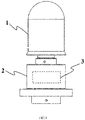
- FIG. 1 is a structural schematic diagram of a MEMS-based atmospheric electric field sensor on the ground according to an embodiment of the present invention.
- the MEMS-based atmospheric electric field sensor on the ground includes an arc-roof detection structure 1 and a MEMS electric field measuring module 3.
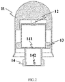
- FIG.2 is a cross-sectional schematic diagram of the arc-roof detection structure shown in FIG. 1 . As shown in FIG.
- the shape of the arc-roof detection structure 1 may be a cylinder, an elliptic cylinder, a cuboid, a cube, or other regular or irregular polyhedron etc.
- the arc-roof detection structure 1 includes an electric conducting arc-roof rainproof housing 11, an electric conducting binding post 12, a fixing-supporting chamber body upper part 13 and a fixing-supporting chamber body lower part 14.
- the top part of the electric conducting arc-roof rainproof housing 11 is arc-shaped, the bottom part of the electric conducting arc-roof rainproof housing 11 is provided with a groove facing towards the top part.
- the electric conducting binding post 12 is arranged at the top of the groove and is electrically connected to the arc-roof rainproof housing 11.
- the fixing-supporting chamber body upper part 13 is a cylinder with a closed top part and an open bottom part and arranged in the groove.
- the binding post 12 impenetrates the top part of the fixing-supporting chamber body upper part 13 and is electrically insulated from the fixing-supporting chamber body upper part 13.
- the fixing-supporting chamber body lower part 14 closes the bottom opening of the fixing-supporting chamber body upper part 13 to form a fixing-supporting chamber body.
- the MEMS electric field measuring module can be configured inside the fixing-supporting chamber body for detecting the external electric field through the electric conducting binding post 12 and electric conducting arc-roof rainproof housing 11.
- the electric conducting arc-roof rainproof housing 11, the electric conducting binding post 12, the arc-roof fixing-supporting chamber body upper part 13, and the arc-roof fixing-supporting chamber body lower part 14 are all electrical conductive and may be made of a metal material or an insulting material electroplated with metal on the inner surface, outer surface, or the inner and outer surface.
- the electric conducting arc-roof rainproof housing 11 which is electrically connected to the electric conducting binding post 12 is an isolated conductor.
- the electric conducting binding post 12 and the fixing-supporting chamber body upper part 13 are electrically isolated through an insulation and isolation structure.
- the material of the insulation and isolation structure can be an inorganic insulation material, an organic insulation material, or a mixed insulation material.
- the binding post 12 and the fixing-supporting chamber body upper part 13, the fixing-supporting chamber body upper part 13 and the fixing-supporting chamber body lower part 14 can be fixed together by screws or other fixing methods such as welding, bonding, etc..
- the MEMS-based atmospheric electric field sensor on the ground may further include a chamber body structure 2.
- the MEMS electric field measuring module 3 is disposed inside the chamber body structure 2, and detects the external electric field through the electric conducting binding post 12 and electric conducting arc-roof rainproof housing 11.
- FIG.3 is a cross-sectional schematic diagram of the chamber body structure shown in FIG. 1 .
- the chamber body structure 2 mainly includes a main housing 21 and a back cover 22.
- the shape of the chamber body structure 2 may be a cylinder, an elliptic cylinder, a cuboid, a cubic or other regular or irregular polyhedrons.
- the main housing 21 is a cylinder with a closed top part and an open bottom part.
- the top part of the main housing is provided with a first hole 211.
- the first hole 211 may be located at the center position or non-center position of the top part for introducing the conducting wire that electrically connected to the electric conducting binding post into the chamber body structure 2.
- the bottom opening of the fixing-supporting chamber body upper part 13 is closed, and the top part of the fixing-supporting chamber body lower part 14 is also provided with a second hole 141 in the center position or non-center position.
- the conducting wire electrically connected to the electric conducting binding post successively passes through the second hole 141 and the first hole 211.
- the back cover is used to close the bottom opening of the main housing 21.
- the chamber body structure 2 may be provided with sealing groove 24 and/or the glue-filling groove 25 which are respectively used to accommodate seal ring and fill seal glue.
- the sealing groove 24 and/or the glue-filling groove 25 may be disposed on at least one of the main housing 21 and the back cover 22, so that the main housing 21 and the back cover 22 are hermetically connected.
- the sealing groove 24 or glue-filling groove 25 may not be provided, and the glue is directly applied on the contact part of the main housing 21 and the back cover 22 of the seal chamber body for seal or the sealant is canned into the interior of the chamber body structure 2.
- the material of the seal ring may be fluororubber, silicone rubber, nitrile rubber etc.
- the sealant may be glass cement, AB glue, epoxy glue etc.
- the main housing 21 and the back cover 22 of the seal chamber body may also be fixed by screws.
- the arc-roof detection structure 1 and the chamber body structure 2 are fixed by screws.
- the fixing-supporting chamber body lower part 14 may be configured with a screw passing hole 142.
- the arc-roof detection structure 1 and the chamber body structure 2 may also be fixed by other methods such as welding, bonding, etc.
- the chamber body structure 2 may also be internally provided with a fixing post 23 for fixing and supporting the MEMS electric field measuring module 3 located in the chamber body structure 2.
- the fixing post 23 is fixedly connected to the back cover 22.
- the main housing 21, the back cover 22 and the fixing post 23 of the chamber body are all electrical conductive, and may be made of a metal material or an insulating material electroplated with metal on the inner surface or the outer surface or the inner and outer surfaces.
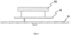
- FIG.4 is a structural schematic diagram of a MEMS electric field measuring module according to an embodiment of the present invention.
- the MEMS electric field measuring module 3 disposed in the fixing-supporting chamber body or the chamber body structure 2 mainly includes a MEMS electric field sensitive chip 31, pre-amplification circuit 32 and the driving demodulation circuit 33.
- the shape of the MEMS electric field measuring module 3 may be round, oval, rectangular, square or polygonal, etc.
- One or more MEMS electric field measuring module 3 may be mounted inside the fixing-supporting chamber body or the chamber body structure 2.
- the shielding electrode of the MEMS electric field sensitive chip 31 periodically vibrates and modulates the induction electrode to generate induced current.
- the package base-seat of the MEMS electric field sensitive chip 31 is made of an insulation material and the top part of the package of the MEMS electric field sensitive chip 31 is a metal cover plate.
- the pre-amplification circuit 32 is configured to realize the conversion from current signal into voltage signal of the electric field.
- the driving demodulation circuit 33 generates two-way differential signals required by the normal operation of the MEMS electric field sensitive chip 31 and realizes the electric field information calculation based on the voltage signal output by the pre-amplification circuit 32.
- the MEMS electric field sensitive chip 31, the pre-amplification circuit 32 and the driving demodulation circuit 33 are arranged in a stack-up manner and fixed at the fixing post 23 of the chamber body structure 2, and in other embodiments, they may be arranged horizontally or vertically in a side by side manner, etc.
- the metal cover plate at the top of the package of the MEMS electric field sensitive chip 31 is electrically connected to the electric conducting binding post 12 of the arc-roof detection structure 1 through conducting wires, so as to achieve the electrical connection with the arc-roof rainproof housing 11.
- the conducting wire may be a common conducting wire, a shielding wire, a high-frequency radio-frequency line, a semi-rigid semi-flexible radio-frequency cable etc.
- the operating principle of the MEMS-based atmospheric electric field sensor on the ground is as follows: since the arc-roof rainproof housing 11 of the sensor is electrically connected to the metal cover plate of the MEMS electric field sensitive chip 31, when a direct current (dc) electric field E exists in the exterior, the arc-roof rainproof housing 11 and the metal cover plate of the sensor produce induced charges and the production of induced charges is linearly correlated to the dc electric field E.
- the induced charges of the metal cover plate form an electric field E g , and E g is linearly correlated to the direct current electric field E.
- the MEMS electric field sensitive chip 31 indirectly measures the value of the external direct current electric field by measuring the electric field E g .
- the MEMS electric field measuring module 3 when the MEMS electric field measuring module 3 is disposed in the chamber body structure 2, the power supply cable and the signal transmission cable are leaded out through the third hole 222 configured at the back cover 22 of the seal chamber body structure, and the third hole 222 may be a central hole or a non-central hole.
- the chamber body structure 2 for accommodating the MEMS electric field measuring module 3 is sealed by the above-mentioned seal ring or sealant, and the cables pass through the third hole 222 of the back cover 22, a spin-coat of sealant should be performed to achieve the sealing of chamber.
- the fixing supporting chamber body formed by the fixing-supporting chamber body upper part 13 and the fixing-supporting chamber body lower part 14 also needs to be configured hermetically
- the contact position of the fixing-supporting chamber body upper part 13 and the fixing-supporting chamber body lower part 14 may be spin-coated with sealant, or a sealant is directly canned into the fixing-supporting chamber body.
- the sealant may be the glass cement, silicone rubber, AB glue, epoxy glue etc. Since the electric conducting binding post 12 is located close to the metal cover plate of the MEMS electric field sensitive chip 31, charges can be induced on the metal cover plate corresponding to the electric conducting binding post 12.
- the electric conducting binding post 12 may or may not electrically connected to the metal cover plate of the MEMS electric field sensitive chip 31.
- FIG. 5 is a structural schematic diagram of a MEMS electric field measuring module according to another embodiment of the present invention.
- the MEMS electric field measuring module 3 further includes an insulation seal box 34.
- the MEMS electric field sensitive chip 31 and the pre-amplification circuit 32 which are arranged in stack-up manner are put into the insulation seal box 34 first.
- the top part of the seal box body 341 is provided with a metal sensing board 342.
- the metal sensing board 342 is fixedly connected to the seal box body 341.
- the shape of the insulation seal box 34 may be a cylinder, an elliptic cylinder, a cuboid, a cube or other regular or irregular polyhedrons.
- the seal box body 341 may be made of inorganic insulation materials, organic insulation materials or mixed insulation materials.
- the insulation seal box 34 and the driving demodulation circuit 33 are arranged in a stack-up -manner. After the signal connecting wire of the driving demodulation circuit 33 and the pre-amplification circuit 32 passes out of the signal output interface of the insulation seal box 34, the signal output interface is spin-coated with sealant, so as to realize the sealing.
- the driving demodulation circuit 33 can also be arranged inside the insulation seal box 34 together with the electric field sensitive chip 31 and the pre-amplification circuit 32. Different from the solution where the metal cover plate of the MEMS electric field sensitive chip 31 is electrically connected to the arc-roof rainproof housing 11 shown in Fig.
- the conducting wire may be a common conducting wire, a shielding conducting wire, a high-frequency radio-frequency cable, a semi-rigid semi-flexible radio-frequency cable, etc.
- the operating principle of the MEMS-based atmospheric electric field sensor on the ground is as follows. Since the arc-roof rainproof housing 11 of the sensor is electrically connected to the metal sensing board 342 above the seal box body 341 while a capacitor structure is formed between the metal sensing board 342 and the metal cover plate of the MEMS electric field sensitive chip, when a dc electric field E exists in the exterior, induced charges will be produced in the metal cover plate. These induced charges generate an electric field E d , and the electric field E d is linearly correlated to the direct current electric field E, so that the MEMS electric field sensitive chip 31 can indirectly measure the external dc electric field E by measuring the electric field E d .
- the fixing-supporting chamber body or the chamber body structure 2 for accommodating the MEMS electric field measuring module 3 may not be sealed.
- the desiccant or other kind of hygroscopic material may be placed inside the sealed chamber body structure 2, the insulation seal box 34, or the sealed fixing-supporting chamber body to ensure the dryness in the sealed environment, so as to prevent the components of the MEMS electric field measuring module from being corroded, thereby ensuring its working performances.
- the MEMS-based atmospheric electric field sensor on the ground may also be fixed on a metal bracket to measure the atmospheric electric field.
- the MEMS-based atmospheric electric field sensor on the ground may be mounted on the metal bracket through mounting holes 223 at the bottom of the chamber body structure 2, the metal bracket is electrically connected to the chamber body structure 2, and the metal bracket may be grounded to prevent the chamber body structure 2 from gathering too much charges.
- the metal bracket may not be grounded, and the bracket may also be made of other materials, such as wood, plastic, etc.
- the bracket may not be used, the MEMS-based atmospheric electric field sensor on the ground is directly mounted on some devices or placed on the ground to perform the electric field measurement.
- the MEMS-based atmospheric electric field sensor on the ground may also be applied in lightning pre-warning, industrial electrostatic measurement, dc electric field measurement of power grid and related electrostatic field measurement devices.
Landscapes
- Environmental & Geological Engineering (AREA)
- Physics & Mathematics (AREA)
- General Physics & Mathematics (AREA)
- Engineering & Computer Science (AREA)
- Life Sciences & Earth Sciences (AREA)
- Atmospheric Sciences (AREA)
- Biodiversity & Conservation Biology (AREA)
- Ecology (AREA)
- Environmental Sciences (AREA)
- Testing Or Calibration Of Command Recording Devices (AREA)
- Micromachines (AREA)
- Investigating Or Analyzing Materials By The Use Of Electric Means (AREA)
Applications Claiming Priority (2)
| Application Number | Priority Date | Filing Date | Title |
|---|---|---|---|
| CN201710401997 | 2017-05-31 | ||
| PCT/CN2018/077780 WO2018219002A1 (fr) | 2017-05-31 | 2018-03-01 | Capteur de champ électrique atmosphérique au sol mems |
Publications (3)
| Publication Number | Publication Date |
|---|---|
| EP3441776A1 true EP3441776A1 (fr) | 2019-02-13 |
| EP3441776A4 EP3441776A4 (fr) | 2019-08-14 |
| EP3441776B1 EP3441776B1 (fr) | 2022-07-27 |
Family
ID=60132715
Family Applications (1)
| Application Number | Title | Priority Date | Filing Date |
|---|---|---|---|
| EP18714420.9A Active EP3441776B1 (fr) | 2017-05-31 | 2018-03-01 | Capteur de champ électrique atmosphérique mems au sol |
Country Status (4)
| Country | Link |
|---|---|
| US (1) | US10718802B2 (fr) |
| EP (1) | EP3441776B1 (fr) |
| CN (1) | CN107300642B (fr) |
| WO (1) | WO2018219002A1 (fr) |
Families Citing this family (11)
| Publication number | Priority date | Publication date | Assignee | Title |
|---|---|---|---|---|
| CN107300642B (zh) * | 2017-05-31 | 2023-11-07 | 北京中科飞龙传感技术有限责任公司 | Mems地面大气电场传感器 |
| CN113933913B (zh) * | 2020-06-29 | 2024-07-26 | 中国石油天然气集团有限公司 | 油罐雷电预警装置 |
| CN113125894A (zh) * | 2021-05-14 | 2021-07-16 | 国网陕西省电力公司电力科学研究院 | 一种变压器电场检测装置封装结构 |
| CN114184853B (zh) * | 2021-12-14 | 2024-08-20 | 中国电力科学研究院有限公司 | 一种工频电场测量装置 |
| CN115184696B (zh) * | 2022-07-11 | 2025-03-21 | 中国科学院空天信息创新研究院 | 一种芯片级三维电场传感器及其测量方法 |
| CN115184697B (zh) * | 2022-07-11 | 2025-03-18 | 中国科学院空天信息创新研究院 | 一种空间三维电场测量传感器及其测量方法 |
| CN115290993B (zh) * | 2022-10-10 | 2023-01-13 | 中国科学院空天信息创新研究院 | 一种球形电极全向静电场检测装置 |
| CN116247603B (zh) * | 2023-02-17 | 2024-03-19 | 国网江西省电力有限公司南昌供电分公司 | 一种高安全性支柱式避雷器 |
| CN118169480B (zh) * | 2024-03-29 | 2025-04-08 | 北京中科飞龙传感技术有限责任公司 | Mems大气电场传感器及其组装方法 |
| CN118549716B (zh) * | 2024-07-30 | 2024-10-11 | 云南师范大学 | 一种电子式大气电场测量设备及方法 |
| CN120522464B (zh) * | 2025-07-24 | 2025-10-10 | 温州安能科技有限公司 | 一种机载非接触式验电装置及验电方法 |
Family Cites Families (18)
| Publication number | Priority date | Publication date | Assignee | Title |
|---|---|---|---|---|
| US3919636A (en) * | 1974-04-29 | 1975-11-11 | Us Navy | Electrical field change meter |
| US3925726A (en) * | 1974-05-08 | 1975-12-09 | Us Navy | Electric field sensor |
| US3916305A (en) * | 1974-05-20 | 1975-10-28 | Us Navy | Atmospheric electrical current detector |
| FR2476849A1 (fr) * | 1980-02-22 | 1981-08-28 | Onera (Off Nat Aerospatiale) | Appareil pour la mesure d'un champ electrique |
| US7924018B2 (en) * | 2008-12-19 | 2011-04-12 | Illinois Tool Works Inc. | MEMS electrometer that measures amount of repulsion of adjacent beams from each other for static field detection |
| CN102937671A (zh) * | 2012-10-24 | 2013-02-20 | 中国人民解放军理工大学气象学院 | 一种雷电及地面电场监测一体装置 |
| CN103633036B (zh) * | 2013-08-07 | 2017-03-08 | 中国科学院电子学研究所 | 基于高阻材料的电场传感器封装元件 |
| CN103983863A (zh) * | 2014-05-30 | 2014-08-13 | 唐凯 | 一种微型化雷电预警装置 |
| US9880120B2 (en) * | 2014-07-22 | 2018-01-30 | The United States Of America As Represented By The Secretary Of The Army | Electric field sensor |
| CN204479659U (zh) * | 2015-03-17 | 2015-07-15 | 江苏省无线电科学研究所有限公司 | 低功耗一体式大气电场传感器 |
| CN105954602B (zh) * | 2016-05-23 | 2018-06-26 | 厦门大恒科技有限公司 | 一种大气电场信号跟随式测试仪及其测试方法 |
| CN106124870B (zh) * | 2016-06-12 | 2019-12-20 | 中国科学院电子学研究所 | 电极型电场传感器封装元件及其用途 |
| CN206038938U (zh) * | 2016-08-12 | 2017-03-22 | 南京大桥机器有限公司 | 一种mems电场探空仪系统 |
| CN106597065A (zh) * | 2016-12-10 | 2017-04-26 | 国网浙江省电力公司金华供电公司 | Mems非接触式高压直流验电器 |
| CN106672890B (zh) * | 2016-12-13 | 2018-12-04 | 北京中科飞龙传感技术有限责任公司 | 一种灵敏度增强型电场传感器的封装盖板及封装方法 |
| CN106707038A (zh) * | 2017-02-17 | 2017-05-24 | 北京中自控创新科技发展有限公司 | 一种本地及远程探测相结合的一体式雷电预警组合探头及其探测方法 |
| CN206906494U (zh) * | 2017-05-31 | 2018-01-19 | 北京中科飞龙传感技术有限责任公司 | Mems地面大气电场传感器 |
| CN107300642B (zh) * | 2017-05-31 | 2023-11-07 | 北京中科飞龙传感技术有限责任公司 | Mems地面大气电场传感器 |
-
2017
- 2017-07-10 CN CN201710555617.3A patent/CN107300642B/zh active Active
-
2018
- 2018-03-01 WO PCT/CN2018/077780 patent/WO2018219002A1/fr not_active Ceased
- 2018-03-01 EP EP18714420.9A patent/EP3441776B1/fr active Active
- 2018-05-30 US US15/992,214 patent/US10718802B2/en active Active
Also Published As
| Publication number | Publication date |
|---|---|
| EP3441776A4 (fr) | 2019-08-14 |
| CN107300642A (zh) | 2017-10-27 |
| US10718802B2 (en) | 2020-07-21 |
| CN107300642B (zh) | 2023-11-07 |
| WO2018219002A1 (fr) | 2018-12-06 |
| US20190094283A1 (en) | 2019-03-28 |
| EP3441776B1 (fr) | 2022-07-27 |
Similar Documents
| Publication | Publication Date | Title |
|---|---|---|
| US10718802B2 (en) | MEMS-based atmospheric electric field sensor on the ground | |
| KR101077441B1 (ko) | 초고주파 진동센서를 이용한 실시간 열화 감지장치 및 이를 이용한 배전반 | |
| CN107015072B (zh) | 一种基于电场传感器的密封型非接触式手持静电仪 | |
| CN107228989B (zh) | 一种绝缘密封结构的mems电场传感器 | |
| CN107946478B (zh) | 封装结构及其制作方法、封装缺陷检测方法、oled器件和显示装置 | |
| CN107219027A (zh) | 一种陶瓷电容压力传感器的封装结构 | |
| CN106124870A (zh) | 电极型电场传感器封装元件及其用途 | |
| CN205484666U (zh) | 一种内置式超声波局放传感器 | |
| CN210639115U (zh) | 一种防爆露点仪 | |
| CN106483436A (zh) | 用于电力设备局部放电检测的多用途外置特高频传感器 | |
| CN208953519U (zh) | 一种新型茶叶品质检测收集装置 | |
| CN207249002U (zh) | 球载式mems探空电场传感器及其集成系统 | |
| CN206906494U (zh) | Mems地面大气电场传感器 | |
| CN201440086U (zh) | 一种浸水探测装置 | |
| CN101568983A (zh) | 改进的耦合器 | |
| CN208187653U (zh) | 一种防水产品的ip67无水检测装置 | |
| CN103217633A (zh) | 一种用于高压开关柜局部放电检测的传感器 | |
| CN106290572A (zh) | 一种变电站绝缘子无线带电探伤仪 | |
| CN206891621U (zh) | 一种陶瓷电容压力传感器的封装结构 | |
| CN206960517U (zh) | 一种灵敏度增强型电场传感器的封装盖板 | |
| CN207215173U (zh) | 一种用于监测井盖破损、丢失和车流量的传感器 | |
| CN213874482U (zh) | 用于变电站在线监测的无线智能传感器 | |
| CN206684262U (zh) | 电力设备局部放电检测的非接触式智能超声波传感器 | |
| CN203024887U (zh) | 一种支架式测温器 | |
| CN212622389U (zh) | 用于管道腐蚀监测/检测系统的防爆箱体 |
Legal Events
| Date | Code | Title | Description |
|---|---|---|---|
| STAA | Information on the status of an ep patent application or granted ep patent |
Free format text: STATUS: UNKNOWN |
|
| STAA | Information on the status of an ep patent application or granted ep patent |
Free format text: STATUS: THE INTERNATIONAL PUBLICATION HAS BEEN MADE |
|
| PUAI | Public reference made under article 153(3) epc to a published international application that has entered the european phase |
Free format text: ORIGINAL CODE: 0009012 |
|
| STAA | Information on the status of an ep patent application or granted ep patent |
Free format text: STATUS: REQUEST FOR EXAMINATION WAS MADE |
|
| 17P | Request for examination filed |
Effective date: 20180412 |
|
| AK | Designated contracting states |
Kind code of ref document: A1 Designated state(s): AL AT BE BG CH CY CZ DE DK EE ES FI FR GB GR HR HU IE IS IT LI LT LU LV MC MK MT NL NO PL PT RO RS SE SI SK SM TR |
|
| AX | Request for extension of the european patent |
Extension state: BA ME |
|
| RIN1 | Information on inventor provided before grant (corrected) |
Inventor name: WU, SHUANG Inventor name: YANG, PENGFEI Inventor name: PENG, CHUNRONG Inventor name: LIU, YUTAO Inventor name: XIA, SHANHONG |
|
| RIC1 | Information provided on ipc code assigned before grant |
Ipc: G01R 29/12 20060101AFI20190704BHEP |
|
| A4 | Supplementary search report drawn up and despatched |
Effective date: 20190712 |
|
| DAV | Request for validation of the european patent (deleted) | ||
| DAX | Request for extension of the european patent (deleted) | ||
| STAA | Information on the status of an ep patent application or granted ep patent |
Free format text: STATUS: EXAMINATION IS IN PROGRESS |
|
| 17Q | First examination report despatched |
Effective date: 20210310 |
|
| GRAP | Despatch of communication of intention to grant a patent |
Free format text: ORIGINAL CODE: EPIDOSNIGR1 |
|
| STAA | Information on the status of an ep patent application or granted ep patent |
Free format text: STATUS: GRANT OF PATENT IS INTENDED |
|
| RIC1 | Information provided on ipc code assigned before grant |
Ipc: G01W 1/16 20060101ALI20220429BHEP Ipc: G01R 29/12 20060101AFI20220429BHEP |
|
| GRAS | Grant fee paid |
Free format text: ORIGINAL CODE: EPIDOSNIGR3 |
|
| INTG | Intention to grant announced |
Effective date: 20220523 |
|
| GRAA | (expected) grant |
Free format text: ORIGINAL CODE: 0009210 |
|
| STAA | Information on the status of an ep patent application or granted ep patent |
Free format text: STATUS: THE PATENT HAS BEEN GRANTED |
|
| AK | Designated contracting states |
Kind code of ref document: B1 Designated state(s): AL AT BE BG CH CY CZ DE DK EE ES FI FR GB GR HR HU IE IS IT LI LT LU LV MC MK MT NL NO PL PT RO RS SE SI SK SM TR |
|
| REG | Reference to a national code |
Ref country code: CH Ref legal event code: EP |
|
| REG | Reference to a national code |
Ref country code: AT Ref legal event code: REF Ref document number: 1507408 Country of ref document: AT Kind code of ref document: T Effective date: 20220815 |
|
| REG | Reference to a national code |
Ref country code: DE Ref legal event code: R096 Ref document number: 602018038421 Country of ref document: DE |
|
| REG | Reference to a national code |
Ref country code: IE Ref legal event code: FG4D |
|
| REG | Reference to a national code |
Ref country code: LT Ref legal event code: MG9D |
|
| REG | Reference to a national code |
Ref country code: NL Ref legal event code: MP Effective date: 20220727 |
|
| PG25 | Lapsed in a contracting state [announced via postgrant information from national office to epo] |
Ref country code: SE Free format text: LAPSE BECAUSE OF FAILURE TO SUBMIT A TRANSLATION OF THE DESCRIPTION OR TO PAY THE FEE WITHIN THE PRESCRIBED TIME-LIMIT Effective date: 20220727 Ref country code: RS Free format text: LAPSE BECAUSE OF FAILURE TO SUBMIT A TRANSLATION OF THE DESCRIPTION OR TO PAY THE FEE WITHIN THE PRESCRIBED TIME-LIMIT Effective date: 20220727 Ref country code: PT Free format text: LAPSE BECAUSE OF FAILURE TO SUBMIT A TRANSLATION OF THE DESCRIPTION OR TO PAY THE FEE WITHIN THE PRESCRIBED TIME-LIMIT Effective date: 20221128 Ref country code: NO Free format text: LAPSE BECAUSE OF FAILURE TO SUBMIT A TRANSLATION OF THE DESCRIPTION OR TO PAY THE FEE WITHIN THE PRESCRIBED TIME-LIMIT Effective date: 20221027 Ref country code: NL Free format text: LAPSE BECAUSE OF FAILURE TO SUBMIT A TRANSLATION OF THE DESCRIPTION OR TO PAY THE FEE WITHIN THE PRESCRIBED TIME-LIMIT Effective date: 20220727 Ref country code: LV Free format text: LAPSE BECAUSE OF FAILURE TO SUBMIT A TRANSLATION OF THE DESCRIPTION OR TO PAY THE FEE WITHIN THE PRESCRIBED TIME-LIMIT Effective date: 20220727 Ref country code: LT Free format text: LAPSE BECAUSE OF FAILURE TO SUBMIT A TRANSLATION OF THE DESCRIPTION OR TO PAY THE FEE WITHIN THE PRESCRIBED TIME-LIMIT Effective date: 20220727 Ref country code: FI Free format text: LAPSE BECAUSE OF FAILURE TO SUBMIT A TRANSLATION OF THE DESCRIPTION OR TO PAY THE FEE WITHIN THE PRESCRIBED TIME-LIMIT Effective date: 20220727 Ref country code: ES Free format text: LAPSE BECAUSE OF FAILURE TO SUBMIT A TRANSLATION OF THE DESCRIPTION OR TO PAY THE FEE WITHIN THE PRESCRIBED TIME-LIMIT Effective date: 20220727 |
|
| REG | Reference to a national code |
Ref country code: AT Ref legal event code: MK05 Ref document number: 1507408 Country of ref document: AT Kind code of ref document: T Effective date: 20220727 |
|
| PG25 | Lapsed in a contracting state [announced via postgrant information from national office to epo] |
Ref country code: PL Free format text: LAPSE BECAUSE OF FAILURE TO SUBMIT A TRANSLATION OF THE DESCRIPTION OR TO PAY THE FEE WITHIN THE PRESCRIBED TIME-LIMIT Effective date: 20220727 Ref country code: IS Free format text: LAPSE BECAUSE OF FAILURE TO SUBMIT A TRANSLATION OF THE DESCRIPTION OR TO PAY THE FEE WITHIN THE PRESCRIBED TIME-LIMIT Effective date: 20221127 Ref country code: HR Free format text: LAPSE BECAUSE OF FAILURE TO SUBMIT A TRANSLATION OF THE DESCRIPTION OR TO PAY THE FEE WITHIN THE PRESCRIBED TIME-LIMIT Effective date: 20220727 Ref country code: GR Free format text: LAPSE BECAUSE OF FAILURE TO SUBMIT A TRANSLATION OF THE DESCRIPTION OR TO PAY THE FEE WITHIN THE PRESCRIBED TIME-LIMIT Effective date: 20221028 |
|
| PG25 | Lapsed in a contracting state [announced via postgrant information from national office to epo] |
Ref country code: SM Free format text: LAPSE BECAUSE OF FAILURE TO SUBMIT A TRANSLATION OF THE DESCRIPTION OR TO PAY THE FEE WITHIN THE PRESCRIBED TIME-LIMIT Effective date: 20220727 Ref country code: RO Free format text: LAPSE BECAUSE OF FAILURE TO SUBMIT A TRANSLATION OF THE DESCRIPTION OR TO PAY THE FEE WITHIN THE PRESCRIBED TIME-LIMIT Effective date: 20220727 Ref country code: DK Free format text: LAPSE BECAUSE OF FAILURE TO SUBMIT A TRANSLATION OF THE DESCRIPTION OR TO PAY THE FEE WITHIN THE PRESCRIBED TIME-LIMIT Effective date: 20220727 Ref country code: CZ Free format text: LAPSE BECAUSE OF FAILURE TO SUBMIT A TRANSLATION OF THE DESCRIPTION OR TO PAY THE FEE WITHIN THE PRESCRIBED TIME-LIMIT Effective date: 20220727 Ref country code: AT Free format text: LAPSE BECAUSE OF FAILURE TO SUBMIT A TRANSLATION OF THE DESCRIPTION OR TO PAY THE FEE WITHIN THE PRESCRIBED TIME-LIMIT Effective date: 20220727 |
|
| REG | Reference to a national code |
Ref country code: DE Ref legal event code: R097 Ref document number: 602018038421 Country of ref document: DE |
|
| PG25 | Lapsed in a contracting state [announced via postgrant information from national office to epo] |
Ref country code: SK Free format text: LAPSE BECAUSE OF FAILURE TO SUBMIT A TRANSLATION OF THE DESCRIPTION OR TO PAY THE FEE WITHIN THE PRESCRIBED TIME-LIMIT Effective date: 20220727 Ref country code: EE Free format text: LAPSE BECAUSE OF FAILURE TO SUBMIT A TRANSLATION OF THE DESCRIPTION OR TO PAY THE FEE WITHIN THE PRESCRIBED TIME-LIMIT Effective date: 20220727 |
|
| PLBE | No opposition filed within time limit |
Free format text: ORIGINAL CODE: 0009261 |
|
| STAA | Information on the status of an ep patent application or granted ep patent |
Free format text: STATUS: NO OPPOSITION FILED WITHIN TIME LIMIT |
|
| PG25 | Lapsed in a contracting state [announced via postgrant information from national office to epo] |
Ref country code: AL Free format text: LAPSE BECAUSE OF FAILURE TO SUBMIT A TRANSLATION OF THE DESCRIPTION OR TO PAY THE FEE WITHIN THE PRESCRIBED TIME-LIMIT Effective date: 20220727 |
|
| 26N | No opposition filed |
Effective date: 20230502 |
|
| PG25 | Lapsed in a contracting state [announced via postgrant information from national office to epo] |
Ref country code: SI Free format text: LAPSE BECAUSE OF FAILURE TO SUBMIT A TRANSLATION OF THE DESCRIPTION OR TO PAY THE FEE WITHIN THE PRESCRIBED TIME-LIMIT Effective date: 20220727 |
|
| PG25 | Lapsed in a contracting state [announced via postgrant information from national office to epo] |
Ref country code: MC Free format text: LAPSE BECAUSE OF FAILURE TO SUBMIT A TRANSLATION OF THE DESCRIPTION OR TO PAY THE FEE WITHIN THE PRESCRIBED TIME-LIMIT Effective date: 20220727 |
|
| REG | Reference to a national code |
Ref country code: CH Ref legal event code: PL |
|
| REG | Reference to a national code |
Ref country code: BE Ref legal event code: MM Effective date: 20230331 |
|
| PG25 | Lapsed in a contracting state [announced via postgrant information from national office to epo] |
Ref country code: LU Free format text: LAPSE BECAUSE OF NON-PAYMENT OF DUE FEES Effective date: 20230301 |
|
| REG | Reference to a national code |
Ref country code: IE Ref legal event code: MM4A |
|
| PG25 | Lapsed in a contracting state [announced via postgrant information from national office to epo] |
Ref country code: LI Free format text: LAPSE BECAUSE OF NON-PAYMENT OF DUE FEES Effective date: 20230331 Ref country code: IE Free format text: LAPSE BECAUSE OF NON-PAYMENT OF DUE FEES Effective date: 20230301 Ref country code: CH Free format text: LAPSE BECAUSE OF NON-PAYMENT OF DUE FEES Effective date: 20230331 |
|
| PG25 | Lapsed in a contracting state [announced via postgrant information from national office to epo] |
Ref country code: BE Free format text: LAPSE BECAUSE OF NON-PAYMENT OF DUE FEES Effective date: 20230331 |
|
| PG25 | Lapsed in a contracting state [announced via postgrant information from national office to epo] |
Ref country code: IT Free format text: LAPSE BECAUSE OF FAILURE TO SUBMIT A TRANSLATION OF THE DESCRIPTION OR TO PAY THE FEE WITHIN THE PRESCRIBED TIME-LIMIT Effective date: 20220727 |
|
| PG25 | Lapsed in a contracting state [announced via postgrant information from national office to epo] |
Ref country code: BG Free format text: LAPSE BECAUSE OF FAILURE TO SUBMIT A TRANSLATION OF THE DESCRIPTION OR TO PAY THE FEE WITHIN THE PRESCRIBED TIME-LIMIT Effective date: 20220727 |
|
| PG25 | Lapsed in a contracting state [announced via postgrant information from national office to epo] |
Ref country code: BG Free format text: LAPSE BECAUSE OF FAILURE TO SUBMIT A TRANSLATION OF THE DESCRIPTION OR TO PAY THE FEE WITHIN THE PRESCRIBED TIME-LIMIT Effective date: 20220727 |
|
| PG25 | Lapsed in a contracting state [announced via postgrant information from national office to epo] |
Ref country code: CY Free format text: LAPSE BECAUSE OF FAILURE TO SUBMIT A TRANSLATION OF THE DESCRIPTION OR TO PAY THE FEE WITHIN THE PRESCRIBED TIME-LIMIT; INVALID AB INITIO Effective date: 20180301 |
|
| PG25 | Lapsed in a contracting state [announced via postgrant information from national office to epo] |
Ref country code: HU Free format text: LAPSE BECAUSE OF FAILURE TO SUBMIT A TRANSLATION OF THE DESCRIPTION OR TO PAY THE FEE WITHIN THE PRESCRIBED TIME-LIMIT; INVALID AB INITIO Effective date: 20180301 |
|
| PG25 | Lapsed in a contracting state [announced via postgrant information from national office to epo] |
Ref country code: TR Free format text: LAPSE BECAUSE OF FAILURE TO SUBMIT A TRANSLATION OF THE DESCRIPTION OR TO PAY THE FEE WITHIN THE PRESCRIBED TIME-LIMIT Effective date: 20220727 |
|
| PGFP | Annual fee paid to national office [announced via postgrant information from national office to epo] |
Ref country code: GB Payment date: 20260226 Year of fee payment: 9 |
|
| PGFP | Annual fee paid to national office [announced via postgrant information from national office to epo] |
Ref country code: DE Payment date: 20260310 Year of fee payment: 9 |
|
| PGFP | Annual fee paid to national office [announced via postgrant information from national office to epo] |
Ref country code: FR Payment date: 20260226 Year of fee payment: 9 |