EP3441906B1 - Informationsverarbeitungsvorrichtung, bewegtes objekt, informationsverarbeitungsverfahren und computerlesbares medium - Google Patents
Informationsverarbeitungsvorrichtung, bewegtes objekt, informationsverarbeitungsverfahren und computerlesbares medium Download PDFInfo
- Publication number
- EP3441906B1 EP3441906B1 EP18159701.4A EP18159701A EP3441906B1 EP 3441906 B1 EP3441906 B1 EP 3441906B1 EP 18159701 A EP18159701 A EP 18159701A EP 3441906 B1 EP3441906 B1 EP 3441906B1
- Authority
- EP
- European Patent Office
- Prior art keywords
- distribution
- probability distribution
- measurement
- sensor
- occupancy level
- Prior art date
- Legal status (The legal status is an assumption and is not a legal conclusion. Google has not performed a legal analysis and makes no representation as to the accuracy of the status listed.)
- Active
Links
Images




Classifications
-
- G—PHYSICS
- G01—MEASURING; TESTING
- G01S—RADIO DIRECTION-FINDING; RADIO NAVIGATION; DETERMINING DISTANCE OR VELOCITY BY USE OF RADIO WAVES; LOCATING OR PRESENCE-DETECTING BY USE OF THE REFLECTION OR RERADIATION OF RADIO WAVES; ANALOGOUS ARRANGEMENTS USING OTHER WAVES
- G01S7/00—Details of systems according to groups G01S13/00, G01S15/00, G01S17/00
- G01S7/02—Details of systems according to groups G01S13/00, G01S15/00, G01S17/00 of systems according to group G01S13/00
- G01S7/40—Means for monitoring or calibrating
- G01S7/4004—Means for monitoring or calibrating of parts of a radar system
- G01S7/4026—Antenna boresight
-
- G—PHYSICS
- G01—MEASURING; TESTING
- G01S—RADIO DIRECTION-FINDING; RADIO NAVIGATION; DETERMINING DISTANCE OR VELOCITY BY USE OF RADIO WAVES; LOCATING OR PRESENCE-DETECTING BY USE OF THE REFLECTION OR RERADIATION OF RADIO WAVES; ANALOGOUS ARRANGEMENTS USING OTHER WAVES
- G01S17/00—Systems using the reflection or reradiation of electromagnetic waves other than radio waves, e.g. lidar systems
- G01S17/88—Lidar systems specially adapted for specific applications
- G01S17/93—Lidar systems specially adapted for specific applications for anti-collision purposes
- G01S17/931—Lidar systems specially adapted for specific applications for anti-collision purposes of land vehicles
-
- G—PHYSICS
- G01—MEASURING; TESTING
- G01S—RADIO DIRECTION-FINDING; RADIO NAVIGATION; DETERMINING DISTANCE OR VELOCITY BY USE OF RADIO WAVES; LOCATING OR PRESENCE-DETECTING BY USE OF THE REFLECTION OR RERADIATION OF RADIO WAVES; ANALOGOUS ARRANGEMENTS USING OTHER WAVES
- G01S7/00—Details of systems according to groups G01S13/00, G01S15/00, G01S17/00
- G01S7/48—Details of systems according to groups G01S13/00, G01S15/00, G01S17/00 of systems according to group G01S17/00
- G01S7/497—Means for monitoring or calibrating
-
- G—PHYSICS
- G01—MEASURING; TESTING
- G01S—RADIO DIRECTION-FINDING; RADIO NAVIGATION; DETERMINING DISTANCE OR VELOCITY BY USE OF RADIO WAVES; LOCATING OR PRESENCE-DETECTING BY USE OF THE REFLECTION OR RERADIATION OF RADIO WAVES; ANALOGOUS ARRANGEMENTS USING OTHER WAVES
- G01S7/00—Details of systems according to groups G01S13/00, G01S15/00, G01S17/00
- G01S7/52—Details of systems according to groups G01S13/00, G01S15/00, G01S17/00 of systems according to group G01S15/00
- G01S7/52004—Means for monitoring or calibrating
-
- G—PHYSICS
- G06—COMPUTING OR CALCULATING; COUNTING
- G06F—ELECTRIC DIGITAL DATA PROCESSING
- G06F18/00—Pattern recognition
- G06F18/20—Analysing
- G06F18/24—Classification techniques
- G06F18/241—Classification techniques relating to the classification model, e.g. parametric or non-parametric approaches
- G06F18/2415—Classification techniques relating to the classification model, e.g. parametric or non-parametric approaches based on parametric or probabilistic models, e.g. based on likelihood ratio or false acceptance rate versus a false rejection rate
-
- G—PHYSICS
- G06—COMPUTING OR CALCULATING; COUNTING
- G06T—IMAGE DATA PROCESSING OR GENERATION, IN GENERAL
- G06T7/00—Image analysis
- G06T7/70—Determining position or orientation of objects or cameras
- G06T7/77—Determining position or orientation of objects or cameras using statistical methods
-
- G—PHYSICS
- G06—COMPUTING OR CALCULATING; COUNTING
- G06V—IMAGE OR VIDEO RECOGNITION OR UNDERSTANDING
- G06V10/00—Arrangements for image or video recognition or understanding
- G06V10/20—Image preprocessing
- G06V10/255—Detecting or recognising potential candidate objects based on visual cues, e.g. shapes
-
- G—PHYSICS
- G06—COMPUTING OR CALCULATING; COUNTING
- G06V—IMAGE OR VIDEO RECOGNITION OR UNDERSTANDING
- G06V10/00—Arrangements for image or video recognition or understanding
- G06V10/70—Arrangements for image or video recognition or understanding using pattern recognition or machine learning
- G06V10/764—Arrangements for image or video recognition or understanding using pattern recognition or machine learning using classification, e.g. of video objects
-
- G—PHYSICS
- G06—COMPUTING OR CALCULATING; COUNTING
- G06V—IMAGE OR VIDEO RECOGNITION OR UNDERSTANDING
- G06V20/00—Scenes; Scene-specific elements
- G06V20/50—Context or environment of the image
- G06V20/52—Surveillance or monitoring of activities, e.g. for recognising suspicious objects
-
- G—PHYSICS
- G06—COMPUTING OR CALCULATING; COUNTING
- G06V—IMAGE OR VIDEO RECOGNITION OR UNDERSTANDING
- G06V20/00—Scenes; Scene-specific elements
- G06V20/50—Context or environment of the image
- G06V20/56—Context or environment of the image exterior to a vehicle by using sensors mounted on the vehicle
- G06V20/58—Recognition of moving objects or obstacles, e.g. vehicles or pedestrians; Recognition of traffic objects, e.g. traffic signs, traffic lights or roads
-
- G—PHYSICS
- G08—SIGNALLING
- G08G—TRAFFIC CONTROL SYSTEMS
- G08G1/00—Traffic control systems for road vehicles
- G08G1/01—Detecting movement of traffic to be counted or controlled
- G08G1/0104—Measuring and analyzing of parameters relative to traffic conditions
- G08G1/0108—Measuring and analyzing of parameters relative to traffic conditions based on the source of data
- G08G1/0112—Measuring and analyzing of parameters relative to traffic conditions based on the source of data from the vehicle, e.g. floating car data [FCD]
-
- G—PHYSICS
- G08—SIGNALLING
- G08G—TRAFFIC CONTROL SYSTEMS
- G08G1/00—Traffic control systems for road vehicles
- G08G1/16—Anti-collision systems
- G08G1/165—Anti-collision systems for passive traffic, e.g. including static obstacles, trees
-
- G—PHYSICS
- G08—SIGNALLING
- G08G—TRAFFIC CONTROL SYSTEMS
- G08G1/00—Traffic control systems for road vehicles
- G08G1/16—Anti-collision systems
- G08G1/166—Anti-collision systems for active traffic, e.g. moving vehicles, pedestrians, bikes
-
- G—PHYSICS
- G01—MEASURING; TESTING
- G01S—RADIO DIRECTION-FINDING; RADIO NAVIGATION; DETERMINING DISTANCE OR VELOCITY BY USE OF RADIO WAVES; LOCATING OR PRESENCE-DETECTING BY USE OF THE REFLECTION OR RERADIATION OF RADIO WAVES; ANALOGOUS ARRANGEMENTS USING OTHER WAVES
- G01S13/00—Systems using the reflection or reradiation of radio waves, e.g. radar systems; Analogous systems using reflection or reradiation of waves whose nature or wavelength is irrelevant or unspecified
- G01S13/86—Combinations of radar systems with non-radar systems, e.g. sonar, direction finder
-
- G—PHYSICS
- G01—MEASURING; TESTING
- G01S—RADIO DIRECTION-FINDING; RADIO NAVIGATION; DETERMINING DISTANCE OR VELOCITY BY USE OF RADIO WAVES; LOCATING OR PRESENCE-DETECTING BY USE OF THE REFLECTION OR RERADIATION OF RADIO WAVES; ANALOGOUS ARRANGEMENTS USING OTHER WAVES
- G01S15/00—Systems using the reflection or reradiation of acoustic waves, e.g. sonar systems
- G01S15/86—Combinations of sonar systems with lidar systems; Combinations of sonar systems with systems not using wave reflection
-
- G—PHYSICS
- G01—MEASURING; TESTING
- G01S—RADIO DIRECTION-FINDING; RADIO NAVIGATION; DETERMINING DISTANCE OR VELOCITY BY USE OF RADIO WAVES; LOCATING OR PRESENCE-DETECTING BY USE OF THE REFLECTION OR RERADIATION OF RADIO WAVES; ANALOGOUS ARRANGEMENTS USING OTHER WAVES
- G01S15/00—Systems using the reflection or reradiation of acoustic waves, e.g. sonar systems
- G01S15/88—Sonar systems specially adapted for specific applications
- G01S15/93—Sonar systems specially adapted for specific applications for anti-collision purposes
- G01S15/931—Sonar systems specially adapted for specific applications for anti-collision purposes of land vehicles
-
- G—PHYSICS
- G01—MEASURING; TESTING
- G01S—RADIO DIRECTION-FINDING; RADIO NAVIGATION; DETERMINING DISTANCE OR VELOCITY BY USE OF RADIO WAVES; LOCATING OR PRESENCE-DETECTING BY USE OF THE REFLECTION OR RERADIATION OF RADIO WAVES; ANALOGOUS ARRANGEMENTS USING OTHER WAVES
- G01S17/00—Systems using the reflection or reradiation of electromagnetic waves other than radio waves, e.g. lidar systems
- G01S17/86—Combinations of lidar systems with systems other than lidar, radar or sonar, e.g. with direction finders
-
- G—PHYSICS
- G01—MEASURING; TESTING
- G01S—RADIO DIRECTION-FINDING; RADIO NAVIGATION; DETERMINING DISTANCE OR VELOCITY BY USE OF RADIO WAVES; LOCATING OR PRESENCE-DETECTING BY USE OF THE REFLECTION OR RERADIATION OF RADIO WAVES; ANALOGOUS ARRANGEMENTS USING OTHER WAVES
- G01S7/00—Details of systems according to groups G01S13/00, G01S15/00, G01S17/00
- G01S7/48—Details of systems according to groups G01S13/00, G01S15/00, G01S17/00 of systems according to group G01S17/00
- G01S7/497—Means for monitoring or calibrating
- G01S2007/4975—Means for monitoring or calibrating of sensor obstruction by, e.g. dirt- or ice-coating, e.g. by reflection measurement on front-screen
-
- G—PHYSICS
- G01—MEASURING; TESTING
- G01S—RADIO DIRECTION-FINDING; RADIO NAVIGATION; DETERMINING DISTANCE OR VELOCITY BY USE OF RADIO WAVES; LOCATING OR PRESENCE-DETECTING BY USE OF THE REFLECTION OR RERADIATION OF RADIO WAVES; ANALOGOUS ARRANGEMENTS USING OTHER WAVES
- G01S7/00—Details of systems according to groups G01S13/00, G01S15/00, G01S17/00
- G01S7/52—Details of systems according to groups G01S13/00, G01S15/00, G01S17/00 of systems according to group G01S15/00
- G01S7/52004—Means for monitoring or calibrating
- G01S2007/52009—Means for monitoring or calibrating of sensor obstruction, e.g. dirt- or ice-coating
-
- G—PHYSICS
- G01—MEASURING; TESTING
- G01S—RADIO DIRECTION-FINDING; RADIO NAVIGATION; DETERMINING DISTANCE OR VELOCITY BY USE OF RADIO WAVES; LOCATING OR PRESENCE-DETECTING BY USE OF THE REFLECTION OR RERADIATION OF RADIO WAVES; ANALOGOUS ARRANGEMENTS USING OTHER WAVES
- G01S13/00—Systems using the reflection or reradiation of radio waves, e.g. radar systems; Analogous systems using reflection or reradiation of waves whose nature or wavelength is irrelevant or unspecified
- G01S13/88—Radar or analogous systems specially adapted for specific applications
- G01S13/93—Radar or analogous systems specially adapted for specific applications for anti-collision purposes
- G01S13/931—Radar or analogous systems specially adapted for specific applications for anti-collision purposes of land vehicles
- G01S2013/932—Radar or analogous systems specially adapted for specific applications for anti-collision purposes of land vehicles using own vehicle data, e.g. ground speed, steering wheel direction
-
- G—PHYSICS
- G01—MEASURING; TESTING
- G01S—RADIO DIRECTION-FINDING; RADIO NAVIGATION; DETERMINING DISTANCE OR VELOCITY BY USE OF RADIO WAVES; LOCATING OR PRESENCE-DETECTING BY USE OF THE REFLECTION OR RERADIATION OF RADIO WAVES; ANALOGOUS ARRANGEMENTS USING OTHER WAVES
- G01S13/00—Systems using the reflection or reradiation of radio waves, e.g. radar systems; Analogous systems using reflection or reradiation of waves whose nature or wavelength is irrelevant or unspecified
- G01S13/88—Radar or analogous systems specially adapted for specific applications
- G01S13/93—Radar or analogous systems specially adapted for specific applications for anti-collision purposes
- G01S13/931—Radar or analogous systems specially adapted for specific applications for anti-collision purposes of land vehicles
- G01S2013/9322—Radar or analogous systems specially adapted for specific applications for anti-collision purposes of land vehicles using additional data, e.g. driver condition, road state or weather data
-
- G—PHYSICS
- G01—MEASURING; TESTING
- G01S—RADIO DIRECTION-FINDING; RADIO NAVIGATION; DETERMINING DISTANCE OR VELOCITY BY USE OF RADIO WAVES; LOCATING OR PRESENCE-DETECTING BY USE OF THE REFLECTION OR RERADIATION OF RADIO WAVES; ANALOGOUS ARRANGEMENTS USING OTHER WAVES
- G01S13/00—Systems using the reflection or reradiation of radio waves, e.g. radar systems; Analogous systems using reflection or reradiation of waves whose nature or wavelength is irrelevant or unspecified
- G01S13/88—Radar or analogous systems specially adapted for specific applications
- G01S13/93—Radar or analogous systems specially adapted for specific applications for anti-collision purposes
- G01S13/931—Radar or analogous systems specially adapted for specific applications for anti-collision purposes of land vehicles
- G01S2013/9323—Alternative operation using light waves
-
- G—PHYSICS
- G01—MEASURING; TESTING
- G01S—RADIO DIRECTION-FINDING; RADIO NAVIGATION; DETERMINING DISTANCE OR VELOCITY BY USE OF RADIO WAVES; LOCATING OR PRESENCE-DETECTING BY USE OF THE REFLECTION OR RERADIATION OF RADIO WAVES; ANALOGOUS ARRANGEMENTS USING OTHER WAVES
- G01S13/00—Systems using the reflection or reradiation of radio waves, e.g. radar systems; Analogous systems using reflection or reradiation of waves whose nature or wavelength is irrelevant or unspecified
- G01S13/88—Radar or analogous systems specially adapted for specific applications
- G01S13/93—Radar or analogous systems specially adapted for specific applications for anti-collision purposes
- G01S13/931—Radar or analogous systems specially adapted for specific applications for anti-collision purposes of land vehicles
- G01S2013/9324—Alternative operation using ultrasonic waves
-
- G—PHYSICS
- G01—MEASURING; TESTING
- G01S—RADIO DIRECTION-FINDING; RADIO NAVIGATION; DETERMINING DISTANCE OR VELOCITY BY USE OF RADIO WAVES; LOCATING OR PRESENCE-DETECTING BY USE OF THE REFLECTION OR RERADIATION OF RADIO WAVES; ANALOGOUS ARRANGEMENTS USING OTHER WAVES
- G01S13/00—Systems using the reflection or reradiation of radio waves, e.g. radar systems; Analogous systems using reflection or reradiation of waves whose nature or wavelength is irrelevant or unspecified
- G01S13/88—Radar or analogous systems specially adapted for specific applications
- G01S13/93—Radar or analogous systems specially adapted for specific applications for anti-collision purposes
- G01S13/931—Radar or analogous systems specially adapted for specific applications for anti-collision purposes of land vehicles
- G01S2013/9327—Sensor installation details
- G01S2013/93271—Sensor installation details in the front of the vehicles
-
- G—PHYSICS
- G01—MEASURING; TESTING
- G01S—RADIO DIRECTION-FINDING; RADIO NAVIGATION; DETERMINING DISTANCE OR VELOCITY BY USE OF RADIO WAVES; LOCATING OR PRESENCE-DETECTING BY USE OF THE REFLECTION OR RERADIATION OF RADIO WAVES; ANALOGOUS ARRANGEMENTS USING OTHER WAVES
- G01S13/00—Systems using the reflection or reradiation of radio waves, e.g. radar systems; Analogous systems using reflection or reradiation of waves whose nature or wavelength is irrelevant or unspecified
- G01S13/88—Radar or analogous systems specially adapted for specific applications
- G01S13/93—Radar or analogous systems specially adapted for specific applications for anti-collision purposes
- G01S13/931—Radar or analogous systems specially adapted for specific applications for anti-collision purposes of land vehicles
- G01S2013/9327—Sensor installation details
- G01S2013/93273—Sensor installation details on the top of the vehicles
-
- G—PHYSICS
- G01—MEASURING; TESTING
- G01S—RADIO DIRECTION-FINDING; RADIO NAVIGATION; DETERMINING DISTANCE OR VELOCITY BY USE OF RADIO WAVES; LOCATING OR PRESENCE-DETECTING BY USE OF THE REFLECTION OR RERADIATION OF RADIO WAVES; ANALOGOUS ARRANGEMENTS USING OTHER WAVES
- G01S15/00—Systems using the reflection or reradiation of acoustic waves, e.g. sonar systems
- G01S15/88—Sonar systems specially adapted for specific applications
- G01S15/93—Sonar systems specially adapted for specific applications for anti-collision purposes
- G01S15/931—Sonar systems specially adapted for specific applications for anti-collision purposes of land vehicles
- G01S2015/937—Sonar systems specially adapted for specific applications for anti-collision purposes of land vehicles sensor installation details
-
- G—PHYSICS
- G01—MEASURING; TESTING
- G01S—RADIO DIRECTION-FINDING; RADIO NAVIGATION; DETERMINING DISTANCE OR VELOCITY BY USE OF RADIO WAVES; LOCATING OR PRESENCE-DETECTING BY USE OF THE REFLECTION OR RERADIATION OF RADIO WAVES; ANALOGOUS ARRANGEMENTS USING OTHER WAVES
- G01S7/00—Details of systems according to groups G01S13/00, G01S15/00, G01S17/00
- G01S7/02—Details of systems according to groups G01S13/00, G01S15/00, G01S17/00 of systems according to group G01S13/00
- G01S7/40—Means for monitoring or calibrating
- G01S7/4004—Means for monitoring or calibrating of parts of a radar system
- G01S7/4039—Means for monitoring or calibrating of parts of a radar system of sensor or antenna obstruction, e.g. dirt- or ice-coating
-
- G—PHYSICS
- G06—COMPUTING OR CALCULATING; COUNTING
- G06T—IMAGE DATA PROCESSING OR GENERATION, IN GENERAL
- G06T2207/00—Indexing scheme for image analysis or image enhancement
- G06T2207/30—Subject of image; Context of image processing
- G06T2207/30248—Vehicle exterior or interior
- G06T2207/30252—Vehicle exterior; Vicinity of vehicle
- G06T2207/30261—Obstacle
Definitions
- the present disclosure relates generally to an information processing apparatus, moving object, an information processing method, and a computer-readable medium.
- the obstacle map is a map indicating occupancy level (0.0 to 1.0) of the obstacle in each position. Since it is highly likely that there is an obstacle in the vicinity of the acquired position, a high value of occupancy level is set. In contrast, since it is unlikely that there is an obstacle in front of the acquired position, a small value of occupancy level is set. In addition, since it is difficult to sense the backside of the acquired position due to blocking, a median value of "0.5" indicating that presence of the obstacle is unknown is set as the occupancy level.
- the peak of the occupancy level may be lower than "0.5" in some cases. Therefore, in this case, it is difficult to set an appropriate value of the occupancy level.
- US 2017/0116487 relates to an apparatus for generating an occupancy grid map constituted with a two-dimensional grid around a first moving body includes processing circuitry configured to acquire data of a distance from the first moving body to an obstacle lying in surroundings of the first moving body; acquire first information indicating the movement status of the first moving body at current time and determine an operation mode of the first moving body; set a range of interest in a grid of a resolution higher than a resolution of the grid of the occupancy grid map, from the operation mode; and align the occupancy grid map to the range of interest and generate the occupancy grid map in such a manner that the obstacle exists in the grid of the occupancy grid map and the grid of the range of interest with respect to a position corresponding to the distance data.
- US 2007/0285305 A1 relates to an obstacle detection system that determines a probability distribution of existence of an obstacle object corresponding to a distance in an irradiation direction of a transmission wave based on detected strength data per scanning-angle supplied from a radar device.
- US 2012/0053755 A1 relates to a traveling environment recognition device, in which an occupancy grid map that stores an occupancy probability of each obstacle to traveling of the own vehicle for each cell of the occupancy grid map is generated, and the occupancy probability for each cell is updated according to Bayesian inference.
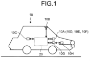
- FIG. 1 is a diagram illustrating an exemplary moving object 10 according to an arrangement.
- the moving object 10 includes an information processing apparatus 20, an output unit 10A, an external sensor 10B, an internal sensor 10C, a power control unit 10G, and a power unit 10H.
- the information processing apparatus 20 is, for example, a dedicated or general-purpose computer. According to this arrangement, it is assumed that the information processing apparatus 20 is mounted on the moving object 10 by way of example.
- the moving object 10 refers to an object that can move.
- the moving object 10 is, for example, a vehicle, a wagon, a flying object (manned air plane or unmanned airplane (such as an unmanned aerial vehicle (UAV) or a drone)), a robot, or the like.
- the moving object 10 is, for example, a moving object that travels in response to a manual driving operation or automatically travels without receiving a manual driving operation.
- the moving object 10 is a vehicle by way of example.
- the vehicle is, for example, a two-wheeled automobile, a three-wheeled automobile, a four-wheeled automobile, or the like. According to this arrangement, it is assumed that the vehicle is a four-wheeled automobile capable of an autonomous travel by way of example.
- the information processing apparatus 20 is not limited to a type mounted on the moving object 10.
- the information processing apparatus 20 may also be mounted on a stationary object.
- the stationary object refers to an object fixed on the ground.
- the stationary object is an object that is not movable or an object fixed on the ground.
- the stationary object is, for example, a guard rail, a pole, a parked vehicle, a road mark, or the like.
- the information processing apparatus 20 may also be mounted on a cloud server that executes processing via a cloud network.
- the power unit 10H is a driving device mounted on the moving object 10.
- the power unit 10H is, for example, an engine, a motor, a wheel, and the like.
- the power control unit 10G controls the power unit 10H.
- the power unit 10H is driven under control of the power control unit 10G.
- the power control unit 10G controls the power unit 10H on the basis of information obtained from the external sensor 10B and the internal sensor 10C, existence probability information derived from the processing described below, or the like in order to automatically driving the moving object 10.
- An acceleration level, a braking level, and a steering angle, or the like of the moving object 10 are controlled by controlling the power unit 10H.
- the power control unit 10G controls the vehicle so as to maintain a current traveling lane while avoiding an obstacle and maintains an interval from the front vehicle by a predetermined distance or longer.
- the output unit 10A outputs various types of information. According to this arrangement, the output unit 10A outputs a map derived from the information processing apparatus 20. The map shows an occupancy level of the obstacle. The maps will be described below in more details.
- the output unit 10A has a communication functionality for transmitting the map, a display functionality for displaying the map, a sound output functionality for outputting sound expressing the map, and the like.
- the output unit 10A includes at least one of the communication unit 10D, the display 10E, and the loudspeaker 10F. Note that, in this arrangement, it is assumed that the output unit 10A has the communication unit 10D, the display 10E, and the loudspeaker 10F by way of example.
- the communication unit 10D transmits the map to other devices.
- the communication unit 10D transmits the map to other devices via a communication line known in the art.
- the display 10E displays the map.
- the display 10E is, for example, a liquid crystal display (LCD), a projector, a light, and the like known in the art.
- the loudspeaker 10F outputs sound expressing the map.
- the external sensor 10B is a sensor for recognizing an external side in the vicinity of the moving object 10.
- the external sensor 10B may be mounted on the moving object 10 or on a location outside of the moving object 10.
- the location outside of the moving object 10 refers to, for example, another moving object, an external device, or the like.
- the vicinity of the moving object 10 refers to a region within a predetermined range from the moving object 10.
- This range is an observable range of the external sensor 10B. This range may be set in advance.
- the external sensor 10B acquires observation information of the external side.
- the observation information is information representing a result of observation for the vicinity of the installation position of the external sensor 10B.
- the observation information is information that can be used to derive position information of each of a plurality of detection points in the vicinity of the external sensor 10B (that is, the moving object 10).
- the position information of the detection point is information representing a position of the detection point in a real space.
- the position information of the detection point is information representing a distance from the external sensor 10B to the detection point and a direction of the detection point with respect to the external sensor 10B.
- These distance and direction can be expressed, for example, as position coordinates representing a relative position of the detection point with respect to the external sensor 10B, position coordinates representing an absolute position of the detection point, vectors, or the like.
- the position information is expressed in a polar coordinates system or a Cartesian coordinates system. In this arrangement, it is assumed that the position information of the detection point is expressed in the polar coordinates system by way of example.
- the detection point indicates each point individually observed by the external sensor 10B in a location outside of the moving object 10.
- the external sensor 10B irradiates light to the vicinity of the external sensor 10B and receives reflection light reflected from a reflection point. This reflection point corresponds to the detection point.
- a plurality of reflection points may be used as a single detection point. Reflection of electromagnetic waves or sound waves may also be employed.
- the external sensor 10B obtains observation information including direction of light irradiated to each of a plurality of detection points (direction of the detection point with respect to the external sensor 10B), and information on the reflection light reflected from each of a plurality of detection points.
- the information on the reflection light is, for example, time elapsing from irradiation of light to receipt of the reflection light, an intensity of the received light (or an attenuation ratio between an emitted light intensity and a received light intensity), or the like.
- the external sensor 10B derives position information of the detection point using this elapsing time and outputs it to the information processing apparatus 20.
- the position information of the detection point may be derived from the observation information using the information processing apparatus 20. In this arrangement, it is assumed that the external sensor 10B outputs position information of each detection point to the information processing apparatus 20 by way of example.
- the external sensor 10B is, for example, an image sensing device, a distance sensor (such as a millimetric wave radar or a laser sensor), a sonar sensor that detects an object using sound waves, or the like.
- the image sensing device obtains photographic image data (hereinafter, referred to as a "photographic image") through photographing.
- the image sensing device is a stereoscopic camera, a position selection camera, or the like.
- the position information may be geometrically derived using a simultaneous localization and mapping (SLAM) technique, a stereoscopic matching technique, and the like.
- SLAM simultaneous localization and mapping
- the photographic image is digital image data obtained by defining pixel values for each pixel, a depth map obtained by defining a distance from the external sensor 10B for each pixel, or the like.
- the laser sensor is, for example, a two-dimensional or three-dimensional laser imaging detection and ranging (LIDAR) sensor provided in parallel with a horizontal surface.
- LIDAR laser imaging detection and ranging
- the external sensor 10B is the image sensing device by way of example.
- the external sensor 10B is provided such that a travel direction of the moving object 10 is set as a photographing direction by way of example. For this reason, according to this arrangement, the external sensor 10B acquires position information on each detection point in a travel direction (that is, forward) of the moving object 10.
- the internal sensor 10C is a sensor for observing information on the moving object 10 of itself.
- the internal sensor 10C acquires self position information.
- the self position information includes position information of the moving object 10.
- the position information of the moving object 10 is information representing a current position of the moving object 10.
- the internal sensor 10C is, for example, an inertial measurement unit (IMU), a speed sensor, a global positioning system (GPS), or the like. Note that it is assumed that the position information of the moving object 10 is expressed in a world coordinates system.
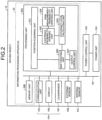
- FIG. 2 is a block diagram illustrating an exemplary configuration of the moving object 10.
- the moving object 10 includes an information processing apparatus 20, an output unit 10A, an external sensor 10B, an internal sensor 10C, a power control unit 10G, and a power unit 10H.
- the output unit 10A includes a communication unit 10D, a display 10E, and a loudspeaker 10F.
- the information processing apparatus 20, the output unit 10A, the external sensor 10B, the internal sensor 10C, and the power control unit 10G are connected to each other via a bus 10I.
- the power unit 10H is connected to the power control unit 10G.
- the information processing apparatus 20 has a memory unit 20B and a processing unit 20A. That is, the output unit 10A, the external sensor 10B, the internal sensor 10C, the power control unit 10G, the processing unit 20A, and the memory unit 20B are connected to each other via the bus 10I.
- At least one of the memory unit 20B, the output unit 10A (including the communication unit 10D, the display 10E, and the loudspeaker 10F), the external sensor 10B, the internal sensor 10C, and the power control unit 10G may be connected to the processing unit 20A in a wired or wireless manner.
- at least one of the memory unit 20B, the output unit 10A (including the communication unit 10D, the display 10E, and the loudspeaker 10F), the external sensor 10B, the internal sensor 10C, and the power control unit 10G may be connected to the processing unit 20A via a network.
- the memory unit 20B stores various types of data.
- the memory unit 20B is, for example, a random access memory (RAM), a semiconductor memory device such as a flash memory, a hard disk, an optical disk, or the like.
- the memory unit 20B may be a storage device provided outside the information processing apparatus 20.
- the memory unit 20B may be a storage medium.
- the storage medium may be a medium that stores or temporarily stores a program or various types of information downloaded via a local area network (LAN), the Internet, or the like.
- the memory unit 20B may include a plurality of storage media.
- the processing unit 20A includes a position acquiring unit 20C, a map creating unit 20D, an existence probability deriving unit 20E, a non-measurement probability deriving unit 20F, an occupancy level calculating unit 20G, and an output control unit 20H.
- the position acquiring unit 20C, the map creating unit 20D, the existence probability deriving unit 20E, the non-measurement probability deriving unit 20F, the occupancy level calculating unit 20G, and the output control unit 20H are implemented, for example, by a single or a plurality of processors.
- each of the aforementioned units may be implemented by allowing a processor such as a central processing unit (CPU) to execute a program, that is, software.
- CPU central processing unit
- Each of the aforementioned units may be implemented by a processor such as a dedicated integrated circuit (IC), that is, hardware.
- IC integrated circuit
- Each of the aforementioned units may also be implemented by both software and hardware.
- each processor may implement one of the units or may implement two or more units.
- processor refers to, for example, a CPU, a graphical processing unit (GPU), an application specific integrated circuit (ASIC), a programmable logic device (such as a simple programmable logic device (SPLD)), a complex programmable logic device (CPLD), or a field programmable gate array (FPGA) circuit.
- GPU graphical processing unit
- ASIC application specific integrated circuit
- SPLD simple programmable logic device
- CPLD complex programmable logic device
- FPGA field programmable gate array
- the processor implements each of the aforementioned units by reading and executing a program stored in the memory unit 20B.
- the program may be directly embedded in the circuit of the processor instead of storing it in the memory unit 20B.
- the processor implements each of the aforementioned units by reading and executing the program embedded in the circuit.
- the position acquiring unit 20C acquires position-related information.
- the position-related information includes at least position information of the detection point. According to this arrangement, the position-related information includes position information of the detection point and the self position information.
- the processing unit 20A derives the map by performing the following processing using the position-related information.
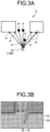
- FIG. 3A is an explanatory diagram illustrating an example of deriving the map.
- the external sensor 10B mounted on the moving object 10 acquires position information on each of a plurality of detection points P in a real space S.
- the position acquiring unit 20C acquires the position information on each of a plurality of detection points P detected by the external sensor 10B.
- the position acquiring unit 20C acquires a density of the detection point P detectable by the external sensor 10B, that is, position information for the detection points P whose number corresponds to a resolution of the external sensor 10B.
- the position information of the detection point P is expressed, for example, in the polar coordinates system.
- the external sensor 10B may acquire three-dimensional information of the detection point expressed in the Cartesian coordinates system.
- the position acquiring unit 20C may convert the Cartesian coordinates into the polar coordinates.
- the position acquiring unit 20C acquires position information expressed in the polar coordinates system as the position information of the detection point P. That is, the position information of the detection point P is expressed using a distance "r" (also referred to as a "radius vector") and an angle " ⁇ " (also referred to as a "deflection angle”) in the polar coordinates space.
- the angle ⁇ indicates a direction on the x-y plane parallel to an estimated ground surface during a travel of the moving object 10 (a plane orthogonal to the vertical direction) by setting the position of the moving object 10 as an origin.
- a position of the moving object 10 and a current position of the moving object 10 refer to a current position of the moving object 10 mounted on the information processing apparatus 20. That is, the position information on the moving object 10 is information representing a position of the moving object 10 (current position).
- a direction of the angle ⁇ obtained by setting the current position of the moving object 10 as an origin on the x-y plane of the polar coordinates space may be referred to as an "angular direction.”
- the x-y plane in the polar coordinates space is a plane orthogonal to the radial direction of the polar coordinates space.
- the angular direction ( ⁇ direction) refers to a direction indicating the angle ⁇ from the x-axis or the y-axis out of a pair of deflection angles ⁇ and ⁇ perpendicular to the radial direction of the polar coordinates space.
- the radial direction in the polar coordinates space will be referred to as a "distance direction.”
- the radial direction refers to a direction (r-direction) indicating a distance (distance r) to the detection point P by setting the current position of the moving object 10 as an origin and also a direction along the radial axis.
- the position information of the detection point P is expressed in the polar coordinates system including the angle ⁇ in practice.
- the angle ⁇ is an angle with respect to the orthogonal line (z-axis) to the x-y plane parallel to the estimated ground surface during a travel of the moving object 10. In this arrangement, the angle ⁇ will not be considered, so that it will not be described further.
- the position acquiring unit 20C may acquire the position information of the detection point P from an external device.
- the position acquiring unit 20C may acquire the position information of the detection point P from the external device via the communication unit 10D.
- the self position information includes the position information of the moving object 10.
- the position acquiring unit 20C acquires the self position information from the internal sensor 10C. Note that it is assumed that the position information of the moving object 10 is expressed, for example, in the world coordinates system.
- the position acquiring unit 20C outputs position-related information including position information of a plurality of detection points P and the self position information to the map creating unit 20D.
- the map creating unit 20D creates a map.
- FIG. 3B is a schematic diagram illustrating an example of the displayed map M.
- the map M is a map that defines an occupancy level of the target. According to this arrangement, the map M includes a plurality of domains G, and the occupancy level of the target calculated by the occupancy level calculating unit 20G is defined for each domain G.
- the target is a specific target object having the occupancy level.
- the target may be appropriately set depending on a type of the target moving object 10 mounted with the information processing apparatus 20.
- the target is, for example, an obstacle.
- the obstacle is an object that obstructs a travel of the moving object 10 mounted with the information processing apparatus 20.
- the obstacle is, for example, a three-dimensional object such as another vehicle, a building, and a wall.
- the occupancy level indicates an occupancy level of the target defined in the map M.
- the occupancy level is an occupancy level of the target defined for each domain G in the map M.
- the occupancy level of the target is a ratio of the domain G occupied by the target.
- the occupancy level of the target may be an existence probability of the target existing in the domain G.
- the occupancy level is expressed, for example, as a value having a range equal to or greater than 0.0 and equal to or smaller than 1.0.
- the domain G is each of a plurality of regions obtained by dividing the map M.
- the shape of the domain G is not particularly limited.
- the domain G has a rectangular shape.
- the shape of the domain G is not limited to a square.
- the domain G may have an oblong shape or the like, or a fan shape divided by concentric circles having the moving object 10 at the center and radial lines.
- the map creating unit 20D creates the map M on the basis of the self position information of the moving object 10, domain information representing a size and position of the domain G, position information of the detection point P acquired from the position acquiring unit 20C, and an occupancy level distribution D3 calculated by the occupancy level calculating unit 20G. As a result, the map creating unit 20D acquires the map M. Specifically, the map creating unit 20D creates the map M by setting the occupancy levels for the domains G divided radially from the current position of the moving object 10 toward the detection point P acquired by the position acquiring unit 20C.
- the occupancy level calculating unit 20G will be described below in more details.
- the existence probability deriving unit 20E derives accuracy information of the external sensor 10B, position information acquired by the position acquiring unit 20C, and an existence probability distribution D1 of the target at each position and outputs them to the occupancy level calculating unit 20G.
- the existence probability deriving unit 20E derives the existence probability distribution D1 that changes depending on the measurement accuracy. For example, the existence probability deriving unit 20E derives the existence probability distribution D1 such that the spread becomes larger as the measurement accuracy of the external sensor 10B decreases, and the distribution becomes narrower (steep distribution) as the measurement accuracy increases.
- the accuracy information of the external sensor 10B is information from which the existence probability at each position of the target can be derived when a specific output of the external sensor 10B is obtained.
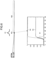
- FIG. 4 illustrates an exemplary existence probability distribution D1.
- the existence probability deriving unit 20E derives the existence probability distribution D1 expressed as a normal distribution having an average value at a position indicated by the position information acquired by the position acquiring unit 20C and a variance proportional to the accuracy information (distance).
- This normal distribution is, for example, a one-dimensional normal distribution expressing a probability distribution for the distance along a direction from the position of the external sensor 10B to the target.
- the existence probability distribution D1 is derived for each detected target.
- FIG. 4 illustrates three exemplary graphs 501, 502, and 503 including the existence probability distributions D1 corresponding to three detected targets. In FIG. 4 , the distance becomes farther, and the variance of the existence probability distribution D1 increases in the order of the graphs 501, 502, and 503.
- the existence probability deriving unit 20E derives the existence probability distribution D1 expressed as a normal distribution having an average value at the position indicated by the position information acquired by the position acquiring unit 20C and a variance inversely proportional to the accuracy information (reflection intensity).
- the accuracy information of the external sensor 10B is not limited to the information derived from the distance and the reflection intensity, but may include any type of information as long as it represents accuracy of the external sensor 10B when the position of the target is detected.
- the existence probability distribution D1 is not limited to the normal distribution.
- the existence probability distribution D1 may be a nonparametric distribution created from a plurality of sensor values experimentally measured in advance using machine learning and position information of a real target.
- the existence probability distribution D1 at each value of the parameters (such as the distance and the reflection intensity) relating to accuracy of the external sensor 10B may be calculated in advance and stored in a memory, and the stored value may be read.
- any method of calculating the existence probability distribution known in the art may also be employed.
- the non-measurement probability deriving unit 20F derives a non-measurement probability distribution.
- the non-measurement probability distribution is a probability distribution that changes depending on the position indicated by the position information and the measurement accuracy of the external sensor 10B to express a probability that a target is not measured by the external sensor 10B.
- the non-measurement probability deriving unit 20F calculates a non-measurement probability distribution D2 at each position from the existence probability distribution D1 obtained by the existence probability deriving unit 20E and outputs it to the occupancy level calculating unit 20G.
- the non-measurement probability distribution D2 may be calculated by accumulating the existence probability distribution D1 from the position (sensor position) of the external sensor 10B toward the target.
- a non-measurement situation occurs when the target exists in a certain position, and a rear side of the target position is not measured due to blocking as seen from the sensor position. For this reason, the non-measurement probability may be substituted with a blocking probability. That is, accumulation of the existence probability distribution D1 from the sensor position to the target position corresponds to the non-measurement probability at that position.
- the existence probability distribution D1 is defined as a normal distribution function and the non-measurement probability deriving unit 20F sets a non-measurement probability distribution D2 in an analytic manner by integrating the existence probability distribution D1.
- FIG. 4 also illustrates an example of the non-measurement probability distribution D2.
- a change in the non-measurement probability distribution D2 becomes gentle, and a boundary between the measurement region and the non-measurement region becomes unclear.
- the non-measurement probability deriving unit 20F may approximately derive the non-measurement probability distribution D2 using numerical integration.
- the occupancy level calculating unit 20G derives the occupancy level (occupancy level distribution) indicating a level of occupancy, by the target, of each of a plurality of regions.
- FIGS. 5A and 5B are explanatory diagrams illustrating an exemplary occupancy level distribution used when existence of the target is unknown and a fixed median value (0.5) is set as the occupancy level.
- FIG. 5A illustrates an example of the occupancy level when the position of the target is detected with high accuracy (0.9).
- FIG. 5B illustrates an example of the occupancy level when the position of the target is detected with low accuracy (0.4).
- existence of the target is unknown and the fixed median value is set as the occupancy level, it is likely that the median value increases from the occupancy level at the position of the target as illustrated in FIG. 5B . That is, it may be difficult to set an appropriate occupancy level in some cases.
- the occupancy level calculating unit 20G calculates the occupancy level distribution on the basis of the position information and measurement accuracy of the external sensor 10B.
- the occupancy level distribution is calculated as a distribution based on the non-measurement probability distribution.
- the occupancy level calculating unit 20G calculates the occupancy level distribution D3 from the existence probability distribution D1 acquired by the existence probability deriving unit 20E and the non-measurement probability distribution D2 acquired by the non-measurement probability deriving unit 20F and outputs it to the map creating unit 20D.
- the occupancy level calculating unit 20G calculates the occupancy level distribution D3 by obtaining a weighted sum of the existence probability distribution D1 and the non-measurement probability distribution D2.
- FIG. 4 illustrates the occupancy level distribution D3 calculated by applying a weight of 0.5 to the existence probability distribution D1 and the non-measurement probability distribution D2 and adding them.
- the weight is not limited to 0.5, but any value may be employed. Since the measurement accuracy of the external sensor 10B is high at the distance corresponding to the graph 501, nearly the same occupancy level as that of FIG. 5A is obtained.
- the measurement accuracy of the external sensor 10B is low, and the peak of the existence probability distribution D1 is lower than 0.5.
- the occupancy level distribution D3 is appropriately obtained.
- a peak position of the occupancy level distribution D3 is slightly deviated backward relative to the peak of the existence probability distribution D1. This is because the rear side of the target is not measured, and a possibility of existence of the target remains although the front side of the target is measured, and it is apparent that no target exists. That is, there is no theoretical problem if the existence probability of the rear side becomes high.
- the measurement accuracy is significantly low. Therefore, the position of the target is unknown, but at least a fact that the rear side of the target is not measured is correctly reflected in the occupancy level distribution D3.
- the occupancy level calculating unit 20G may calculate the occupancy level distribution D3 only from the non-measurement probability distribution D2, without using the existence probability distribution D1. This is because, in the control of the moving object, it is important to know a region allowed to travel, that is, a region where no target exists through measurement, and it is not indispensable to distinguish between the non-measurement region and the region where an object exists.
- the occupancy level calculating unit 20G does not use the existence probability distribution D1 in calculation of the occupancy level distribution D3.
- the occupancy level calculating unit 20G calculates the occupancy level distribution D3 by multiplying the non-measurement probability distribution D2 by a constant (for example, 0.5 times).
- the existence probability deriving unit 20E may calculate the existence probability even when it is measured that "no target exists.” For example, the existence probability deriving unit 20E derives the existence probability distribution D1 using a position where it is measured that no target exists instead of a position where it is measured that a target exists. The existence probability deriving unit 20E may derive the existence probability distribution D1 using a nonparametric distribution measured in advance under a situation that no target exists.
- the non-measurement probability deriving unit 20F may also derive the non-measurement probability distribution D2 by integrating the existence probability distribution D1 when it is measured that "no target exists.”
- FIG. 6 is a diagram illustrating examples of the existence probability distribution D1, the non-measurement probability distribution D2, and the occupancy level distribution D3 when no target exists.
- FIG. 6 illustrates an example when it is measured that no target exists in the same position 801 as that corresponding to the graph 502 of FIG. 4 .
- the region 802 indicates a region where it is unclear whether or not a target exists.
- the non-measurement probability deriving unit 20F may directly calculate the non-measurement probability distribution D2 from the accuracy information of the external sensor 10B.
- the non-measurement probability distribution at each value of the parameters relating to the accuracy of the external sensor 10B may be calculated in advance, may be stored in a memory, and may be read. In this configuration, the existence probability deriving unit 20E may not be provided.
- the position information of each point observed by the external sensor 10B may include other points in addition to the point on the target.
- the points other than the point on the target include a road surface that does not hinder a travel of the vehicle, or the like.
- Whether or not a target exists may be determined, for example, in the following way.
- the output control unit 20H controls the output of the map M created by the map creating unit 20D.
- the output control unit 20H outputs the map M to the power control unit 10G that controls the power unit 10H of the moving object 10.
- the output control unit 20H displays the map M on the display 10E. According to this arrangement, the output control unit 20H displays a presentation screen including the map M on the display 10E.
- FIG. 3B is a schematic diagram illustrating an exemplary presentation screen.
- the presentation screen includes a map M created by the map creating unit 20D. For this reason, a user easily recognizes the occupancy ratio of the target object by checking the presentation screen.
- the output control unit 20H may control the display 10E or the loudspeaker 10F such that sound or light representing the occupancy level for each domain G presented on the map M is output.
- the output control unit 20H may transmit the map M to an external device via the communication unit 10D. For example, when there is a domain G having a high occupancy level in the travel direction of the moving object 10, the display 10E may be flickered, or an alert sound may be output from the loudspeaker 10F.
- the output control unit 20H may output the map M to the power control unit 10G.
- the power control unit 10G controls the power unit 10H depending on the map M received from the output control unit 20H.
- the power control unit 10G may generate a power control signal for controlling the power unit 10H depending on the map M to control the power unit 10H.
- the power control signal is a control signal for controlling a driving unit that drives a travel of the moving object 10 in the power unit 10H.
- the power control unit 10G controls steering of the moving object 10, an engine, or the like such that the moving object 10 travels in the region of the real space S corresponding to the domain G, displayed on the map M, representing an occupancy ratio showing a region allowed to travel.
- FIG. 7 is a flowchart illustrating an exemplary information processing sequence executed by the information processing apparatus 20 according to this arrangement.
- the position acquiring unit 20C acquires the position-related information (step S101).
- the position-related information includes position information of the detection point.
- the following processes are executed for each detection point (target) for which the position information has been acquired.
- the existence probability deriving unit 20E derives the existence probability distribution D1 for an unprocessed detection point from the accuracy information of the external sensor 10B and the position information of the corresponding detection point (step S102).
- the non-measurement probability deriving unit 20F derives the non-measurement probability distribution D2 by integrating the existence probability distribution D1 (step S103).
- the occupancy level calculating unit 20G calculates the occupancy level distribution D3 from the existence probability distribution D1 and the non-measurement probability distribution D2 (step S104).
- the map creating unit 20D reflects the calculated occupancy level distribution D3 on the map M (step S105).
- the processing unit 20A determines whether or not all of the detection points have been processed (step S106). If all of the detection points have not been processed (step S106: No), the process returns to step S102 to repeat the processing for the next detection point. If all of the detection points have been processed (step S106: Yes), the output control unit 20H outputs the map M (step S107) and terminates the information processing.
- the information processing apparatus 20 includes the existence probability deriving unit 20E, the non-measurement probability deriving unit 20F, and the occupancy level calculating unit 20G.
- the existence probability deriving unit 20E acquires the existence probability distribution D1 of the target at each position from the accuracy information of the external sensor 10B and the position information acquired by the position acquiring unit 20C.
- the non-measurement probability deriving unit 20F calculates the non-measurement probability distribution D2 representing a probability that a target is not measured by the external sensor 10B at each position from the existence probability distribution D1.
- the occupancy level calculating unit 20G calculates the occupancy level distribution D3 from the existence probability distribution D1 and the non-measurement probability distribution D2.
- the information processing apparatus 20 calculates the occupancy level of the unmeasured position backside of the target using the non-measurement probability distribution D2. For this reason, it is possible to appropriately calculate the occupancy level distribution D3 even when the accuracy of the external sensor 10B is low, and the peak of the existence probability distribution D1 is lower than 0.5.
- the information processing apparatus 20 can calculate the non-measurement probability distribution D2 even when no target exists. For this reason, it is possible to calculate the occupancy level distribution D3 from the information obtained by measuring a fact that "no target exists" as well as information obtained from the external sensor 10B by measuring the target.
- FIG. 8 is an exemplary hardware block diagram illustrating the information processing apparatus 20 according to this arrangement.
- the information processing apparatus 20 includes: a control unit such as a CPU 86; a memory unit such as a read-only memory (ROM) 88, a RAM 90, or a hard disk drive (HDD) 92; an I/F unit 82 as an interface with various devices; an output unit 80 that outputs various types of information such as the output information; an input unit 94 that receives a user's manipulation; and a bus 96 that connects each unit.
- a control unit such as a CPU 86
- a memory unit such as a read-only memory (ROM) 88, a RAM 90, or a hard disk drive (HDD) 92
- an I/F unit 82 as an interface with various devices
- an output unit 80 that outputs various types of information such as the output information
- an input unit 94 that receives a user's manipulation
- a bus 96 that connects each unit.
- each unit is implemented on the computer by allowing the CPU 86 to read the program from the ROM 88 and execute it on the RAM 90.
- the program for executing each of the processes executed by the information processing apparatus 20 according to the aforementioned arrangement may be stored in the HDD 92.
- the program for executing each of the aforementioned processes executed by the information processing apparatus 20 according to the aforementioned arrangement may be embedded in the ROM 88 in advance.
- the program for executing the aforementioned processes executed by the information processing apparatus 20 according to the aforementioned arrangement may be stored in a computer readable storage medium such as a CD-ROM, a CD-R, a memory card, a digital versatile disk (DVD), and a flexible disk (FD) in an installable or executable format file and may be provided as a computer program product.
- the program for executing the aforementioned processes executed by the information processing apparatus 20 according to the aforementioned arrangement may be stored in a computer connected via a network such as the Internet and may be downloaded via the network.
- the program for executing the aforementioned processes executed by the information processing apparatus 20 according to the aforementioned arrangement may be provided or distributed via a network such as the Internet.
Landscapes
- Engineering & Computer Science (AREA)
- Physics & Mathematics (AREA)
- General Physics & Mathematics (AREA)
- Theoretical Computer Science (AREA)
- Remote Sensing (AREA)
- Radar, Positioning & Navigation (AREA)
- Computer Networks & Wireless Communication (AREA)
- Multimedia (AREA)
- Computer Vision & Pattern Recognition (AREA)
- Artificial Intelligence (AREA)
- Evolutionary Computation (AREA)
- Bioinformatics & Computational Biology (AREA)
- Probability & Statistics with Applications (AREA)
- Evolutionary Biology (AREA)
- Bioinformatics & Cheminformatics (AREA)
- Life Sciences & Earth Sciences (AREA)
- Chemical & Material Sciences (AREA)
- Analytical Chemistry (AREA)
- Electromagnetism (AREA)
- Computing Systems (AREA)
- Data Mining & Analysis (AREA)
- Databases & Information Systems (AREA)
- General Health & Medical Sciences (AREA)
- Health & Medical Sciences (AREA)
- Medical Informatics (AREA)
- Software Systems (AREA)
- General Engineering & Computer Science (AREA)
- Traffic Control Systems (AREA)
Claims (8)
- Informationsverarbeitungsapparat (20), umfassend:eine Positionserfassungseinheit (20C), die konfiguriert ist, eine Positionsinformation zu erfassen, die eine Position darstellt, an der ein Ziel existiert oder kein Ziel existiert, wobei die Position durch einen Sensor (10B) gemessen wird;eine Belegungsebenenberechnungseinheit (20G), die konfiguriert ist, eine Belegungsebenenverteilung (D3) zu berechnen, die eine Ebene der Belegung durch das Ziel von jedem einer Vielzahl von Bereichen darstellt, die entlang einer Richtung von der Position des Sensors (10B) zu der Position existieren, die durch die Positionsinformation angegeben wird, basierend auf der Positionsinformation und der Messgenauigkeit des Sensors (10B), wobei die Belegungsebenenverteilung (D3) auf einer Nichtmessungswahrscheinlichkeitsverteilung (D2) basiert, die eine Wahrscheinlichkeit repräsentiert, dass keine Messung durch den Sensor (10B, 10C) durchgeführt wird;eine Existenzwahrscheinlichkeitsableitungseinheit (20E), die konfiguriert ist, eine Existenzwahrscheinlichkeitsverteilung (D1) abzuleiten, die eine Existenzwahrscheinlichkeit des Ziels darstellt, wobei sich die Existenzwahrscheinlichkeitsverteilung (D1) abhängig von der Messgenauigkeit ändert, basierend auf der Positionsinformation und der Messgenauigkeit; undeine Nichtmessungswahrscheinlichkeitsableitungseinheit (20F), die konfiguriert ist, die Nichtmessungswahrscheinlichkeitsverteilung (D2) durch Integrieren der Existenzwahrscheinlichkeit in einer Richtung von der Position des Sensors (10B) zu der durch die Positionsinformation angezeigten Position abzuleiten, wobei die Existenzwahrscheinlichkeitsverteilung (D1) als eine Normalverteilungsfunktion definiert ist,wobei die Belegungsebenenberechnungseinheit (20G) konfiguriert ist, die Belegungsebenenverteilung (D3) basierend auf der Existenzwahrscheinlichkeitsverteilung (D1) und der Nichtmessungswahrscheinlichkeitsverteilung (D2) zu berechnen, undwobei die Belegungsebenenberechnungseinheit (20G) konfiguriert ist, die Belegungsebenenverteilung (D3) basierend auf einer gewichteten Summe der Existenzwahrscheinlichkeitsverteilung (D1) und der Nichtmessungswahrscheinlichkeitsverteilung (D2) zu berechnen.
- Informationsverarbeitungsapparat (20) gemäß Anspruch 1, wobei
die Existenzwahrscheinlichkeitsableitungseinheit (20E) konfiguriert ist, die Existenzwahrscheinlichkeitsverteilung (D1) als eine Normalverteilung mit einer größeren Varianz abzuleiten, wenn die Messgenauigkeit abnimmt. - Informationsverarbeitungsapparat (20) gemäß Anspruch 1 oder 2,
ferner umfassend eine Kartenerstellungseinheit (20D), die konfiguriert ist, eine Karte zu erstellen, in der eine Belegungsebene basierend auf der Belegungsebenenverteilung (D3) in einer Vielzahl von Bereichen festgelegt ist, die durch Teilen eines Bereichs, der einen Messbereich des Sensors (10B) enthält, erhalten werden. - Informationsverarbeitungsapparat (20) gemäß einem der Ansprüche 1 bis 3, wobei
die Messgenauigkeit von einem Abstand zwischen der Position des Sensors (10B) und der durch die Positionsinformation angegebenen Position abgeleitet wird. - Informationsverarbeitungsapparat (20) gemäß einem der Ansprüche 1 bis 3, wobeider Sensor (10B) konfiguriert ist, das Ziel durch Empfangen von am Ziel reflektiertem Licht zu messen, unddie Messgenauigkeit von einer Intensität des vom Sensor (10B) empfangenen Lichts abgeleitet wird.
- Bewegendes Objekt (10), umfassend:einen Sensor (10B);der Informationsverarbeitungsapparat (20) gemäß einem der Ansprüche 1 bis 5; undeine Leistungssteuereinheit (10G), die konfiguriert ist, eine Leistung des sich bewegenden Objekts basierend auf der Belegungsebenenverteilung (D3) zu steuern.
- Computerimplementiertes Informationsverarbeitungsverfahren, umfassend:Erfassen einer Positionsinformation, die eine Position darstellt, an der ein Ziel vorhanden ist oder kein Ziel vorhanden ist, wobei die Position durch einen Sensor (10B) (S101) gemessen wird;Berechnen einer Belegungsebenenverteilung (D3), die eine Ebene der Belegung durch das Ziel von jeder einer Vielzahl von Regionen darstellt, die entlang einer Richtung von der Position des Sensors (10B) zu der Position vorhanden sind, die durch die Positionsinformation angegeben wird, basierend auf der Positionsinformation und der Messgenauigkeit des Sensors (10B) (S104), wobei die Belegungsebenenverteilung (D3) auf der Nichtmessungswahrscheinlichkeitsverteilung (D2) basiert, die eine Wahrscheinlichkeit darstellt, dass keine Messung durch den Sensor durchgeführt wird;Ableiten einer Existenzwahrscheinlichkeitsverteilung (D1), die eine Existenzwahrscheinlichkeit des Ziels darstellt, wobei sich die Existenzwahrscheinlichkeitsverteilung (D1) in Abhängigkeit von der Messgenauigkeit ändert, basierend auf der Positionsinformation und der Messgenauigkeit (S102); undAbleiten der Nichtmessungswahrscheinlichkeitsverteilung (D2) durch Integrieren der Existenzwahrscheinlichkeit in einer Richtung von der Position des Sensors (10B) zu der durch die Positionsinformation (S103) angegebenen Position, wobei die Existenzwahrscheinlichkeitsverteilung (D1) als eine Normalisierungsfunktion definiert ist,wobei die Belegungsebenenverteilung (D3) basierend auf der Existenzwahrscheinlichkeitsverteilung (D1) und der Nichtmessungswahrscheinlichkeitsverteilung (D2) berechnet wird, undwobei die Belegungsgradverteilung (D3) basierend auf einer gewichteten Summe der Existenzwahrscheinlichkeitsverteilung (D1) und der Nichtmessungswahrscheinlichkeitsverteilung (D2) berechnet wird.
- Computerlesbares Medium, umfassend Anweisungen, die, wenn sie von einem Computer (86) ausgeführt werden, den Computer dazu veranlassen, das Verfahren gemäß Anspruch 7 auszuführen.
Applications Claiming Priority (1)
| Application Number | Priority Date | Filing Date | Title |
|---|---|---|---|
| JP2017153254A JP6808590B2 (ja) | 2017-08-08 | 2017-08-08 | 情報処理装置、情報処理方法、プログラムおよび移動体 |
Publications (2)
| Publication Number | Publication Date |
|---|---|
| EP3441906A1 EP3441906A1 (de) | 2019-02-13 |
| EP3441906B1 true EP3441906B1 (de) | 2025-02-19 |
Family
ID=61557182
Family Applications (1)
| Application Number | Title | Priority Date | Filing Date |
|---|---|---|---|
| EP18159701.4A Active EP3441906B1 (de) | 2017-08-08 | 2018-03-02 | Informationsverarbeitungsvorrichtung, bewegtes objekt, informationsverarbeitungsverfahren und computerlesbares medium |
Country Status (3)
| Country | Link |
|---|---|
| US (1) | US10885353B2 (de) |
| EP (1) | EP3441906B1 (de) |
| JP (1) | JP6808590B2 (de) |
Families Citing this family (9)
| Publication number | Priority date | Publication date | Assignee | Title |
|---|---|---|---|---|
| JP7182895B2 (ja) | 2018-04-13 | 2022-12-05 | 株式会社東芝 | 情報処理装置、プログラム、および情報処理方法 |
| FR3097972B1 (fr) * | 2019-06-28 | 2021-12-10 | Aptiv Tech Ltd | Procédé et système pour cartographier un environnement physique au moyen d’une grille d’occupation |
| CN110516702B (zh) * | 2019-07-18 | 2022-07-05 | 电子科技大学 | 一种基于流数据的离散路径规划方法 |
| EP3882813B1 (de) | 2020-03-20 | 2025-05-07 | Aptiv Technologies AG | Verfahren zur erzeugung eines dynamischen belegungsrasters |
| EP3888988B1 (de) | 2020-03-30 | 2024-09-04 | Aptiv Technologies AG | Verfahren und system zur bestimmung eines nutzbaren abstands vor einem fahrzeug |
| CN111487629A (zh) * | 2020-04-02 | 2020-08-04 | 新石器慧通(北京)科技有限公司 | 传感器安置机台及无人车 |
| EP3905106A1 (de) | 2020-04-27 | 2021-11-03 | Aptiv Technologies Limited | Verfahren zur bestimmung einer befahrbaren fläche |
| EP3905105A1 (de) * | 2020-04-27 | 2021-11-03 | Aptiv Technologies Limited | Verfahren zur bestimmung eines kollisionsfreien raumes |
| CN111856157A (zh) * | 2020-08-27 | 2020-10-30 | 上海眼控科技股份有限公司 | 闪电位置测量方法、装置、计算机设备和存储介质 |
Family Cites Families (14)
| Publication number | Priority date | Publication date | Assignee | Title |
|---|---|---|---|---|
| JP2007333486A (ja) | 2006-06-13 | 2007-12-27 | Denso Corp | 車両用障害物検知装置 |
| JP2011123551A (ja) * | 2009-12-08 | 2011-06-23 | Toyota Central R&D Labs Inc | 死角領域推定装置及びプログラム |
| JP5206752B2 (ja) * | 2010-08-30 | 2013-06-12 | 株式会社デンソー | 走行環境認識装置 |
| JP5475138B2 (ja) * | 2010-09-08 | 2014-04-16 | トヨタ自動車株式会社 | 移動物予測装置、仮想可動物予測装置、プログラム、移動物予測方法、及び仮想可動物予測方法 |
| JP5712900B2 (ja) * | 2011-11-08 | 2015-05-07 | トヨタ自動車株式会社 | 周辺物体検出装置 |
| JP5494845B1 (ja) * | 2013-01-17 | 2014-05-21 | 株式会社デンソーアイティーラボラトリ | 情報提供システム |
| DE102016101650A1 (de) * | 2015-01-29 | 2016-08-04 | Affectomatics Ltd. | Korrektur von bias in messwerten der affektiven reaktion |
| CN108028023B (zh) * | 2015-09-30 | 2021-10-26 | 索尼公司 | 信息处理装置、信息处理方法和计算机可读存储介质 |
| JP6559535B2 (ja) * | 2015-10-22 | 2019-08-14 | 株式会社東芝 | 障害物マップ生成装置、その方法、及び、そのプログラム |
| US11222438B2 (en) | 2016-05-27 | 2022-01-11 | Kabushiki Kaisha Toshiba | Information processing apparatus, vehicle, and information processing method for presence probability of object |
| US11132611B2 (en) | 2016-05-27 | 2021-09-28 | Kabushiki Kaisha Toshiba | Information processing apparatus and information processing method for determining presence probability of object |
| US11204610B2 (en) | 2016-05-30 | 2021-12-21 | Kabushiki Kaisha Toshiba | Information processing apparatus, vehicle, and information processing method using correlation between attributes |
| EP3252658B1 (de) | 2016-05-30 | 2021-08-11 | Kabushiki Kaisha Toshiba | Informationsverarbeitungsvorrichtung und informationsverarbeitungsverfahren |
| JP6804991B2 (ja) | 2017-01-05 | 2020-12-23 | 株式会社東芝 | 情報処理装置、情報処理方法、および情報処理プログラム |
-
2017
- 2017-08-08 JP JP2017153254A patent/JP6808590B2/ja active Active
-
2018
- 2018-03-02 EP EP18159701.4A patent/EP3441906B1/de active Active
- 2018-03-05 US US15/911,310 patent/US10885353B2/en active Active
Also Published As
| Publication number | Publication date |
|---|---|
| US10885353B2 (en) | 2021-01-05 |
| JP2019032700A (ja) | 2019-02-28 |
| JP6808590B2 (ja) | 2021-01-06 |
| US20190050649A1 (en) | 2019-02-14 |
| EP3441906A1 (de) | 2019-02-13 |
Similar Documents
| Publication | Publication Date | Title |
|---|---|---|
| US10885353B2 (en) | Information processing apparatus, moving object, information processing method, and computer program product | |
| JP7297017B2 (ja) | オンボードセンサの外部パラメータを較正する方法及び装置、並びに関連する車両 | |
| US10909411B2 (en) | Information processing apparatus, information processing method, and computer program product | |
| EP3812793B1 (de) | Informationsverarbeitungsverfahren, system und vorrichtung sowie computerspeichermedium | |
| US11132611B2 (en) | Information processing apparatus and information processing method for determining presence probability of object | |
| CN110959143B (zh) | 信息处理装置、信息处理方法、程序和移动体 | |
| US11250288B2 (en) | Information processing apparatus and information processing method using correlation between attributes | |
| US11921239B2 (en) | Methods and systems for calibration of multiple lidar devices with non-overlapping fields of view | |
| JP6029446B2 (ja) | 自律飛行ロボット | |
| US11222438B2 (en) | Information processing apparatus, vehicle, and information processing method for presence probability of object | |
| EP3553752A1 (de) | Informationsverarbeitungsvorrichtung, informationsverarbeitungsverfahren und computerlesbares medium zum generieren einer hinderniskarte | |
| US20200103920A1 (en) | Stationary camera localization | |
| US11204610B2 (en) | Information processing apparatus, vehicle, and information processing method using correlation between attributes | |
| KR102759290B1 (ko) | Lidar 센서가 장착된 자동차의 도로 감지 방법 | |
| US11105924B2 (en) | Object localization using machine learning | |
| JP2017016359A (ja) | 自律移動ロボット | |
| US11087145B2 (en) | Gradient estimation device, gradient estimation method, computer program product, and controlling system | |
| WO2018221455A1 (ja) | 更新装置、制御方法、プログラム及び記憶媒体 | |
| JP2016173709A (ja) | 自律移動ロボット | |
| US12535322B2 (en) | System and methods of vehicle pose estimation | |
| JP6813436B2 (ja) | 情報処理装置、移動体、情報処理方法、およびプログラム | |
| WO2024004722A1 (ja) | 電子機器、制御方法および制御プログラム | |
| WO2018221456A1 (ja) | 経路探索装置、制御方法、プログラム及び記憶媒体 | |
| EP4586229A1 (de) | Systeme und verfahren zur flugzeuglandeführung während gnss-verweigerter umgebung | |
| HK40050604B (zh) | 使用被动和主动测量生成场景的三维地图 |
Legal Events
| Date | Code | Title | Description |
|---|---|---|---|
| PUAI | Public reference made under article 153(3) epc to a published international application that has entered the european phase |
Free format text: ORIGINAL CODE: 0009012 |
|
| STAA | Information on the status of an ep patent application or granted ep patent |
Free format text: STATUS: REQUEST FOR EXAMINATION WAS MADE |
|
| 17P | Request for examination filed |
Effective date: 20180302 |
|
| AK | Designated contracting states |
Kind code of ref document: A1 Designated state(s): AL AT BE BG CH CY CZ DE DK EE ES FI FR GB GR HR HU IE IS IT LI LT LU LV MC MK MT NL NO PL PT RO RS SE SI SK SM TR |
|
| AX | Request for extension of the european patent |
Extension state: BA ME |
|
| STAA | Information on the status of an ep patent application or granted ep patent |
Free format text: STATUS: EXAMINATION IS IN PROGRESS |
|
| 17Q | First examination report despatched |
Effective date: 20210729 |
|
| REG | Reference to a national code |
Ref country code: DE Ref legal event code: R079 Free format text: PREVIOUS MAIN CLASS: G06K0009000000 Ipc: G08G0001160000 Ref document number: 602018079258 Country of ref document: DE |
|
| GRAP | Despatch of communication of intention to grant a patent |
Free format text: ORIGINAL CODE: EPIDOSNIGR1 |
|
| STAA | Information on the status of an ep patent application or granted ep patent |
Free format text: STATUS: GRANT OF PATENT IS INTENDED |
|
| RIC1 | Information provided on ipc code assigned before grant |
Ipc: G01S 13/86 20060101ALN20240909BHEP Ipc: G01S 15/931 20200101ALN20240909BHEP Ipc: G01S 7/40 20060101ALN20240909BHEP Ipc: G01S 13/931 20200101ALN20240909BHEP Ipc: G06V 10/20 20220101ALI20240909BHEP Ipc: G06V 10/764 20220101ALI20240909BHEP Ipc: G06V 20/52 20220101ALI20240909BHEP Ipc: G06V 20/58 20220101ALI20240909BHEP Ipc: G01S 17/931 20200101ALI20240909BHEP Ipc: G01S 7/52 20060101ALI20240909BHEP Ipc: G01S 7/497 20060101ALI20240909BHEP Ipc: G08G 1/01 20060101ALI20240909BHEP Ipc: G08G 1/16 20060101AFI20240909BHEP |
|
| RIC1 | Information provided on ipc code assigned before grant |
Ipc: G01S 13/86 20060101ALN20240916BHEP Ipc: G01S 15/931 20200101ALN20240916BHEP Ipc: G01S 7/40 20060101ALN20240916BHEP Ipc: G01S 13/931 20200101ALN20240916BHEP Ipc: G06V 10/20 20220101ALI20240916BHEP Ipc: G06V 10/764 20220101ALI20240916BHEP Ipc: G06V 20/52 20220101ALI20240916BHEP Ipc: G06V 20/58 20220101ALI20240916BHEP Ipc: G01S 17/931 20200101ALI20240916BHEP Ipc: G01S 7/52 20060101ALI20240916BHEP Ipc: G01S 7/497 20060101ALI20240916BHEP Ipc: G08G 1/01 20060101ALI20240916BHEP Ipc: G08G 1/16 20060101AFI20240916BHEP |
|
| RIC1 | Information provided on ipc code assigned before grant |
Ipc: G01S 13/86 20060101ALN20240924BHEP Ipc: G01S 15/931 20200101ALN20240924BHEP Ipc: G01S 7/40 20060101ALN20240924BHEP Ipc: G01S 13/931 20200101ALN20240924BHEP Ipc: G06V 10/20 20220101ALI20240924BHEP Ipc: G06V 10/764 20220101ALI20240924BHEP Ipc: G06V 20/52 20220101ALI20240924BHEP Ipc: G06V 20/58 20220101ALI20240924BHEP Ipc: G01S 17/931 20200101ALI20240924BHEP Ipc: G01S 7/52 20060101ALI20240924BHEP Ipc: G01S 7/497 20060101ALI20240924BHEP Ipc: G08G 1/01 20060101ALI20240924BHEP Ipc: G08G 1/16 20060101AFI20240924BHEP |
|
| INTG | Intention to grant announced |
Effective date: 20241004 |
|
| GRAS | Grant fee paid |
Free format text: ORIGINAL CODE: EPIDOSNIGR3 |
|
| GRAA | (expected) grant |
Free format text: ORIGINAL CODE: 0009210 |
|
| STAA | Information on the status of an ep patent application or granted ep patent |
Free format text: STATUS: THE PATENT HAS BEEN GRANTED |
|
| AK | Designated contracting states |
Kind code of ref document: B1 Designated state(s): AL AT BE BG CH CY CZ DE DK EE ES FI FR GB GR HR HU IE IS IT LI LT LU LV MC MK MT NL NO PL PT RO RS SE SI SK SM TR |
|
| REG | Reference to a national code |
Ref country code: GB Ref legal event code: FG4D |
|
| REG | Reference to a national code |
Ref country code: CH Ref legal event code: EP |
|
| REG | Reference to a national code |
Ref country code: IE Ref legal event code: FG4D |
|
| REG | Reference to a national code |
Ref country code: DE Ref legal event code: R096 Ref document number: 602018079258 Country of ref document: DE |
|
| REG | Reference to a national code |
Ref country code: NL Ref legal event code: MP Effective date: 20250219 |
|
| PG25 | Lapsed in a contracting state [announced via postgrant information from national office to epo] |
Ref country code: RS Free format text: LAPSE BECAUSE OF FAILURE TO SUBMIT A TRANSLATION OF THE DESCRIPTION OR TO PAY THE FEE WITHIN THE PRESCRIBED TIME-LIMIT Effective date: 20250519 |
|
| PG25 | Lapsed in a contracting state [announced via postgrant information from national office to epo] |
Ref country code: FI Free format text: LAPSE BECAUSE OF FAILURE TO SUBMIT A TRANSLATION OF THE DESCRIPTION OR TO PAY THE FEE WITHIN THE PRESCRIBED TIME-LIMIT Effective date: 20250219 |
|
| PG25 | Lapsed in a contracting state [announced via postgrant information from national office to epo] |
Ref country code: PL Free format text: LAPSE BECAUSE OF FAILURE TO SUBMIT A TRANSLATION OF THE DESCRIPTION OR TO PAY THE FEE WITHIN THE PRESCRIBED TIME-LIMIT Effective date: 20250219 |
|
| PG25 | Lapsed in a contracting state [announced via postgrant information from national office to epo] |
Ref country code: ES Free format text: LAPSE BECAUSE OF FAILURE TO SUBMIT A TRANSLATION OF THE DESCRIPTION OR TO PAY THE FEE WITHIN THE PRESCRIBED TIME-LIMIT Effective date: 20250219 |
|
| REG | Reference to a national code |
Ref country code: LT Ref legal event code: MG9D |
|
| PG25 | Lapsed in a contracting state [announced via postgrant information from national office to epo] |
Ref country code: IS Free format text: LAPSE BECAUSE OF FAILURE TO SUBMIT A TRANSLATION OF THE DESCRIPTION OR TO PAY THE FEE WITHIN THE PRESCRIBED TIME-LIMIT Effective date: 20250619 Ref country code: NO Free format text: LAPSE BECAUSE OF FAILURE TO SUBMIT A TRANSLATION OF THE DESCRIPTION OR TO PAY THE FEE WITHIN THE PRESCRIBED TIME-LIMIT Effective date: 20250519 |
|
| PG25 | Lapsed in a contracting state [announced via postgrant information from national office to epo] |
Ref country code: NL Free format text: LAPSE BECAUSE OF FAILURE TO SUBMIT A TRANSLATION OF THE DESCRIPTION OR TO PAY THE FEE WITHIN THE PRESCRIBED TIME-LIMIT Effective date: 20250219 |
|
| PG25 | Lapsed in a contracting state [announced via postgrant information from national office to epo] |
Ref country code: HR Free format text: LAPSE BECAUSE OF FAILURE TO SUBMIT A TRANSLATION OF THE DESCRIPTION OR TO PAY THE FEE WITHIN THE PRESCRIBED TIME-LIMIT Effective date: 20250219 |
|
| PG25 | Lapsed in a contracting state [announced via postgrant information from national office to epo] |
Ref country code: LV Free format text: LAPSE BECAUSE OF FAILURE TO SUBMIT A TRANSLATION OF THE DESCRIPTION OR TO PAY THE FEE WITHIN THE PRESCRIBED TIME-LIMIT Effective date: 20250219 Ref country code: PT Free format text: LAPSE BECAUSE OF FAILURE TO SUBMIT A TRANSLATION OF THE DESCRIPTION OR TO PAY THE FEE WITHIN THE PRESCRIBED TIME-LIMIT Effective date: 20250620 |
|
| PG25 | Lapsed in a contracting state [announced via postgrant information from national office to epo] |
Ref country code: BG Free format text: LAPSE BECAUSE OF FAILURE TO SUBMIT A TRANSLATION OF THE DESCRIPTION OR TO PAY THE FEE WITHIN THE PRESCRIBED TIME-LIMIT Effective date: 20250219 Ref country code: GR Free format text: LAPSE BECAUSE OF FAILURE TO SUBMIT A TRANSLATION OF THE DESCRIPTION OR TO PAY THE FEE WITHIN THE PRESCRIBED TIME-LIMIT Effective date: 20250520 |
|
| REG | Reference to a national code |
Ref country code: AT Ref legal event code: MK05 Ref document number: 1769104 Country of ref document: AT Kind code of ref document: T Effective date: 20250219 |
|
| PG25 | Lapsed in a contracting state [announced via postgrant information from national office to epo] |
Ref country code: SE Free format text: LAPSE BECAUSE OF FAILURE TO SUBMIT A TRANSLATION OF THE DESCRIPTION OR TO PAY THE FEE WITHIN THE PRESCRIBED TIME-LIMIT Effective date: 20250219 |
|
| PG25 | Lapsed in a contracting state [announced via postgrant information from national office to epo] |
Ref country code: SM Free format text: LAPSE BECAUSE OF FAILURE TO SUBMIT A TRANSLATION OF THE DESCRIPTION OR TO PAY THE FEE WITHIN THE PRESCRIBED TIME-LIMIT Effective date: 20250219 |
|
| PG25 | Lapsed in a contracting state [announced via postgrant information from national office to epo] |
Ref country code: DK Free format text: LAPSE BECAUSE OF FAILURE TO SUBMIT A TRANSLATION OF THE DESCRIPTION OR TO PAY THE FEE WITHIN THE PRESCRIBED TIME-LIMIT Effective date: 20250219 |
|
| PG25 | Lapsed in a contracting state [announced via postgrant information from national office to epo] |
Ref country code: IT Free format text: LAPSE BECAUSE OF FAILURE TO SUBMIT A TRANSLATION OF THE DESCRIPTION OR TO PAY THE FEE WITHIN THE PRESCRIBED TIME-LIMIT Effective date: 20250219 |
|
| PG25 | Lapsed in a contracting state [announced via postgrant information from national office to epo] |
Ref country code: AT Free format text: LAPSE BECAUSE OF FAILURE TO SUBMIT A TRANSLATION OF THE DESCRIPTION OR TO PAY THE FEE WITHIN THE PRESCRIBED TIME-LIMIT Effective date: 20250219 |
|
| PG25 | Lapsed in a contracting state [announced via postgrant information from national office to epo] |
Ref country code: EE Free format text: LAPSE BECAUSE OF FAILURE TO SUBMIT A TRANSLATION OF THE DESCRIPTION OR TO PAY THE FEE WITHIN THE PRESCRIBED TIME-LIMIT Effective date: 20250219 Ref country code: CZ Free format text: LAPSE BECAUSE OF FAILURE TO SUBMIT A TRANSLATION OF THE DESCRIPTION OR TO PAY THE FEE WITHIN THE PRESCRIBED TIME-LIMIT Effective date: 20250219 |
|
| PG25 | Lapsed in a contracting state [announced via postgrant information from national office to epo] |
Ref country code: RO Free format text: LAPSE BECAUSE OF FAILURE TO SUBMIT A TRANSLATION OF THE DESCRIPTION OR TO PAY THE FEE WITHIN THE PRESCRIBED TIME-LIMIT Effective date: 20250219 |
|
| REG | Reference to a national code |
Ref country code: CH Ref legal event code: H13 Free format text: ST27 STATUS EVENT CODE: U-0-0-H10-H13 (AS PROVIDED BY THE NATIONAL OFFICE) Effective date: 20251024 |
|
| PG25 | Lapsed in a contracting state [announced via postgrant information from national office to epo] |
Ref country code: SK Free format text: LAPSE BECAUSE OF FAILURE TO SUBMIT A TRANSLATION OF THE DESCRIPTION OR TO PAY THE FEE WITHIN THE PRESCRIBED TIME-LIMIT Effective date: 20250219 |
|
| PG25 | Lapsed in a contracting state [announced via postgrant information from national office to epo] |
Ref country code: LU Free format text: LAPSE BECAUSE OF NON-PAYMENT OF DUE FEES Effective date: 20250302 |
|
| REG | Reference to a national code |
Ref country code: DE Ref legal event code: R097 Ref document number: 602018079258 Country of ref document: DE |
|
| REG | Reference to a national code |
Ref country code: BE Ref legal event code: MM Effective date: 20250331 |
|
| PG25 | Lapsed in a contracting state [announced via postgrant information from national office to epo] |
Ref country code: MC Free format text: LAPSE BECAUSE OF FAILURE TO SUBMIT A TRANSLATION OF THE DESCRIPTION OR TO PAY THE FEE WITHIN THE PRESCRIBED TIME-LIMIT Effective date: 20250219 |
|
| PLBE | No opposition filed within time limit |
Free format text: ORIGINAL CODE: 0009261 |
|
| STAA | Information on the status of an ep patent application or granted ep patent |
Free format text: STATUS: NO OPPOSITION FILED WITHIN TIME LIMIT |
|
| PGFP | Annual fee paid to national office [announced via postgrant information from national office to epo] |
Ref country code: FR Payment date: 20251231 Year of fee payment: 9 |
|
| PG25 | Lapsed in a contracting state [announced via postgrant information from national office to epo] |
Ref country code: BE Free format text: LAPSE BECAUSE OF NON-PAYMENT OF DUE FEES Effective date: 20250331 |
|
| PG25 | Lapsed in a contracting state [announced via postgrant information from national office to epo] |
Ref country code: CH Free format text: LAPSE BECAUSE OF NON-PAYMENT OF DUE FEES Effective date: 20250331 |
|
| PG25 | Lapsed in a contracting state [announced via postgrant information from national office to epo] |
Ref country code: IE Free format text: LAPSE BECAUSE OF NON-PAYMENT OF DUE FEES Effective date: 20250302 |
|
| 26N | No opposition filed |
Effective date: 20251120 |
|
| PGFP | Annual fee paid to national office [announced via postgrant information from national office to epo] |
Ref country code: GB Payment date: 20260106 Year of fee payment: 9 |
|
| PGFP | Annual fee paid to national office [announced via postgrant information from national office to epo] |
Ref country code: DE Payment date: 20260102 Year of fee payment: 9 |