EP3442075A2 - Cartouche de rayonnement thermique, et bloc-batterie pour véhicule électrique l'utilisant - Google Patents
Cartouche de rayonnement thermique, et bloc-batterie pour véhicule électrique l'utilisant Download PDFInfo
- Publication number
- EP3442075A2 EP3442075A2 EP17775813.3A EP17775813A EP3442075A2 EP 3442075 A2 EP3442075 A2 EP 3442075A2 EP 17775813 A EP17775813 A EP 17775813A EP 3442075 A2 EP3442075 A2 EP 3442075A2
- Authority
- EP
- European Patent Office
- Prior art keywords
- heat dissipation
- batteries
- plastic
- seating portion
- cartridge according
- Prior art date
- Legal status (The legal status is an assumption and is not a legal conclusion. Google has not performed a legal analysis and makes no representation as to the accuracy of the status listed.)
- Granted
Links
Images



Classifications
-
- H—ELECTRICITY
- H01—ELECTRIC ELEMENTS
- H01M—PROCESSES OR MEANS, e.g. BATTERIES, FOR THE DIRECT CONVERSION OF CHEMICAL ENERGY INTO ELECTRICAL ENERGY
- H01M10/00—Secondary cells; Manufacture thereof
- H01M10/60—Heating or cooling; Temperature control
- H01M10/65—Means for temperature control structurally associated with the cells
- H01M10/655—Solid structures for heat exchange or heat conduction
- H01M10/6551—Surfaces specially adapted for heat dissipation or radiation, e.g. fins or coatings
-
- H—ELECTRICITY
- H01—ELECTRIC ELEMENTS
- H01M—PROCESSES OR MEANS, e.g. BATTERIES, FOR THE DIRECT CONVERSION OF CHEMICAL ENERGY INTO ELECTRICAL ENERGY
- H01M10/00—Secondary cells; Manufacture thereof
- H01M10/60—Heating or cooling; Temperature control
- H01M10/61—Types of temperature control
- H01M10/613—Cooling or keeping cold
-
- H—ELECTRICITY
- H01—ELECTRIC ELEMENTS
- H01M—PROCESSES OR MEANS, e.g. BATTERIES, FOR THE DIRECT CONVERSION OF CHEMICAL ENERGY INTO ELECTRICAL ENERGY
- H01M10/00—Secondary cells; Manufacture thereof
- H01M10/60—Heating or cooling; Temperature control
- H01M10/62—Heating or cooling; Temperature control specially adapted for specific applications
- H01M10/625—Vehicles
-
- H—ELECTRICITY
- H01—ELECTRIC ELEMENTS
- H01M—PROCESSES OR MEANS, e.g. BATTERIES, FOR THE DIRECT CONVERSION OF CHEMICAL ENERGY INTO ELECTRICAL ENERGY
- H01M10/00—Secondary cells; Manufacture thereof
- H01M10/60—Heating or cooling; Temperature control
- H01M10/65—Means for temperature control structurally associated with the cells
- H01M10/653—Means for temperature control structurally associated with the cells characterised by electrically insulating or thermally conductive materials
-
- H—ELECTRICITY
- H01—ELECTRIC ELEMENTS
- H01M—PROCESSES OR MEANS, e.g. BATTERIES, FOR THE DIRECT CONVERSION OF CHEMICAL ENERGY INTO ELECTRICAL ENERGY
- H01M10/00—Secondary cells; Manufacture thereof
- H01M10/60—Heating or cooling; Temperature control
- H01M10/65—Means for temperature control structurally associated with the cells
- H01M10/655—Solid structures for heat exchange or heat conduction
-
- H—ELECTRICITY
- H01—ELECTRIC ELEMENTS
- H01M—PROCESSES OR MEANS, e.g. BATTERIES, FOR THE DIRECT CONVERSION OF CHEMICAL ENERGY INTO ELECTRICAL ENERGY
- H01M10/00—Secondary cells; Manufacture thereof
- H01M10/60—Heating or cooling; Temperature control
- H01M10/65—Means for temperature control structurally associated with the cells
- H01M10/655—Solid structures for heat exchange or heat conduction
- H01M10/6554—Rods or plates
-
- H—ELECTRICITY
- H01—ELECTRIC ELEMENTS
- H01M—PROCESSES OR MEANS, e.g. BATTERIES, FOR THE DIRECT CONVERSION OF CHEMICAL ENERGY INTO ELECTRICAL ENERGY
- H01M50/00—Constructional details or processes of manufacture of the non-active parts of electrochemical cells other than fuel cells, e.g. hybrid cells
- H01M50/20—Mountings; Secondary casings or frames; Racks, modules or packs; Suspension devices; Shock absorbers; Transport or carrying devices; Holders
- H01M50/204—Racks, modules or packs for multiple batteries or multiple cells
- H01M50/207—Racks, modules or packs for multiple batteries or multiple cells characterised by their shape
- H01M50/211—Racks, modules or packs for multiple batteries or multiple cells characterised by their shape adapted for pouch cells
-
- H—ELECTRICITY
- H01—ELECTRIC ELEMENTS
- H01M—PROCESSES OR MEANS, e.g. BATTERIES, FOR THE DIRECT CONVERSION OF CHEMICAL ENERGY INTO ELECTRICAL ENERGY
- H01M50/00—Constructional details or processes of manufacture of the non-active parts of electrochemical cells other than fuel cells, e.g. hybrid cells
- H01M50/20—Mountings; Secondary casings or frames; Racks, modules or packs; Suspension devices; Shock absorbers; Transport or carrying devices; Holders
- H01M50/218—Mountings; Secondary casings or frames; Racks, modules or packs; Suspension devices; Shock absorbers; Transport or carrying devices; Holders characterised by the material
- H01M50/22—Mountings; Secondary casings or frames; Racks, modules or packs; Suspension devices; Shock absorbers; Transport or carrying devices; Holders characterised by the material of the casings or racks
- H01M50/222—Inorganic material
- H01M50/224—Metals
-
- H—ELECTRICITY
- H01—ELECTRIC ELEMENTS
- H01M—PROCESSES OR MEANS, e.g. BATTERIES, FOR THE DIRECT CONVERSION OF CHEMICAL ENERGY INTO ELECTRICAL ENERGY
- H01M50/00—Constructional details or processes of manufacture of the non-active parts of electrochemical cells other than fuel cells, e.g. hybrid cells
- H01M50/20—Mountings; Secondary casings or frames; Racks, modules or packs; Suspension devices; Shock absorbers; Transport or carrying devices; Holders
- H01M50/218—Mountings; Secondary casings or frames; Racks, modules or packs; Suspension devices; Shock absorbers; Transport or carrying devices; Holders characterised by the material
- H01M50/22—Mountings; Secondary casings or frames; Racks, modules or packs; Suspension devices; Shock absorbers; Transport or carrying devices; Holders characterised by the material of the casings or racks
- H01M50/227—Organic material
-
- H—ELECTRICITY
- H01—ELECTRIC ELEMENTS
- H01M—PROCESSES OR MEANS, e.g. BATTERIES, FOR THE DIRECT CONVERSION OF CHEMICAL ENERGY INTO ELECTRICAL ENERGY
- H01M50/00—Constructional details or processes of manufacture of the non-active parts of electrochemical cells other than fuel cells, e.g. hybrid cells
- H01M50/20—Mountings; Secondary casings or frames; Racks, modules or packs; Suspension devices; Shock absorbers; Transport or carrying devices; Holders
- H01M50/233—Mountings; Secondary casings or frames; Racks, modules or packs; Suspension devices; Shock absorbers; Transport or carrying devices; Holders characterised by physical properties of casings or racks, e.g. dimensions
- H01M50/24—Mountings; Secondary casings or frames; Racks, modules or packs; Suspension devices; Shock absorbers; Transport or carrying devices; Holders characterised by physical properties of casings or racks, e.g. dimensions adapted for protecting batteries from their environment, e.g. from corrosion
-
- H—ELECTRICITY
- H01—ELECTRIC ELEMENTS
- H01M—PROCESSES OR MEANS, e.g. BATTERIES, FOR THE DIRECT CONVERSION OF CHEMICAL ENERGY INTO ELECTRICAL ENERGY
- H01M10/00—Secondary cells; Manufacture thereof
- H01M10/60—Heating or cooling; Temperature control
- H01M10/64—Heating or cooling; Temperature control characterised by the shape of the cells
- H01M10/647—Prismatic or flat cells, e.g. pouch cells
-
- H—ELECTRICITY
- H01—ELECTRIC ELEMENTS
- H01M—PROCESSES OR MEANS, e.g. BATTERIES, FOR THE DIRECT CONVERSION OF CHEMICAL ENERGY INTO ELECTRICAL ENERGY
- H01M2220/00—Batteries for particular applications
- H01M2220/20—Batteries in motive systems, e.g. vehicle, ship, plane
-
- Y—GENERAL TAGGING OF NEW TECHNOLOGICAL DEVELOPMENTS; GENERAL TAGGING OF CROSS-SECTIONAL TECHNOLOGIES SPANNING OVER SEVERAL SECTIONS OF THE IPC; TECHNICAL SUBJECTS COVERED BY FORMER USPC CROSS-REFERENCE ART COLLECTIONS [XRACs] AND DIGESTS
- Y02—TECHNOLOGIES OR APPLICATIONS FOR MITIGATION OR ADAPTATION AGAINST CLIMATE CHANGE
- Y02E—REDUCTION OF GREENHOUSE GAS [GHG] EMISSIONS, RELATED TO ENERGY GENERATION, TRANSMISSION OR DISTRIBUTION
- Y02E60/00—Enabling technologies; Technologies with a potential or indirect contribution to GHG emissions mitigation
- Y02E60/10—Energy storage using batteries
Definitions
- the present invention relates generally to a heat dissipation cartridge and, more particularly, to a heat dissipation cartridge that can reduce manufacturing cost, improve heat dissipation characteristics, obtain uniform heat dissipation performance, obtain superior strength, and prevent deformation, and a battery pack for an electric vehicle using the same.
- Such thin energy storage devices use secondary cells.
- the use of lithium (Li) secondary cells, among such secondary cells, is increasing, since Li secondary cells have high energy density and enable high-power driving.
- Li secondary cells are fabricated as pouch batteries to have a thin structure, and a high-capacity battery package can advantageously be provided in a small area by connecting a number of pouch batteries.
- Korean Patent Application Publication No. 2009-0107443 discloses a heat dissipation plate sandwiched between battery cells.
- the heat dissipation plate includes a composite sheet comprised of a matrix resin and a thermally conductive filler contained in the matrix resin. Carbon fibers are inserted within the composite sheet to extend from the inside of the composite sheet to peripheral portions of the heat dissipation plate.
- the thickness of a battery module is increased by the thickness of the heat dissipation plate. This consequently reduces the number of batteries to be stacked in the same area, thereby reducing capacity, which is problematic.
- the related art disadvantageously increases manufacturing cost by an amount corresponding to the number of added heat dissipation plates.
- an object of the present invention is to provide a heat dissipation cartridge that can reduce manufacturing cost, improve heat dissipation characteristics, obtain uniform heat dissipation performance, obtain superior strength, and prevent deformation, and a battery pack for an electric vehicle using the same.
- Another object of the invention is to provide heat dissipation cartridge that can obtain high capacity by increasing number of batteries that can be stacked and put together in a predetermined area, and a battery pack for an electric vehicle using the same.
- Another object of the invention is to provide heat dissipation cartridge that can efficiently dissipate heat generated by batteries and a battery pack for an electric vehicle using the same.
- a heat dissipation cartridge may include a frame structure injection-molded from a heat dissipation plastic to accommodate a pair of batteries.
- the frame structure may include: an accommodating through-hole provided in a central area; and a seating portion provided on a wall of the accommodating through-hole to allow a pair of batteries to be accommodated.
- the frame structure may include: a heat dissipation plastic frame having the seating portion surrounding the accommodating through-hole in which the pair of batteries is accommodated; and an aluminum frame provided integrally on an outer portion of the seating portion in a longitudinal direction of the heat dissipation plastic frame.
- the frame structure may further include an oxide coating layer made of alumina (Al 2 O 3 ) provided by anodizing of a surface of the aluminum frame, or the surface of the aluminum frame may have protrusions and recesses.
- alumina Al 2 O 3
- the frame structure may further include an insulating plastic plate insert-injected in the heat dissipation plastic frame.
- Each of the pair of batteries may be a pouch battery, with electrode terminals of the pouch battery being plated on and in contact with the insulating plastic plate.
- the frame structure may further include a heat dissipation metal plate insert-molded in the heat dissipation plastic frame.
- the heat dissipation metal plate may be insert-molded in an area of the heat dissipation plastic frame adjacent to the seating portion.
- One surface of the heat dissipation metal plate may be exposed externally to be in contact with a heat exchanger, such as a cooling module, so as to rapidly transfer heat from inside to the heat exchanger, thereby improving heat dissipation efficiency.
- a heat exchanger such as a cooling module
- the frame structure may further include a thermal interface material (TIM) insert-injected in the seating portion of the heat dissipation plastic frame.
- TIM thermal interface material
- the seating portion may include a projection protruding from the wall of the accommodating through-hole to horizontally halve the wall of the accommodating through-hole.
- the heat dissipation plastic may include a moldable resin in which an insulating heat sink filler is distributed.
- the depth of the accommodating through-hole may be substantially the same as or greater than the thickness of the pair of batteries.
- a heat dissipation cartridge may include: heat dissipation plastic frames made of a heat dissipation plastic, including a seating portion surrounding an accommodating through-hole in which a pair of batteries are accommodated, and disposed on both longitudinal ends of the heat dissipation cartridge; and a pair of aluminum frames provided integrally on outer portions of the seating portions in a longitudinal direction of the heat dissipation plastic frames.
- a battery pack for an electric vehicle may include the above-described plurality of heat dissipation cartridges stacked on one another.
- the heat dissipation cartridge can be provided by injection-molding heat dissipation plastic frames by inserting inexpensive aluminum frames in the aluminum frames, thereby significantly reducing manufacturing cost. This can also improve heat dissipation characteristics, improve strength, and prevent deformation.
- shorter frame areas of the heat dissipation cartridge are provided by injection-molding the heat dissipation plastic, while longer frame areas of the heat dissipation cartridge are provided by inserting aluminum frames. This can consequently obtain uniform heat dissipation characteristics.
- a pair of batteries can be accommodated in an accommodating through-hole of the heat dissipation cartridge, the thickness of which is substantially the same as the thickness of the pair of batteries. Accordingly, a greater number of batteries can be accommodated in a predetermined area of the battery pack in which a number of heat dissipation cartridges is stacked, such that the battery pack has a slim and thin profile, is lightweight, and has high capacity.
- a thermal interface material may be insert-injected or coupled to the seating portion of the heat dissipation plastic frame to reduce contact heat resistance, thereby facilitating heat dissipation.
- a metal plate having high thermal conductivity may be insert-molded in an area of the heat dissipation plastic frame adjacent to the seating portion, such that heat generated by batteries can be rapidly dissipated by the seating portion and the metal plate.
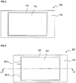
- a heat dissipation cartridge 300 includes a frame structure 100 injection-molded from a heat dissipation plastic to accommodate a pair of batteries.
- the frame structure 100 has an accommodating through-hole 110 provided in a central area and a seating portion 120 provided on walls of the accommodating through-hole 110 to allow a pair of batteries to be accommodated.
- the seating portion 120 is comprised of projections protruding from the walls of the accommodating through-hole 110 to horizontally halve the walls of the accommodating through-hole 110.
- the seating portion 120 allows a pair of batteries to be inserted through the top and bottom portions of the frame structure 100, thereby being accommodated in the accommodating through-hole 110.
- the seating portion 120 may be provided along the walls of the accommodating through-hole 110. In some cases, the seating portion 120 may be provided as a plurality of separate portions distributed on a plurality of areas of the walls of the accommodating through-hole 110.
- the batteries may be thin pouch batteries that have high energy concentration, enable high-power driving, and are electrically charged and discharged.
- Such pouch batteries are respectively fabricated by putting two electrodes, a separator, and a dielectric into a pouch and then sealing the pouch.
- the heat dissipation plastic is implemented as a non-insulation moldable resin in which an electrically-conductive heat sink filler made of graphene, carbon, or the like is distributed or an insulation moldable resin in which an insulating heat sink filler made of BN, AIN, MgO, Al 2 O 3 , SiO 2 , or the like is distributed.
- the heat dissipation plastic may generally be defined as an injection moldable insulating heat dissipation plastic including the insulating heat sink filler. Such a heat dissipation plastic dissipates heat transferred thereto via the insulating heat sink filler and has insulation due to the insulating heat sink filler and the resin.
- the heat dissipation cartridge 300 including the heat sink filler can dissipate heat generated during charging and discharging of the batteries.
- heat transferred to the heat dissipation cartridge 300 is removed by a heat exchanger.
- the heat exchanger may be any heat exchanger that can lower the temperature of the heat dissipation cartridge 300.
- Examples of the heat exchanger may be, but are not limited to, an air-cooling heat exchanger, such as a cooling fan, and a water-cooling heat exchanger using cooling water.
- the present invention has an advantage in that heat generated by the batteries can be efficiently dissipated using the heat dissipation cartridge 300 to which the batteries are fitted.
- the heat dissipation cartridge 300 seats and accommodates a first battery 201 in one of the halved areas of the accommodating through-hole 110 by inserting the first battery 201 into the seating portion 120 from above the frame structure 100, and seats and accommodates a second battery (not shown) in the other halved area of the accommodating through-hole 110 by inserting the second battery into the seating portion 120 from below the frame structure 100.
- electrode terminals of the first and second batteries 201 are in close contact with the frame structure 100, instead of remaining within the accommodating through-hole 110. As illustrated in FIG. 2 , the electrode terminals 201a and 201b of the first battery 201 are in close contact with the frame structure 100 of the heat dissipation cartridge.
- the first and second batteries 201 are pouch batteries, more heat is generated by peripheral areas than by inner areas of the pouch batteries.
- the present invention has a structural characteristic in that the seating portion 120 of the frame structure 100 is located between the peripheral area of the first battery 201 and the peripheral area of the second battery in order to dissipate heat, generated during charging and discharging of the first and second batteries 201, through the peripheral areas of the first and second batteries 201.
- FIG. 3 is a cross-sectional view taken along line a-a' in FIG. 2 in order to illustrate a position in which a pair of batteries are fitted to the heat dissipation cartridge according to the first embodiment of the present invention.
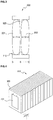
- the heat dissipation cartridge 300 accommodates first and second batteries 201 and 202 in the accommodating through-hole 110 of the frame structure 100.
- the accommodating through-hole 110 of the heat dissipation cartridge 300 may be divided into two areas by the seating portion 120 located between the peripheries of the first and second batteries 201 and 202, such that the first and second batteries 201 and 202 may be accommodated in the divided two areas, thereby leading to proper assembly alignment.
- the heat dissipation cartridge 300 is designed such that two batteries, i.e. the first and second batteries 201 and 202, are accommodated in the accommodating through-hole 110.
- the depth D of the accommodating through-hole 110 of the heat dissipation cartridge 300 may be substantially the same as or slightly greater than a total thickness t1+t2 of the two batteries 201 and 202.
- a plurality of heat dissipation cartridges 300 according to the first embodiment of the present invention may be stacked on one another, thereby providing a battery pack 510 for an electric vehicle.
- the present invention can provide the battery pack 510 for an electric vehicle, assembled by stacking the plurality of heat dissipation cartridges 300, with a pair of batteries 201 being fitted to each of the heat dissipation cartridges 300.
- the thickness of the battery pack 510 for an electric vehicle may be substantially the same as the thickness of the stacked heat dissipation cartridges 300 (i.e. the thickness t of the heat dissipation cartridge 300 illustrated in FIG. 4 is substantially the same as the thickness of a pair of batteries). Accordingly, the battery pack 510 for an electric vehicle according to the present invention can have a slim and thin profile and also be lightweight, thereby advantageously obtaining high capacity.
- the battery pack for an electric vehicle is provided with one hundred fifty (150) batteries
- heat dissipation fins or heat dissipation plates of the related art made of aluminum (Al) are sandwiched between the batteries
- one hundred forty nine (149) heat dissipation fins or plates are necessary. This may accordingly make it impossible to reduce the weight and thickness of the battery pack. Since a predetermined number of batteries equal to the volumes occupied by the 149 heat dissipation fins or plates cannot be fitted, the capacity of the battery pack is reduced.
- a heat dissipation metal plate 150 having high heat conductivity may be insert-molded in the frame structure 100 of the heat dissipation cartridge.
- the heat dissipation metal plate 150 may be insert-molded in an area of the frame structure 100 adjacent to the seating portion 120. More specifically, the heat dissipation metal plate 150 may be insert-molded in an area of the frame structure 100 corresponding to the seating portion 120, i.e. an area of the frame structure 100 facing the seating portion 120 protruding from the walls of the accommodating through-hole of the frame structure 100, such that heat generated by the batteries can be rapidly dissipated by the seating portion 120 and the heat dissipation metal plate 150.
- the heat dissipation metal plate 150 may be made of Al or an Al alloy, which has superior heat conductivity while being inexpensive.
- the heat dissipation metal plate 150 may be insert-molded in a position most adjacent to the seating portion 120.
- one surface of the insert-molded heat dissipation metal plate 150 is exposed externally to be in contact with a heat dissipation module.
- the heat dissipation metal plate 150 may be located on the frame structure 100 below the seating portion 120, such that heat transferred to the seating portion 120 from the batteries can be rapidly transferred to the heat exchanger 170 of the heat dissipation module through the heat dissipation metal plate 150.
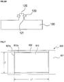
- a thermal interface material (TIM) 130 may be provided to surround the seating portion 120 of the frame structure 100 by insert molding.
- the seating portion 120 may be provided with coupling recesses 121, and TIMs 130 may be fitted to the coupling recesses 121.
- TIM 130 When the TIM 130 is insert-molded on the seating portion 120 or TIMs 130 are fitted to the coupling recesses 121 as described above, contact heat resistance may be reduced and an air gap between a pair of batteries may be reduced, thereby facilitating heat dissipation to the outside heat exchanger.
- the TIM 130 may be implemented as one of a variety of examples, such as heat dissipation grease, a heat dissipation sheet, a metal plate, and a thermally conductive adhesive.
- a heat dissipation cartridge 600 according to a second embodiment of the present invention is provided by combining a breakthrough cartridge structure and a breakthrough material, i.e. a greater number of batteries can be mounted in the same area due to improved battery mounting efficiency, and manufacturing cost can be reduced due to an aluminum frame being insert-molded in a heat dissipating molded plastic structure.
- the heat dissipation cartridge 600 has a frame structure including an accommodating through-hole 610 provided in a central area to accommodate a pair of batteries and seating portions 601a and 602a provided on walls of the accommodating through-hole 610 to seat the pair of batteries therein.
- the frame structure is molded from a heat dissipation plastic in which aluminum frames 602 is insert-molded.
- the frame structure includes heat dissipation plastic frames 601 and the aluminum frames 602.
- the heat dissipation plastic frames 601 have the seating portions 601a and 602a surrounding the accommodating through-hole 610 in which the pair of batteries are accommodated, and are disposed on both longitudinal ends of the accommodating through-hole 610.
- the pair of aluminum frames 602 is provided integrally on outer portions of the seating portions 602a in the longitudinal direction of the heat dissipation plastic frames 601.
- the batteries are rectangular-shaped, and thus the accommodating through-hole 610 and the seating portions 601a and 602a are rectangular-shaped.
- the rectangular seating portions 601a and 602a are comprised of the pair of first seating portions 601a disposed to face each other in the longitudinal direction of the accommodating through-hole 610 and the pair of second seating portions 602a disposed in the longitudinal direction of the accommodating through-hole 610 to connect both ends of the first seating portions 601a.
- the frame structure is also a rectangular frame structure, in which the length L1 of the aluminum frames 602 is longer than the length L2 of the heat dissipation plastic frames 601.
- the heat dissipation cartridge 600 can be provided by injection-molding the heat dissipation plastic frames 601 by inserting the inexpensive aluminum frames 602 in the aluminum frames 602, thereby significantly reducing manufacturing cost.
- a heat sink filler distributed in a resin of the heat dissipation plastic may be concentrated in a local area in the heat dissipation cartridge 600 during injection of the heat dissipation plastic into a mold, since the heavier heat sink filler has inferior flowability to the resin.
- shorter frame areas of the heat dissipation cartridge 600 are provided as the heat dissipation plastic frames 601 by injection-molding the heat dissipation plastic, while longer frame areas of the heat dissipation cartridge 600 are provided by inserting aluminum frames 602. This can reduce the magnitude of injection molding, such that the heat dissipation plastic frames 601 can be imparted with more uniform heat dissipation characteristics.
- the aluminum frames 602 can improve heat dissipation characteristics of the heat dissipation cartridge 600, due to a higher heat conduction characteristic than the heat dissipation plastic frames 601.
- the frame structure when the frame structure is manufactured by injection-molding the heat dissipation plastic frames 601 by inserting the aluminum frames 602 therein as in the present invention, instead of being provided only using the heat dissipation plastic frames 601 injection-molded from the heat dissipation plastic, the frame structure can have superior strength and can prevent deformations, such as distortion, due to external force.
- each of the heat dissipation plastic frames 601 and the aluminum frames 602 has a wall of the accommodating through-hole 610, and the first and second seating portions 601a and 602a are provided on the walls.
- the seating portions 601a and 602a are projections protruding from the walls of the accommodating through-hole 610 to horizontally halve the walls of the accommodating through-hole 610.
- the seating portion 601a and 602a allow a pair of batteries to be inserted through the top and bottom portions of the frame structure, thereby being accommodated in the accommodating through-hole 610.
- the seating portions 601a and 602a may be provided along the walls of the accommodating through-hole 610. In some cases, the seating portions 601a and 602a may be provided as a plurality of separate portions distributed on a plurality of areas of the walls of the accommodating through-hole 610.
- the batteries may be pouch batteries as in the first embodiment, while the heat dissipation plastic may be implemented as a non-insulation moldable resin in which an electrically-conductive heat sink filler is distributed or an insulation moldable resin in which an insulating heat sink filler is distributed.
- the heat dissipation plastic dissipates transferred heat using the insulating heat sink filler and has insulation due to the insulating heat sink filler and resin.
- the heat dissipation cartridge 600 including the heat sink filler can dissipate heat generated during charging and discharging of the batteries.
- heat transferred to the heat dissipation cartridge 600 is removed by a heat exchanger.
- the heat exchanger may be any heat exchanger that can lower the temperature of the heat dissipation cartridge 600.
- Examples of the heat exchanger may be, but are not limited to, an air-cooling heat exchanger, such as a cooling fan, and a water-cooling heat exchanger using cooling water.
- the present invention has an advantage in that heat generated by the batteries can be efficiently dissipated using the heat dissipation cartridge 600 to which the batteries are fitted.
- the heat dissipation cartridge 600 seats and accommodates a first battery 201 in one of the halved areas of the accommodating through-hole 610 by inserting the first battery 201 into the seating portions 601a and 602a from above the frame structure, and seats and accommodates a second battery (not shown) in the other halved area of the accommodating through-hole 610 by inserting the second battery into the seating portions 601a and 602a from below the frame structure.
- electrode terminals of the first and second batteries 201 are in close contact with the frame structure, instead of remaining within the accommodating through-hole 610. As illustrated in FIG. 8 , the electrode terminals 201a and 201b of the first battery 201 are in close contact with the heat dissipation plastic frames 601 of the heat dissipation cartridge 600.
- the seating portions 601a and 602a are provided on the heat dissipation frames 610 and the aluminum frames 602.
- the first and second batteries 201 are pouch batteries, more heat is generated by peripheral areas than by inner areas of the pouch batteries.
- the present invention has a structural characteristic in that the seating portions 601a and 602a of the frame structure are located between the peripheral area of the first battery 201 and the peripheral area of the second battery in order to dissipate heat, generated during charging and discharging of the first and second batteries 201, through the peripheral areas of the first and second batteries 201.
- FIG. 9 is a cross-sectional view taken along line b-b' in FIG. 8 in order to illustrate a position in which a pair of batteries are fitted to the heat dissipation cartridge according to the second embodiment of the present invention.
- the heat dissipation cartridge 600 accommodates first and second batteries 201 and 202 in the accommodating through-hole 610 of the frame structure.
- the accommodating through-hole 610 of the heat dissipation cartridge 600 may be divided into two areas by the seating portion 120 located between the peripheries of the first and second batteries 201 and 202, such that the first and second batteries 201 and 202 may be accommodated in the divided two areas, thereby leading to proper assembly alignment.
- the seating portions 601a provided on the heat dissipation plastic frames 601 are illustrated.
- the heat dissipation cartridge 600 is designed such that two batteries, i.e. the first and second batteries 201 and 202 are accommodated in the accommodating through-hole 610.
- the depth D of the accommodating through-hole 610 of the heat dissipation cartridge 600 may be substantially the same as or slightly greater than a total thickness t1+t2 of the two batteries 201 and 202.
- FIG. 10 is a cross-sectional view illustrating a portion of the aluminum frame used in the heat dissipation cartridge according to the second embodiment of the present invention, coated with an oxide coating layer.
- the present invention can provide an oxide coating layer 603 made of alumina (Al 2 O 3 ) on the surface of the aluminum frame 602 by anodizing the aluminum frame 602.
- oxide coating layer 603 made of alumina (Al 2 O 3 ) on the surface of the aluminum frame 602 by anodizing the aluminum frame 602.
- the oxide coating layer 603 made of alumina can be provided by anodizing of the aluminum frame 602.
- the oxide coating layer 603 made of alumina can improve heat dissipation coefficient, i.e. a measure of heat dissipation capability, and have an insulation characteristic.
- the electrolyte may be an acidic electrolyte although not limited thereto, and an alkali electrolyte is usable. Sulfuric acid, oxalic acid, phosphoric acid, or a mixture thereof may be used as the acidic electrolyte.
- the thickness of the oxide coating layer 603 required for insulation may be adjusted by controlling the time and current density of anodizing.
- a plurality of heat dissipation cartridges 600 may be stacked on one another, thereby providing a battery pack 510 for an electric vehicle.
- the present invention can provide the battery pack 510 for an electric vehicle, assembled by stacking the plurality of heat dissipation cartridges 600, with the batteries 201 being fitted to each of the heat dissipation cartridges 600.
- the thickness of the battery pack 510 for an electric vehicle may be substantially the same as the thickness of the stacked heat dissipation cartridges 600 (i.e. the thickness t of the heat dissipation cartridge 600 illustrated in FIG. 5 is substantially the same as the thickness of a pair of batteries). Accordingly, the battery pack 510 for an electric vehicle according to the present invention can have a slim and thin profile and also be lightweight, thereby advantageously obtaining high capacity.
- the heat dissipation cartridge 600 according to the second embodiment of the present invention may further include heat dissipation metal plates insert-molded in areas of the heat dissipation plastic frames 601 facing the seating portions 601a protruding from the walls of the accommodating through-hole.
- a heat dissipation metal plate 150 having high heat conductivity may be insert-molded in the heat dissipation plastic frame 601.
- the heat dissipation plate 150 may be insert-molded in an area of the heat dissipation plastic frame 601 adjacent to the seating portion 601a. More specifically, the heat dissipation plate 150 may be insert-molded in an area of the heat dissipation plastic frame 601 corresponding to the seating portion 601a, i.e. an area of the heat dissipation plastic frame 601 facing the seating portion 601a protruding from the wall of the accommodating through-hole, such that heat generated by the batteries can be rapidly dissipated by the seating portion 601a and the heat dissipation plate 150.
- the heat dissipation plate 150 may be made of Al or an Al alloy, which has superior heat conductivity while being inexpensive.
- the heat dissipation plate 150 may be insert-molded in a position most adjacent to the seating portion 601a.
- one surface of the insert-molded heat dissipation metal plate 150 is exposed externally to be in contact with a heat dissipation module.
- the heat dissipation plate 150 may be located on the heat dissipation plastic frame 601 below the seating portion 601a, such that heat transferred to the seating portion 601a from the batteries can be rapidly transferred to the heat exchanger 170 through the heat dissipation plate 150.
- a TIM 130 may be provided on the seating portion 601a of the heat dissipation plastic frame 601 by insert molding.
- the seating portion 601a may be provided with coupling recesses 121, and TIMs 130 may be fitted to the coupling recesses 121.
- TIM 130 When the TIM 130 is insert-molded on the seating portion 601a or TIMs 130 are fitted to the coupling recesses, contact heat resistance may be reduced and an air gap between a pair of batteries may be reduced, thereby facilitating heat dissipation to the outside heat exchanger.
- the TIM 130 may be implemented as one of a variety of examples, such as heat dissipation grease, a heat dissipation sheet, a metal plate, and a thermally conductive adhesive.
- FIG. 14 is a top view illustrating a portion of the heat dissipation plastic frame of the heat dissipation plastic according to the second embodiment of the present invention, on which an insulating plastic is provided.
- electrode terminals 201a and 201b of a pouch battery are placed on and attached to the heat dissipation plastic frame 601.
- the heat dissipation plastic frames 601 may be injection-molded by inserting insulating plastic plates 605 in areas on which the electrode terminals 201a and 201b of the pouch battery are placed.
- the electrode terminals 201a and 201b of the pouch battery are placed on and in contact with the insulating plastic plates 605.
- the heat dissipation cartridge and the battery pack according to the present invention can reduce manufacturing cost, improve heat dissipation performance, obtain uniform heat dissipation performance, obtain superior strength, and prevent deformation.
Landscapes
- Chemical & Material Sciences (AREA)
- Chemical Kinetics & Catalysis (AREA)
- Electrochemistry (AREA)
- General Chemical & Material Sciences (AREA)
- Engineering & Computer Science (AREA)
- Manufacturing & Machinery (AREA)
- Inorganic Chemistry (AREA)
- Battery Mounting, Suspending (AREA)
- Secondary Cells (AREA)
Applications Claiming Priority (3)
| Application Number | Priority Date | Filing Date | Title |
|---|---|---|---|
| KR1020160037556A KR20170113904A (ko) | 2016-03-29 | 2016-03-29 | 방열 카트리지 및 이를 이용한 전기자동차용 전지팩 |
| KR1020160037559A KR20170113905A (ko) | 2016-03-29 | 2016-03-29 | 방열 카트리지 및 이를 이용한 전기자동차용 전지팩 |
| PCT/KR2017/003398 WO2017171389A2 (fr) | 2016-03-29 | 2017-03-29 | Cartouche de rayonnement thermique, et bloc-batterie pour véhicule électrique l'utilisant |
Publications (4)
| Publication Number | Publication Date |
|---|---|
| EP3442075A2 true EP3442075A2 (fr) | 2019-02-13 |
| EP3442075A4 EP3442075A4 (fr) | 2019-10-30 |
| EP3442075C0 EP3442075C0 (fr) | 2025-11-05 |
| EP3442075B1 EP3442075B1 (fr) | 2025-11-05 |
Family
ID=59966229
Family Applications (1)
| Application Number | Title | Priority Date | Filing Date |
|---|---|---|---|
| EP17775813.3A Active EP3442075B1 (fr) | 2016-03-29 | 2017-03-29 | Cartouche de rayonnement thermique, et bloc-batterie pour véhicule électrique l'utilisant |
Country Status (4)
| Country | Link |
|---|---|
| US (1) | US11177518B2 (fr) |
| EP (1) | EP3442075B1 (fr) |
| CN (1) | CN108886185B (fr) |
| WO (1) | WO2017171389A2 (fr) |
Families Citing this family (3)
| Publication number | Priority date | Publication date | Assignee | Title |
|---|---|---|---|---|
| KR102256103B1 (ko) * | 2018-09-12 | 2021-05-25 | 주식회사 엘지에너지솔루션 | 배터리 모듈 및 이를 포함하는 배터리 팩 |
| KR102378527B1 (ko) | 2018-12-05 | 2022-03-23 | 주식회사 엘지에너지솔루션 | 전지 모듈 및 그 제조 방법 |
| CN114243150B (zh) * | 2021-11-05 | 2024-04-26 | 佛山市实达科技有限公司 | 一种锂离子蓄电池组 |
Family Cites Families (11)
| Publication number | Priority date | Publication date | Assignee | Title |
|---|---|---|---|---|
| KR100998845B1 (ko) * | 2007-11-09 | 2010-12-08 | 주식회사 엘지화학 | 방열특성의 전지모듈, 열교환 부재 및 이를 이용하는 중대형 전지팩 |
| KR20090107443A (ko) | 2008-04-08 | 2009-10-13 | 쏘씨에떼 드 베이뀔르 엘렉트리끄 | 가요성의 발전 소자와 상기 발전 소자들의 기계적, 열적 조절 시스템을 포함하는 전기 배터리 |
| EP2416439B1 (fr) * | 2009-04-01 | 2015-07-29 | LG Chem, Ltd. | Module de batterie comportant une radiation thermique excellente et bloc-batteries celui-ci |
| KR101106373B1 (ko) * | 2009-11-19 | 2012-01-18 | 에스비리모티브 주식회사 | 배터리 팩 |
| KR101431717B1 (ko) * | 2012-02-06 | 2014-08-26 | 주식회사 엘지화학 | 신규한 구조의 버스 바 |
| CN104285315B (zh) | 2012-05-08 | 2016-11-16 | 株式会社Lg化学 | 具有高效冷却结构的电池模块 |
| KR101392799B1 (ko) * | 2012-06-07 | 2014-05-14 | 주식회사 엘지화학 | 안정성이 향상된 구조 및 높은 냉각 효율성을 갖는 전지모듈 |
| KR101729213B1 (ko) * | 2013-10-23 | 2017-04-21 | 주식회사 엘지화학 | 진동 특성이 향상된 배터리 모듈 및 이에 적용되는 프레임 카트리지 조립체 |
| KR101739301B1 (ko) * | 2013-12-10 | 2017-05-24 | 삼성에스디아이 주식회사 | 배터리 모듈 |
| KR101773105B1 (ko) * | 2014-07-31 | 2017-08-30 | 주식회사 엘지화학 | 배터리 모듈 |
| KR101769109B1 (ko) * | 2014-09-04 | 2017-08-17 | 주식회사 엘지화학 | 이차 전지용 카트리지를 포함하는 배터리 팩 |
-
2017
- 2017-03-29 US US16/086,918 patent/US11177518B2/en active Active
- 2017-03-29 CN CN201780020716.XA patent/CN108886185B/zh active Active
- 2017-03-29 WO PCT/KR2017/003398 patent/WO2017171389A2/fr not_active Ceased
- 2017-03-29 EP EP17775813.3A patent/EP3442075B1/fr active Active
Also Published As
| Publication number | Publication date |
|---|---|
| WO2017171389A3 (fr) | 2018-08-02 |
| CN108886185A (zh) | 2018-11-23 |
| US20190109353A1 (en) | 2019-04-11 |
| EP3442075A4 (fr) | 2019-10-30 |
| EP3442075C0 (fr) | 2025-11-05 |
| US11177518B2 (en) | 2021-11-16 |
| WO2017171389A2 (fr) | 2017-10-05 |
| CN108886185B (zh) | 2022-11-15 |
| EP3442075B1 (fr) | 2025-11-05 |
Similar Documents
| Publication | Publication Date | Title |
|---|---|---|
| CN108886184B (zh) | 散热模块及利用其的电动汽车用电池组 | |
| CN102422459B (zh) | 包括弹性加压构件的电池盒以及包括该电池盒的电池模块 | |
| US10446891B2 (en) | Submodule and battery module having the same | |
| KR102067710B1 (ko) | 배터리 모듈 및 이를 포함하는 배터리 팩, 자동차 | |
| CN102484300B (zh) | 其上安装有温度传感器的电池模块和包括该电池模块的中大型电池组 | |
| CN209843907U (zh) | 二次电池 | |
| CN104285315B (zh) | 具有高效冷却结构的电池模块 | |
| CN104412439B (zh) | 具有间接空气冷却结构的电池模块 | |
| JP6608653B2 (ja) | 電池モジュール | |
| KR101533992B1 (ko) | 전지모듈 | |
| CN109075410B (zh) | 散热盒及利用其的电动汽车用电池组 | |
| KR20220114801A (ko) | 배터리 모듈 | |
| EP3442075B1 (fr) | Cartouche de rayonnement thermique, et bloc-batterie pour véhicule électrique l'utilisant | |
| CN114142131B (zh) | 电池模块 | |
| KR101976588B1 (ko) | 조립형 방열 카트리지 및 이를 이용한 전기자동차용 전지팩 | |
| KR101966183B1 (ko) | 방열 카트리지 및 이를 이용한 전기자동차용 전지팩 | |
| KR101976589B1 (ko) | 방열 카트리지 및 이를 이용한 전기자동차용 전지팩 | |
| CN115398714A (zh) | 具有改善的电池电芯之间的温度均匀性的电池模块 | |
| KR20170113904A (ko) | 방열 카트리지 및 이를 이용한 전기자동차용 전지팩 | |
| KR20170113905A (ko) | 방열 카트리지 및 이를 이용한 전기자동차용 전지팩 | |
| CN117480670B (en) | Battery module | |
| WO2023276656A1 (fr) | Module de batterie |
Legal Events
| Date | Code | Title | Description |
|---|---|---|---|
| STAA | Information on the status of an ep patent application or granted ep patent |
Free format text: STATUS: THE INTERNATIONAL PUBLICATION HAS BEEN MADE |
|
| PUAI | Public reference made under article 153(3) epc to a published international application that has entered the european phase |
Free format text: ORIGINAL CODE: 0009012 |
|
| STAA | Information on the status of an ep patent application or granted ep patent |
Free format text: STATUS: REQUEST FOR EXAMINATION WAS MADE |
|
| 17P | Request for examination filed |
Effective date: 20180926 |
|
| AK | Designated contracting states |
Kind code of ref document: A2 Designated state(s): AL AT BE BG CH CY CZ DE DK EE ES FI FR GB GR HR HU IE IS IT LI LT LU LV MC MK MT NL NO PL PT RO RS SE SI SK SM TR |
|
| AX | Request for extension of the european patent |
Extension state: BA ME |
|
| RIN1 | Information on inventor provided before grant (corrected) |
Inventor name: HWANG, SEUNG JAE |
|
| DAV | Request for validation of the european patent (deleted) | ||
| DAX | Request for extension of the european patent (deleted) | ||
| A4 | Supplementary search report drawn up and despatched |
Effective date: 20191002 |
|
| RIC1 | Information provided on ipc code assigned before grant |
Ipc: H01M 10/647 20140101ALI20190926BHEP Ipc: H01M 10/625 20140101ALI20190926BHEP Ipc: H01M 2/10 20060101ALI20190926BHEP Ipc: H01M 10/653 20140101ALI20190926BHEP Ipc: H01M 10/6551 20140101AFI20190926BHEP Ipc: H01M 10/613 20140101ALI20190926BHEP Ipc: H01M 10/655 20140101ALI20190926BHEP |
|
| STAA | Information on the status of an ep patent application or granted ep patent |
Free format text: STATUS: EXAMINATION IS IN PROGRESS |
|
| 17Q | First examination report despatched |
Effective date: 20230307 |
|
| GRAP | Despatch of communication of intention to grant a patent |
Free format text: ORIGINAL CODE: EPIDOSNIGR1 |
|
| STAA | Information on the status of an ep patent application or granted ep patent |
Free format text: STATUS: GRANT OF PATENT IS INTENDED |
|
| RIC1 | Information provided on ipc code assigned before grant |
Ipc: H01M 10/6551 20140101AFI20250821BHEP Ipc: H01M 10/613 20140101ALI20250821BHEP Ipc: H01M 10/625 20140101ALI20250821BHEP Ipc: H01M 10/647 20140101ALI20250821BHEP Ipc: H01M 10/653 20140101ALI20250821BHEP Ipc: H01M 10/655 20140101ALI20250821BHEP Ipc: H01M 50/211 20210101ALI20250821BHEP Ipc: H01M 50/224 20210101ALI20250821BHEP Ipc: H01M 50/227 20210101ALI20250821BHEP Ipc: H01M 50/24 20210101ALI20250821BHEP |
|
| GRAS | Grant fee paid |
Free format text: ORIGINAL CODE: EPIDOSNIGR3 |
|
| GRAA | (expected) grant |
Free format text: ORIGINAL CODE: 0009210 |
|
| STAA | Information on the status of an ep patent application or granted ep patent |
Free format text: STATUS: THE PATENT HAS BEEN GRANTED |
|
| INTG | Intention to grant announced |
Effective date: 20250911 |
|
| AK | Designated contracting states |
Kind code of ref document: B1 Designated state(s): AL AT BE BG CH CY CZ DE DK EE ES FI FR GB GR HR HU IE IS IT LI LT LU LV MC MK MT NL NO PL PT RO RS SE SI SK SM TR |
|
| REG | Reference to a national code |
Ref country code: CH Ref legal event code: F10 Free format text: ST27 STATUS EVENT CODE: U-0-0-F10-F00 (AS PROVIDED BY THE NATIONAL OFFICE) Effective date: 20251105 Ref country code: GB Ref legal event code: FG4D |
|
| REG | Reference to a national code |
Ref country code: IE Ref legal event code: FG4D |
|
| U01 | Request for unitary effect filed |
Effective date: 20251117 |
|
| U07 | Unitary effect registered |
Designated state(s): AT BE BG DE DK EE FI FR IT LT LU LV MT NL PT RO SE SI Effective date: 20251121 |
|
| PGFP | Annual fee paid to national office [announced via postgrant information from national office to epo] |
Ref country code: GB Payment date: 20260224 Year of fee payment: 10 |
|
| PG25 | Lapsed in a contracting state [announced via postgrant information from national office to epo] |
Ref country code: ES Free format text: LAPSE BECAUSE OF FAILURE TO SUBMIT A TRANSLATION OF THE DESCRIPTION OR TO PAY THE FEE WITHIN THE PRESCRIBED TIME-LIMIT Effective date: 20251105 |
|
| PG25 | Lapsed in a contracting state [announced via postgrant information from national office to epo] |
Ref country code: NO Free format text: LAPSE BECAUSE OF FAILURE TO SUBMIT A TRANSLATION OF THE DESCRIPTION OR TO PAY THE FEE WITHIN THE PRESCRIBED TIME-LIMIT Effective date: 20260205 |
|
| PG25 | Lapsed in a contracting state [announced via postgrant information from national office to epo] |
Ref country code: HR Free format text: LAPSE BECAUSE OF FAILURE TO SUBMIT A TRANSLATION OF THE DESCRIPTION OR TO PAY THE FEE WITHIN THE PRESCRIBED TIME-LIMIT Effective date: 20251105 |
|
| PG25 | Lapsed in a contracting state [announced via postgrant information from national office to epo] |
Ref country code: RS Free format text: LAPSE BECAUSE OF FAILURE TO SUBMIT A TRANSLATION OF THE DESCRIPTION OR TO PAY THE FEE WITHIN THE PRESCRIBED TIME-LIMIT Effective date: 20260205 |
|
| PG25 | Lapsed in a contracting state [announced via postgrant information from national office to epo] |
Ref country code: IS Free format text: LAPSE BECAUSE OF FAILURE TO SUBMIT A TRANSLATION OF THE DESCRIPTION OR TO PAY THE FEE WITHIN THE PRESCRIBED TIME-LIMIT Effective date: 20260305 |
|
| PG25 | Lapsed in a contracting state [announced via postgrant information from national office to epo] |
Ref country code: PL Free format text: LAPSE BECAUSE OF FAILURE TO SUBMIT A TRANSLATION OF THE DESCRIPTION OR TO PAY THE FEE WITHIN THE PRESCRIBED TIME-LIMIT Effective date: 20251105 |
|
| U20 | Renewal fee for the european patent with unitary effect paid |
Year of fee payment: 10 Effective date: 20260323 |