EP3442103B1 - Actionneur oscillant linéaire - Google Patents
Actionneur oscillant linéaire Download PDFInfo
- Publication number
- EP3442103B1 EP3442103B1 EP18197663.0A EP18197663A EP3442103B1 EP 3442103 B1 EP3442103 B1 EP 3442103B1 EP 18197663 A EP18197663 A EP 18197663A EP 3442103 B1 EP3442103 B1 EP 3442103B1
- Authority
- EP
- European Patent Office
- Prior art keywords
- moving
- spring section
- coupling
- section
- spring
- Prior art date
- Legal status (The legal status is an assumption and is not a legal conclusion. Google has not performed a legal analysis and makes no representation as to the accuracy of the status listed.)
- Active
Links
Images





Classifications
-
- H—ELECTRICITY
- H02—GENERATION; CONVERSION OR DISTRIBUTION OF ELECTRIC POWER
- H02K—DYNAMO-ELECTRIC MACHINES
- H02K33/00—Motors with reciprocating, oscillating or vibrating magnet, armature or coil system
- H02K33/16—Motors with reciprocating, oscillating or vibrating magnet, armature or coil system with polarised armatures moving in alternate directions by reversal or energisation of a single coil system
-
- B—PERFORMING OPERATIONS; TRANSPORTING
- B26—HAND CUTTING TOOLS; CUTTING; SEVERING
- B26B—HAND-HELD CUTTING TOOLS NOT OTHERWISE PROVIDED FOR
- B26B19/00—Clippers or shavers operating with a plurality of cutting edges, e.g. hair clippers, dry shavers
- B26B19/28—Drive layout for hair clippers or dry shavers, e.g. providing for electromotive drive
- B26B19/282—Motors without a rotating central drive shaft, e.g. linear motors
-
- B—PERFORMING OPERATIONS; TRANSPORTING
- B26—HAND CUTTING TOOLS; CUTTING; SEVERING
- B26B—HAND-HELD CUTTING TOOLS NOT OTHERWISE PROVIDED FOR
- B26B19/00—Clippers or shavers operating with a plurality of cutting edges, e.g. hair clippers, dry shavers
- B26B19/28—Drive layout for hair clippers or dry shavers, e.g. providing for electromotive drive
- B26B19/288—Balance by opposing oscillation
Definitions
- the present invention relates to a linear oscillatory actuator that, for example, can be used as a drive source of an electric shaver.
- this linear oscillatory actuator 50 includes a stator block 51 having an electromagnet 52, two moving elements 60 each having a permanent magnet 61 disposed oppositely to the electromagnet 52, two pairs of connecting plates 70 that connect the moving elements 60 with the stator block 51, respectively, and a pair of coupling spring portions 80 that couple the two moving elements 60.
- Magnetic pole faces of the electromagnetic 52 in the stator block 51 are disposed at a position opposite to the permanent magnets 61 in the two moving elements 60.
- Each of the moving elements 60 includes a moving-side housing 64, and is integrally formed with the pair of connecting plates 70 so as to reciprocate independently in its reciprocating direction (M direction) due to deflection of the pair of connecting plates 70.
- Both of the permanent magnets 61 of the moving elements 60 are disposed oppositely to the magnetic pole faces of the electromagnet 52 in the stator block 51 with a predetermined gap therebetween.
- One of the permanent magnet 61 is disposed in reversed polarity to another of the permanent magnet 61, so that they are subject to opposite magnetic forces (an attractive force and a repelling force) caused by a magnetic field produced by the electromagnet 52, respectively. Therefore, opposite drive forces apply to the moving elements 60 in the reciprocating direction (M direction), respectively, when the electromagnet 52 is activated.
- the connecting plates 70 in a pair are disposed at both ends of the moving element 60, respectively.
- the connecting plates 70 are integrally formed with the moving-side member 64 of the moving element 60.
- Each of the connecting plates 70 includes an upper extending portion 73, a lower extending portion 74, and an elastic planar portion 71 that is formed between the extending portions 73 and 74.
- the connecting plates 70 are elastic suspensions for supporting the moving element 60.
- the upper extending portion 73 connects with the moving housing 64, and the lower extending portion 74 connects with a fixed-side base 54 of the stator block 51.
- the elastic planar portion 71 consists of two spring plates 71a and 71b that are aligned parallel to each other with a predetermined distance, and connects the upper extending portion 73 with the lower extending portion 74.
- a continuous portion 76 between the upper extending portion 73 and the spring plates 71b (the elastic planar portion 71) is formed into a simple curved shape with a small curvature, as shown in Figs. 7 and 8 .
- Each of the coupling spring portions 80 has a C-ring shape and is connected with the pair of moving elements 60 only at its both ends, respectively.
- Each of the coupling spring portions 80 has a symmetrical shape in a center plane between the pair of moving elements 60.
- EP 2 194 635 A1 discloses a vibrating linear actuator in which a reciprocatingly driving magnetic block is formed as a movable element.
- First and second magnetic blocks are provided with first and second drive elements, respectively, and the magnetic blocks are reciprocatingly driven in the mutually reversed phases.
- first and second output parts are provided on the first drive element
- third and fourth output parts are provided on the second drive element
- the output parts and the output parts are disposed on the mutually opposite sides of a line passing through the center of gravity.
- JP 2010-166687 A provides a vibrating linear actuator in which back yokes are made thinner, resulting in the miniaturization of moving elements and the miniaturization of a whole actuator.
- e vibrating linear actuator includes a pair of moving elements, which are each provided with permanent magnets and back yokes, arrayed side by side adjacent to each other and are driven in a direction perpendicularly intersecting the array direction, and an electromagnetic core block, which includes an electromagnet and is arranged facing the moving elements via a gap.
- Each moving element is structured by inserting the respective back yoke from outside of the array direction of the moving elements into a fitting space provided in a moving element housing made of a resin, and each back yoke includes a magnetic circuit structured part at the center in the moving direction of the moving element and includes a pair of arm parts extending from the rear end of the insertion direction toward the front end at both ends thereof. At the deep end in the insertion direction of the fitting space of the moving element housing, facing walls are provided that face the tip end of the arm parts.
- US 2005/0173662 A1 shows another vibration type linear actuator.
- the oscillation type linear actuator for reciprocally moving a plurality of moving members held in parallel with each other in a predetermined direction owing to electromagnetic action between a stator and them, two moving members reciprocally moving in opposite phases with each other are coupled by a coupling member having spring function, and a non-displacing portion of a plate spring portion of the coupling member which is not displaced substantially is restricted by a stopper.
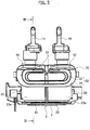
- the linear oscillatory actuator 1 includes a stator block (magnetic pole forming portion) 2 having an electromagnet 4, two moving elements (magnetic blocks) 10 each having a permanent magnet 12 (see Fig. 2 ) disposed oppositely to the electromagnet 4, two pairs of connecting plates (elastic suspensions) 20 that connect the moving elements 10 with the stator block 2, respectively, and a pair of coupling spring portions 30 that couple the two moving elements 10.
- the coupling spring portions 30 are provided in a pair at both sides of the moving elements 10 in a reciprocating direction of the moving elements 10 in the present embodiment, but the coupling spring portion 30 may be provided singularly or in a plurality at any position capable of coupling the moving elements 10 reciprocatably.
- the stator block 2 includes a fixed-side base 3 made of synthetic resin.
- the electromagnet 4 is fixed on the fixed-side base 3.
- the electromagnet 4 includes a core 5 (see Fig. 4 ) made of material that can be magnetized, and a coil 7 that is wound around the core 5 with interposing a bobbin 6 made of material that cannot be magnetized. Alternating current is applied to the coil 7.
- Each of magnetic pole faces 5a of the core 5 is positioned oppositely to the permanent magnets 12 of the two moving elements 10.
- the pair of moving element 10 is aligned in a front-back direction with a gap therebetween.
- Each of the moving elements 10 includes a moving-side housing 11 made of synthetic resin, the permanent magnet 12, and a back yoke 13 made of material that can be magnetized.
- a drive element 14 is fixed on an upper surface of the moving-side housing 11 by screws or the like.
- an inner blade (not shown) is attached to the drive element 14.
- Each of the moving elements 10 is provided so as to reciprocate independently in its reciprocating direction (M direction) due to deflection of the pair of connecting plates 20.
- Both of the permanent magnets 12 of the moving elements 10 are disposed oppositely to the magnetic pole faces 5a of the electromagnet 4 with a predetermined gap therebetween.
- One of the permanent magnet 12 is disposed in reversed polarity to another of the permanent magnet 12, so that they are subject to opposite magnetic forces (an attractive force and a repelling force) caused by a magnetic field produced by the electromagnet 4, respectively. Therefore, opposite drive forces apply to the moving elements 10 in the reciprocating direction (M direction), respectively, when the electromagnet 4 is activated.
- the back yoke 13 is disposed on an opposite side of the permanent magnet 12 to the electromagnet 4.
- the connecting plates 20 in a pair are made of synthetic resin, and integrally formed with the moving-side housing 11.
- Each of the connecting plates 20 includes an upper extending portion 21, a lower extending portion 22, and an elastic planar portion 23 that is formed between the extending portions 21 and 22.
- the upper extending portions 21 in a pair are connected with both ends of the moving-side housing 11, respectively.
- the lower extending portions 22 in a pair are connected to the fixed-side base 3 of the stator block 2.
- An attachment protruded portion 22a is provided on each of the lower extending portions 22.
- the attachment protruded portion 22a is fixed to the fixed-side base 3 of the stator block 2 by screws or the like. Therefore, each of the moving elements 10 is supported by the connecting plates 20 in a lifted-up manner.
- the elastic planar portion 23 consists of two spring plates 23a and 23b that are aligned parallel to each other with a predetermined distance.
- the moving element 10 can reciprocate in the reciprocating direction (M direction) due to deflection of the two spring plates 23a and 23b.
- each of the spring plates 23a and 23b is planar and formed to have almost the same width as a width of the moving element 10 and the same height as a height from the fixed-side base 3 to the moving element 10.
- the spring plate 23a is disposed on a side of the coupling spring portion 30 (i.e. outside), and the spring plate 23b is disposed on a side of the moving-side housing 11 (i.e. inside).
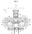
- a depressed portion 26 is formed at each continuous portion 25 between the upper extending portion 21 and the spring plate 23b (the elastic planar portion 23) as shown in Fig. 5 .
- the depressed portion 26 is depressed toward the moving element 10 (the moving-side housing 11).
- the depressed portion 26 is formed of a depressed opposite surface 27 that is depressed inward from an opposite surface 16 of the moving-side housing 11 to an intermediate portion 23c of the spring plate 23b (the elastic planar portion 23), and a curved surface 28 that extends continuously from an end (on a side of the upper extending portion 21) of the depressed opposite surface 27 to the spring plate 23b.
- the curved surface 28 has its sloped surface section near the moving-side housing 11.
- the depressed portion 26 is formed with almost the same width as the width of the moving element 10. Namely, each width of the depressed opposite surface 27 and the curved surface 28 is the same as the moving element 10.
- the depressed opposite surface 27 locates inward from the opposite surface 16, and extends along a width direction of the upper extending portion 21.
- the curved surface 28 is formed continuously from the (upper) end of the depressed opposite surface 27 to the spring plate 23b, and extends along the width direction of the upper extending portion 21.
- the coupling spring portions 30 in a pair are made of synthetic resin, and integrally formed with the connecting plates 20 and the moving-side housings 11.
- Each of the coupling spring portions 30 includes two coupling base sections 31 and a spring section 32 disposed between the two coupling base sections 31.
- the two coupling base sections 31 are fixed to the upper extending portions 21 of the connecting plates 20, respectively.
- the spring section 32 has an almost frame shape, and consists of an inner spring section 33 on its inner circumferential side and an outer spring section 34 on its outer circumferential side.
- the inner spring section 33 is integrally formed on an inner circumference of the outer spring section 34 near the moving elements 10, and has almost a half width of the outer spring section 34.
- the depressed portion 26 is formed at the continuous portion 25 of the connecting plate 20
- a molding portion of a die for forming the continuous portion 25 can be made thick. Therefore, strength of the die can be improved.
- the actuator 1 can be prevented from becoming large in size.
- Fig. 6 shows a modified example of a depressed portion 26A formed at the continuous portion 25.
- the depressed portion 26A is formed between the upper extending portion 21 and the spring plate 23b similarly to the above-described embodiment shown in Fig. 5 , and depressed toward the moving element 10 (the moving-side housing 11).
- the repressed portion 26A is formed by the depressed opposite surface 27 and a curved portion 28A that extend continuously.
- the depressed opposite surface 27 is depressed inward from the opposite surface 16 of the moving-side housing 11 to the intermediate portion 23c of the spring plate 23b, and extends along the width direction of the upper extending portion 21.
- the curved surface 28A extends continuously from an end (on a side of the upper extending portion 21) of the depressed opposite surface 27 to the spring plate 23b.
- the curved surface 28A has its sloped surface section near the spring plate 23a..
- the depressed portion 26A is formed at the continuous portion 25 of the connecting plate 20
- a molding portion of a die for forming the continuous portion 25 can be made thick. Therefore, strength of the die can be improved.
- the actuator 1 can be adapted to other uses.
- the magnetic pole forming portion (stator block) 2 that includes the electromagnet 4 is a fixed side and the magnetic blocks (moving elements) 10 that have the permanent magnets 12 are movable sides in the above-described embodiment.
- the magnetic pole forming portion 2 that includes the electromagnet 4 may be a movable side and the magnetic blocks 10 that have the permanent magnets 12 may be fixed sides.
- the magnetic pole forming portion 2 that includes the electromagnet 4 may be one movable side and the magnetic blocks 10 that have the permanent magnets 12 may be other movable sides.
- depressed portion 26 (26A) continuously formed along the entire width of the moving element 10 in the above-described embodiment, it is not needed to form the depressed portion 26 (26A) continuously.
- the depressed portion 26 (26A) can be formed discontinuously (e.g. intermittently) even if the depressed portion 26 (26A) can mitigate the stress and improve the strength.
- the elastic suspensions (connecting plates) 20, the coupling spring portions 30 and the moving elements 10 are formed integrally in the above-described embodiment.
- the elastic suspensions and the coupling spring portions 30 may be formed separately from the moving elements and then fixed to the moving elements by screws or the like.
- the electromagnet 4 is fixed on the fixed-side base 3 in the above-described embodiment.
- the electromagnet may be fixed to the fixed-side base with interposing a spring material.
- an inner blade(s) may be reciprocated via the drive element(s), or an outer blade(s) may be reciprocated by one of the plural moving elements.
Landscapes
- Engineering & Computer Science (AREA)
- Life Sciences & Earth Sciences (AREA)
- Forests & Forestry (AREA)
- Mechanical Engineering (AREA)
- Power Engineering (AREA)
- Reciprocating, Oscillating Or Vibrating Motors (AREA)
Claims (4)
- Actionneur oscillant linéaire (1) comprenant :une partie de formation de pôle magnétique (2) qui comprend un électroaimant (4) capable de générer différentes polarités de manière alternée lorsqu'il est activé et une base (3) sur laquelle l'électroaimant (4) est fixé ;au moins deux blocs magnétiques (10), dont chacun est disposé à l'opposé de la partie de formation de pôle magnétique (2) et comprend un aimant (12) destiné à être attiré ou repoussé par une polarité générée au niveau de la partie de formation de pôle magnétique (2) et effectue un mouvement de va-et-vient dans une direction de va-et-vient (M) par rapport à la partie de formation de pôle magnétique (2) ;au moins deux suspensions élastiques (20) qui supportent les blocs magnétiques (10) selon un mouvement de va-et-vient, respectivement ; etau moins une partie de ressort de couplage (30) qui couple les blocs magnétiques (10) selon un mouvement de va-et-vient, dans lequel chaque partie de ressort de couplage (30) comprend deux sections de base de couplage (31) et une section de ressort (32) disposée entre les deux sections de base de couplage (31),caractérisé en ce que :la section de ressort (32) se compose d'une section de ressort externe (34) et d'une section de ressort interne (33), dans lequel, lorsqu'elle est observée dans la direction de va-et-vient (M), une section transversale de la section de ressort interne (33) est sur un côté circonférentiel interne d'une section transversale de la section de ressort externe (34) ;dans lequel chacune parmi la section de ressort interne (33) et la section de ressort externe (34) a l'une des sections de base de couplage (31) raccordée à l'un des blocs magnétiques (10) et l'autre des sections de base de couplage (31) raccordée à l'autre des blocs magnétiques (10).
- Actionneur oscillant linéaire (1) selon la revendication 1, dans lequel la section transversale de chacune parmi la section de ressort interne (33) et la section de ressort externe (34), lorsqu'elle est observée dans la direction de va-et-vient (M), a une forme de C.
- Actionneur oscillant linéaire (1) selon la revendication 1 ou 2, dans lequel la section de ressort interne (33) est emboitée à l'intérieur de la section de ressort externe (34).
- Actionneur oscillant linéaire (1) selon la revendication 1, dans lequel chaque partie de ressort de couplage (30) est raccordée aux blocs magnétiques (10) via les suspensions élastiques (20).
Applications Claiming Priority (2)
| Application Number | Priority Date | Filing Date | Title |
|---|---|---|---|
| JP2010215488A JP5624417B2 (ja) | 2010-09-27 | 2010-09-27 | 振動型リニアアクチュエータ |
| EP11179982.1A EP2434626B1 (fr) | 2010-09-27 | 2011-09-05 | Actionneur oscillant linéaire |
Related Parent Applications (2)
| Application Number | Title | Priority Date | Filing Date |
|---|---|---|---|
| EP11179982.1A Division EP2434626B1 (fr) | 2010-09-27 | 2011-09-05 | Actionneur oscillant linéaire |
| EP11179982.1A Division-Into EP2434626B1 (fr) | 2010-09-27 | 2011-09-05 | Actionneur oscillant linéaire |
Publications (2)
| Publication Number | Publication Date |
|---|---|
| EP3442103A1 EP3442103A1 (fr) | 2019-02-13 |
| EP3442103B1 true EP3442103B1 (fr) | 2020-03-18 |
Family
ID=44534122
Family Applications (2)
| Application Number | Title | Priority Date | Filing Date |
|---|---|---|---|
| EP11179982.1A Active EP2434626B1 (fr) | 2010-09-27 | 2011-09-05 | Actionneur oscillant linéaire |
| EP18197663.0A Active EP3442103B1 (fr) | 2010-09-27 | 2011-09-05 | Actionneur oscillant linéaire |
Family Applications Before (1)
| Application Number | Title | Priority Date | Filing Date |
|---|---|---|---|
| EP11179982.1A Active EP2434626B1 (fr) | 2010-09-27 | 2011-09-05 | Actionneur oscillant linéaire |
Country Status (5)
| Country | Link |
|---|---|
| US (1) | US8373315B2 (fr) |
| EP (2) | EP2434626B1 (fr) |
| JP (1) | JP5624417B2 (fr) |
| CN (1) | CN102420516B (fr) |
| RU (1) | RU2479912C1 (fr) |
Families Citing this family (20)
| Publication number | Priority date | Publication date | Assignee | Title |
|---|---|---|---|---|
| JP4955711B2 (ja) | 2009-01-15 | 2012-06-20 | パナソニック株式会社 | 電気かみそり |
| JP5624436B2 (ja) * | 2010-11-18 | 2014-11-12 | パナソニック株式会社 | 振動型リニアアクチュエータ |
| JP5995083B2 (ja) * | 2012-12-27 | 2016-09-21 | パナソニックIpマネジメント株式会社 | 電動リニアアクチュエーターおよびこの電動リニアアクチュエーターを有する出力軸振動型電動装置 |
| CN204810110U (zh) * | 2015-07-09 | 2015-11-25 | 瑞声声学科技(常州)有限公司 | 线性振动电机 |
| WO2017117241A1 (fr) * | 2015-12-31 | 2017-07-06 | L'oreal | Moteurs à double oscillation, applicateurs à double mouvement, et procédés de réduction des vibrations pour appareils de soins personnels |
| US10194742B2 (en) | 2015-12-31 | 2019-02-05 | L'oreal | Dual motion applicator for a personal care appliance |
| US20170194849A1 (en) * | 2015-12-31 | 2017-07-06 | L'oreal | Dual oscillating motor and vibration reduction methods in a personal care appliance |
| EP3300861B1 (fr) | 2016-09-28 | 2019-07-03 | Braun GmbH | Dispositif entraîné électriquement |
| JP6715465B2 (ja) * | 2017-04-19 | 2020-07-01 | パナソニックIpマネジメント株式会社 | 振動型リニアアクチュエータ、体毛処理機及び振動型リニアアクチュエータの製造方法 |
| JP6765079B2 (ja) * | 2017-04-19 | 2020-10-07 | パナソニックIpマネジメント株式会社 | 振動型リニアアクチュエータ、および、体毛処理機 |
| EP3396826B1 (fr) * | 2017-04-27 | 2022-10-19 | Braun GmbH | Appareil électrique pour soin personnel |
| EP3396827B1 (fr) | 2017-04-27 | 2023-06-28 | Braun GmbH | Appareil électrique pour soins personnels |
| EP3396821B1 (fr) | 2017-04-27 | 2023-06-14 | Braun GmbH | Rasoir électrique |
| EP3396828B1 (fr) | 2017-04-27 | 2021-08-18 | Braun GmbH | Appareil électrique de soins personnels |
| EP3403778B1 (fr) * | 2017-05-17 | 2020-01-01 | Panasonic Intellectual Property Management Co., Ltd. | Dispositif de coupe de cheveux |
| FR3074620B1 (fr) * | 2017-12-05 | 2019-10-25 | Ams R&D Sas | Moteur electrique |
| CN114123702B (zh) * | 2021-12-16 | 2023-03-21 | 广东辉达电器有限公司 | 一种无刷电磁悬浮振动电机 |
| CN116015013A (zh) * | 2022-12-26 | 2023-04-25 | 深圳术叶创新科技有限公司 | 往复式磁悬浮线性电机和电动剪切装置 |
| CN121966181A (zh) * | 2024-10-31 | 2026-05-01 | 利民(番禺南沙)电器发展有限公司 | 一种线性致动装置及毛发切割装置 |
| CN121966176A (zh) * | 2024-10-31 | 2026-05-01 | 利民(番禺南沙)电器发展有限公司 | 一种线性致动器及毛发切割装置 |
Family Cites Families (15)
| Publication number | Priority date | Publication date | Assignee | Title |
|---|---|---|---|---|
| DE19859622A1 (de) * | 1998-12-23 | 2000-07-06 | Braun Gmbh | Antriebseinrichtung für oszillierende elektrische Produkte des persönlichen Bedarfs, insbesondere Trockenrasierer |
| DE60115989T2 (de) * | 2000-06-07 | 2006-09-21 | Matsushita Electric Works, Ltd., Kadoma | Lineare Schwingungsvorrichtung |
| JP3707421B2 (ja) * | 2001-10-26 | 2005-10-19 | 松下電工株式会社 | 振動型リニアアクチュエータ |
| JP3928495B2 (ja) * | 2002-06-17 | 2007-06-13 | 松下電工株式会社 | 振動型リニアアクチュエータ |
| JP3928619B2 (ja) * | 2003-12-26 | 2007-06-13 | 松下電工株式会社 | 振動型リニアアクチュエータ |
| JP4487650B2 (ja) | 2004-06-14 | 2010-06-23 | パナソニック電工株式会社 | 振動型リニアアクチュエータ及びこれを用いた往復式電気かみそり |
| JP4576919B2 (ja) * | 2004-07-30 | 2010-11-10 | パナソニック電工株式会社 | 往復式電気かみそり |
| JP2009028642A (ja) * | 2007-07-26 | 2009-02-12 | Mitsumi Electric Co Ltd | 振動発生装置 |
| JP2009081920A (ja) * | 2007-09-25 | 2009-04-16 | Panasonic Electric Works Co Ltd | 振動型リニアアクチュエータ |
| JP2009195895A (ja) * | 2007-10-11 | 2009-09-03 | Citizen Electronics Co Ltd | 振動発生装置及びその製造方法 |
| JP4497227B2 (ja) * | 2008-04-24 | 2010-07-07 | パナソニック電工株式会社 | 振動型リニアアクチュエータ |
| JP4883097B2 (ja) * | 2009-01-15 | 2012-02-22 | パナソニック電工株式会社 | 振動型リニアアクチュエータ |
| JP2010162198A (ja) * | 2009-01-16 | 2010-07-29 | Ishino Seisakusho Co Ltd | 飲食物搬送装置 |
| CN201708677U (zh) * | 2009-10-19 | 2011-01-12 | 常州美欧电子有限公司 | 扁平线性振动电机 |
| CN201577016U (zh) * | 2009-11-16 | 2010-09-08 | 瑞声声学科技(深圳)有限公司 | 振动电机 |
-
2010
- 2010-09-27 JP JP2010215488A patent/JP5624417B2/ja active Active
-
2011
- 2011-08-25 US US13/217,426 patent/US8373315B2/en active Active
- 2011-08-29 CN CN2011102518740A patent/CN102420516B/zh active Active
- 2011-09-05 EP EP11179982.1A patent/EP2434626B1/fr active Active
- 2011-09-05 EP EP18197663.0A patent/EP3442103B1/fr active Active
- 2011-09-12 RU RU2011137568/07A patent/RU2479912C1/ru not_active IP Right Cessation
Non-Patent Citations (1)
| Title |
|---|
| None * |
Also Published As
| Publication number | Publication date |
|---|---|
| EP2434626A2 (fr) | 2012-03-28 |
| US8373315B2 (en) | 2013-02-12 |
| EP2434626B1 (fr) | 2018-11-07 |
| RU2479912C1 (ru) | 2013-04-20 |
| CN102420516A (zh) | 2012-04-18 |
| EP3442103A1 (fr) | 2019-02-13 |
| RU2011137568A (ru) | 2013-03-20 |
| JP2012070596A (ja) | 2012-04-05 |
| CN102420516B (zh) | 2013-10-23 |
| EP2434626A3 (fr) | 2017-05-17 |
| US20120074796A1 (en) | 2012-03-29 |
| JP5624417B2 (ja) | 2014-11-12 |
Similar Documents
| Publication | Publication Date | Title |
|---|---|---|
| EP2434626B1 (fr) | Actionneur oscillant linéaire | |
| JP3928619B2 (ja) | 振動型リニアアクチュエータ | |
| CN105207440B (zh) | 磁平衡导向线性振动马达 | |
| US6991217B2 (en) | Vibration type linear actuator | |
| US10536064B2 (en) | Linear vibration motor | |
| EP2112754B1 (fr) | Actionneur linéaire vibrant | |
| CN100401624C (zh) | 往复运动式直线运动执行装置 | |
| JP4679902B2 (ja) | 振動運動を生成するための駆動機構を備えた小型電気器具 | |
| EP2194635A1 (fr) | Actionneur linéaire de type à vibration | |
| JP5260927B2 (ja) | 振動型リニアアクチュエータ | |
| KR100543098B1 (ko) | 진동형 리니어 액츄에이터 | |
| JP4623002B2 (ja) | 振動型リニアアクチュエータ | |
| JP5555110B2 (ja) | 振動型リニアアクチュエータ | |
| JP3841021B2 (ja) | 振動型リニアアクチュエータ | |
| JP3736282B2 (ja) | 振動型リニアアクチュエータ | |
| CN205092750U (zh) | 磁平衡导向线性振动马达 | |
| KR101027215B1 (ko) | 진동형 리니어 액추에이터 | |
| CN119834566A (zh) | 一种线性驱动器及切割毛发装置 | |
| KR20250015188A (ko) | 진동 모터 | |
| KR20130001425A (ko) | 선형진동모터 | |
| JP2012070578A (ja) | 振動型リニアアクチュエータ | |
| JP2012065972A (ja) | アクチュエータ及びこれを用いた電気かみそり |
Legal Events
| Date | Code | Title | Description |
|---|---|---|---|
| PUAI | Public reference made under article 153(3) epc to a published international application that has entered the european phase |
Free format text: ORIGINAL CODE: 0009012 |
|
| STAA | Information on the status of an ep patent application or granted ep patent |
Free format text: STATUS: THE APPLICATION HAS BEEN PUBLISHED |
|
| AC | Divisional application: reference to earlier application |
Ref document number: 2434626 Country of ref document: EP Kind code of ref document: P |
|
| AK | Designated contracting states |
Kind code of ref document: A1 Designated state(s): AL AT BE BG CH CY CZ DE DK EE ES FI FR GB GR HR HU IE IS IT LI LT LU LV MC MK MT NL NO PL PT RO RS SE SI SK SM TR |
|
| STAA | Information on the status of an ep patent application or granted ep patent |
Free format text: STATUS: REQUEST FOR EXAMINATION WAS MADE |
|
| 17P | Request for examination filed |
Effective date: 20190807 |
|
| RBV | Designated contracting states (corrected) |
Designated state(s): AL AT BE BG CH CY CZ DE DK EE ES FI FR GB GR HR HU IE IS IT LI LT LU LV MC MK MT NL NO PL PT RO RS SE SI SK SM TR |
|
| GRAP | Despatch of communication of intention to grant a patent |
Free format text: ORIGINAL CODE: EPIDOSNIGR1 |
|
| STAA | Information on the status of an ep patent application or granted ep patent |
Free format text: STATUS: GRANT OF PATENT IS INTENDED |
|
| INTG | Intention to grant announced |
Effective date: 20191007 |
|
| GRAS | Grant fee paid |
Free format text: ORIGINAL CODE: EPIDOSNIGR3 |
|
| GRAA | (expected) grant |
Free format text: ORIGINAL CODE: 0009210 |
|
| STAA | Information on the status of an ep patent application or granted ep patent |
Free format text: STATUS: THE PATENT HAS BEEN GRANTED |
|
| AC | Divisional application: reference to earlier application |
Ref document number: 2434626 Country of ref document: EP Kind code of ref document: P |
|
| AK | Designated contracting states |
Kind code of ref document: B1 Designated state(s): AL AT BE BG CH CY CZ DE DK EE ES FI FR GB GR HR HU IE IS IT LI LT LU LV MC MK MT NL NO PL PT RO RS SE SI SK SM TR |
|
| REG | Reference to a national code |
Ref country code: GB Ref legal event code: FG4D |
|
| REG | Reference to a national code |
Ref country code: DE Ref legal event code: R096 Ref document number: 602011065782 Country of ref document: DE |
|
| REG | Reference to a national code |
Ref country code: AT Ref legal event code: REF Ref document number: 1247069 Country of ref document: AT Kind code of ref document: T Effective date: 20200415 Ref country code: IE Ref legal event code: FG4D |
|
| PG25 | Lapsed in a contracting state [announced via postgrant information from national office to epo] |
Ref country code: FI Free format text: LAPSE BECAUSE OF FAILURE TO SUBMIT A TRANSLATION OF THE DESCRIPTION OR TO PAY THE FEE WITHIN THE PRESCRIBED TIME-LIMIT Effective date: 20200318 Ref country code: RS Free format text: LAPSE BECAUSE OF FAILURE TO SUBMIT A TRANSLATION OF THE DESCRIPTION OR TO PAY THE FEE WITHIN THE PRESCRIBED TIME-LIMIT Effective date: 20200318 Ref country code: NO Free format text: LAPSE BECAUSE OF FAILURE TO SUBMIT A TRANSLATION OF THE DESCRIPTION OR TO PAY THE FEE WITHIN THE PRESCRIBED TIME-LIMIT Effective date: 20200618 |
|
| REG | Reference to a national code |
Ref country code: NL Ref legal event code: MP Effective date: 20200318 |
|
| PG25 | Lapsed in a contracting state [announced via postgrant information from national office to epo] |
Ref country code: SE Free format text: LAPSE BECAUSE OF FAILURE TO SUBMIT A TRANSLATION OF THE DESCRIPTION OR TO PAY THE FEE WITHIN THE PRESCRIBED TIME-LIMIT Effective date: 20200318 Ref country code: LV Free format text: LAPSE BECAUSE OF FAILURE TO SUBMIT A TRANSLATION OF THE DESCRIPTION OR TO PAY THE FEE WITHIN THE PRESCRIBED TIME-LIMIT Effective date: 20200318 Ref country code: BG Free format text: LAPSE BECAUSE OF FAILURE TO SUBMIT A TRANSLATION OF THE DESCRIPTION OR TO PAY THE FEE WITHIN THE PRESCRIBED TIME-LIMIT Effective date: 20200618 Ref country code: GR Free format text: LAPSE BECAUSE OF FAILURE TO SUBMIT A TRANSLATION OF THE DESCRIPTION OR TO PAY THE FEE WITHIN THE PRESCRIBED TIME-LIMIT Effective date: 20200619 Ref country code: HR Free format text: LAPSE BECAUSE OF FAILURE TO SUBMIT A TRANSLATION OF THE DESCRIPTION OR TO PAY THE FEE WITHIN THE PRESCRIBED TIME-LIMIT Effective date: 20200318 |
|
| REG | Reference to a national code |
Ref country code: LT Ref legal event code: MG4D |
|
| PG25 | Lapsed in a contracting state [announced via postgrant information from national office to epo] |
Ref country code: NL Free format text: LAPSE BECAUSE OF FAILURE TO SUBMIT A TRANSLATION OF THE DESCRIPTION OR TO PAY THE FEE WITHIN THE PRESCRIBED TIME-LIMIT Effective date: 20200318 |
|
| PG25 | Lapsed in a contracting state [announced via postgrant information from national office to epo] |
Ref country code: SM Free format text: LAPSE BECAUSE OF FAILURE TO SUBMIT A TRANSLATION OF THE DESCRIPTION OR TO PAY THE FEE WITHIN THE PRESCRIBED TIME-LIMIT Effective date: 20200318 Ref country code: IS Free format text: LAPSE BECAUSE OF FAILURE TO SUBMIT A TRANSLATION OF THE DESCRIPTION OR TO PAY THE FEE WITHIN THE PRESCRIBED TIME-LIMIT Effective date: 20200718 Ref country code: SK Free format text: LAPSE BECAUSE OF FAILURE TO SUBMIT A TRANSLATION OF THE DESCRIPTION OR TO PAY THE FEE WITHIN THE PRESCRIBED TIME-LIMIT Effective date: 20200318 Ref country code: EE Free format text: LAPSE BECAUSE OF FAILURE TO SUBMIT A TRANSLATION OF THE DESCRIPTION OR TO PAY THE FEE WITHIN THE PRESCRIBED TIME-LIMIT Effective date: 20200318 Ref country code: PT Free format text: LAPSE BECAUSE OF FAILURE TO SUBMIT A TRANSLATION OF THE DESCRIPTION OR TO PAY THE FEE WITHIN THE PRESCRIBED TIME-LIMIT Effective date: 20200812 Ref country code: LT Free format text: LAPSE BECAUSE OF FAILURE TO SUBMIT A TRANSLATION OF THE DESCRIPTION OR TO PAY THE FEE WITHIN THE PRESCRIBED TIME-LIMIT Effective date: 20200318 Ref country code: CZ Free format text: LAPSE BECAUSE OF FAILURE TO SUBMIT A TRANSLATION OF THE DESCRIPTION OR TO PAY THE FEE WITHIN THE PRESCRIBED TIME-LIMIT Effective date: 20200318 Ref country code: RO Free format text: LAPSE BECAUSE OF FAILURE TO SUBMIT A TRANSLATION OF THE DESCRIPTION OR TO PAY THE FEE WITHIN THE PRESCRIBED TIME-LIMIT Effective date: 20200318 |
|
| REG | Reference to a national code |
Ref country code: AT Ref legal event code: MK05 Ref document number: 1247069 Country of ref document: AT Kind code of ref document: T Effective date: 20200318 |
|
| REG | Reference to a national code |
Ref country code: DE Ref legal event code: R097 Ref document number: 602011065782 Country of ref document: DE |
|
| PLBE | No opposition filed within time limit |
Free format text: ORIGINAL CODE: 0009261 |
|
| STAA | Information on the status of an ep patent application or granted ep patent |
Free format text: STATUS: NO OPPOSITION FILED WITHIN TIME LIMIT |
|
| PG25 | Lapsed in a contracting state [announced via postgrant information from national office to epo] |
Ref country code: ES Free format text: LAPSE BECAUSE OF FAILURE TO SUBMIT A TRANSLATION OF THE DESCRIPTION OR TO PAY THE FEE WITHIN THE PRESCRIBED TIME-LIMIT Effective date: 20200318 Ref country code: AT Free format text: LAPSE BECAUSE OF FAILURE TO SUBMIT A TRANSLATION OF THE DESCRIPTION OR TO PAY THE FEE WITHIN THE PRESCRIBED TIME-LIMIT Effective date: 20200318 Ref country code: DK Free format text: LAPSE BECAUSE OF FAILURE TO SUBMIT A TRANSLATION OF THE DESCRIPTION OR TO PAY THE FEE WITHIN THE PRESCRIBED TIME-LIMIT Effective date: 20200318 Ref country code: IT Free format text: LAPSE BECAUSE OF FAILURE TO SUBMIT A TRANSLATION OF THE DESCRIPTION OR TO PAY THE FEE WITHIN THE PRESCRIBED TIME-LIMIT Effective date: 20200318 |
|
| 26N | No opposition filed |
Effective date: 20201221 |
|
| PG25 | Lapsed in a contracting state [announced via postgrant information from national office to epo] |
Ref country code: PL Free format text: LAPSE BECAUSE OF FAILURE TO SUBMIT A TRANSLATION OF THE DESCRIPTION OR TO PAY THE FEE WITHIN THE PRESCRIBED TIME-LIMIT Effective date: 20200318 |
|
| REG | Reference to a national code |
Ref country code: CH Ref legal event code: PL |
|
| GBPC | Gb: european patent ceased through non-payment of renewal fee |
Effective date: 20200905 |
|
| PG25 | Lapsed in a contracting state [announced via postgrant information from national office to epo] |
Ref country code: SI Free format text: LAPSE BECAUSE OF FAILURE TO SUBMIT A TRANSLATION OF THE DESCRIPTION OR TO PAY THE FEE WITHIN THE PRESCRIBED TIME-LIMIT Effective date: 20200318 |
|
| REG | Reference to a national code |
Ref country code: BE Ref legal event code: MM Effective date: 20200930 |
|
| PG25 | Lapsed in a contracting state [announced via postgrant information from national office to epo] |
Ref country code: LU Free format text: LAPSE BECAUSE OF NON-PAYMENT OF DUE FEES Effective date: 20200905 |
|
| PG25 | Lapsed in a contracting state [announced via postgrant information from national office to epo] |
Ref country code: FR Free format text: LAPSE BECAUSE OF NON-PAYMENT OF DUE FEES Effective date: 20200930 |
|
| PG25 | Lapsed in a contracting state [announced via postgrant information from national office to epo] |
Ref country code: LI Free format text: LAPSE BECAUSE OF NON-PAYMENT OF DUE FEES Effective date: 20200930 Ref country code: BE Free format text: LAPSE BECAUSE OF NON-PAYMENT OF DUE FEES Effective date: 20200930 Ref country code: CH Free format text: LAPSE BECAUSE OF NON-PAYMENT OF DUE FEES Effective date: 20200930 Ref country code: GB Free format text: LAPSE BECAUSE OF NON-PAYMENT OF DUE FEES Effective date: 20200905 Ref country code: IE Free format text: LAPSE BECAUSE OF NON-PAYMENT OF DUE FEES Effective date: 20200905 |
|
| PG25 | Lapsed in a contracting state [announced via postgrant information from national office to epo] |
Ref country code: TR Free format text: LAPSE BECAUSE OF FAILURE TO SUBMIT A TRANSLATION OF THE DESCRIPTION OR TO PAY THE FEE WITHIN THE PRESCRIBED TIME-LIMIT Effective date: 20200318 Ref country code: MT Free format text: LAPSE BECAUSE OF FAILURE TO SUBMIT A TRANSLATION OF THE DESCRIPTION OR TO PAY THE FEE WITHIN THE PRESCRIBED TIME-LIMIT Effective date: 20200318 Ref country code: CY Free format text: LAPSE BECAUSE OF FAILURE TO SUBMIT A TRANSLATION OF THE DESCRIPTION OR TO PAY THE FEE WITHIN THE PRESCRIBED TIME-LIMIT Effective date: 20200318 |
|
| PG25 | Lapsed in a contracting state [announced via postgrant information from national office to epo] |
Ref country code: MK Free format text: LAPSE BECAUSE OF FAILURE TO SUBMIT A TRANSLATION OF THE DESCRIPTION OR TO PAY THE FEE WITHIN THE PRESCRIBED TIME-LIMIT Effective date: 20200318 Ref country code: MC Free format text: LAPSE BECAUSE OF FAILURE TO SUBMIT A TRANSLATION OF THE DESCRIPTION OR TO PAY THE FEE WITHIN THE PRESCRIBED TIME-LIMIT Effective date: 20200318 Ref country code: AL Free format text: LAPSE BECAUSE OF FAILURE TO SUBMIT A TRANSLATION OF THE DESCRIPTION OR TO PAY THE FEE WITHIN THE PRESCRIBED TIME-LIMIT Effective date: 20200318 |
|
| PGFP | Annual fee paid to national office [announced via postgrant information from national office to epo] |
Ref country code: DE Payment date: 20250919 Year of fee payment: 15 |