EP3442368B1 - Passage haute pression pour combinaison de protection - Google Patents
Passage haute pression pour combinaison de protection Download PDFInfo
- Publication number
- EP3442368B1 EP3442368B1 EP17782867.0A EP17782867A EP3442368B1 EP 3442368 B1 EP3442368 B1 EP 3442368B1 EP 17782867 A EP17782867 A EP 17782867A EP 3442368 B1 EP3442368 B1 EP 3442368B1
- Authority
- EP
- European Patent Office
- Prior art keywords
- pressure
- suit
- passthrough
- protective suit
- chemical
- Prior art date
- Legal status (The legal status is an assumption and is not a legal conclusion. Google has not performed a legal analysis and makes no representation as to the accuracy of the status listed.)
- Active
Links
Images


Classifications
-
- A—HUMAN NECESSITIES
- A62—LIFE-SAVING; FIRE-FIGHTING
- A62B—DEVICES, APPARATUS OR METHODS FOR LIFE-SAVING
- A62B17/00—Protective clothing affording protection against heat or harmful chemical agents or for use at high altitudes
- A62B17/005—Active or passive body temperature control
-
- A—HUMAN NECESSITIES
- A62—LIFE-SAVING; FIRE-FIGHTING
- A62B—DEVICES, APPARATUS OR METHODS FOR LIFE-SAVING
- A62B17/00—Protective clothing affording protection against heat or harmful chemical agents or for use at high altitudes
- A62B17/006—Protective clothing affording protection against heat or harmful chemical agents or for use at high altitudes against contamination from chemicals, toxic or hostile environments; ABC suits
-
- A—HUMAN NECESSITIES
- A62—LIFE-SAVING; FIRE-FIGHTING
- A62B—DEVICES, APPARATUS OR METHODS FOR LIFE-SAVING
- A62B9/00—Component parts for respiratory or breathing apparatus
- A62B9/04—Couplings; Supporting frames
Definitions
- the present disclosure is generally related to passthrough devices and more particularly is related to high-pressure passthroughs for protective suits.
- Protective suits such as chemical protective suits are used by emergency personnel to protect them against an array of toxic chemicals. These chemicals include blistering agents such as lewisite or mustard gas, choking agents such as phosgene (or CG as designated by the military), blood agents including cyanide based compounds such as hydrogen cyanide (AC), and nerve agents such as sarin, tabun, soman, and others.
- protective suits are durable and prevent air flow from the ambient atmosphere into the suit, the interior of the suits can often become uncomfortably hot.
- protective suits may employ liquid cooling systems that circulate liquid coolant from an external source. Whether air, water, or other fluid, the fluid must be pumped into the suit or expelled therefrom through tubes which are connected at suit couplings, i.e., "passthrough" assemblies. These passthrough assemblies must safeguard the integrity of the suit, especially in the chemical warfare context which often requires a hermetic seal. In such cases the couplings must be of the highest integrity and provide maximum protection against contamination. The designer must be cognizant of the fact that many chemical warfare agents are specifically intended for maximum penetration at seams and couplings.
- EP 1 007 157 A1 relates to a valve unit for compressed air ventilated protective clothing with connecting breathing mask/breathing valve for the carrier, with feeding of external as well as internal air, when appropriate, at 7.5 bars pressure.
- the invention proposes a valve spindle housing, arranged in a valve housing, said valve spindle housing contains a hollow seat abutting spindle that takes different wide openings of the seats S1, S2, S3 depending upon an exterior manually adjustable cam knob, which by means of its cam profile adjusts the spindle in defined, distinct positions L0, L2, L30, L150/L100, according to the choice of the carrier of the clothing, at the same time the carrier is ensured breathing air externally or internally in relation to the clothing.
- US 5 293 864 A relates to an EBA system which includes a primary source of pressurized air, a secondary source of pressurized air, hoses leading the primary and secondary sources of pressurized air to an EBA valve, and two hoses for directing pressurized air to the interior of a protective suit for over-pressurization and to a mouthpiece of a user.
- the valve is constructed and arranged to operate under two modes of operation, in one of which air from the primary air source is directed to an over-pressurization hose and an inhalation hose while air from the secondary air source hose is blocked, and a second mode in which air from the secondary or auxiliary supply is directed to the inhalation hose but not to the pressurization hose.
- Embodiments of the present disclosure provide a system and method for a high-pressure passthrough apparatus. Briefly described, in architecture, one embodiment of the apparatus, among others, can be implemented as follows.
- a penetrator body is connectable to a chemical suit.
- a high-pressure inlet is positioned on a first side of the penetrator body.
- a high-pressure self-contained breathing apparatus (SCBA) outlet is positioned on a second side of the penetrator body.
- a high-pressure passthrough valve is positioned on the second side of the penetrator body.
- a high-pressure passthrough having a penetrator body is connected to a protective suit, wherein a first half of the penetrator body is positioned exterior of the protective suit and a second half of the penetrator body is positioned interior of the protective suit.
- a high-pressure passthrough valve is positioned on the second half of the penetrator body, wherein high-pressure air is supplied to an interior space of the protective suit.
- the present disclosure can also be viewed as providing methods of supplying a quantity of high-pressure air to an interior of a chemical protective suit.
- one embodiment of such a method can be broadly summarized by the following steps: supplying a quantity of high-pressure air to a first side of a high-pressure passthrough positioned on an exterior of a chemical protective suit; and releasing at least a portion of the quantity of high-pressure air to an interior of the chemical protective suit with a high-pressure passthrough valve, wherein the high-pressure passthrough valve further comprises a service pressure range of between 6208.3kPa and 44815.8kPa (900 PSI and 6,500 PSI).
- the subject disclosure is directed to a system and method for a high-pressure passthrough in a protective suit to cool an interior of the protective suit or provide other benefits, such as over-pressurization of the protective suit.
- the present disclosure may significantly improve upon the conventional systems for cooling a protective suit by utilizing high-pressure gas, namely breathing gas, which is required by the SCBA used with the protective suit.
- the subject disclosure may be capable of cooling the protective suit without the use of bulky components to circulate the cooling material throughout the suit or using an ambient air supply as a cooling medium.
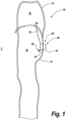
- FIG. 1 is a cross-sectional illustration of a protective suit 10 having a high-pressure passthrough 20, in accordance with a first exemplary embodiment of the present disclosure.
- the protective suit 10 may generally include a garment that is capable of protecting a human being from a harmful environment, commonly chemical environments where the human being would be exposed to chemicals which could injure or kill a human being. While the subject disclosure uses a chemically protective suit 10 as a primary example, it is noted that protective suits 10 used in other environments are also considered within the scope of the present disclosure.
- the protective suit 10 generally includes a body portion 12 with a head portion 14 connected to the body portion 12 with an airtight connection.
- the head portion 14 may be a full head apparatus, a facemask, or similar device which can provide the user with SCBA capabilities, such that the user can breathe air supplied from a compressed or filtered source, such as air tanks or air cylinders.
- the body portion 12 and head portion 14 may each have interior portions 16 which can be in fluid communication with one another or separated from one another. All portions of the protective suit 10 may be sealed against an outside atmosphere 2, including at the foot holes, wrist holes, or any other places.
- the protective suit 10 may be constructed from any materials conventionally used in the industry and may include any other features of conventional suits, including communication devices, hermetic closure devices, life-support devices, etc.
- the high-pressure passthrough 20 may generally refer to the apparatus which allows compressed breathing gas to be brought into the protective suit 10 and allows for a portion of the high-pressure gas to be passthrough into the interior portion 16 of the protective suit 10.
- the high-pressure passthrough 20 generally includes a penetrator body 30 connected to the protective suit 10.
- the penetrator body 30 includes a first half 32 or first part which is positioned exterior of the protective suit 10 and a second half 34 or second part which is positioned interior of the protective suit 10, i.e., inside the interior portion 16.
- a SCBA feed line 70 may be connected to the second half 34 by a quick connect to supply a quantity of breathing gas to the head portion 14.
- the quick connect may include an FD17 series high-pressure quick disconnect coupling device, for instance.
- a high-pressure passthrough valve 50 is positioned on the second half 34 and supplies a quantity of high-pressure breathing gas to the interior space 16 of the protective suit 10.
- the high-pressure breathing gas when released into the interior space 16, is a lower temperature than ambient air due to the high-pressurization of the breathing gas within cylinders.
- the infusion of the high-pressure gas into the interior space 16 acts to cool the interior space 16 due to the rapid decompression of the gas and provide for a more comfortable environment for the wearer of the protective suit 10.
- various protective suits and SCBAs used conventionally in the industry include the ability to convert high-pressure gas to a low pressure, but only in positions fully outside of the protective suit. These type of devices decrease the gas pressure from high to low prior to the gas moving through the passthrough.
- the subject disclosure allows for the transfer of high-pressure gas through the high-pressure passthrough 20, e.g., at a pressure above 6208.3 kPa (900 PSI), and once it is inside the protective suit 10, the high-pressure gas may be decreased to a low pressure as needed for an SCBA and cooling.
- FIG. 2 is a front view illustration of the protective suit 10 having the high-pressure passthrough 20, in accordance with the first exemplary embodiment of the present disclosure.
- the high-pressure passthrough 20 positioned on the protective suit 10 may be connected to any number of external cylinders 18 having a quantity of compressed breathing gas.
- the cylinders 18 may be connected to the high-pressure passthrough 20 with a high-pressure gas line 19 to supply the breathing gas to the high-pressure passthrough 20.
- the external cylinders 18 may be carried on a backpack of the wearer of the protective suit 10 (not shown). It is noted that the subject disclosure is specifically directed to using high-pressure which may be generally understood as gas that is significantly pressurized above atmospheric air pressure.
- pressure between 0-2068.4kPa (0-300 PSI) is generally understood as low pressure, whereas pressure above 2068.4kPa (300 PSI) may be viewed as high-pressure, which includes pressures on the lower end of the scale, e.g., 2068.4kPa to 6208.3kPA (300 PSI to 900 PSI) and pressures that are greater, e . g ., 6208.3kPA (900 PSI) to approximately 44815.8kPa (6,500 PSI).
- the pressure in which the apparatus 20 is intended to operate is above 6208.3kPA (900 PSI).
- the high-pressure gas has a pressurization of substantially between 6208.3kPA (900 PSI) and 44815.8kPa (6,500 PSI).
- FIG. 3 is an exploded schematic illustration of the high-pressure passthrough 20, in accordance with the first exemplary embodiment of the present disclosure.
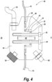
- FIG. 4 is a detailed, cross-sectional side view illustration of the high-pressure passthrough 20 in use with a protective suit 10, in accordance with the first exemplary embodiment of the present disclosure.
- the high-pressure passthrough 20, which may also be referred to herein as 'high-pressure passthrough apparatus 20' or 'apparatus 20' includes a penetrator body 30 connectable to a protective suit 10 ( FIG. 4 ), such as a chemical suit.
- the first half 32 and second half 34 of the penetrator body 30 may be durable structures capable of withstanding the harsh conditions to which the protective suit 10 may be exposed.
- the first and second halves 32, 34 are constructed from 7075 aluminum and may have a surface treatment positioned on one or more surfaces thereof.
- the surface treatment may include a hard coat anodizing and/or polytetrafluoroethylene (TEFLON ® ) flash-coating.
- a high-pressure inlet 60 which receives a quantity of high-pressure gas, such as from high-pressure gas cylinders, is positioned on a first side of the penetrator body 30, on the first half 32 ( FIG. 1 ).
- the first side of the penetrator body 30 may be the side that is positioned exterior of the protective suit 10 and that contacts the ambient atmosphere 2.
- a high-pressure self-contained breathing apparatus (SCBA) outlet 70 is connected to the penetrator body 30.
- a high-pressure passthrough valve 50 is also positioned on the second side (second half 34) of the penetrator body 30 such that it is positioned within the interior space 16 of the protective suit 10.
- the penetrator body 30 When the penetrator body 30 is positioned on the protective suit 10 with the first half 32 positioned on an exterior side and the second half 34 positioned on an interior side, the penetrator body 30 may be hermetically sealed to ensure that there is no air leak through the penetrator body 30 or between a connection of the penetrator body 30 with the protective suit 10.
- a hermetically sealed engagement may be provided between the first and second halves 32, 34 using a number of different structures.
- One of the first and second halves 32, 34 may include a raised boss 36 positioned on an interior edge of either the first or second half 32, 34 to provide exceptional sealing against the protective suit 10 material, as shown in FIG. 4 .
- a high-pressure sealing O-ring 38 and/or a secondary/environmental O-ring 40 may be positioned between the first and second halves 32, 34.
- the high-pressure O-ring 38 may maintain the high-pressure connection between the first and second halves 32, 34, while the secondary O-ring 40 may prevent infiltration of ambient atmosphere from gaining access to the interior of the penetrator body 30.
- the O-rings 38, 40 may be positioned proximate to a protrusion 35 of the second half 34 which fits within a cavity 33 of the first half 32.
- a number of threaded connectors 42 or fasteners may be used to secure the two halves 32, 34 together and to retain the O-rings 38, 40 in their proper positions.
- the threaded connectors 42 may be positioned through holes in the first half 32 and threadedly engage with threaded holes in the second half 34, the connection of which may be toleranced sufficiently to prevent air leakage.
- the penetrator body 30 may include appropriate ducting and gas flow structures 44 to allow high-pressure air introduced in the high-pressure inlet 60 to be passed from the first half 32 to the second half 34, and to the SCBA feed line 70 and the high-pressure passthrough valve 50.
- the ducting and gas flow structures 44 are schematically shown in FIG. 4 , but it is noted that structures beyond what are depicted would be used to properly convey the pressurized gas through the high-pressure passthrough 20.
- the high-pressure passthrough valve 50 may be capable of receiving the high-pressure gas from the high-pressure inlet 60 and releasing a portion of that high-pressure gas into the interior portion 16 of the protective suit 10. While the specifics of the high-pressure gas may vary, it is noted that the high-pressure passthrough valve 50 has a service pressure range of between 6208.3kPA (900 PSI) and 44815.8kPa (6,500 PSI).
- the ability to use the high-pressure gas already required for SCBA use with protective suits to cool the interior of the protective suit may significantly improve the use of protective suits.
- Other benefits may also include the ability to over pressurize or supply a positive pressure within the protective suit. Having a positive pressure within the protective suit may, for example, help prevent infiltration of chemicals within an inadvertent hole or puncture within the protective suit. In this example, the positive pressure may immediately create an airflow from the interior of the protective suit to the outside atmosphere through a hole or puncture, which may prevent chemicals from entering through the hole or puncture.
- FIG. 5 is an exploded schematic illustration of the high-pressure passthrough 120, in accordance with a second exemplary embodiment of the present disclosure.
- FIG. 6 is a detailed, cross-sectional side view illustration of the high-pressure passthrough 120 in use with a protective suit 10, in accordance with the second exemplary embodiment of the present disclosure.
- the second exemplary embodiment may be substantially similar to the first exemplary embodiment and may include any of the features disclosed relative to the first exemplary embodiment.
- the high-pressure passthrough 120 which may also be referred to herein as 'high-pressure passthrough apparatus 120' or 'apparatus 120' includes a penetrator body 130 connectable to a protective suit 10 ( FIG. 6 ), such as a chemical suit.
- the first half 132 and second half 134 of the penetrator body 130 may be durable structures capable of withstanding the harsh conditions to which the protective suit 10 may be exposed.
- the first and second halves 132, 134 are constructed from 7075 aluminum and may have a surface treatment positioned on one or more surfaces thereof.
- the surface treatment may include a hard coat anodizing and/or polytetrafluoroethylene (TEFLON ® ) flash-coating.
- a high-pressure inlet 160 which receives a quantity of high-pressure gas, such as from high-pressure gas cylinders, is positioned on a first side of the penetrator body 130, on the first half 132 ( FIG. 1 ).
- the first side of the penetrator body 130 may be the side that is positioned exterior of the protective suit 10 and that contacts the ambient atmosphere 2.
- a high-pressure passthrough valve 150 is also positioned on the second side (second half 134) of the penetrator body 130 such that it is positioned within the interior space 16 of the protective suit 10.
- the penetrator body 130 When the penetrator body 130 is positioned on the protective suit 10 with the first half 132 positioned on an exterior side and the second half 134 positioned on an interior side, the penetrator body 130 may be hermetically sealed to ensure that there is no air leak through the penetrator body 130 or between a connection of the penetrator body 130 with the protective suit 10.
- a hermetically sealed engagement may be provided between the first and second halves 132, 134 using a number of different structures.
- One of the first and second halves 132, 134 may include a raised boss 136 positioned on an interior edge of either the first or second half 132, 134 to provide exceptional sealing against the protective suit 10 material, as shown in FIG. 6 .
- a high-pressure sealing O-ring 138 and/or a secondary/environmental O-ring 140 may be positioned between the first and second halves 132, 134.
- the high-pressure O-ring 138 may maintain the high-pressure connection between the first and second halves 132, 134, while the secondary O-ring 140 may prevent infiltration of ambient atmosphere from gaining access to the interior of the penetrator body 130.
- the O-rings 138, 140 may be positioned proximate to a protrusion 135 of the second half 134 which fits within a cavity 133 of the first half 132.
- a number of threaded connectors 142 or fasteners may be used to secure the two halves 132, 134 together and to retain the O-rings 138, 140 in their proper positions.
- the threaded connectors 142 may be positioned through holes in the first half 132 and threadedly engage with threaded holes in the second half 134, the connection of which may be toleranced sufficiently to prevent air leakage.
- the penetrator body 130 may include appropriate ducting and gas flow structures 144 to allow high-pressure air introduced in the high-pressure inlet 160 to be passed from the first half 132 to the second half 134, and to the SCBA feed line 170 and the high-pressure passthrough valve 150.
- the ducting and gas flow structures 144 are schematically shown in FIG. 6 , but it is noted that structures beyond what are depicted would be used to properly convey the pressurized gas through the high-pressure passthrough 120.
- the apparatus 120 of FIGS. 5-6 may include an adapter block 180 which is positioned on the interior side 16 of the protective suit 10 and acts to redirect airflow from the second half 134.
- the adapter block 180 may be secured to the rear face of the second half 134 with threaded connectors 142.
- a belt clip 184 may be included to allow the apparatus 120 to clip to a belt worn by the user.
- the belt clip 184 may be connected to the adapter block 180 with a threaded connector 142.
- a hose barb fitting 190 may be connectable to the adapter block 180 to allow the high-pressure gas to be directed through cooling tubes (not shown) within a protective suit 10, which may be used with or in place of air cooling of the protective suit 10 as described relative to FIGS. 3-4 .
- the hose barb fitting 190 may include a barbed end to allow the end of a hose to easily connect to the apparatus 120.
- the high-pressure passthrough valve 150 and the adapter block 180 may be capable of receiving the high-pressure gas from the high-pressure inlet 160 and releasing a portion of that high-pressure gas into the interior portion 16 of the protective suit 10. After the high-pressure gas is moved through the ducting and gas flow structures 144 between the first and second halves 132, 134, it may be directed through additional ducting and gas flow structures, such as a cooling air passage 145 positioned between the second half 134 and the adapter block 180. While the specifics of the high-pressure gas may vary, it is noted that the high-pressure passthrough valve 150 has a service pressure range of between 6208.3kPA (900 PSI) and 44815.8kPa (6,500 PSI).
- the ability to use the high-pressure gas already required for SCBA use with protective suits to cool the interior of the protective suit may significantly improve the use of protective suits.
- Other benefits may also include the ability to over pressurize or supply a positive pressure within the protective suit. Having a positive pressure within the protective suit may, for example, help prevent infiltration of chemicals within an inadvertent hole or puncture within the protective suit. In this example, the positive pressure may immediately create an airflow from the interior of the protective suit to the outside atmosphere through a hole or puncture, which may prevent chemicals from entering through the hole or puncture.
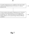
- FIG. 7 is a flowchart 200 illustrating a method of supplying a quantity of high-pressure air to an interior of a chemical protective suit, in accordance with a third exemplary embodiment of the disclosure.
- any process descriptions or blocks in flow charts should be understood as representing modules, segments, portions of code, or steps that include one or more instructions for implementing specific logical functions in the process, and alternate implementations are included within the scope of the present disclosure in which functions may be executed out of order from that shown or discussed, including substantially concurrently or in reverse order, depending on the functionality involved, as would be understood by those reasonably skilled in the art of the present disclosure.
- a quantity of high-pressure air is supplied to a first side of a high-pressure passthrough positioned on an exterior of a chemical protective suit. At least a portion of the quantity of high-pressure air is released to an interior of the chemical protective suit with a high-pressure passthrough valve, wherein the high-pressure passthrough valve further comprises a service pressure range of between 6208.3kPa (900 PSI) and 44815.8kPa (6,500 PSI) (block 204). It is noted that the method may include any number of additional steps, processes, or functions, including any disclosed relative to any other figure of this disclosure.
- At least a second portion of the quantity of high-pressure air may be released to the SCBA unit while the high-pressure gas is also released through the high-pressure passthrough valve.
- the use of high-pressure gas emitted through the passthrough valve may be used to cool the interior of the chemical protective suit. For example, it may also be used to provide a positive pressure within the protective suit.
Landscapes
- Health & Medical Sciences (AREA)
- General Health & Medical Sciences (AREA)
- Business, Economics & Management (AREA)
- Emergency Management (AREA)
- Toxicology (AREA)
- Respiratory Apparatuses And Protective Means (AREA)
- Pulmonology (AREA)
- Emergency Medicine (AREA)
Claims (9)
- Appareil de passage haute pression, comprenant :un corps de pénétrateur (30) pouvant être raccordé à une combinaison chimique (10) ayant une partie corps (12) et une partie tête (14), dans lequel le corps de pénétrateur (30) comprend une première moitié positionnable sur un côté extérieur de la combinaison chimique et une seconde moitié positionnable sur un côté intérieur de la combinaison chimique (10) lorsque le corps de pénétrateur (30) est raccordé à la combinaison chimique (10) ;une entrée haute pression (60) positionnée sur la première moitié du corps de pénétrateur (30) recevant un gaz haute pression provenant d'une source haute pression à une pression de service comprise entre 6208,3 kPA et 44815,9 kPA (900 PSI et 6500 PSI) ;une sortie (70) d'appareil respiratoire autonome haute pression (SCBA) positionnée sur la seconde moitié du corps de pénétrateur (30) recevant le gaz haute pression à ladite pression de service depuis l'entrée haute pression (60) et fournissant le gaz haute pression à la partie tête (14) de la combinaison chimique (10) ; etune valve de passage haute pression (50) positionnée sur la seconde moitié du corps de pénétrateur (30) à l'intérieur de la partie corps de la combinaison (10) et recevant le gaz haute pression à ladite pression de service en provenance de l'entrée haute pression (60), dans lequel le gaz haute pression est fourni à la partie corps de la combinaison chimique par l'intermédiaire de la valve de passage haute pression.
- Appareil de passage haute pression selon la revendication 1, comprenant également une mise en prise scellée hermétiquement entre les première et seconde moitiés, dans lequel la mise en prise scellée hermétiquement comprend un bossage surélevé (136) sur au moins l'une des première et seconde moitiés.
- Appareil de passage haute pression selon la revendication 1, comprenant également au moins un joint torique (138, 140) positionné entre les première et seconde moitiés.
- Appareil de passage haute pression selon la revendication 1, comprenant également au moins un raccord fileté mis en prise de manière amovible entre les première et seconde moitiés.
- Appareil de passage haute pression selon la revendication 1, dans lequel le corps de pénétrateur (30) comprend également un traitement de surface, le traitement de surface étant au moins l'un parmi :
une anodisation de revêtement dur ; et un revêtement éclair en polytétrafluoroéthylène. - Appareil de passage haute pression selon la revendication 1, dans lequel la valve de passage haute pression (50) libère une quantité d'air haute pression dans la partie corps de la combinaison chimique lorsque le corps de pénétrateur (30) est raccordé à la combinaison chimique.
- Procédé d'alimentation d'une quantité d'air haute pression à l'intérieur d'une combinaison de protection chimique comprenant une partie corps (12) et une partie tête (14), le procédé comprenant :la fourniture d'une quantité de gaz haute pression provenant d'une source haute pression, à une pression de service comprise entre 6208,3 kPA et 44815,9 kPA (900 PSI et 6500 PSI), à une entrée haute pression (60) positionnée sur une première moitié d'un corps de pénétrateur (30), la première moitié étant positionnée sur un extérieur de ladite combinaison de protection chimique (10) ;la réception de ladite quantité de gaz haute pression à ladite pression de service de ladite première moitié dudit corps de pénétrateur (30) au niveau d'une seconde moitié dudit corps de pénétrateur (30), la seconde moitié étant positionnée à l'intérieur de ladite combinaison de protection chimique (10) ;la libération d'au moins une première partie de la quantité de gaz haute pression à la pression de service vers une sortie (70) d'appareil respiratoire autonome (SCBA) positionnée sur ladite seconde moitié dudit corps de pénétrateur (30) alimentant ladite première partie vers la partie tête de la combinaison de protection chimique (10) ; etla libération d'au moins une seconde partie de la quantité de gaz à haute pression dans la partie corps de la combinaison de protection chimique (10) au moyen d'une valve de passage haute pression (50), dans lequel la valve de passage haute pression (50) est positionnée sur la seconde moitié du corps de pénétrateur (30) à l'intérieur de la partie corps de la combinaison (10).
- Procédé selon la revendication 7, dans lequel la libération de la partie de la quantité de gaz haute pression vers la partie corps de la combinaison de protection chimique (10) avec la valve de passage haute pression (50) refroidit l'intérieur de la combinaison de protection chimique (10).
- Procédé selon la revendication 7, dans lequel la quantité de gaz haute pression libérée sur la partie corps de la combinaison de protection chimique (10) avec la valve de passage haute pression (50) comprend également une quantité de gaz comprimé au-dessus de la pression atmosphérique de l'air.
Applications Claiming Priority (2)
| Application Number | Priority Date | Filing Date | Title |
|---|---|---|---|
| US15/098,981 US10307622B2 (en) | 2016-04-14 | 2016-04-14 | High-pressure passthrough for protective suit |
| PCT/US2017/026272 WO2017180414A1 (fr) | 2016-04-14 | 2017-04-06 | Passage haute pression pour combinaison de protection |
Publications (3)
| Publication Number | Publication Date |
|---|---|
| EP3442368A1 EP3442368A1 (fr) | 2019-02-20 |
| EP3442368A4 EP3442368A4 (fr) | 2019-11-13 |
| EP3442368B1 true EP3442368B1 (fr) | 2024-03-20 |
Family
ID=60039902
Family Applications (1)
| Application Number | Title | Priority Date | Filing Date |
|---|---|---|---|
| EP17782867.0A Active EP3442368B1 (fr) | 2016-04-14 | 2017-04-06 | Passage haute pression pour combinaison de protection |
Country Status (4)
| Country | Link |
|---|---|
| US (1) | US10307622B2 (fr) |
| EP (1) | EP3442368B1 (fr) |
| CA (1) | CA3021075C (fr) |
| WO (1) | WO2017180414A1 (fr) |
Families Citing this family (8)
| Publication number | Priority date | Publication date | Assignee | Title |
|---|---|---|---|---|
| US10941757B2 (en) * | 2018-08-20 | 2021-03-09 | Hamilton Sunstrand Corporation | Portable hydraulic cylinder for the recharge of water for extra-vehicular activity |
| USD939147S1 (en) * | 2020-02-14 | 2021-12-21 | Med-Eng, Llc | Bomb disposal suit |
| CN111420318B (zh) * | 2020-03-18 | 2021-11-23 | 浙安集团有限公司 | 一种消防救援用防阻水滞水的水冷空调服 |
| US20210330999A1 (en) * | 2020-04-24 | 2021-10-28 | Production Club Inc. | Sterile Body Suit Apparatus, System, and Method |
| US12599184B2 (en) * | 2021-01-06 | 2026-04-14 | Unitech Services Group, Inc. | Personal protective equipment ensemble made up of a launderable hood and an air dispersion protective face shield assembly |
| US20220212040A1 (en) * | 2021-01-06 | 2022-07-07 | Unitech Services Group, Inc. | Personal protective equipment ensemble made up of a launderable hood and an air dispersion protective headgear |
| CN114794618B (zh) * | 2022-05-13 | 2025-06-13 | 中国人民解放军中部战区总医院 | 可降温式医用防护服及其降温智能控制方法、拆卸方法 |
| PL441829A1 (pl) * | 2022-07-22 | 2024-01-29 | Sławomir Ścibiorek | Kombinezon ochronny |
Citations (1)
| Publication number | Priority date | Publication date | Assignee | Title |
|---|---|---|---|---|
| EP1007157B1 (fr) * | 1998-04-15 | 2004-12-01 | Spiromec AB | Unite de valve pour vetement de protection integrale |
Family Cites Families (25)
| Publication number | Priority date | Publication date | Assignee | Title |
|---|---|---|---|---|
| US3064448A (en) | 1960-03-15 | 1962-11-20 | Paul E Whittington | Air conditioned fuel handling suit |
| GB929897A (en) | 1961-02-11 | 1963-06-26 | Spembly Ltd | Air filter attachments for pressure ventilated suits |
| US5127896A (en) | 1989-09-05 | 1992-07-07 | Mcdonnell Douglas Corporation | Anthropomorphic tank suit |
| US5014355A (en) * | 1989-09-29 | 1991-05-14 | Technical Innovations, Inc. | Disposable environmental control suit |
| DE3941684C1 (fr) * | 1989-12-18 | 1991-07-18 | Dornier Luftfahrt Gmbh, 8031 Wessling, De | |
| US5293864A (en) * | 1991-08-01 | 1994-03-15 | Geomet Technologies, Inc. | Emergency breathing apparatus |
| US5355875A (en) | 1992-10-06 | 1994-10-18 | Vinatronics Division | Protective garment using one-way valves |
| US5421326A (en) * | 1993-04-19 | 1995-06-06 | H.R.I. Incorporated | Heat resistant suit with active cooling system |
| US6076571A (en) * | 1998-05-05 | 2000-06-20 | Burns; Keith Douglas | Passthrough assemblies for a chemical protective suit |
| AUPQ664400A0 (en) | 2000-04-03 | 2000-05-04 | Safety Equipment Australia Pty Ltd | Ventilation system for protective suit |
| US7875011B2 (en) | 2002-02-26 | 2011-01-25 | Harvie Mark R | Cooling, heating, bladder relief, gas, hydration and nutrition chem-bio suit connectivity system |
| US6948191B2 (en) | 2002-04-12 | 2005-09-27 | 3M Innovative Properties Company | Personal protective suit with partial flow restriction |
| US6796304B2 (en) * | 2002-04-12 | 2004-09-28 | 3M Innovative Properties Company | Personal containment system with sealed passthrough |
| US20040237178A1 (en) | 2003-05-27 | 2004-12-02 | Gaspar Landeros | Self-contained on land on water in air protective apparatus for mass protection and mass continuation |
| US7647927B2 (en) * | 2003-08-22 | 2010-01-19 | Wilcox Industries Corp. | Self-contained breathing system |
| US20050062284A1 (en) | 2003-08-25 | 2005-03-24 | Juergen Schreiner | Pressure relief valve in connector assembly of inflatable articles |
| US20060175337A1 (en) * | 2003-09-30 | 2006-08-10 | Defosset Josh P | Complex-shape compressed gas reservoirs |
| US7748380B1 (en) | 2004-04-06 | 2010-07-06 | Sti Licensing Corporation | Combined air-supplying/air-purifying system |
| US20060096593A1 (en) | 2004-11-11 | 2006-05-11 | Grilliot William L | Protective garment equipped to maintain positive gas pressure in space between protective garment and inner clothes worn by wearer |
| US7832396B2 (en) | 2005-06-10 | 2010-11-16 | Radium Incorporated | High air flow powered air purifying anti-contamination device |
| US7310999B2 (en) | 2005-09-16 | 2007-12-25 | Greg Miller | Body volume measurement apparatus and method of measuring the body volume of a person |
| DE102008019513B3 (de) | 2008-04-18 | 2009-08-27 | Dräger Safety AG & Co. KGaA | Schutzanzug mit Verdunstungskühler |
| US20100199405A1 (en) | 2009-02-07 | 2010-08-12 | Robert Albin Nelson | Blo-warm vest |
| US9155920B1 (en) | 2011-10-27 | 2015-10-13 | Flight Suits | Pass-through device for environmental protection suit |
| US9000913B2 (en) | 2013-01-02 | 2015-04-07 | Honeywell International Inc. | Wearable low pressure warning device with audio and visual indication |
-
2016
- 2016-04-14 US US15/098,981 patent/US10307622B2/en active Active
-
2017
- 2017-04-06 EP EP17782867.0A patent/EP3442368B1/fr active Active
- 2017-04-06 CA CA3021075A patent/CA3021075C/fr active Active
- 2017-04-06 WO PCT/US2017/026272 patent/WO2017180414A1/fr not_active Ceased
Patent Citations (1)
| Publication number | Priority date | Publication date | Assignee | Title |
|---|---|---|---|---|
| EP1007157B1 (fr) * | 1998-04-15 | 2004-12-01 | Spiromec AB | Unite de valve pour vetement de protection integrale |
Also Published As
| Publication number | Publication date |
|---|---|
| US20170296848A1 (en) | 2017-10-19 |
| EP3442368A4 (fr) | 2019-11-13 |
| CA3021075C (fr) | 2022-11-08 |
| US10307622B2 (en) | 2019-06-04 |
| WO2017180414A1 (fr) | 2017-10-19 |
| CA3021075A1 (fr) | 2017-10-19 |
| EP3442368A1 (fr) | 2019-02-20 |
Similar Documents
| Publication | Publication Date | Title |
|---|---|---|
| EP3442368B1 (fr) | Passage haute pression pour combinaison de protection | |
| US4458680A (en) | Protective supplied breathing air garment | |
| US20140190476A1 (en) | Seal for full face mask | |
| US20160001111A1 (en) | Reconfigurable Full Facemask having a Cartridge Module for Respiratory Protection | |
| US5027807A (en) | Protective garment cooling device | |
| EP1501606B1 (fr) | Ensemble respirateur | |
| US10441826B2 (en) | Airflow control valve | |
| EP1773457B1 (fr) | Ensemble de protection vestimentaire | |
| US20140366873A1 (en) | Hybrid self-rescue equipment | |
| US20120017895A1 (en) | Respirator kit and contoured plenum therefor | |
| EP0883420B1 (fr) | Conduite d'alimentation pour equipement respiratoire | |
| EP3520862A1 (fr) | Appareil de tuyau d'eau et de gaz respirable | |
| US5492108A (en) | Ventilation system for protective garments | |
| US6688309B2 (en) | Breathing apparatus and method therefor | |
| US20220395710A1 (en) | Negative Pressure Respirator Assembly | |
| GB2430159A (en) | Breathing apparatus with inflatable harness | |
| US20250144452A1 (en) | Dual gasket for use with face masks | |
| US20070113846A1 (en) | Facepiece for a respirator for high performance fixed-wing aircraft crew protection | |
| US20230116265A1 (en) | Pressure reducer and self-contained breathing apparatus | |
| US20220401763A1 (en) | Dual gasket for use with face masks | |
| US20140338670A1 (en) | Positive Pressure Adapter | |
| US20250375628A1 (en) | Configurable Demand Regulator | |
| US20240226616A1 (en) | Respirator | |
| US20230330448A1 (en) | De-misting system for a mask and associated methods | |
| KR102651183B1 (ko) | 소방용 공기 호흡기 |
Legal Events
| Date | Code | Title | Description |
|---|---|---|---|
| STAA | Information on the status of an ep patent application or granted ep patent |
Free format text: STATUS: THE INTERNATIONAL PUBLICATION HAS BEEN MADE |
|
| PUAI | Public reference made under article 153(3) epc to a published international application that has entered the european phase |
Free format text: ORIGINAL CODE: 0009012 |
|
| STAA | Information on the status of an ep patent application or granted ep patent |
Free format text: STATUS: REQUEST FOR EXAMINATION WAS MADE |
|
| 17P | Request for examination filed |
Effective date: 20181016 |
|
| AK | Designated contracting states |
Kind code of ref document: A1 Designated state(s): AL AT BE BG CH CY CZ DE DK EE ES FI FR GB GR HR HU IE IS IT LI LT LU LV MC MK MT NL NO PL PT RO RS SE SI SK SM TR |
|
| AX | Request for extension of the european patent |
Extension state: BA ME |
|
| DAV | Request for validation of the european patent (deleted) | ||
| DAX | Request for extension of the european patent (deleted) | ||
| A4 | Supplementary search report drawn up and despatched |
Effective date: 20191015 |
|
| RIC1 | Information provided on ipc code assigned before grant |
Ipc: A41D 13/005 20060101AFI20191009BHEP |
|
| STAA | Information on the status of an ep patent application or granted ep patent |
Free format text: STATUS: EXAMINATION IS IN PROGRESS |
|
| 17Q | First examination report despatched |
Effective date: 20210506 |
|
| GRAP | Despatch of communication of intention to grant a patent |
Free format text: ORIGINAL CODE: EPIDOSNIGR1 |
|
| STAA | Information on the status of an ep patent application or granted ep patent |
Free format text: STATUS: GRANT OF PATENT IS INTENDED |
|
| INTG | Intention to grant announced |
Effective date: 20231023 |
|
| GRAS | Grant fee paid |
Free format text: ORIGINAL CODE: EPIDOSNIGR3 |
|
| GRAA | (expected) grant |
Free format text: ORIGINAL CODE: 0009210 |
|
| STAA | Information on the status of an ep patent application or granted ep patent |
Free format text: STATUS: THE PATENT HAS BEEN GRANTED |
|
| AK | Designated contracting states |
Kind code of ref document: B1 Designated state(s): AL AT BE BG CH CY CZ DE DK EE ES FI FR GB GR HR HU IE IS IT LI LT LU LV MC MK MT NL NO PL PT RO RS SE SI SK SM TR |
|
| REG | Reference to a national code |
Ref country code: GB Ref legal event code: FG4D |
|
| REG | Reference to a national code |
Ref country code: CH Ref legal event code: EP |
|
| REG | Reference to a national code |
Ref country code: DE Ref legal event code: R096 Ref document number: 602017080218 Country of ref document: DE |
|
| REG | Reference to a national code |
Ref country code: IE Ref legal event code: FG4D |
|
| PG25 | Lapsed in a contracting state [announced via postgrant information from national office to epo] |
Ref country code: LT Free format text: LAPSE BECAUSE OF FAILURE TO SUBMIT A TRANSLATION OF THE DESCRIPTION OR TO PAY THE FEE WITHIN THE PRESCRIBED TIME-LIMIT Effective date: 20240320 |
|
| REG | Reference to a national code |
Ref country code: LT Ref legal event code: MG9D |
|
| PG25 | Lapsed in a contracting state [announced via postgrant information from national office to epo] |
Ref country code: GR Free format text: LAPSE BECAUSE OF FAILURE TO SUBMIT A TRANSLATION OF THE DESCRIPTION OR TO PAY THE FEE WITHIN THE PRESCRIBED TIME-LIMIT Effective date: 20240621 |
|
| PG25 | Lapsed in a contracting state [announced via postgrant information from national office to epo] |
Ref country code: HR Free format text: LAPSE BECAUSE OF FAILURE TO SUBMIT A TRANSLATION OF THE DESCRIPTION OR TO PAY THE FEE WITHIN THE PRESCRIBED TIME-LIMIT Effective date: 20240320 Ref country code: RS Free format text: LAPSE BECAUSE OF FAILURE TO SUBMIT A TRANSLATION OF THE DESCRIPTION OR TO PAY THE FEE WITHIN THE PRESCRIBED TIME-LIMIT Effective date: 20240620 |
|
| REG | Reference to a national code |
Ref country code: NL Ref legal event code: MP Effective date: 20240320 |
|
| PG25 | Lapsed in a contracting state [announced via postgrant information from national office to epo] |
Ref country code: RS Free format text: LAPSE BECAUSE OF FAILURE TO SUBMIT A TRANSLATION OF THE DESCRIPTION OR TO PAY THE FEE WITHIN THE PRESCRIBED TIME-LIMIT Effective date: 20240620 Ref country code: NO Free format text: LAPSE BECAUSE OF FAILURE TO SUBMIT A TRANSLATION OF THE DESCRIPTION OR TO PAY THE FEE WITHIN THE PRESCRIBED TIME-LIMIT Effective date: 20240620 Ref country code: LT Free format text: LAPSE BECAUSE OF FAILURE TO SUBMIT A TRANSLATION OF THE DESCRIPTION OR TO PAY THE FEE WITHIN THE PRESCRIBED TIME-LIMIT Effective date: 20240320 Ref country code: HR Free format text: LAPSE BECAUSE OF FAILURE TO SUBMIT A TRANSLATION OF THE DESCRIPTION OR TO PAY THE FEE WITHIN THE PRESCRIBED TIME-LIMIT Effective date: 20240320 Ref country code: GR Free format text: LAPSE BECAUSE OF FAILURE TO SUBMIT A TRANSLATION OF THE DESCRIPTION OR TO PAY THE FEE WITHIN THE PRESCRIBED TIME-LIMIT Effective date: 20240621 Ref country code: FI Free format text: LAPSE BECAUSE OF FAILURE TO SUBMIT A TRANSLATION OF THE DESCRIPTION OR TO PAY THE FEE WITHIN THE PRESCRIBED TIME-LIMIT Effective date: 20240320 Ref country code: BG Free format text: LAPSE BECAUSE OF FAILURE TO SUBMIT A TRANSLATION OF THE DESCRIPTION OR TO PAY THE FEE WITHIN THE PRESCRIBED TIME-LIMIT Effective date: 20240320 |
|
| REG | Reference to a national code |
Ref country code: AT Ref legal event code: MK05 Ref document number: 1667006 Country of ref document: AT Kind code of ref document: T Effective date: 20240320 |
|
| PG25 | Lapsed in a contracting state [announced via postgrant information from national office to epo] |
Ref country code: SE Free format text: LAPSE BECAUSE OF FAILURE TO SUBMIT A TRANSLATION OF THE DESCRIPTION OR TO PAY THE FEE WITHIN THE PRESCRIBED TIME-LIMIT Effective date: 20240320 Ref country code: LV Free format text: LAPSE BECAUSE OF FAILURE TO SUBMIT A TRANSLATION OF THE DESCRIPTION OR TO PAY THE FEE WITHIN THE PRESCRIBED TIME-LIMIT Effective date: 20240320 |
|
| PG25 | Lapsed in a contracting state [announced via postgrant information from national office to epo] |
Ref country code: NL Free format text: LAPSE BECAUSE OF FAILURE TO SUBMIT A TRANSLATION OF THE DESCRIPTION OR TO PAY THE FEE WITHIN THE PRESCRIBED TIME-LIMIT Effective date: 20240320 |
|
| PG25 | Lapsed in a contracting state [announced via postgrant information from national office to epo] |
Ref country code: NL Free format text: LAPSE BECAUSE OF FAILURE TO SUBMIT A TRANSLATION OF THE DESCRIPTION OR TO PAY THE FEE WITHIN THE PRESCRIBED TIME-LIMIT Effective date: 20240320 |
|
| PG25 | Lapsed in a contracting state [announced via postgrant information from national office to epo] |
Ref country code: IS Free format text: LAPSE BECAUSE OF FAILURE TO SUBMIT A TRANSLATION OF THE DESCRIPTION OR TO PAY THE FEE WITHIN THE PRESCRIBED TIME-LIMIT Effective date: 20240720 |
|
| PG25 | Lapsed in a contracting state [announced via postgrant information from national office to epo] |
Ref country code: PT Free format text: LAPSE BECAUSE OF FAILURE TO SUBMIT A TRANSLATION OF THE DESCRIPTION OR TO PAY THE FEE WITHIN THE PRESCRIBED TIME-LIMIT Effective date: 20240722 Ref country code: SM Free format text: LAPSE BECAUSE OF FAILURE TO SUBMIT A TRANSLATION OF THE DESCRIPTION OR TO PAY THE FEE WITHIN THE PRESCRIBED TIME-LIMIT Effective date: 20240320 |
|
| PG25 | Lapsed in a contracting state [announced via postgrant information from national office to epo] |
Ref country code: ES Free format text: LAPSE BECAUSE OF FAILURE TO SUBMIT A TRANSLATION OF THE DESCRIPTION OR TO PAY THE FEE WITHIN THE PRESCRIBED TIME-LIMIT Effective date: 20240320 |
|
| PG25 | Lapsed in a contracting state [announced via postgrant information from national office to epo] |
Ref country code: CZ Free format text: LAPSE BECAUSE OF FAILURE TO SUBMIT A TRANSLATION OF THE DESCRIPTION OR TO PAY THE FEE WITHIN THE PRESCRIBED TIME-LIMIT Effective date: 20240320 Ref country code: EE Free format text: LAPSE BECAUSE OF FAILURE TO SUBMIT A TRANSLATION OF THE DESCRIPTION OR TO PAY THE FEE WITHIN THE PRESCRIBED TIME-LIMIT Effective date: 20240320 |
|
| PG25 | Lapsed in a contracting state [announced via postgrant information from national office to epo] |
Ref country code: AT Free format text: LAPSE BECAUSE OF FAILURE TO SUBMIT A TRANSLATION OF THE DESCRIPTION OR TO PAY THE FEE WITHIN THE PRESCRIBED TIME-LIMIT Effective date: 20240320 |
|
| PG25 | Lapsed in a contracting state [announced via postgrant information from national office to epo] |
Ref country code: PL Free format text: LAPSE BECAUSE OF FAILURE TO SUBMIT A TRANSLATION OF THE DESCRIPTION OR TO PAY THE FEE WITHIN THE PRESCRIBED TIME-LIMIT Effective date: 20240320 |
|
| PG25 | Lapsed in a contracting state [announced via postgrant information from national office to epo] |
Ref country code: SK Free format text: LAPSE BECAUSE OF FAILURE TO SUBMIT A TRANSLATION OF THE DESCRIPTION OR TO PAY THE FEE WITHIN THE PRESCRIBED TIME-LIMIT Effective date: 20240320 |
|
| PG25 | Lapsed in a contracting state [announced via postgrant information from national office to epo] |
Ref country code: SM Free format text: LAPSE BECAUSE OF FAILURE TO SUBMIT A TRANSLATION OF THE DESCRIPTION OR TO PAY THE FEE WITHIN THE PRESCRIBED TIME-LIMIT Effective date: 20240320 Ref country code: SK Free format text: LAPSE BECAUSE OF FAILURE TO SUBMIT A TRANSLATION OF THE DESCRIPTION OR TO PAY THE FEE WITHIN THE PRESCRIBED TIME-LIMIT Effective date: 20240320 Ref country code: RO Free format text: LAPSE BECAUSE OF FAILURE TO SUBMIT A TRANSLATION OF THE DESCRIPTION OR TO PAY THE FEE WITHIN THE PRESCRIBED TIME-LIMIT Effective date: 20240320 Ref country code: PT Free format text: LAPSE BECAUSE OF FAILURE TO SUBMIT A TRANSLATION OF THE DESCRIPTION OR TO PAY THE FEE WITHIN THE PRESCRIBED TIME-LIMIT Effective date: 20240722 Ref country code: PL Free format text: LAPSE BECAUSE OF FAILURE TO SUBMIT A TRANSLATION OF THE DESCRIPTION OR TO PAY THE FEE WITHIN THE PRESCRIBED TIME-LIMIT Effective date: 20240320 Ref country code: IS Free format text: LAPSE BECAUSE OF FAILURE TO SUBMIT A TRANSLATION OF THE DESCRIPTION OR TO PAY THE FEE WITHIN THE PRESCRIBED TIME-LIMIT Effective date: 20240720 Ref country code: ES Free format text: LAPSE BECAUSE OF FAILURE TO SUBMIT A TRANSLATION OF THE DESCRIPTION OR TO PAY THE FEE WITHIN THE PRESCRIBED TIME-LIMIT Effective date: 20240320 Ref country code: EE Free format text: LAPSE BECAUSE OF FAILURE TO SUBMIT A TRANSLATION OF THE DESCRIPTION OR TO PAY THE FEE WITHIN THE PRESCRIBED TIME-LIMIT Effective date: 20240320 Ref country code: CZ Free format text: LAPSE BECAUSE OF FAILURE TO SUBMIT A TRANSLATION OF THE DESCRIPTION OR TO PAY THE FEE WITHIN THE PRESCRIBED TIME-LIMIT Effective date: 20240320 Ref country code: AT Free format text: LAPSE BECAUSE OF FAILURE TO SUBMIT A TRANSLATION OF THE DESCRIPTION OR TO PAY THE FEE WITHIN THE PRESCRIBED TIME-LIMIT Effective date: 20240320 |
|
| REG | Reference to a national code |
Ref country code: DE Ref legal event code: R119 Ref document number: 602017080218 Country of ref document: DE |
|
| REG | Reference to a national code |
Ref country code: CH Ref legal event code: PL |
|
| PG25 | Lapsed in a contracting state [announced via postgrant information from national office to epo] |
Ref country code: IT Free format text: LAPSE BECAUSE OF FAILURE TO SUBMIT A TRANSLATION OF THE DESCRIPTION OR TO PAY THE FEE WITHIN THE PRESCRIBED TIME-LIMIT Effective date: 20240320 |
|
| PG25 | Lapsed in a contracting state [announced via postgrant information from national office to epo] |
Ref country code: LU Free format text: LAPSE BECAUSE OF NON-PAYMENT OF DUE FEES Effective date: 20240406 |
|
| REG | Reference to a national code |
Ref country code: BE Ref legal event code: MM Effective date: 20240430 |
|
| PG25 | Lapsed in a contracting state [announced via postgrant information from national office to epo] |
Ref country code: LU Free format text: LAPSE BECAUSE OF NON-PAYMENT OF DUE FEES Effective date: 20240406 Ref country code: IT Free format text: LAPSE BECAUSE OF FAILURE TO SUBMIT A TRANSLATION OF THE DESCRIPTION OR TO PAY THE FEE WITHIN THE PRESCRIBED TIME-LIMIT Effective date: 20240320 |
|
| PG25 | Lapsed in a contracting state [announced via postgrant information from national office to epo] |
Ref country code: MC Free format text: LAPSE BECAUSE OF FAILURE TO SUBMIT A TRANSLATION OF THE DESCRIPTION OR TO PAY THE FEE WITHIN THE PRESCRIBED TIME-LIMIT Effective date: 20240320 |
|
| PG25 | Lapsed in a contracting state [announced via postgrant information from national office to epo] |
Ref country code: DE Free format text: LAPSE BECAUSE OF NON-PAYMENT OF DUE FEES Effective date: 20241105 |
|
| PG25 | Lapsed in a contracting state [announced via postgrant information from national office to epo] |
Ref country code: DK Free format text: LAPSE BECAUSE OF FAILURE TO SUBMIT A TRANSLATION OF THE DESCRIPTION OR TO PAY THE FEE WITHIN THE PRESCRIBED TIME-LIMIT Effective date: 20240320 |
|
| PG25 | Lapsed in a contracting state [announced via postgrant information from national office to epo] |
Ref country code: BE Free format text: LAPSE BECAUSE OF NON-PAYMENT OF DUE FEES Effective date: 20240430 |
|
| PLBE | No opposition filed within time limit |
Free format text: ORIGINAL CODE: 0009261 |
|
| STAA | Information on the status of an ep patent application or granted ep patent |
Free format text: STATUS: NO OPPOSITION FILED WITHIN TIME LIMIT |
|
| PG25 | Lapsed in a contracting state [announced via postgrant information from national office to epo] |
Ref country code: MC Free format text: LAPSE BECAUSE OF FAILURE TO SUBMIT A TRANSLATION OF THE DESCRIPTION OR TO PAY THE FEE WITHIN THE PRESCRIBED TIME-LIMIT Effective date: 20240320 Ref country code: DK Free format text: LAPSE BECAUSE OF FAILURE TO SUBMIT A TRANSLATION OF THE DESCRIPTION OR TO PAY THE FEE WITHIN THE PRESCRIBED TIME-LIMIT Effective date: 20240320 Ref country code: DE Free format text: LAPSE BECAUSE OF NON-PAYMENT OF DUE FEES Effective date: 20241105 Ref country code: BE Free format text: LAPSE BECAUSE OF NON-PAYMENT OF DUE FEES Effective date: 20240430 Ref country code: CH Free format text: LAPSE BECAUSE OF NON-PAYMENT OF DUE FEES Effective date: 20240430 |
|
| 26N | No opposition filed |
Effective date: 20241223 |
|
| GBPC | Gb: european patent ceased through non-payment of renewal fee |
Effective date: 20240620 |
|
| PG25 | Lapsed in a contracting state [announced via postgrant information from national office to epo] |
Ref country code: IE Free format text: LAPSE BECAUSE OF NON-PAYMENT OF DUE FEES Effective date: 20240406 |
|
| PG25 | Lapsed in a contracting state [announced via postgrant information from national office to epo] |
Ref country code: SI Free format text: LAPSE BECAUSE OF FAILURE TO SUBMIT A TRANSLATION OF THE DESCRIPTION OR TO PAY THE FEE WITHIN THE PRESCRIBED TIME-LIMIT Effective date: 20240320 |
|
| PG25 | Lapsed in a contracting state [announced via postgrant information from national office to epo] |
Ref country code: FR Free format text: LAPSE BECAUSE OF NON-PAYMENT OF DUE FEES Effective date: 20240520 |
|
| PG25 | Lapsed in a contracting state [announced via postgrant information from national office to epo] |
Ref country code: GB Free format text: LAPSE BECAUSE OF NON-PAYMENT OF DUE FEES Effective date: 20240620 |
|
| PG25 | Lapsed in a contracting state [announced via postgrant information from national office to epo] |
Ref country code: CY Free format text: LAPSE BECAUSE OF FAILURE TO SUBMIT A TRANSLATION OF THE DESCRIPTION OR TO PAY THE FEE WITHIN THE PRESCRIBED TIME-LIMIT; INVALID AB INITIO Effective date: 20170406 |
|
| PG25 | Lapsed in a contracting state [announced via postgrant information from national office to epo] |
Ref country code: HU Free format text: LAPSE BECAUSE OF FAILURE TO SUBMIT A TRANSLATION OF THE DESCRIPTION OR TO PAY THE FEE WITHIN THE PRESCRIBED TIME-LIMIT; INVALID AB INITIO Effective date: 20170406 |
|
| PG25 | Lapsed in a contracting state [announced via postgrant information from national office to epo] |
Ref country code: TR Free format text: LAPSE BECAUSE OF FAILURE TO SUBMIT A TRANSLATION OF THE DESCRIPTION OR TO PAY THE FEE WITHIN THE PRESCRIBED TIME-LIMIT Effective date: 20240320 |