EP3442374B1 - Strebenloses regenschirmgestell zur unterstützung einer kappe - Google Patents
Strebenloses regenschirmgestell zur unterstützung einer kappe Download PDFInfo
- Publication number
- EP3442374B1 EP3442374B1 EP16715577.9A EP16715577A EP3442374B1 EP 3442374 B1 EP3442374 B1 EP 3442374B1 EP 16715577 A EP16715577 A EP 16715577A EP 3442374 B1 EP3442374 B1 EP 3442374B1
- Authority
- EP
- European Patent Office
- Prior art keywords
- ribs
- piston
- umbrella frame
- fluid
- pressure
- Prior art date
- Legal status (The legal status is an assumption and is not a legal conclusion. Google has not performed a legal analysis and makes no representation as to the accuracy of the status listed.)
- Active
Links
Images


Classifications
-
- A—HUMAN NECESSITIES
- A45—HAND OR TRAVELLING ARTICLES
- A45B—WALKING STICKS; UMBRELLAS; LADIES' OR LIKE FANS
- A45B25/00—Details of umbrellas
- A45B25/16—Automatic openers, e.g. frames with spring mechanisms
- A45B25/165—Automatic openers, e.g. frames with spring mechanisms with fluid or electric actuators
-
- F—MECHANICAL ENGINEERING; LIGHTING; HEATING; WEAPONS; BLASTING
- F16—ENGINEERING ELEMENTS AND UNITS; GENERAL MEASURES FOR PRODUCING AND MAINTAINING EFFECTIVE FUNCTIONING OF MACHINES OR INSTALLATIONS; THERMAL INSULATION IN GENERAL
- F16F—SPRINGS; SHOCK-ABSORBERS; MEANS FOR DAMPING VIBRATION
- F16F9/00—Springs, vibration-dampers, shock-absorbers, or similarly-constructed movement-dampers using a fluid or the equivalent as damping medium
- F16F9/02—Springs, vibration-dampers, shock-absorbers, or similarly-constructed movement-dampers using a fluid or the equivalent as damping medium using gas only or vacuum
- F16F9/0209—Telescopic
- F16F9/0218—Mono-tubular units
-
- F—MECHANICAL ENGINEERING; LIGHTING; HEATING; WEAPONS; BLASTING
- F16—ENGINEERING ELEMENTS AND UNITS; GENERAL MEASURES FOR PRODUCING AND MAINTAINING EFFECTIVE FUNCTIONING OF MACHINES OR INSTALLATIONS; THERMAL INSULATION IN GENERAL
- F16F—SPRINGS; SHOCK-ABSORBERS; MEANS FOR DAMPING VIBRATION
- F16F9/00—Springs, vibration-dampers, shock-absorbers, or similarly-constructed movement-dampers using a fluid or the equivalent as damping medium
- F16F9/32—Details
- F16F9/34—Special valve constructions; Shape or construction of throttling passages
- F16F9/346—Throttling passages in the form of slots arranged in cylinder walls
-
- A—HUMAN NECESSITIES
- A45—HAND OR TRAVELLING ARTICLES
- A45B—WALKING STICKS; UMBRELLAS; LADIES' OR LIKE FANS
- A45B19/00—Special folding or telescoping of umbrellas
- A45B2019/007—Special folding or telescoping of umbrellas without stretchers
-
- F—MECHANICAL ENGINEERING; LIGHTING; HEATING; WEAPONS; BLASTING
- F16—ENGINEERING ELEMENTS AND UNITS; GENERAL MEASURES FOR PRODUCING AND MAINTAINING EFFECTIVE FUNCTIONING OF MACHINES OR INSTALLATIONS; THERMAL INSULATION IN GENERAL
- F16F—SPRINGS; SHOCK-ABSORBERS; MEANS FOR DAMPING VIBRATION
- F16F9/00—Springs, vibration-dampers, shock-absorbers, or similarly-constructed movement-dampers using a fluid or the equivalent as damping medium
- F16F9/02—Springs, vibration-dampers, shock-absorbers, or similarly-constructed movement-dampers using a fluid or the equivalent as damping medium using gas only or vacuum
Definitions
- the present invention relates in general to an umbrella frame arranged for supporting a canopy particularly suited for recreational use and more in particular to a strutless umbrella frame.
- Traditional sunshade umbrellas are provided with a frame arranged for supporting a canopy, the frame of such umbrellas generally comprises a plurality of ribs each supported on a central post by at least one strut.
- a pulley mechanism is usually provided, which pulley is arranged for slidably moving a sleeve along the external surface of the central post.
- the sleeve may be arranged for being connected to the ribs by the struts, such that a movement of the sleeve along the central post causes the ribs to move in between a retracted position, in which position the umbrella is closed, and an expanded position, in which position the umbrella is open.
- US5711332 discloses a strutless umbrella that includes a central post, either an inner plunger or tube, a canopy assembly including ribs pivotally mounted on the upper end of the central post. Links connect the ribs to the inner plunger or tube. Movement of one of the ribs moves the plunger or tube, which moves the remaining ribs. A latch pin holds the umbrella in the open position.
- the opening and closing of the umbrella is affected by moving the plunger within the central post in response to a pivoting movement of at least one of the ribs.
- the speed in which the plunger is moving with the central post will be greatly affected not only by the manual force applied to the at least one rib but also by the weight of the umbrella itself.
- the weight acting on the plurality of ribs may cause the plunger to uncontrollably move in the open or closed position thereby risking damage to the umbrella and more importantly may pose a safety hazard for the person operating the umbrella.
- a strutless umbrella frame which is arranged for supporting a canopy.
- the umbrella frame is provided with a central post, which may be at least partially hollow, and a plurality of ribs pivotally mounted to the central post about a pivot axis. The plurality of ribs arranged for being retracted when the umbrella frame is in the closed position and for being extended when the umbrella frame is in the open position.
- the umbrella frame is further provided with an actuator mechanism disposed within the central post, which is arranged for operating the umbrella frame between the closed and open position.
- a connecting mechanism may be also provided for hingendly connecting each of the plurality of ribs to the actuator mechanism such that a force generated by the pivoting movement of the at least one of the ribs is transferred to the actuator mechanism.
- the actuator mechanism is provided with at least one air spring.
- the at least one air spring may be provided with a piston rod connected at one end to the connecting mechanism and to the other end on the outer surface of a piston.
- the piston is arranged for being reciprocably movable within a fluid tight cylinder barrel in response to an opening and a closing force applied by pivoting movement of at least one of the ribs.
- the piston being arranged for dividing the interior of the cylinder barrel into a first and a second fluid chambers.
- the cylinder barrel defines a first and a second pressure zone.
- the at least one spring is provided with a first fluid regulating means arranged for allowing fluid, such as gas or liquid, to flow between the first and second fluid chambers when the piston is positioned along the first pressure zone.
- the air spring is further provided with a second fluid regulating means arranged for allowing fluid to flow between the first and second fluid chambers, when the piston is positioned in the second pressure zone.
- the second fluid regulating means is arranged for being activated in response to the pressure in the first or second chamber reaching a predetermined threshold due to an external force applied on the piston by the pivoting movement of at least one of the ribs.
- the fluid tight cylinder may be filled at least partially with a fluid such as for example a liquid, preferably having a predetermined viscosity, or a gas or a combination of both, preferably a gas, such as nitrogen.
- the actuator mechanism is arranged for opening the umbrella, when the plurality of ribs are in the retracted position, in response to a predetermined opening force applied initially by the pivoting movement of at least one of ribs.
- the actuator mechanism is further arranged for closing the umbrella, when the plurality of ribs are in the extended position, in response to a predetermined closing force applied initially by the pivoting movement of the at least one of the ribs.
- the opening and closing of the umbrella can be effected in a more controlled and safe manner, which is irrespective of the dimensions or the weight of the umbrella.
- the closing or opening of the umbrella frame may be for example be affected by exerting only an initial manual force. The initial manual force may activate the second fluid regulating means, so as to allow fluid to flow between the first and second fluid chamber, when the piston is positioned in the second pressure zone.
- the forces holding the piston in the second pressure zone may be overcome, thereby allowing the piston to move towards the fist pressure zone at a predetermined speed.
- the speed, at which the piston is moved from the second pressure zone towards the first pressure zone is determined by the rate in which the fluid flows through the second fluid regulating means when activated.
- the fluid may be unrestricted flow around the piston at a predetermined rate, thereby causing the piston to move towards the extended position.
- the speed at which the piston moves along the first pressure zone is determined by the rate at which the fluid flows around the piston through the first fluid regulating means.
- the piston as it moves in the extended position along the first pressure zone may cause the plurality of ribs to retract or extend without the need for applying a continuous external force on the at least one rib.
- the piston is biased towards the extended position, due to forces acting on inside surface of the piston being applied over a greater surface area in comparison to the forces acting on the outside surface area of the piston to which the piston rod is connected. Therefore, when the piston is positioned in the first pressure zone the plurality of ribs are more biased towards a predetermined position, either retracted or extended depending on the configuration of the air spring. Therefore, when the piston is positioned along the first pressure zone, the actuator mechanism is arranged for automatically opening or closing the umbrella, i.e.
- the manual force required to open or close the umbrella is at least significantly reduced compared to the state of the art solutions.
- the actuator mechanism is arranged for automatically opening or closing the umbrella frame, depending on the configuration of the air spring, in response to the positioning of at least one of the ribs at a predetermined angle with respect to the central post.
- the predetermined angle may be between 10.0 and 50 degrees, preferably between 20 and 40 degrees, and more preferably between 25 and 30 degrees.
- the second fluid regulating means may be arranged for being activated in response to the positioning of at least one of the ribs at a predetermined angle with respect to the central post.
- the piston is positioned in the second pressure zone, either when the umbrella is closed or opened, by positioning the at least one rib at a predetermined angle, would cause an opening or closing force to be exerted on the piston.
- the force applied by the at least one rib would cause the pressure in the first or second chamber in the cylinder barrel to increase to a predetermined threshold, thereby causing the second fluid regulating means to be activated, resulting in the piston to move towards the first pressure zone.
- the at least one rib may need to be maintained in the predetermined angle for a period of time until the piston reaches the first pressure zone.
- the actuator mechanism is arranged for exerting a biasing force for biasing the plurality of ribs in the direction of the open or closed position depending on the orientation of the air spring.
- the first fluid regulating means may comprise a fluid bypass, which allows fluid, such as gas, to flow around the piston.
- the fluid bypass may be in the form of a groove extending longitudinally along the length of the first pressure zone defined in the cylinder barrel.
- the dimensions, preferably the depth, of the groove may be arranged to increase linearly along the length of the first pressure zone, and preferably towards the extended position of the piston.
- the dimensions of the groove may increase linearly towards the cylinder barrel head located at one end of the cylinder barrel, which cylinder barrel head is arranged for sealing one end of the cylinder and delimiting the extension of the piston.
- a fluid bypass which has dimensions that linearly increase along the first pressure zone, may allow for adjusting the speed at which the piston moves along the first pressure zone by varying the rate at which fluid flows around the piston as the piston moves along the first pressure zone. In this way, the speed at which the umbrella frame is moved towards the open or closed position may be controlled, so as to ensure that damage to the umbrella or risk of injury to the operator due to the unexpected opening or closing of the umbrella is prevented.
- the second fluid regulating means is provided with at least one pressure activate valve.
- the pressure activated valve may be arranged being closed when the pressure in the first chamber is equal to the pressure in the second chamber, while it may be open so as to allow fluid to flow between the two chambers when the pressure in either the first or second chamber exceed a predetermined threshold.
- the second fluid regulating means may be provided with a first pressure activated valve, which may be arranged for being activated in response to the pressure in the first chamber reaching a predetermined threshold, and a second pressure activated valve arranged for being activated when the pressure in the second chamber reaches a predetermined threshold.
- the at least one pressure activated valve may be a one-way valve and, preferably comprises a spring.
- the connecting mechanism comprises a pivoting connection arranged for mounting the plurality of ribs to the top of the central post.
- the pivoting connections may be arranged for being retracted within the central post when the plurality of ribs are in the extended position.
- the connecting means may be provided with rigid connection means arranged for transferring the force applied by at least one of the ribs via the pivoting connections to the actuator mechanism, which may be disposed within the central post.
- the rigid connecting means may be provided in the form of a sleeve slidably movable within the central post by the pivoting action of at least one of the ribs.
- the actuator mechanism is positioned such that the cylinder barrel of the piston is towards the top of the central post. It has been found that by positioning the a cylinder barrel in this configuration, i.e. the upside down configuration, it is prevented that the piston comes in contact with the water when it rains, thereby significantly reducing the need for replacing the piston due to malfunctioning caused by the corrosion of the piston.
- the actuator mechanism may be provided with a plurality of air springs, each connected to the plurality of ribs via the connecting mechanism. It has been found that by providing a plurality of air springs, for example two air springs, the amount of manual effort and time required for opening and closing the umbrella greatly is reduced, while significantly improving the controlling of the operation.
- At least the central post is made from durable material, such as metal.
- the plurality of ribs are arranged for supporting a canopy, which may be arranged for providing protection against the sun and/or rain.
- top, bottom, over, under and the like in the description and the claims are used for descriptive purposes and not necessarily for describing relative positions. The terms so used are interchangeable under appropriate circumstances and the embodiments of the invention described herein can operate in other orientations than described or illustrated herein.
- Figures 1 and 2 show an example of a strutless umbrella frame positioned respectively in the open and closed positions.
- the strutless umbrella frame is provided with a plurality of ribs 10 to which a canopy may be attached connected to a central post 12.
- the central post may be made of a durable material, such as metal.
- the plurality of ribs 10 are pivotably connected to the central post 12 by means of connecting mechanism 13.
- the connecting mechanism 13 may be provided with pivoting connections 18 allowing the each of the plurality of ribs to pivot about a pivoting axis.
- the central post 12 may be provided as a single section, which is at least partially hollow, that is secured at one end to a base 11.
- the central post 12 may be provided with a plurality of sections, at least one of which may be hollow, that are interconnected to each other so as to form a single elongated structure suitable for supporting the plurality of ribs 10 and the canopy secured thereon.
- an actuating mechanism 14 may be positioned, which is arranged for operating the umbrella frame between the open and closed position by respectively extending and retracting the plurality of ribs 10.
- the actuating mechanism 14 is connected by the connecting mechanism 13 to the plurality of ribs 10 such that a pivoting movement of the at least one the ribs 10 causes the actuator mechanism 14 to actuate within the central post, thereby causing the remaining ribs to move in the direction of the pivoting movement the at least one rib 10.
- the actuator mechanism may be provided with at least one air spring, which may for example be positioned upside down within the central post 12, such that a biasing force exerted by the air spring is biasing the plurality of ribs in the extended position.
- the air spring may also be positioned such that the biasing force exerted by the air spring biases the plurality of ribs 10 in the retracted position or another position.
- the actuator mechanism may be provided with a plurality of air springs, each connected to the connecting mechanism and arranged for minimising the force required for closing or opening the umbrella.
- the air spring may be provided with a piston rod 21 arranged for being connected to the plurality of ribs 10 via the connecting mechanism 13, such that a force applied by at least one of the ribs 10 is transferred to the piston rod for reciprocating a piston 22 with a fluid tight cylinder barrel 20 in a desired direction.
- the connecting mechanism 13 may be provided with a top member 16 which is connected at one end to the plurality of ribs 10 via the pivoting connections 18 and connected at the other end to the piston rod 21 via rigid connection means, which connection means may be in the form of a sleeve slidably movable within the central post 12, rods, or any other type of suitable connection means known to the skilled person in the art.
- the top member 16 is secured to the top of the central post 12 by fixing member 17, which may comprise a plurality of screws arranged for cooperating with corresponding bores in the central post 12.
- the connecting mechanism 13 may be arranged when the umbrella is positioned at either the closed or open position, depending on the configuration of the air spring, for for being substantially retracted within the central post 12.
- the actuating mechanism may be provided with at least one air spring comprising a piston rod 21 connected at one end to the connecting mechanism 13 via the pivoting connection 18 and to the other end on the outer surface of a piston 22.
- the piston 22 may be arranged for dividing the interior of a fluid tight cylinder barrel 20 into a first fluid chamber 23a and a second fluid chamber 23b.
- the piston 22 being reciprocably movable within the cylinder barrel 20 in response to an opening and a closing force applied by pivoting movement of at least one of the ribs 10.
- the cylinder 20 being may be arranged for defining a first pressure zone 25a, wherein in the first pressure zone 25a fluid within the cylinder barrel 20 may be allowed to flow around the piston 22, and a second pressure zone 25b, wherein in the second pressure zone 25b the piston 22 may be sealingly connected to the internal surface of the cylinder barrel 20, which may prevent fluid to flow between the first and second chambers 23a and 23b.
- an external force acting on the piston rod 21, due to the pivoting movement of at least one of the ribs 10 may cause the pressure in the first chamber 23a to become higher or lower than the pressure in the second chamber 23b depending on the direction of the force acting on the piston 22.
- the piston 22, depending on the orientation of the air spring may be arranged for being positioned in the second pressure zone 25b, when the plurality of ribs 10 are in a more retracted position, and for being positioned in the first pressure zone 25a, when the plurality of ribs 10 are in a more open position.
- the piston 22 may be positioned in the first pressure zone 25a when the plurality of ribs are in a more retracted position, and for being positioned in the second pressure zone 25b, when the plurality of ribs 10 are in a more open or extended position.
- the air spring may further be provided with a first fluid regulating means arranged for allowing fluid, such as gas or liquid, to unrestricted flow between the first and second fluid chambers 23a and 23b when the piston 22 may be positioned along the first pressure zone 25a.
- the first fluid regulating means may be in the form of a fluid bypass, such as a groove, which extends along the first pressure zone 25a.
- the groove may be provided with linearly increasing dimensions so as to regulate the amount of fluid flowing between the first and second chambers 23a and 23b as the piston moves along the first pressure zone 25a.
- the dimensions of the groove may increase as the piston 22 is moved towards the cylinder head 26, which is arranged for sealing one end of the cylinder barrel 20 and delimiting the extension of the piston.
- the air spring may be further provided with second fluid regulating means 24 arranged, when activated, for example by a sufficient elevated pressure in either the first or the second chamber 23a and 23b exceeding a predetermined threshold pressure, for allowing fluid to flow between the first and second fluid chambers 23a and 23b, when the piston 22 is positioned in the second pressure zone 25b, so as to allow the piston to move.
- the elevated pressure in the first or second chamber 23a and 23b may be caused due to an external force applied on the piston rod 21 when the piston 22 is positioned in the second pressure zone 25b.
- the second fluid regulating means 24 is in the form of at least one pressure activating valve that is arranged for being activated the pressure in the first or second chamber 23a and 23b exceeds a predetermined threshold, thereby allowing fluid to flow around the piston 22 when the piston 22 is positioned in the second pressure zone.
- the air spring is be-provided with at least a first pressure activated valve, which may be activated by the pressure in the second chamber reaching a predetermined threshold due to the compression of the fluid in the second chamber by the external force exerted on the piston rod 21, and a second pressure activated valve, which may be activated when the pressure in the first chamber 23a reaches a predetermined threshold due to an external force applied on the piston rod 21.
- the at least one pressure activated valve may be a one-way valve, and may preferably comprise a spring.
- the valve is activated by applying an opening force on the piston rod 21 by positioning at least one of the ribs at a predetermined angle with respect to the central post 12.
- the valve may comprise a spring that is arranged for activating the valve when at least one of the ribs 10 in positioned at a predetermined angle with respect to the central post 12.
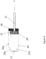
- FIG. 5 shows an air spring in the extended position, at which position the piston 22 is close to the cylinder head 26 and the plurality of ribs may be position, depending on the orientation of the air spring, in the extended position.
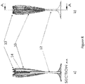
- the piston 22 In response to a closing force F applied at the piston rod 21, the piston 22 is moved along the first pressure zone 25a towards the retracted position, thereby causing the fluid to flow around the piston via the first fluid regulating means, as shown by the arrows in figure 6 .
- the piston 22 reaches the second pressure zone 25b, as shown in figure 7 , fluid is prevented from freely flowing between the first and second chamber 23a and 23b, because the piston 22 at the second pressure zone is for example sealingly connected to the internal surface of the cylinder 20.
- the closing force applied to the piston 22 would cause the compression of the fluid in the second chamber 23b, thereby increasing the pressure of the second chamber 23b.
- the second fluid regulating means 24 would cause the second fluid regulating means 24, thereby allowing fluid to flow around the piston and allowing the piston to be moved fully to the retracted position.
- the second regulating means would be deactivated, thereby preventing fluid to flow around the piston 22.
- the piston 22 would then be maintained in the second pressure zone 25b and is no longer biased outwardly.
- an opening force F may be exerted on the piston rod 21, which force causes the second regulating means 24 to be activated once a threshold pressure is surpassed in the first chamber 23a, thereby allowing fluid to flow from the first chamber 23a to the second chamber 23b.
- This allows the piston 22 to be moved towards the first pressure zone 25, at which zone fluid flows around the piston 22 thereby causing the pressure in the two chambers to equalise and biasing the piston outwardly, preferably even without having to apply an additional force to the ribs.
- the air spring may be arranged for opening the umbrella, when the plurality of ribs 10 are in the retracted position, in response to a predetermined opening force applied initially by the pivoting movement of at least one of ribs 10.
- the air spring may arranged for closing the umbrella, when the plurality of ribs 10 are in the extended position, in response to a predetermined closing force applied initially by the pivoting movement of the at least one of the ribs 10, so as to move the plurality of ribs 10 in the retracted position.
- the umbrella frame may be operated between the closed and open position in response to a pivoting movement of at least one ribs.
- Figures 8 to 11 show an example of an umbrella frame being operated from a closed position to the open position.
- the plurality of ribs 10 are retracted to a position close to the central tube 12.
- the plurality of ribs 10 may be maintained in the retracted position by the air spring.
- the plurality of ribs 10 may be maintained in the retracted position by positioning the piston 22 in the second pressure zone 25b.
- the opening of the umbrella frame may affected in response to a predetermined opening force being applied initially by the pivoting movement of at least one of ribs 10, so as to move the plurality of ribs in the extended position, by activating the second fluid regulating means 24 so as to move the piston 22 towards the first pressure zone 25a.
- a predetermined opening force being applied initially by the pivoting movement of at least one of ribs 10, so as to move the plurality of ribs in the extended position, by activating the second fluid regulating means 24 so as to move the piston 22 towards the first pressure zone 25a.
- the piston 22 would then be biased towards the extended position, thereby causing the plurality of ribs to move towards the extended position, without the need for continuously applying an opening force.
- the force acting on the inside surface of the piston 28 becomes preferably greater than force acting on the outside surface 27, causes the piston 22 to continuously move from the retracted position to the extended position.
- a predetermined opening force may be applied to the piston rod 21 thereby causing the piston 22 to move towards the extended position as the biasing force acting on the inside of the piston becomes larger than the force exerted on the outside of the piston.
- the piston would automatically move, and without the need for manual intervention, to the retracted position, thereby moving the remaining of the plurality of ribs in the extended position, as shown in figures 6 to 8 .
- the predetermined angle at which the automatic opening of the umbrella may be affected may be between 10.0 and 50 degrees, preferably between 20 and 40 degrees, and more preferably between 25 and 30 degrees or any other desirable position.
- the closing of the umbrella frame may be affected by applying a predetermined closing force to the piston 22 by pivotally moving at least one of the ribs 10 towards the retracted position, wherein force should be greater than the biasing force of the piston. Due to the continuous closing force applied by at least one of the ribs, the piston 22 would be move from the first pressure zone 25a to the second pressure zone 25b. At this position, the piston 22 would cause the pressure in the second chamber to increase to the predetermine threshold level, thereby causing the second fluid regulating means 24 to be activated so as to allow fluid to move around the piston.
- the second fluid regulating means 24 would be deactivated thereby locking the piston 22 in the second pressure zone 25b.
- the piston 22 would be maintained in the second pressure zone 25b until for example a predetermined opening force is applied by at least one of the ribs 10 so that for example the second fluid regulating means are activated, due to the pressure in the first chamber 23a reaching a predetermined threshold, allowing the piston to be moved again from the second pressure zone 25b to the first pressure zone 25b.
Landscapes
- Engineering & Computer Science (AREA)
- General Engineering & Computer Science (AREA)
- Mechanical Engineering (AREA)
- Walking Sticks, Umbrellas, And Fans (AREA)
Claims (14)
- Ein strebenloses Regenschirmgestell, angeordnet, um eine Kappe zu unterstützen, wobei das strebenlose Regenschirmgestell zwischen einer geschlossenen und einer offenen Position bedienbar ist, wobei das Regenschirmgestell Folgendes umfasst:einen zentralen Ständer (12);eine Vielzahl von Rippen (10), die jeweils schwenkbar um eine Schwenkachse am zentralen Ständer (12) montiert sind, wobei die Vielzahl von Rippen (10) angeordnet sind, um eingezogen zu sein, wenn das Regenschirmgestell in der geschlossenen Position ist, und um ausgestreckt zu sein, wenn das Regenschirmgestell in der offenen Position ist;einen Betätigungsmechanismus (14) angebracht innerhalb des zentralen Ständers (12), angeordnet, um das Regenschirmgestell zwischen der geschlossenen und der offenen Position zu bedienen; undeinen Verbindungsmechanismus (13), angeordnet, um jede der Vielzahl von Rippen (10) gelenkig mit dem Betätigungsmechanismus (14) zu verbinden, sodass eine Kraft, die durch die Schwenkbewegung von zumindest einer der Rippen (10) erzeugt wird, auf den Betätigungsmechanismus (14) übertragen wird;dadurch gekennzeichnet, dass der Betätigungsmechanismus (14) Folgendes umfasst:zumindest eine Luftfeder, welche eine Kolbenstange (21) umfasst, verbunden an einem Ende mit dem Verbindungsmechanismus (13) und am anderen Ende mit der Außenfläche (28) eines Kolbens (22), wobei der Kolben (22) innerhalb eines flüssigkeitsdichten Zylindermantels (20) in Reaktion auf eine Öffnungs- und eine Schließkraft, welche durch eine Schwenkbewegung von zumindest einer der Rippen (10) angewendet wird, wechselseitig beweglich ist, wobei der Kolben (22) angeordnet ist, um das Innere des Zylindermantels (20) in eine erste und eine zweite Flüssigkeitskammer (23a, 23b) zu teilen, worin der Zylindermantel (20) eine erste und eine zweite Druckzone (25a, 25b) definiert;ein erstes flüssigkeitsregulierendes Mittel, angeordnet, um es Flüssigkeit zu erlauben, zwischen der ersten und der zweiten Flüssigkeitskammer (23a, 23b) zu strömen, wenn der Kolben (22) entlang der ersten Druckzone (25a) positioniert ist; undein zweites flüssigkeitsregulierendes Mittel, angeordnet (24), um es Flüssigkeit zu erlauben, zwischen der ersten und der zweiten Flüssigkeitskammer (23a, 23b) zu strömen, wenn der Kolben (22) in der zweiten Druckzone (25b) positioniert ist, wobei das zweite flüssigkeitsregulierende Mittel (24) zumindest ein druckbetätigtes Ventil umfasst und angeordnet ist, um in Reaktion auf den Druck in der ersten oder zweiten Kammer aktiviert zu werden, die aufgrund einer externen Kraft, die durch die Schwenkbewegung von zumindest einer der Rippen (10) auf den Kolben (22) ausgeübt wird, eine vorgegebene Schwelle erreicht;wobei der Betätigungsmechanismus (14) angeordnet ist:a) zum Öffnen des Regenschirms, wenn die Vielzahl von Rippen (10) in der eingezogenen Position sind, in Reaktion auf eine vorgegebene Öffnungs kraft, die anfänglich durch die Schwenkbewegung von zumindest einer der Rippen (10) ausgeübt wird, undb) zum Schließen des Regenschirms, wenn die Vielzahl von Rippen (10) in der ausgestreckten Position sind, in Reaktion auf eine vorgegebene Schließkraft, die anfänglich durch die Schwenkbewegung von zumindest einer der Rippen (10) ausgeübt wird.
- Ein Regenschirmgestell nach Anspruch 1, wobei der Kolben (22) angeordnet ist, um in der zweiten Druckzone (25b) positioniert zu werden, wenn die Vielzahl von Rippen (10) in der eingezogenen Position sind, und um in der ersten Druckzone (25a) positioniert zu werden, wenn die Vielzahl der Rippen in der offenen Position sind.
- Ein Regenschirmgestell nach Anspruch 1 oder 2, wobei das zweite flüssigkeitsregulierende Mittel (24) angeordnet ist, um in Reaktion auf die Positionierung von zumindest einer der Rippen (10) in einem vorgegebenen Winkel in Bezug zum zentralen Ständer (12) aktiviert zu werden.
- Ein Regenschirmgestell nach Anspruch 3, wobei der vorgegebene Winkel zwischen 10,0 und 50 Grad beträgt, bevorzugt zwischen 20 und 40 Grad, und noch besser zwischen 25 und 30 Grad.
- Ein Regenschirmgestell nach irgendeinem der vorigen Ansprüche, wobei der Betätigungsmechanismus (14) angeordnet ist, um, wenn der Kolben (22) in der ersten Druckzone (25a) positioniert ist, eine Vorspannkraft zum Vorspannen der Vielzahl von Rippen (10) in die Richtung der offenen Position auszuüben.
- Ein Regenschirmgestell nach irgendeinem der vorigen Ansprüche, wobei das erste flüssigkeitsregulierende Mittel eine Flüssigkeitsumgehung umfasst, die es der Flüssigkeit erlaubt, zwischen der ersten und der zweiten Kammer (23a, 23b) zu strömen.
- Ein Regenschirmgestell nach Anspruch 6, wobei die Flüssigkeitsumgehung die Form einer Nut hat, die sich entlang der Länge der ersten Druckzone im Zylindermantel (20) ausstreckt.
- Ein Regenschirmgestell nach Anspruch 7, wobei die Abmessungen, bevorzugt die Tiefe, der Nut entlang der Länge der ersten Druckzone linear zunehmen.
- Ein Regenschirmgestell nach Anspruch 1, wobei das zweite flüssigkeitsregulierende Mittel ein erstes druckbetätigtes Ventil umfasst, angeordnet, um in Reaktion auf den Druck in der ersten Kammer, der eine vorgegebene Schwelle erreicht, betätigt zu werden, und ein zweites druckbetätigtes Ventil, angeordnet, um betätigt zu werden, wenn der Druck in der zweiten Kammer eine vorgegebene Schwelle erreicht.
- Ein Regenschirmgestell nach Anspruch 1 oder 9, wobei das zumindest eine druckbetätigte Ventil ein Einwegventil ist und bevorzugt eine Feder umfasst.
- Ein Regenschirmgestell nach irgendeinem der vorigen Ansprüche, wobei der Betätigungsmechanismus (14) so positioniert ist, dass der Zylindermantel (20) des Kolbens zur Spitze des zentralen Ständers hin liegt.
- Ein Regenschirmgestell nach irgendeinem der vorigen Ansprüche, wobei der zentrale Ständer (12) aus Metall hergestellt ist.
- Ein Regenschirmgestell nach irgendeinem der vorigen Ansprüche, wobei die Vielzahl von Rippen (10) angeordnet sind, um eine Kappe zu tragen.
- Ein Regenschirm, welcher ein Regenschirmgestell nach irgendeinem der Ansprüche 1 bis 13 umfasst, wobei die Vielzahl von Rippen (10) eine Kappe tragen.
Applications Claiming Priority (1)
| Application Number | Priority Date | Filing Date | Title |
|---|---|---|---|
| PCT/EP2016/058038 WO2017178042A1 (en) | 2016-04-12 | 2016-04-12 | A strutless umbrella frame for supporting a canopy |
Publications (2)
| Publication Number | Publication Date |
|---|---|
| EP3442374A1 EP3442374A1 (de) | 2019-02-20 |
| EP3442374B1 true EP3442374B1 (de) | 2021-06-09 |
Family
ID=55702007
Family Applications (1)
| Application Number | Title | Priority Date | Filing Date |
|---|---|---|---|
| EP16715577.9A Active EP3442374B1 (de) | 2016-04-12 | 2016-04-12 | Strebenloses regenschirmgestell zur unterstützung einer kappe |
Country Status (3)
| Country | Link |
|---|---|
| US (1) | US10813427B2 (de) |
| EP (1) | EP3442374B1 (de) |
| WO (1) | WO2017178042A1 (de) |
Families Citing this family (3)
| Publication number | Priority date | Publication date | Assignee | Title |
|---|---|---|---|---|
| CN113602509B (zh) * | 2021-08-30 | 2023-10-10 | 航宇救生装备有限公司 | 加油软管接头稳定伞骨架连接结构 |
| USD988453S1 (en) * | 2022-12-09 | 2023-06-06 | Zhejiang Kedi Leisure Products Co., Ltd | Top support structure of tent frame |
| CN117084489A (zh) * | 2023-08-29 | 2023-11-21 | 浙江永强集团股份有限公司 | 一种无短伞骨开合的电动直杆伞 |
Citations (1)
| Publication number | Priority date | Publication date | Assignee | Title |
|---|---|---|---|---|
| US4433759A (en) * | 1980-09-11 | 1984-02-28 | Nissan Motor Co. Ltd. | Gas spring |
Family Cites Families (20)
| Publication number | Priority date | Publication date | Assignee | Title |
|---|---|---|---|---|
| DE1809697A1 (de) * | 1968-11-19 | 1970-09-10 | Volkswagenwerk Ag | Fahrzeugfederung |
| FR2088644A5 (de) * | 1970-04-20 | 1972-01-07 | Peugeot & Renault | |
| JPS51774Y2 (de) * | 1971-02-26 | 1976-01-10 | ||
| DE2513302C2 (de) * | 1975-03-26 | 1985-05-30 | Stabilus Gmbh, 5400 Koblenz | Blockierbare pneumatische oder hydropneumatische Feder |
| JPS60234142A (ja) * | 1984-05-04 | 1985-11-20 | Honda Motor Co Ltd | 回動体のダンパ装置 |
| GB8511370D0 (en) * | 1985-05-03 | 1985-06-12 | Robertson M S | Garden/sun umbrellas |
| US4747422A (en) * | 1987-05-07 | 1988-05-31 | Chung Ching Horng | Pneumatic umbrella |
| JPH09158967A (ja) * | 1995-12-06 | 1997-06-17 | Showa:Kk | ガススプリング |
| DE19548139C2 (de) * | 1995-12-21 | 1998-09-24 | Stabilus Gmbh | Gasfeder mit einstellbarer Endposition |
| US5711332A (en) | 1996-01-26 | 1998-01-27 | American Holtzkraft, Inc. | Strutless umbrella |
| JPH10252800A (ja) * | 1997-01-07 | 1998-09-22 | Showa:Kk | ガススプリング |
| JPH10252801A (ja) * | 1997-01-07 | 1998-09-22 | Showa:Kk | ガススプリング |
| US6092632A (en) * | 1997-10-01 | 2000-07-25 | Fichtel And Sachs Industries, Inc. | Gas spring with temperature compensation |
| EP1229809B1 (de) * | 1999-11-17 | 2004-02-11 | Powerbrella CC | Vorrichtung für einen regenschirm |
| DE10302870B3 (de) * | 2003-01-28 | 2004-08-05 | Stabilus Gmbh | Verstellvorrichtung |
| US20050016803A1 (en) * | 2003-07-25 | 2005-01-27 | Chad Brummitt | Multiple stop gas spring for vehicle closure |
| DE102004026356B4 (de) * | 2004-05-26 | 2008-07-31 | Stabilus Gmbh | Zugfederanordnung |
| US20100244340A1 (en) * | 2008-03-19 | 2010-09-30 | Wootten Dennis K | Methods and apparatus for combined variable damping and variable spring rate suspension |
| JP2015010650A (ja) * | 2013-06-28 | 2015-01-19 | 株式会社大林組 | オイルダンパー、及び、ダンパーシステム |
| JP6514608B2 (ja) * | 2015-09-02 | 2019-05-15 | Kyb株式会社 | 緩衝装置 |
-
2016
- 2016-04-12 US US16/093,614 patent/US10813427B2/en active Active
- 2016-04-12 WO PCT/EP2016/058038 patent/WO2017178042A1/en not_active Ceased
- 2016-04-12 EP EP16715577.9A patent/EP3442374B1/de active Active
Patent Citations (1)
| Publication number | Priority date | Publication date | Assignee | Title |
|---|---|---|---|---|
| US4433759A (en) * | 1980-09-11 | 1984-02-28 | Nissan Motor Co. Ltd. | Gas spring |
Also Published As
| Publication number | Publication date |
|---|---|
| US20190116948A1 (en) | 2019-04-25 |
| US10813427B2 (en) | 2020-10-27 |
| WO2017178042A1 (en) | 2017-10-19 |
| EP3442374A1 (de) | 2019-02-20 |
Similar Documents
| Publication | Publication Date | Title |
|---|---|---|
| EP3442374B1 (de) | Strebenloses regenschirmgestell zur unterstützung einer kappe | |
| EP1437298B1 (de) | Zusatzfederbein für ein Flugzeugfahrwerk bestehend aus einem Drehbalken, einem Hauptfederbein und einem Zusatzfederbein | |
| US4986357A (en) | Well tool having a variable area hydraulic actuator | |
| US4007752A (en) | Telescopic umbrella | |
| JP7279956B2 (ja) | 自動リフト装置 | |
| US2662712A (en) | Telescopic mast | |
| US3393883A (en) | Aircraft landing gear | |
| CA2581574A1 (en) | Adjustable bicycle seat assemblies and methods of use | |
| JP2012522679A (ja) | 特に航空機を対象とした固定銛及び1つのそのような銛を含有する固定システム | |
| US9994309B2 (en) | Aircraft landing gear pitch trimmer actuator with variable damping | |
| CA2772515C (en) | Hydraulic jar with multiple high pressure chambers | |
| US20150351505A1 (en) | Cantilevered umbrella | |
| CA1219512A (en) | Temperature compensator for pressure regulator | |
| CN104843091B (zh) | 前翻式车身的支撑装置和车辆 | |
| US20110303818A1 (en) | Lift strut with mechanical spring element | |
| GB2240714A (en) | Shortenable umbrella | |
| US3534659A (en) | Telescopic hoist | |
| CN105339681A (zh) | 用于控制飞机发动机机舱的千斤顶的方法、实施该方法的千斤顶式提升系统以及被如此装备的机舱 | |
| KR880010979A (ko) | 전방 랜딩기어 점프 스프러트 조립체 | |
| JP2007205567A (ja) | 双方向補助ガススプリングおよび引込みスプリングのアセンブリ | |
| EP3481247B1 (de) | Faltbarer gelenkiger arm | |
| KR200374288Y1 (ko) | 트랙터용 써레 | |
| KR102349889B1 (ko) | 수동 충격 스트럿 수축 액추에이터를 갖는 랜딩 기어 장치 | |
| JP2510311Y2 (ja) | 高所作業車のレベリング装置 | |
| CN120323310B (zh) | 一种用于沙土地作物的灌溉装置 |
Legal Events
| Date | Code | Title | Description |
|---|---|---|---|
| STAA | Information on the status of an ep patent application or granted ep patent |
Free format text: STATUS: UNKNOWN |
|
| STAA | Information on the status of an ep patent application or granted ep patent |
Free format text: STATUS: THE INTERNATIONAL PUBLICATION HAS BEEN MADE |
|
| PUAI | Public reference made under article 153(3) epc to a published international application that has entered the european phase |
Free format text: ORIGINAL CODE: 0009012 |
|
| STAA | Information on the status of an ep patent application or granted ep patent |
Free format text: STATUS: REQUEST FOR EXAMINATION WAS MADE |
|
| 17P | Request for examination filed |
Effective date: 20181112 |
|
| AK | Designated contracting states |
Kind code of ref document: A1 Designated state(s): AL AT BE BG CH CY CZ DE DK EE ES FI FR GB GR HR HU IE IS IT LI LT LU LV MC MK MT NL NO PL PT RO RS SE SI SK SM TR |
|
| AX | Request for extension of the european patent |
Extension state: BA ME |
|
| DAV | Request for validation of the european patent (deleted) | ||
| DAX | Request for extension of the european patent (deleted) | ||
| STAA | Information on the status of an ep patent application or granted ep patent |
Free format text: STATUS: EXAMINATION IS IN PROGRESS |
|
| 17Q | First examination report despatched |
Effective date: 20200204 |
|
| GRAP | Despatch of communication of intention to grant a patent |
Free format text: ORIGINAL CODE: EPIDOSNIGR1 |
|
| STAA | Information on the status of an ep patent application or granted ep patent |
Free format text: STATUS: GRANT OF PATENT IS INTENDED |
|
| INTG | Intention to grant announced |
Effective date: 20201104 |
|
| GRAJ | Information related to disapproval of communication of intention to grant by the applicant or resumption of examination proceedings by the epo deleted |
Free format text: ORIGINAL CODE: EPIDOSDIGR1 |
|
| STAA | Information on the status of an ep patent application or granted ep patent |
Free format text: STATUS: EXAMINATION IS IN PROGRESS |
|
| GRAS | Grant fee paid |
Free format text: ORIGINAL CODE: EPIDOSNIGR3 |
|
| STAA | Information on the status of an ep patent application or granted ep patent |
Free format text: STATUS: GRANT OF PATENT IS INTENDED |
|
| GRAP | Despatch of communication of intention to grant a patent |
Free format text: ORIGINAL CODE: EPIDOSNIGR1 |
|
| INTC | Intention to grant announced (deleted) | ||
| INTG | Intention to grant announced |
Effective date: 20210310 |
|
| GRAA | (expected) grant |
Free format text: ORIGINAL CODE: 0009210 |
|
| STAA | Information on the status of an ep patent application or granted ep patent |
Free format text: STATUS: THE PATENT HAS BEEN GRANTED |
|
| AK | Designated contracting states |
Kind code of ref document: B1 Designated state(s): AL AT BE BG CH CY CZ DE DK EE ES FI FR GB GR HR HU IE IS IT LI LT LU LV MC MK MT NL NO PL PT RO RS SE SI SK SM TR |
|
| REG | Reference to a national code |
Ref country code: GB Ref legal event code: FG4D |
|
| REG | Reference to a national code |
Ref country code: CH Ref legal event code: EP Ref country code: AT Ref legal event code: REF Ref document number: 1399764 Country of ref document: AT Kind code of ref document: T Effective date: 20210615 |
|
| REG | Reference to a national code |
Ref country code: DE Ref legal event code: R096 Ref document number: 602016059091 Country of ref document: DE |
|
| REG | Reference to a national code |
Ref country code: IE Ref legal event code: FG4D |
|
| REG | Reference to a national code |
Ref country code: NL Ref legal event code: FP |
|
| REG | Reference to a national code |
Ref country code: LT Ref legal event code: MG9D |
|
| PG25 | Lapsed in a contracting state [announced via postgrant information from national office to epo] |
Ref country code: HR Free format text: LAPSE BECAUSE OF FAILURE TO SUBMIT A TRANSLATION OF THE DESCRIPTION OR TO PAY THE FEE WITHIN THE PRESCRIBED TIME-LIMIT Effective date: 20210609 Ref country code: BG Free format text: LAPSE BECAUSE OF FAILURE TO SUBMIT A TRANSLATION OF THE DESCRIPTION OR TO PAY THE FEE WITHIN THE PRESCRIBED TIME-LIMIT Effective date: 20210909 Ref country code: FI Free format text: LAPSE BECAUSE OF FAILURE TO SUBMIT A TRANSLATION OF THE DESCRIPTION OR TO PAY THE FEE WITHIN THE PRESCRIBED TIME-LIMIT Effective date: 20210609 Ref country code: LT Free format text: LAPSE BECAUSE OF FAILURE TO SUBMIT A TRANSLATION OF THE DESCRIPTION OR TO PAY THE FEE WITHIN THE PRESCRIBED TIME-LIMIT Effective date: 20210609 |
|
| REG | Reference to a national code |
Ref country code: AT Ref legal event code: MK05 Ref document number: 1399764 Country of ref document: AT Kind code of ref document: T Effective date: 20210609 |
|
| PG25 | Lapsed in a contracting state [announced via postgrant information from national office to epo] |
Ref country code: GR Free format text: LAPSE BECAUSE OF FAILURE TO SUBMIT A TRANSLATION OF THE DESCRIPTION OR TO PAY THE FEE WITHIN THE PRESCRIBED TIME-LIMIT Effective date: 20210910 Ref country code: LV Free format text: LAPSE BECAUSE OF FAILURE TO SUBMIT A TRANSLATION OF THE DESCRIPTION OR TO PAY THE FEE WITHIN THE PRESCRIBED TIME-LIMIT Effective date: 20210609 Ref country code: RS Free format text: LAPSE BECAUSE OF FAILURE TO SUBMIT A TRANSLATION OF THE DESCRIPTION OR TO PAY THE FEE WITHIN THE PRESCRIBED TIME-LIMIT Effective date: 20210609 Ref country code: SE Free format text: LAPSE BECAUSE OF FAILURE TO SUBMIT A TRANSLATION OF THE DESCRIPTION OR TO PAY THE FEE WITHIN THE PRESCRIBED TIME-LIMIT Effective date: 20210609 Ref country code: NO Free format text: LAPSE BECAUSE OF FAILURE TO SUBMIT A TRANSLATION OF THE DESCRIPTION OR TO PAY THE FEE WITHIN THE PRESCRIBED TIME-LIMIT Effective date: 20210909 |
|
| PG25 | Lapsed in a contracting state [announced via postgrant information from national office to epo] |
Ref country code: SK Free format text: LAPSE BECAUSE OF FAILURE TO SUBMIT A TRANSLATION OF THE DESCRIPTION OR TO PAY THE FEE WITHIN THE PRESCRIBED TIME-LIMIT Effective date: 20210609 Ref country code: SM Free format text: LAPSE BECAUSE OF FAILURE TO SUBMIT A TRANSLATION OF THE DESCRIPTION OR TO PAY THE FEE WITHIN THE PRESCRIBED TIME-LIMIT Effective date: 20210609 Ref country code: CZ Free format text: LAPSE BECAUSE OF FAILURE TO SUBMIT A TRANSLATION OF THE DESCRIPTION OR TO PAY THE FEE WITHIN THE PRESCRIBED TIME-LIMIT Effective date: 20210609 Ref country code: EE Free format text: LAPSE BECAUSE OF FAILURE TO SUBMIT A TRANSLATION OF THE DESCRIPTION OR TO PAY THE FEE WITHIN THE PRESCRIBED TIME-LIMIT Effective date: 20210609 Ref country code: AT Free format text: LAPSE BECAUSE OF FAILURE TO SUBMIT A TRANSLATION OF THE DESCRIPTION OR TO PAY THE FEE WITHIN THE PRESCRIBED TIME-LIMIT Effective date: 20210609 Ref country code: ES Free format text: LAPSE BECAUSE OF FAILURE TO SUBMIT A TRANSLATION OF THE DESCRIPTION OR TO PAY THE FEE WITHIN THE PRESCRIBED TIME-LIMIT Effective date: 20210609 Ref country code: PT Free format text: LAPSE BECAUSE OF FAILURE TO SUBMIT A TRANSLATION OF THE DESCRIPTION OR TO PAY THE FEE WITHIN THE PRESCRIBED TIME-LIMIT Effective date: 20211011 Ref country code: RO Free format text: LAPSE BECAUSE OF FAILURE TO SUBMIT A TRANSLATION OF THE DESCRIPTION OR TO PAY THE FEE WITHIN THE PRESCRIBED TIME-LIMIT Effective date: 20210609 |
|
| PG25 | Lapsed in a contracting state [announced via postgrant information from national office to epo] |
Ref country code: PL Free format text: LAPSE BECAUSE OF FAILURE TO SUBMIT A TRANSLATION OF THE DESCRIPTION OR TO PAY THE FEE WITHIN THE PRESCRIBED TIME-LIMIT Effective date: 20210609 |
|
| REG | Reference to a national code |
Ref country code: DE Ref legal event code: R097 Ref document number: 602016059091 Country of ref document: DE |
|
| PLBE | No opposition filed within time limit |
Free format text: ORIGINAL CODE: 0009261 |
|
| STAA | Information on the status of an ep patent application or granted ep patent |
Free format text: STATUS: NO OPPOSITION FILED WITHIN TIME LIMIT |
|
| PG25 | Lapsed in a contracting state [announced via postgrant information from national office to epo] |
Ref country code: DK Free format text: LAPSE BECAUSE OF FAILURE TO SUBMIT A TRANSLATION OF THE DESCRIPTION OR TO PAY THE FEE WITHIN THE PRESCRIBED TIME-LIMIT Effective date: 20210609 |
|
| 26N | No opposition filed |
Effective date: 20220310 |
|
| PG25 | Lapsed in a contracting state [announced via postgrant information from national office to epo] |
Ref country code: AL Free format text: LAPSE BECAUSE OF FAILURE TO SUBMIT A TRANSLATION OF THE DESCRIPTION OR TO PAY THE FEE WITHIN THE PRESCRIBED TIME-LIMIT Effective date: 20210609 |
|
| PG25 | Lapsed in a contracting state [announced via postgrant information from national office to epo] |
Ref country code: IT Free format text: LAPSE BECAUSE OF FAILURE TO SUBMIT A TRANSLATION OF THE DESCRIPTION OR TO PAY THE FEE WITHIN THE PRESCRIBED TIME-LIMIT Effective date: 20210609 |
|
| PG25 | Lapsed in a contracting state [announced via postgrant information from national office to epo] |
Ref country code: MC Free format text: LAPSE BECAUSE OF FAILURE TO SUBMIT A TRANSLATION OF THE DESCRIPTION OR TO PAY THE FEE WITHIN THE PRESCRIBED TIME-LIMIT Effective date: 20210609 |
|
| PG25 | Lapsed in a contracting state [announced via postgrant information from national office to epo] |
Ref country code: IE Free format text: LAPSE BECAUSE OF NON-PAYMENT OF DUE FEES Effective date: 20220412 |
|
| P01 | Opt-out of the competence of the unified patent court (upc) registered |
Effective date: 20230314 |
|
| PG25 | Lapsed in a contracting state [announced via postgrant information from national office to epo] |
Ref country code: HU Free format text: LAPSE BECAUSE OF FAILURE TO SUBMIT A TRANSLATION OF THE DESCRIPTION OR TO PAY THE FEE WITHIN THE PRESCRIBED TIME-LIMIT; INVALID AB INITIO Effective date: 20160412 |
|
| PG25 | Lapsed in a contracting state [announced via postgrant information from national office to epo] |
Ref country code: MK Free format text: LAPSE BECAUSE OF FAILURE TO SUBMIT A TRANSLATION OF THE DESCRIPTION OR TO PAY THE FEE WITHIN THE PRESCRIBED TIME-LIMIT Effective date: 20210609 Ref country code: CY Free format text: LAPSE BECAUSE OF FAILURE TO SUBMIT A TRANSLATION OF THE DESCRIPTION OR TO PAY THE FEE WITHIN THE PRESCRIBED TIME-LIMIT Effective date: 20210609 |
|
| PG25 | Lapsed in a contracting state [announced via postgrant information from national office to epo] |
Ref country code: MT Free format text: LAPSE BECAUSE OF FAILURE TO SUBMIT A TRANSLATION OF THE DESCRIPTION OR TO PAY THE FEE WITHIN THE PRESCRIBED TIME-LIMIT Effective date: 20210609 |
|
| PGFP | Annual fee paid to national office [announced via postgrant information from national office to epo] |
Ref country code: LU Payment date: 20250424 Year of fee payment: 10 |
|
| PGFP | Annual fee paid to national office [announced via postgrant information from national office to epo] |
Ref country code: DE Payment date: 20250428 Year of fee payment: 10 |
|
| PGFP | Annual fee paid to national office [announced via postgrant information from national office to epo] |
Ref country code: CH Payment date: 20250501 Year of fee payment: 10 |
|
| PG25 | Lapsed in a contracting state [announced via postgrant information from national office to epo] |
Ref country code: TR Free format text: LAPSE BECAUSE OF FAILURE TO SUBMIT A TRANSLATION OF THE DESCRIPTION OR TO PAY THE FEE WITHIN THE PRESCRIBED TIME-LIMIT Effective date: 20210609 |
|
| PGFP | Annual fee paid to national office [announced via postgrant information from national office to epo] |
Ref country code: GB Payment date: 20260319 Year of fee payment: 11 |
|
| PGFP | Annual fee paid to national office [announced via postgrant information from national office to epo] |
Ref country code: BE Payment date: 20260312 Year of fee payment: 11 |
|
| PGFP | Annual fee paid to national office [announced via postgrant information from national office to epo] |
Ref country code: NL Payment date: 20260312 Year of fee payment: 11 |
|
| PGFP | Annual fee paid to national office [announced via postgrant information from national office to epo] |
Ref country code: FR Payment date: 20260312 Year of fee payment: 11 |