EP3442679B1 - Vakuumfilter - Google Patents
Vakuumfilter Download PDFInfo
- Publication number
- EP3442679B1 EP3442679B1 EP17721234.7A EP17721234A EP3442679B1 EP 3442679 B1 EP3442679 B1 EP 3442679B1 EP 17721234 A EP17721234 A EP 17721234A EP 3442679 B1 EP3442679 B1 EP 3442679B1
- Authority
- EP
- European Patent Office
- Prior art keywords
- filter
- filter media
- housing
- media
- upper housing
- Prior art date
- Legal status (The legal status is an assumption and is not a legal conclusion. Google has not performed a legal analysis and makes no representation as to the accuracy of the status listed.)
- Active
Links
Images


Classifications
-
- A—HUMAN NECESSITIES
- A47—FURNITURE; DOMESTIC ARTICLES OR APPLIANCES; COFFEE MILLS; SPICE MILLS; SUCTION CLEANERS IN GENERAL
- A47L—DOMESTIC WASHING OR CLEANING; SUCTION CLEANERS IN GENERAL
- A47L11/00—Machines for cleaning floors, carpets, furniture, walls, or wall coverings
- A47L11/40—Parts or details of machines not provided for in groups A47L11/02 - A47L11/38, or not restricted to one of these groups, e.g. handles, arrangements of switches, skirts, buffers, levers
- A47L11/4075—Handles; levers
-
- A—HUMAN NECESSITIES
- A47—FURNITURE; DOMESTIC ARTICLES OR APPLIANCES; COFFEE MILLS; SPICE MILLS; SUCTION CLEANERS IN GENERAL
- A47L—DOMESTIC WASHING OR CLEANING; SUCTION CLEANERS IN GENERAL
- A47L5/00—Structural features of suction cleaners
- A47L5/12—Structural features of suction cleaners with power-driven air-pumps or air-compressors, e.g. driven by motor vehicle engine vacuum
- A47L5/22—Structural features of suction cleaners with power-driven air-pumps or air-compressors, e.g. driven by motor vehicle engine vacuum with rotary fans
- A47L5/24—Hand-supported suction cleaners
-
- A—HUMAN NECESSITIES
- A47—FURNITURE; DOMESTIC ARTICLES OR APPLIANCES; COFFEE MILLS; SPICE MILLS; SUCTION CLEANERS IN GENERAL
- A47L—DOMESTIC WASHING OR CLEANING; SUCTION CLEANERS IN GENERAL
- A47L9/00—Details or accessories of suction cleaners, e.g. mechanical means for controlling the suction or for effecting pulsating action; Storing devices specially adapted to suction cleaners or parts thereof; Carrying-vehicles specially adapted for suction cleaners
- A47L9/10—Filters; Dust separators; Dust removal; Automatic exchange of filters
- A47L9/12—Dry filters
-
- A—HUMAN NECESSITIES
- A47—FURNITURE; DOMESTIC ARTICLES OR APPLIANCES; COFFEE MILLS; SPICE MILLS; SUCTION CLEANERS IN GENERAL
- A47L—DOMESTIC WASHING OR CLEANING; SUCTION CLEANERS IN GENERAL
- A47L9/00—Details or accessories of suction cleaners, e.g. mechanical means for controlling the suction or for effecting pulsating action; Storing devices specially adapted to suction cleaners or parts thereof; Carrying-vehicles specially adapted for suction cleaners
- A47L9/10—Filters; Dust separators; Dust removal; Automatic exchange of filters
- A47L9/14—Bags or the like; Rigid filtering receptacles; Attachment of, or closures for, bags or receptacles
- A47L9/1427—Means for mounting or attaching bags or filtering receptacles in suction cleaners; Adapters
- A47L9/1436—Connecting plates, e.g. collars, end closures
- A47L9/1445—Connecting plates, e.g. collars, end closures with closure means
- A47L9/1454—Self-sealing closures, e.g. valves
-
- A—HUMAN NECESSITIES
- A47—FURNITURE; DOMESTIC ARTICLES OR APPLIANCES; COFFEE MILLS; SPICE MILLS; SUCTION CLEANERS IN GENERAL
- A47L—DOMESTIC WASHING OR CLEANING; SUCTION CLEANERS IN GENERAL
- A47L9/00—Details or accessories of suction cleaners, e.g. mechanical means for controlling the suction or for effecting pulsating action; Storing devices specially adapted to suction cleaners or parts thereof; Carrying-vehicles specially adapted for suction cleaners
- A47L9/10—Filters; Dust separators; Dust removal; Automatic exchange of filters
- A47L9/14—Bags or the like; Rigid filtering receptacles; Attachment of, or closures for, bags or receptacles
- A47L9/1481—Means for removing bags in suction cleaners, e.g. ejecting means; Means for exchanging bags
-
- A—HUMAN NECESSITIES
- A47—FURNITURE; DOMESTIC ARTICLES OR APPLIANCES; COFFEE MILLS; SPICE MILLS; SUCTION CLEANERS IN GENERAL
- A47L—DOMESTIC WASHING OR CLEANING; SUCTION CLEANERS IN GENERAL
- A47L9/00—Details or accessories of suction cleaners, e.g. mechanical means for controlling the suction or for effecting pulsating action; Storing devices specially adapted to suction cleaners or parts thereof; Carrying-vehicles specially adapted for suction cleaners
- A47L9/10—Filters; Dust separators; Dust removal; Automatic exchange of filters
- A47L9/16—Arrangement or disposition of cyclones or other devices with centrifugal action
- A47L9/1683—Dust collecting chambers; Dust collecting receptacles
-
- A—HUMAN NECESSITIES
- A47—FURNITURE; DOMESTIC ARTICLES OR APPLIANCES; COFFEE MILLS; SPICE MILLS; SUCTION CLEANERS IN GENERAL
- A47L—DOMESTIC WASHING OR CLEANING; SUCTION CLEANERS IN GENERAL
- A47L9/00—Details or accessories of suction cleaners, e.g. mechanical means for controlling the suction or for effecting pulsating action; Storing devices specially adapted to suction cleaners or parts thereof; Carrying-vehicles specially adapted for suction cleaners
- A47L9/10—Filters; Dust separators; Dust removal; Automatic exchange of filters
- A47L9/19—Means for monitoring filtering operation
-
- A—HUMAN NECESSITIES
- A47—FURNITURE; DOMESTIC ARTICLES OR APPLIANCES; COFFEE MILLS; SPICE MILLS; SUCTION CLEANERS IN GENERAL
- A47L—DOMESTIC WASHING OR CLEANING; SUCTION CLEANERS IN GENERAL
- A47L9/00—Details or accessories of suction cleaners, e.g. mechanical means for controlling the suction or for effecting pulsating action; Storing devices specially adapted to suction cleaners or parts thereof; Carrying-vehicles specially adapted for suction cleaners
- A47L9/28—Installation of the electric equipment, e.g. adaptation or attachment to the suction cleaner; Controlling suction cleaners by electric means
- A47L9/2805—Parameters or conditions being sensed
- A47L9/281—Parameters or conditions being sensed the amount or condition of incoming dirt or dust
-
- A—HUMAN NECESSITIES
- A47—FURNITURE; DOMESTIC ARTICLES OR APPLIANCES; COFFEE MILLS; SPICE MILLS; SUCTION CLEANERS IN GENERAL
- A47L—DOMESTIC WASHING OR CLEANING; SUCTION CLEANERS IN GENERAL
- A47L9/00—Details or accessories of suction cleaners, e.g. mechanical means for controlling the suction or for effecting pulsating action; Storing devices specially adapted to suction cleaners or parts thereof; Carrying-vehicles specially adapted for suction cleaners
- A47L9/28—Installation of the electric equipment, e.g. adaptation or attachment to the suction cleaner; Controlling suction cleaners by electric means
- A47L9/2836—Installation of the electric equipment, e.g. adaptation or attachment to the suction cleaner; Controlling suction cleaners by electric means characterised by the parts which are controlled
- A47L9/2842—Suction motors or blowers
-
- A—HUMAN NECESSITIES
- A47—FURNITURE; DOMESTIC ARTICLES OR APPLIANCES; COFFEE MILLS; SPICE MILLS; SUCTION CLEANERS IN GENERAL
- A47L—DOMESTIC WASHING OR CLEANING; SUCTION CLEANERS IN GENERAL
- A47L9/00—Details or accessories of suction cleaners, e.g. mechanical means for controlling the suction or for effecting pulsating action; Storing devices specially adapted to suction cleaners or parts thereof; Carrying-vehicles specially adapted for suction cleaners
- A47L9/28—Installation of the electric equipment, e.g. adaptation or attachment to the suction cleaner; Controlling suction cleaners by electric means
- A47L9/2857—User input or output elements for control, e.g. buttons, switches or displays
-
- A—HUMAN NECESSITIES
- A47—FURNITURE; DOMESTIC ARTICLES OR APPLIANCES; COFFEE MILLS; SPICE MILLS; SUCTION CLEANERS IN GENERAL
- A47L—DOMESTIC WASHING OR CLEANING; SUCTION CLEANERS IN GENERAL
- A47L9/00—Details or accessories of suction cleaners, e.g. mechanical means for controlling the suction or for effecting pulsating action; Storing devices specially adapted to suction cleaners or parts thereof; Carrying-vehicles specially adapted for suction cleaners
- A47L9/28—Installation of the electric equipment, e.g. adaptation or attachment to the suction cleaner; Controlling suction cleaners by electric means
- A47L9/2868—Arrangements for power supply of vacuum cleaners or the accessories thereof
- A47L9/2884—Details of arrangements of batteries or their installation
-
- A—HUMAN NECESSITIES
- A47—FURNITURE; DOMESTIC ARTICLES OR APPLIANCES; COFFEE MILLS; SPICE MILLS; SUCTION CLEANERS IN GENERAL
- A47L—DOMESTIC WASHING OR CLEANING; SUCTION CLEANERS IN GENERAL
- A47L9/00—Details or accessories of suction cleaners, e.g. mechanical means for controlling the suction or for effecting pulsating action; Storing devices specially adapted to suction cleaners or parts thereof; Carrying-vehicles specially adapted for suction cleaners
- A47L9/32—Handles
- A47L9/322—Handles for hand-supported suction cleaners
-
- B—PERFORMING OPERATIONS; TRANSPORTING
- B01—PHYSICAL OR CHEMICAL PROCESSES OR APPARATUS IN GENERAL
- B01D—SEPARATION
- B01D46/00—Filters or filtering processes specially modified for separating dispersed particles from gases or vapours
- B01D46/0001—Making filtering elements
-
- B—PERFORMING OPERATIONS; TRANSPORTING
- B01—PHYSICAL OR CHEMICAL PROCESSES OR APPARATUS IN GENERAL
- B01D—SEPARATION
- B01D46/00—Filters or filtering processes specially modified for separating dispersed particles from gases or vapours
- B01D46/0002—Casings; Housings; Frame constructions
- B01D46/0005—Mounting of filtering elements within casings, housings or frames
-
- B—PERFORMING OPERATIONS; TRANSPORTING
- B01—PHYSICAL OR CHEMICAL PROCESSES OR APPARATUS IN GENERAL
- B01D—SEPARATION
- B01D46/00—Filters or filtering processes specially modified for separating dispersed particles from gases or vapours
- B01D46/0084—Filters or filtering processes specially modified for separating dispersed particles from gases or vapours provided with safety means
- B01D46/0089—Anti-return means
-
- B—PERFORMING OPERATIONS; TRANSPORTING
- B01—PHYSICAL OR CHEMICAL PROCESSES OR APPARATUS IN GENERAL
- B01D—SEPARATION
- B01D46/00—Filters or filtering processes specially modified for separating dispersed particles from gases or vapours
- B01D46/02—Particle separators, e.g. dust precipitators, having hollow filters made of flexible material
-
- B—PERFORMING OPERATIONS; TRANSPORTING
- B01—PHYSICAL OR CHEMICAL PROCESSES OR APPARATUS IN GENERAL
- B01D—SEPARATION
- B01D46/00—Filters or filtering processes specially modified for separating dispersed particles from gases or vapours
- B01D46/42—Auxiliary equipment or operation thereof
-
- B—PERFORMING OPERATIONS; TRANSPORTING
- B01—PHYSICAL OR CHEMICAL PROCESSES OR APPARATUS IN GENERAL
- B01D—SEPARATION
- B01D46/00—Filters or filtering processes specially modified for separating dispersed particles from gases or vapours
- B01D46/42—Auxiliary equipment or operation thereof
- B01D46/4227—Manipulating filters or filter elements, e.g. handles or extracting tools
-
- B—PERFORMING OPERATIONS; TRANSPORTING
- B01—PHYSICAL OR CHEMICAL PROCESSES OR APPARATUS IN GENERAL
- B01D—SEPARATION
- B01D46/00—Filters or filtering processes specially modified for separating dispersed particles from gases or vapours
- B01D46/42—Auxiliary equipment or operation thereof
- B01D46/4254—Allowing or improving visual supervision, e.g. lamps, transparent parts, windows
-
- B—PERFORMING OPERATIONS; TRANSPORTING
- B01—PHYSICAL OR CHEMICAL PROCESSES OR APPARATUS IN GENERAL
- B01D—SEPARATION
- B01D46/00—Filters or filtering processes specially modified for separating dispersed particles from gases or vapours
- B01D46/42—Auxiliary equipment or operation thereof
- B01D46/4272—Special valve constructions adapted to filters or filter elements
-
- B—PERFORMING OPERATIONS; TRANSPORTING
- B01—PHYSICAL OR CHEMICAL PROCESSES OR APPARATUS IN GENERAL
- B01D—SEPARATION
- B01D46/00—Filters or filtering processes specially modified for separating dispersed particles from gases or vapours
- B01D46/52—Particle separators, e.g. dust precipitators, using filters embodying folded corrugated or wound sheet material
- B01D46/521—Particle separators, e.g. dust precipitators, using filters embodying folded corrugated or wound sheet material using folded, pleated material
-
- B—PERFORMING OPERATIONS; TRANSPORTING
- B01—PHYSICAL OR CHEMICAL PROCESSES OR APPARATUS IN GENERAL
- B01D—SEPARATION
- B01D2275/00—Filter media structures for filters specially adapted for separating dispersed particles from gases or vapours
- B01D2275/20—Shape of filtering material
- B01D2275/203—Shapes flexible in their geometry, e.g. bendable, adjustable to a certain size
-
- B—PERFORMING OPERATIONS; TRANSPORTING
- B01—PHYSICAL OR CHEMICAL PROCESSES OR APPARATUS IN GENERAL
- B01D—SEPARATION
- B01D2279/00—Filters adapted for separating dispersed particles from gases or vapours specially modified for specific uses
- B01D2279/55—Filters adapted for separating dispersed particles from gases or vapours specially modified for specific uses for cleaning appliances, e.g. suction cleaners
Definitions
- the present invention relates to a filter configured to separate debris from a flow of fluid.
- Conventional vacuum cleaners collect debris using either a dust bag or a dust bin connected to a cyclone. For vacuums utilizing a cyclone and dust bin to collect debris, the debris is disposed of and the cyclone and dust bin is reused. For vacuums utilizing a dust bag to collect and store debris, the bag is discarded and replaced with a new bag once the dust bag is full.
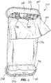
- Figures 1 and 2 illustrate a filter 310.
- the filter 310 can move between a collapsed position ( FIG. 1 ) and an expanded position ( FIG. 2 ).
- the filter 310 may be supplied to the consumer in the collapsed position.
- the filter 310 is installed in a device in the collapsed position and then automatically moves to the expanded position.
- the filter 310 can automatically move to the expanded position by air pressure, gravity, mechanical push or pull, etc.
- the consumer moves the filter to the expanded position prior to installing the filter into a device.
- the filter 310 can be used to filter any suitable fluid in several applications.
- the filter 310 can be used in vacuum cleaners, air purifiers, HVAC systems, automotive applications, etc.
- the filter 310 includes a first or upper housing 312, a second or lower housing 314, and filter media 316.
- the upper housing 312 includes an inlet opening 318 that provides fluid communication into the filter 310.
- a valve 319 is located within the inlet opening 318 to open and close the inlet opening 318. For example, when the filter 310 is ready to be removed from the device (e.g., vacuum), the valve 319 is closed so that debris within the filter 310 does not escape through the inlet opening 318.
- the upper housing 312 has an inner volume 320 (see FIG. 5A ) within the housing 312.
- the lower housing 314 includes an inner volume 321.
- the inner volumes 320, 321 of the upper housing 312 and the lower housing 314 can be equal or one of the volumes can be greater than the other. In various alternatives, the inner volumes of one or both of the upper housing and the lower housing are small or inappreciable due to the shape of the housing.
- the upper housing 312 and the lower housing 314 can be formed from any suitable material, such as thermoplastic material, thermoset material, molded paper pulp, formed or molded filter media, or any other suitable material. Alternatively or additionally, the upper housing 312 forms a support collar 323 for installing the filter 310 in a vacuum cleaner.
- the filter media 316 includes a first end 322 and a second end 324.
- the filter media 316 is coupled to the upper housing 312 proximate the first end 322 while, the filter media 316 is coupled to the lower housing 314 proximate the second end 324.
- An inner volume 326 of the filter media 316 is defined between the first end 322 and the second end 324 of the filter media 316.
- the filter media 316 includes one or more pleats 328 extending between the first end 322 and the second end 324. The pleats 328 enable the filter 310 to enlarge beyond the expanded position in a direction transverse to the direction traveled between the collapsed and expanded positions.
- the pleats 328 allow the filter 310 to billow outward in order to collect and store additional debris as the filter 310 fills.
- the illustrated filter media 316 typically includes a seam 330.
- the filter media 316 is a flat piece that is made tubular by joining two ends together, thereby creating the seam 330.
- the seam 330 is located within one of the pleats 328 to substantially hide the seam 330.
- the seam 330 can be formed by sewing, heat welding, crimping, or other suitable means of coupling the two ends together.
- the filter 310 can move between a collapsed position ( FIG. 1 ) and an expanded position ( FIG. 2 ).
- the filter media 316 is located within the inner volume 320 of the upper housing 312 and/or in the inner volume of the lower housing 314.
- the upper housing 312 and the lower housing 314 enclose the filter media 316 in the collapsed position.
- the upper housing 312 and/or lower housing 314 can snap or otherwise connect together to retain the filter 310 in the collapsed position by interlocking features provided in the upper and lower housings.
- the filter 310 may be held in the collapsed position by tape, film, bag, or other attachments.
- the filter 310 would be supplied to the user in the collapsed position.
- the filter media 316 In the expanded position, the filter media 316 generally expands out to an operative length and is ready for use as a filter.
- the filter 310 automatically moves from the collapsed position to the expanded position. For example, when a flow of dirty fluid enters the filter 310 through the inlet opening 318, the pressure of the fluid automatically expands the filter 310. In other applications, gravity may automatically expand the filter 310, or a mechanism may be used to push or pull one or both housings away from the other.
- a dirty fluid e.g., air and dust, dirt, or other particles
- the filter 310 further includes a first attachment member 336 that couples the filter media 316 to the upper housing 312.
- the filter media is folded over the first attachment member 336 between the first end 322 and the second end 324 of the filter media 316, but generally closer to the first end 322, before it is connected to the upper housing 312. Stated another way, all or a portion of the first end 322 of the filter media 316 is folded over before being coupled to the upper housing 312.
- the filter 310 includes a second attachment member 338 that couples the filter media 316 to the lower housing 314 between the first end 322 and the second end 324 of the filter media 316, but closer to the second end 324.
- the first attachment member 336 is received within a groove 340 of the upper housing 312 holding the filter media in place, whereas the second attachment member 338 is received within a groove 342 of the lower housing 314.
- the grooves 340, 342 are formed with an inner wall 341 and an outer wall 343.
- the height HI of the outer wall 343 is greater than the height H2 of the inner wall 341.
- the height HI of the outer wall 343 is the same as the height H2 of the inner wall 341.
- the filter media 316 is folded over the first attachment member 336 and fitted into the groove 340 of the upper housing 312. As such, the filter media 316 is disposed between the groove 340 and the first attachment member 336.
- the fit between the groove 340 and the attachment member 336 with filter media 316 is a friction or limited clearance fit to wedge the filter media 316 and attachment member 336 into the groove 340 to couple the filter media 316 to the upper housing 312.
- the attachment member 336 is staked, welded, snap fit, adhered, or otherwise fastened to the upper housing 312 to couple the filter media 316 to the upper housing 312.
- At least a portion of the edge 322 of the first end 322 of the filter media 316 is retained in the groove 340 by fitting the attachment member 336 into the groove 340.
- the connection of the filter media 316 to the upper housing 312 is provided around the upper housing 312 inhibiting airflow through the connection.
- the filter media 316 is wrapped around the second attachment member 338 and fitted into the groove 342 of the lower housing 314 in a similar way as described for the filter media 316 coupling to the upper housing 312. As such, the filter media 316 is retained in the groove 342 by fitting the second attachment member 338 into the groove 342.
- the connection of the filter media 316 to the lower housing 314 is provided around the lower housing 314 inhibiting airflow through the connection.
- the connection of the filter media 316 to the lower housing 314 may use a different method than the connection to the upper housing 312.
- the filter media 316 does not use a lower housing 314, instead closing the second end 324 with a seam or other closure.
- the filter 310 may include a first overlapping filter media section 344 and a second overlapping filter media section 346.
- the first overlapping filter media section 344 is proximate the upper housing 312 and is a result of the first end 322 of the filter media 316 being folded such that at least a portion of the first end 322 extends away from the housing 312 forming the overlapping filter media section 344.
- the first end 322 of the filter media 316 is folded over the attachment member 336 in a manner that the first end 322 extends away from the upper housing 312 a desired length.
- the filter media 316 overlaps to provide two layers at the first overlapping filter media section 344.
- the first overlapping filter media section 344 may extend around the perimeter of the filter 310 or may extend along one or more portions of the perimeter of the filter 310. In certain embodiments, all or desired portions of the overlapping filter media 344 may be trimmed, or filter media 316 positioned such that a desired amount of filter media 316 extends beyond the attachment member 336 in predetermined locations. In the embodiment (which is not part of the invention) shown in FIG. 15A , the first overlapping filter media section 344 includes a notch 345 in a portion. The notch 345 inhibits parts of a vacuum (e.g., a conduit that extends into the filter) from catching on the filter media when the conduit inserted and removed from the filter.
- a vacuum e.g., a conduit that extends into the filter
- the second overlapping filter media section 46 is proximate the lower housing 314 and is a results of the second attachment member 338 bending the filter media 316 in a manner that the second end 324 extends away from the lower housing 314. As such, the filter media 316 overlaps to provide two layers and forms the second overlapping filter media section 346.
- the second overlapping filter media section 346 may extend around the perimeter of the filter 310 or may extend along one or more portions of the perimeter of the filter 310. In certain embodiments, all or desired portions of the overlapping filter media 46 may be trimmed, or filter media 316 positioned such that a desired amount of filter media 316 extends beyond the second attachment member 338 in predetermined locations.
- both of the first and second overlapping filter media sections 344, 346 are disposed in the inner volume 326 of the filter media 316.
- the filter 310 may be constructed with the overlapping filter media portions 344, 346 being positioned to the outside of the filter 310.
- the upper housing 312 may include one or more extension members 348 adjacent the groove 340.
- the extensions members 348 are positioned in a location to direct the overlapping filter media section 344 to extend in a direction along the outer wall 343 of the upper housing 312 and filter media 316.
- the extension members 348 may be integrally formed with the upper housing 312 or may be formed separately and installed in the filter 310.
- the first overlapping filter media section 344 is proximate the upper housing 314.
- the length and width and location of the first overlapping filter media section 344 or the second overlapping filter media section 346 may be provided where it is in a direct path of some or all of the airflow (see arrow 334 of FIG. 7A ) exiting the device (e.g., a discharge conduit of a vacuum) to receive impact of impinging debris as the debris enters the filter 310.
- One or both of the attachment members 336, 338 may include a recess, protrusion, or other shape 350 configured for nesting or attaching to a fixture provided to guide the attachment member 336, 338 into the groove 340, 342.
- the attachment member 336, 338 may include the fixturing recess, protrusion, or other shape 350 on the side facing out of the groove 340, 342.
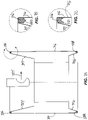
- FIG. 8A and 8B illustrate a filter 410.
- the filter 410 can move between a collapsed position ( FIG. 8A ) and an expanded position ( FIG. 8B ).
- the filter 410 may be supplied to the consumer in the collapsed position.
- the filter 410 is installed in a device in the collapsed position and then automatically moves to the expanded position.
- the filter 410 can automatically move to the expanded position by air pressure, gravity, mechanical push or pull, etc.
- the consumer moves the filter to the expanded position prior to installing the filter into a device.
- the filter 410 can be used to filter any suitable fluid in several applications.
- the filter 410 can be used in vacuum cleaners, air purifiers, HVAC systems, automotive applications, etc.
- the filter 410 includes a first or upper housing 412, a second or lower housing 414, and filter media 416.
- the upper housing 412 includes an inlet opening 418 that provides fluid communication into the filter 410.
- a valve is located within the inlet opening 418 to open and close the inlet opening 418. For example, when the filter 410 is ready to be removed from the device (e.g., vacuum), the valve is closed so that debris within the filter 410 does not escape through the inlet opening 418.
- the upper housing 412 has an inner volume 420 (see FIG. 16A ) within the housing 412.
- the lower housing 414 includes an inner volume.
- the inner volumes of the upper housing 412 and the lower housing 414 can be equal or one of the volumes can be greater than the other.
- the upper housing 412 and the lower housing 414 can be formed from any suitable material, such as thermoplastic material, thermoset material, molded paper pulp, formed or molded filter media, or any other suitable material.
- the filter media 416 includes a first end 422 (see FIG. 16A , which illustrates an embodiment that is not part of the invention).
- the filter media 416 is coupled to the upper housing 412 at the first end 422.
- the filter media 416 has a second end and the filter media 416 is coupled to the lower housing 414 at the second end.
- the first and second ends of the filter media 416 can be attached to the housings 412, 414 using a variety of methods.
- An inner volume 424 (see FIG. 16A ) of the filter media 416 is defined between the first end 422 and the second end (not shown in FIG. 16A ) of the filter media 416.
- a dirty fluid e.g., air and dust, dirt, or other particles
- a panel 428 is located at a seam of the filter media 416, for example along a vertical seam.
- the panel 428 is clear to allow a user to see how much debris is in the filter 410 to indicate to the user when the collection container 425 is full.
- the panel 428 can be decorative and/or can include odor absorbing material.
- the filter may be constructed such that the optional panel 428 may be provided along a horizontal seam.
- the filter media 416 is divided into two sections, and the filter media 416 is attached to the housing 412.
- the second piece of filter media 416' is attached to the filter media 416, optionally with the panel 428 provided along the horizontal seam between the filter media sections 416, 416'.
- the filter 410 can move between a collapsed position ( FIG. 8A ) and an expanded position ( FIG. 8B ).
- the filter media 416 is located within the inner volume 420 (the inner volume being shown in one embodiment in FIG. 16A ) of the upper housing 412 and/or in the inner volume of the lower housing 414.
- the upper housing 412 and the lower housing 414 enclose the filter media 416 in the collapsed position.
- the upper housing 412 and/or lower housing 414 can snap or otherwise connect together to retain the filter 410 in the collapsed position by interlocking features provided in the upper and lower housings.
- the filter 410 may be held in the collapsed position by tape, film, bag, or other attachments. Typically, the filter 410 would be supplied to the user in the collapsed position. In the expanded position, the filter media 416 generally expands out to an operative length and is ready for use as a filter. In some applications, the filter 410 automatically moves from the collapsed position to the expanded position. For example, referring to FIG. 27A, when a flow of dirty fluid (represented by arrows 426) enters the filter 410 through the inlet opening 418, the pressure of the fluid automatically expands the filter 410. In other applications, gravity may automatically expand the filter 410, or a mechanism may be used to push or pull one or both housings away from the other.
- a flow of dirty fluid represented by arrows 426
- gravity may automatically expand the filter 410, or a mechanism may be used to push or pull one or both housings away from the other.
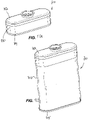
- FIGs. 9A and 9B illustrate a filter 510 according to another embodiment.
- the filter 510 includes features similar to the filter 410 of FIGs. 8A and 8B and only some differences between the filters 410, 510 will be discussed.
- the filter 510 includes a lower housing 514 that is generally flat and has very little inner volume. In the illustrated embodiment, in the collapsed position, the filter media 516 is virtually entirely received in the inner volume of the upper housing 512. In this embodiment, the lower housing 514 functions as a cap to close the upper housing 512 and retain the filter media 516 in the collapsed position. Alternatively, at least a portion of the filter media 516 is received in the inner volume of the upper housing 512.
- FIGs. 10A and 10B illustrate a filter 610 according to another embodiment.
- the filter 610 includes features similar to the filters discussed above and only some differences between the filters will be discussed.
- the filter 610 includes an upper housing 612 that is generally flat and has very little inner volume. In the illustrated embodiment, in the collapsed position, the filter media 616 is virtually entirely received in the inner volume of the lower housing 614.
- the upper housing 612 functions as a cap to close the lower housing 614 and retain the filter media 616 in the collapsed position. At least a portion of the filter media 616 is received in the inner volume of the upper housing 612
- FIGs. 11A, 11B , 12A and 12B illustrate a filter 710 according to another embodiment.
- the filter 710 includes features similar to the filters discussed above and only some differences between the filters will be discussed.
- the filter 710 includes an upper housing 712 and a lower housing 714 and both of the upper and lower housings may have an inner volume.
- the filter 710 further includes an intermediate portion 730.
- the intermediate portion 730 is a tear-away style component that remains attached to either the upper housing 712 or the lower housing 714. For example, there is a perforation or similar attachment between the intermediate portion 730 and the upper housing 712 and/or lower housing 714.
- FIG. 11B illustrates the intermediate portion 730 remaining attached to the upper housing 712 in the expanded position.
- FIG. 12B illustrates the intermediate portion 730 remaining attached to the lower housing 714 in the expanded position.
- the intermediate portion is connected to the upper housing and/or lower housing with engaging features such as snap-fits, friction-fits, protrusions, tabs, hooks, interlocks, or other features that engage corresponding features such as recesses, openings, snap-fits, friction-fits, tabs, protrusions, hooks, interlocks, or other features to connect the intermediate portion with the adjacent housing.
- Engaging features between the intermediate portion and adjacent housings may be configured so that the connection to one of the adjacent housings is stronger than the connection to the other housing to control whether the intermediate portion remains with the upper housing or the lower housing when moving to the expanded position.
- FIGs. 13A and 13B illustrate a filter 810 according to another embodiment, which is not part of the invention and is for illustration purposes only.
- the filter 810 includes features similar to the filters discussed above and only some differences between the filters will be discussed.
- the filter 810 includes an upper housing 812 and a lower housing 814 and either or both of the upper and lower housings may be generally flat or may have an inner volume.
- the filter 810 further includes an intermediate portion 830, and in the collapsed position, the filter media 816 is virtually entirely received between the housings 812, 814 and surrounded and enclosed by the intermediate portion 830.
- the intermediate portion 830 is a tear-away style component that the user removes (as illustrated in FIG.
- the intermediate portion 830 can be formed by paper, film, tape, paperboard, a sleeve, or other suitable components.
- the intermediate portion and the lower housing are combined into one removable or tear-away component, with the bottom of the filter media being closed with a seam.
- FIGs. 14A and 14B illustrate a filter 910 that is not part of the present invention and is for illustration purposes only.
- the filter 910 includes features similar to the filters discussed above and only some differences between the filters will be discussed.
- the filter 910 includes an upper housing 912 similar to the housing 412 of the filter 410 of FIGs. 8A and 8B .
- the filter 910 further includes a lower end 932 of the filter media 916 that is closed with a seam, illustrated in FIG. 14B as a flat seam or rolled seam. In the collapsed position, the filter media 916 is entirely received in the inner volume of the upper housing 912. In some alternatives, the filter media 916 is enclosed in the collapsed position in the upper housing 912 by a closure device on the bottom of the upper housing 912.
- the closure device can include film, foil, paper, a cap, tape, bag, sleeve, or other suitable devices holding the filter media 916 and the upper housing 912 in the collapsed position.
- the closure device may include a perforation, slit, tear line, or hinge that allows the filter media 916 to move to the expanded position.
- the closure device or cover would remain in place during and after installation of the filter 910 in the device.
- the device may include a feature that automatically opens or shears the cover allowing the filter media to move to the expanded position.
- airflow from the device through the inlet opening 918 causes the filter media 916 to automatically expand and tear, push, and/or swing open the closure device, automatically expanding the filter 910.
- the closure device may be removed, such as by peeling or tearing, by the user before or immediately after installing the filter 910.
- FIGs. 15A - 15C illustrate a filter 1010 that is not part of the present invention and is for illustration purposes only.
- the filter 1010 includes features similar to the filters discussed above and only some differences between the filters will be discussed.
- the filter 1010 includes an upper housing 1012 similar to the housing 412 of the filter 410 of FIGs. 8A and 8B or any other disclosed embodiment.
- the filter 1010 further includes a lower end of the filter media 1016 that includes a gusset bottom 1034.
- the gusset bottom 1034 can be formed from media material, thermoplastic molded or die cut material, film, foil, or other suitable materials. In some alternatives, the gusset bottom 1034 is air permeable.
- the gusset bottom 1034 can be a self-standing type gusset.
- the filter media 1016 is at least partially received in the inner volume of the upper housing 1012.
- the filter media 1016 is enclosed in the collapsed position in the upper housing 1012 by a closure device on the bottom of the upper housing 1012.
- the closure device can include film, foil, paper, a cap, tape, bag, sleeve, or other suitable devices holding the filter media 1016 and the upper housing 1012 in the collapsed position.
- the closure device may include a perforation 1069, slit, tear line, or hinge that allows the filter media 1016 to move to the expanded position. In some alternatives, the closure device or cover would remain in place during and after installation of the filter 1010 in the device.
- the device may include a feature that automatically opens or shears the cover.
- airflow from the device through the inlet opening 1018 causes the filter media 1016 to automatically expand and tear, push, and/or swing open the closure device, automatically expanding the filter 1010.
- the closure device may be removed, such as by peeling or tearing, by the user before or immediately after installing the filter 1010.
- FIG. 16A illustrates one possible way to attach the filter media 416 to the upper housing 412 (or any of the upper housings described herein).
- the filter media 416 is welded onto an inside surface 436 of a sidewall 438 of the upper housing 412 at the first end 422 of the filter media 416.
- the media 416 can also be attached to the housing 412 using adhesive.
- the housing 412 may be overmolded onto the filter media 416.
- FIG. 16B illustrates the attachment described above with regard to FIG. 16A except that the housing 412 has a different shaped sidewall 438 and the end 422 of the filter media 416 abuts a top wall 440 of the housing 412.
- the attachment is generally radial or transverse to the direction of the filter media, with a mandrel, horn, or other attachment process support being provided through the lower end of the filter prior to the lower end being closed.
- FIG. 17A illustrates another possible way to attach the filter media 416 to the upper housing 412 (or any of the upper housings described herein).
- the filter media 416 is welded onto an inside surface 442 of the top wall 440 of the upper housing 412 at the first end 422 of the filter media 416.
- the media 416 can be attached to the housing 412 using adhesive.
- the housing 412 may be overmolded onto the filter media 416.
- FIG. 27B illustrates the attachment described above with regard to FIG. 17A except that the housing 412 has a different shaped sidewall 438.
- the attachment is generally axial or along the direction of the filter media, with a mandrel, horn, or other attachment process support being provided through the lower end of the filter prior to the lower end being closed.
- FIGs. 18A - 18C illustrate how the first end 422 of the filter media 416 may be prepared before attaching the filter media 416 to the housing 412 (similarly, how the second end of the filter media 416 could be prepared before attachment to the lower housing 414).
- FIG. 18A illustrates the first end 422 of the filter media 416 in its original thickness and the first end 422 can be attached to the housing 412 in its original thickness.
- the filter media 416 can be compressed along the first end 422 to create an area 441 of reduced thickness and increased density. The area 441 of reduced thickness is where the welding or overmolding to the housing 412 will be made.
- FIG. 18A illustrates the first end 422 of the filter media 416 in its original thickness and the first end 422 can be attached to the housing 412 in its original thickness.
- the filter media 416 can be compressed along the first end 422 to create an area 441 of reduced thickness and increased density.
- the area 441 of reduced thickness is where the welding or overmolding to the housing 412
- 18C illustrates another embodiment where a secondary strip of material 442 is welded other otherwise attached to the end 422 of the filter media 416. Then, the secondary strip of material 442 is welded, overmolded, or otherwise attached to the housing 412. In some embodiments, the secondary strip of material 442 includes a film and/or extrusion and can be applied to one or both sides of the filter media 416.
- FIGs. 19 and 20 illustrate one possible method of attaching the housings 412, 414 (or other housings discussed herein) onto the filter media 416 by overmolding.
- the filter media 416 is placed into the mold 444 over the mold core being provided through the lower end of the filter prior to the lower end being closed.
- the material of the housings 412, 414 is injected over the filter media 416.
- the filter media 416 having the reduced thickness 441 at the end 422 is utilized.
- the mold 444 shuts off or closes against the media 416 at the area 441 of reduced thickness (near area of arrow 446 in FIG. 20 ).
- the injected material adheres to the filter media 416 along the area of reduced thickness 441 to attach the filter media 416 to the housings 412, 414.
- filter media having end treatment shown in FIG. 18A, 18B, and 18C may be utilized.
- the filter media 416 may be divided into at least two portions, with the first portion of the filter media 416 being attached to the upper housing 412. Attaching a smaller portion of media to the upper may be useful in handing the filter media in a welding or molding process where internal support is needed. Then, after attachment of the first portion to the upper housing, the second piece of filter media 416' is attached to the first portion of filter media 416 using traditional bonding, sewing, or welding techniques. In one embodiment, not shown, the panel 428 is attached directly to the upper housing by welding, overmolding, adhesive, or other technique, and the filter media 416 is attached to the panel.
- FIG. 21A illustrates a possible way to attach the filter media 416 to the lower housing 414 (or any of the lower housings described herein), which is not part of the invention and is for illustration purposes only.
- the filter media 416 is welded onto an outside surface 446 of a sidewall 448 of the lower housing 414 at the second end 423 of the filter media 416.
- the filter media 416 can also be attached to the housing 414 using adhesive.
- FIG. 21B illustrates one possible way to attach the filter media 316 to a flat lower housing 314 (similarly could be used to attach to a flat upper housing 412 or any of the housings described above).
- a ring 450 optionally having projections 452 may be fitted to capture the lower end of the filter media 416 between the ring and the housing 414 and may be heat staked or otherwise fastened to attach the filter media 416 and the housing 414.
- FIG. 22 illustrates an alternative embodiment, which is not part of the invention and is for illustration purposes only, where a portion 454 of the upper housing 412 is formed by the filter media 416, generally by making the filter media 416 in the portion 454 more rigid or stiffer than the other areas of the filter media 416.
- the portion 454 is stiffened by compression molding, vacuum thermoforming, or a combination of both, and/or coating/impregnating the portion 454 with thermoset, thermoplastic, or other material to make a rigid or semi rigid upper portion having a desired shape made with the filter media 416.
- An inlet piece 456, including the inlet opening 418, is inserted through an aperture 457 of the portion 454.
- the inlet piece 456 can be attached by welding or adhesive.
- the inlet piece 456 is attached to the inside of the portion 454 and in other embodiments, the inlet piece 456 may be attached to the outside of the portion 454. In another embodiment, the inlet piece is overmolded onto the filter media before, during, or after the stiffening operation.
- FIG. 23 illustrates an alternative embodiment, which is not part of the invention and is for illustration purposes only, where the filter media 416 is formed with a generally closed end except for aperture 458. Then, the filter media 416 is attached to the housing 412 with the aperture 458 aligned with the inlet opening 418. The attachment could be made by welding or adhesive around the aperture 458.
- FIGs. 24 and 25 illustrate an alternative to the technology that is not part of the present invention and is for illustrative purposes only, where the housing 412 or housing 414 are formed by folding a die cut shape 460 ( FIG. 25 ).
- the shape 460 is die cut and then folded to create the housing 412 or 414.
- the filter media can be attached to the housings 412 or 414 by welding or adhesive.
- the housing can be formed from a single piece hinged from a top piece. The top and bottom die cut pieces could be separated and then bonded to each other or separately to the filter media by the methods previously discussed.
- FIGs. 26 and 27 illustrate a filter 1110 according to an alternative to the technology that is not part of the present invention and is for illustrative purposes only.
- the filter 1110 includes features similar to the filters discussed above and only some differences between the filters will be discussed.
- the filter 1110 includes an upper housing 1112 that includes a bag 112.
- filter media 1116 is formed as a complete enclosure with a desired inlet 1118.
- the filter media is compacted and inserted into an open end of the bag 1112 and then the bag sealed, or alternatively, the bag 1112 formed and sealed around the compacted media.
- the bag 1112 is attached to the filter material around the inlet 1118.
- the bag 1112 can be formed from foil, plastic, paper, or other suitable materials.
- the bag 1112 includes a tear-out bottom 1164 opposite the inlet 1118 at the top of the bag 1112.
- the bag 1112 is installed into the device with the filter media 1116 in the collapsed position ( FIG. 26 ). Then, when the device is used or turned on, the filter media 1116 automatically breaks through the bottom 1164 of the bag 1112 because of the airflow through the inlet 1118.
- the bag includes a portion that the user opens before loading into a device, such as a tear-away portion, tear or cut line, or other opening.
- a mechanism may be used to push or pull one end of the filter away from the other moving the filter to the expanded position.
Landscapes
- Engineering & Computer Science (AREA)
- Mechanical Engineering (AREA)
- Chemical & Material Sciences (AREA)
- Chemical Kinetics & Catalysis (AREA)
- Filters For Electric Vacuum Cleaners (AREA)
- Filtering Of Dispersed Particles In Gases (AREA)
Claims (10)
- Filter (310), der konfiguriert ist, um Schmutz von einem Fluidstrom zu trennen, wobei der Filter umfasst:ein Gehäuse mit einem ersten Innenvolumen (320);ein Filtermedium (316), das ein erstes Ende (322), ein zweites Ende (324) und ein zweites Innenvolumen (326) zwischen dem ersten und dem zweiten Ende aufweist, wobei das Filtermedium an dem ersten Ende des Filtermediums derart gekoppelt sind, dass das erste und das zweite Innenvolumen zusammen zumindest teilweise einen Sammelbehälter definieren, der konfiguriert ist, um den durch das Filtermedium getrennten Schmutz von dem Fluidstrom zu speichern; undeine Einlassöffnung (318), die sich durch das Gehäuse erstreckt, um eine Fluidverbindung in den Sammelbehälter bereitzustellen, sodass der Fluidstrom mit Schmutz in den Sammelbehälter fließen kann und ein relativ sauberer Fluidstrom durch das Filtermedium zwischen dem ersten und dem zweiten Ende des Filtermediums austritt, unddadurch gekennzeichnet, dass das Filtermedium in eine zusammengeklappte Position beweglich sind, in der das Filtermedium in das erste Innenvolumen des Gehäuses und von der zusammengeklappten Position in eine ausgeweitete Position geklappt wird,wobei das Gehäuse ein erstes Gehäuse (312) ist, wobei das Filter ferner ein zweites Gehäuse (314) umfasst, wobei das Filtermedium an dem zweiten Ende des Filtermediums mit dem zweiten Gehäuse gekoppelt ist, wobei das zweite Gehäuse und das erste Gehäuse das Filtermedium umschließen, wenn das Filtermedium in das erste Gehäuse zusammengeklappt wird, undwobei das erste Innenvolumen des ersten Gehäuses, zusammen mit dem zweiten Innenvolumen des Filtermediums, und ein drittes Innenvolumen (321) des zweiten Gehäuses zusammen einen Sammelbehälter (332) definieren, der durch das Filtermedium getrennten Schmutz lagert.
- Filter nach Anspruch 1, ferner umfassend ein Ventil (319) in der Einlassöffnung, wobei das Ventil zwischen einer geöffneten Position und einer geschlossenen Position beweglich ist.
- Filter nach Anspruch 1, wobei das Filtermedium eine Naht (330) einschließt, die sich von dem ersten Ende zu dem zweiten Ende des Filtermediums erstreckt, wobei das Filter ferner eine Wand umfasst, die sich entlang der Naht erstreckt.
- Filter nach Anspruch 3, wobei die Wand durchsichtig ist.
- Filter nach Anspruch 1, wobei das Gehäuse aus einem Kunststoffmaterial gebildet ist.
- Filter nach Anspruch 1, wobei das zweite Gehäuse mit dem ersten Gehäuse gekoppelt ist, wenn das Filtermedium in das erste Gehäuse geklappt ist.
- Filter nach Anspruch 1, wobei ein Abschnitt des zweiten Gehäuses flach ist.
- Filter nach Anspruch 1, wobei das erste Ende des Filtermediums mit dem Gehäuse verschweißt ist.
- Filter nach Anspruch 1, wobei das Gehäuse auf das erste Ende des Filtermediums umspritzt ist.
- Filter nach Anspruch 1, wobei das erste Ende des Filtermediums durch Klebstoff an dem Gehäuse befestigt ist.
Applications Claiming Priority (5)
| Application Number | Priority Date | Filing Date | Title |
|---|---|---|---|
| US201662323384P | 2016-04-15 | 2016-04-15 | |
| US201662361718P | 2016-07-13 | 2016-07-13 | |
| US201762457543P | 2017-02-10 | 2017-02-10 | |
| US201762457329P | 2017-02-10 | 2017-02-10 | |
| PCT/US2017/027684 WO2017181048A1 (en) | 2016-04-15 | 2017-04-14 | Vacuum filter |
Publications (2)
| Publication Number | Publication Date |
|---|---|
| EP3442679A1 EP3442679A1 (de) | 2019-02-20 |
| EP3442679B1 true EP3442679B1 (de) | 2022-11-09 |
Family
ID=60039697
Family Applications (4)
| Application Number | Title | Priority Date | Filing Date |
|---|---|---|---|
| EP17721234.7A Active EP3442679B1 (de) | 2016-04-15 | 2017-04-14 | Vakuumfilter |
| EP17732618.8A Active EP3442680B1 (de) | 2016-04-15 | 2017-04-14 | Handstaubsauger |
| EP21150315.6A Withdrawn EP3831460A1 (de) | 2016-04-15 | 2017-04-14 | Handstaubsauger |
| EP17733101.4A Active EP3442392B1 (de) | 2016-04-15 | 2017-04-14 | Staubsauger und filter für einen staubsauger |
Family Applications After (3)
| Application Number | Title | Priority Date | Filing Date |
|---|---|---|---|
| EP17732618.8A Active EP3442680B1 (de) | 2016-04-15 | 2017-04-14 | Handstaubsauger |
| EP21150315.6A Withdrawn EP3831460A1 (de) | 2016-04-15 | 2017-04-14 | Handstaubsauger |
| EP17733101.4A Active EP3442392B1 (de) | 2016-04-15 | 2017-04-14 | Staubsauger und filter für einen staubsauger |
Country Status (5)
| Country | Link |
|---|---|
| US (5) | US10470625B2 (de) |
| EP (4) | EP3442679B1 (de) |
| CN (3) | CN109475802B (de) |
| AU (4) | AU2017250824B2 (de) |
| WO (3) | WO2017181041A2 (de) |
Families Citing this family (57)
| Publication number | Priority date | Publication date | Assignee | Title |
|---|---|---|---|---|
| US11793374B2 (en) * | 2006-12-12 | 2023-10-24 | Omachron Intellectual Property Inc. | Surface cleaning apparatus with a variable inlet flow area |
| US10722086B2 (en) * | 2017-07-06 | 2020-07-28 | Omachron Intellectual Property Inc. | Handheld surface cleaning apparatus |
| US11707173B2 (en) | 2014-07-18 | 2023-07-25 | Omachron Intellectual Property Inc. | Surface cleaning apparatus |
| CA168784S (en) * | 2015-12-01 | 2017-04-28 | Lg Electronics Inc | Vacuum cleaner body |
| CA168782S (en) * | 2015-12-01 | 2017-03-16 | Lg Electronics Inc | Vacuum cleaner body |
| CA168783S (en) * | 2015-12-01 | 2017-04-28 | Lg Electronics Inc | Vacuum cleaner body |
| CA168785S (en) * | 2015-12-01 | 2017-04-28 | Lg Electronics Inc | Vacuum cleaner body |
| US11839343B2 (en) | 2019-08-15 | 2023-12-12 | Omachron Intellectual Property Inc. | Handheld surface cleaning apparatus |
| KR102560970B1 (ko) | 2016-03-31 | 2023-07-31 | 엘지전자 주식회사 | 청소기 |
| TWI809509B (zh) | 2016-03-31 | 2023-07-21 | 南韓商Lg電子股份有限公司 | 吸塵器 |
| WO2017171496A1 (ko) | 2016-03-31 | 2017-10-05 | 엘지전자 주식회사 | 청소기 |
| US11166607B2 (en) | 2016-03-31 | 2021-11-09 | Lg Electronics Inc. | Cleaner |
| EP3442679B1 (de) * | 2016-04-15 | 2022-11-09 | Techtronic Floor Care Technology Limited | Vakuumfilter |
| US11478117B2 (en) | 2016-08-29 | 2022-10-25 | Omachron Intellectual Property Inc. | Surface cleaning apparatus |
| US10441124B2 (en) * | 2016-08-29 | 2019-10-15 | Omachron Intellectual Property Inc. | Surface cleaning apparatus |
| US12426753B2 (en) * | 2017-11-16 | 2025-09-30 | Irobot Corporation | Washable bin for a robot vacuum cleaner |
| AU201812645S (en) * | 2017-12-05 | 2018-07-31 | Tti Macao Commercial Offshore Ltd | Housing for a vacuum filter |
| DE102017128795A1 (de) * | 2017-12-05 | 2019-06-06 | Miele & Cie. Kg | Staubsauger |
| GB2569591B (en) * | 2017-12-20 | 2020-07-15 | Dyson Technology Ltd | Vacuum cleaner |
| US10792606B2 (en) * | 2018-03-07 | 2020-10-06 | Tti (Macao Commercial Offshore) Limited | Vacuum cleaner |
| US10722089B2 (en) | 2018-03-27 | 2020-07-28 | Omachron Intellectual Property Inc. | Surface cleaning apparatus |
| US10791890B2 (en) | 2018-03-27 | 2020-10-06 | Omachron Intellectual Property Inc. | Surface cleaning apparatus |
| KR20190117173A (ko) * | 2018-04-06 | 2019-10-16 | 엘지전자 주식회사 | 청소기 및 그 제어방법 |
| CN108465308B (zh) * | 2018-05-14 | 2020-06-09 | 江苏东方滤袋股份有限公司 | 一种非织造除尘滤袋 |
| KR102081942B1 (ko) * | 2018-05-31 | 2020-02-26 | 엘지전자 주식회사 | 청소기 |
| US10368706B1 (en) | 2018-07-17 | 2019-08-06 | Shop Vac Corporation | Vacuum filter having annular catch |
| US10882059B2 (en) | 2018-09-21 | 2021-01-05 | Omachron Intellectual Property Inc. | Multi cyclone array for surface cleaning apparatus and a surface cleaning apparatus having same |
| CN217096845U (zh) | 2018-08-31 | 2022-08-02 | 米沃奇电动工具公司 | 电动工具 |
| GB2578873B (en) * | 2018-11-09 | 2021-08-18 | Dyson Technology Ltd | A vacuum cleaner and a filter assembly |
| KR20200073966A (ko) | 2018-12-14 | 2020-06-24 | 삼성전자주식회사 | 진공 청소기와 도킹 스테이션을 포함하는 청소 장치 |
| USD930297S1 (en) * | 2019-02-27 | 2021-09-07 | Techtronic Floor Care Technology Limited | Floor cleaner |
| DE102019109596A1 (de) * | 2019-04-11 | 2020-10-15 | Vorwerk & Co. Interholding Gmbh | System aus einem manuell geführten Bodenbearbeitungsgerät, einem ausschließlich automatisch betriebenen Bodenbearbeitungsgerät und einer Recheneinrichtung |
| US11224324B2 (en) | 2019-08-15 | 2022-01-18 | Omachron Intellectual Property Inc. | Handheld surface cleaning apparatus |
| EP3821777B1 (de) | 2019-11-12 | 2025-01-01 | Eurofilters Holding N.V. | Staubsaugerfilterbeutel für einen handstaubsauger |
| PL3821776T3 (pl) | 2019-11-12 | 2025-03-17 | Eurofilters Holding N.V. | Worek filtrujący do odkurzacza ręcznego |
| CN113116212B (zh) * | 2020-01-16 | 2025-03-04 | 江苏美的清洁电器股份有限公司 | 吸尘器 |
| KR102904609B1 (ko) * | 2020-02-18 | 2025-12-29 | 엘지전자 주식회사 | 청소기 및 청소기의 제어방법 |
| WO2021235395A1 (ja) * | 2020-05-21 | 2021-11-25 | シャープ株式会社 | 電気掃除機 |
| PL4199795T3 (pl) * | 2020-08-20 | 2024-10-28 | Aktiebolaget Electrolux | Kompaktowy worek na kurz do odkurzacza |
| EP4059406B1 (de) | 2021-03-17 | 2026-02-25 | Dupray Ventures Inc. | Fleckenreinigungsgerät |
| DE102021001978A1 (de) * | 2021-04-15 | 2022-10-20 | Mahle International Gmbh | Filterbaugruppe |
| US20220395151A1 (en) * | 2021-06-14 | 2022-12-15 | Sharon Elizabeth Phillip | Modular household blower system |
| USD1064465S1 (en) * | 2021-12-23 | 2025-02-25 | Tineco Intelligent Technology Co., Ltd. | Vacuum cleaner |
| USD1031192S1 (en) * | 2022-01-14 | 2024-06-11 | Guangdong Xingchen Technology Development Co., Ltd. | Portable vacuum |
| JP1782368S (ja) * | 2022-03-29 | 2024-10-16 | 掃除機 | |
| USD1017156S1 (en) | 2022-05-09 | 2024-03-05 | Dupray Ventures Inc. | Cleaner |
| USD970833S1 (en) * | 2022-05-24 | 2022-11-22 | Min Ying | Floor cleaner |
| USD1035190S1 (en) * | 2022-06-23 | 2024-07-09 | Jiang Dong | Floor cleaner |
| USD1059707S1 (en) * | 2022-07-11 | 2025-01-28 | Shenzhen Longood Intelligent Electric Co., Ltd | Combined smart floor cleaning, mopping and vacuum machine |
| USD1055433S1 (en) * | 2022-08-23 | 2024-12-24 | Anker Innovations Technology Co., Ltd. | Floor cleaning device |
| US20240090722A1 (en) * | 2022-09-19 | 2024-03-21 | Whirlpool Corporation | Vacuum cleaner assembly |
| USD1039777S1 (en) * | 2022-09-23 | 2024-08-20 | Shenzhen Miaoxin Technology Co., Ltd | Floor cleaning machine |
| USD1029432S1 (en) * | 2022-11-14 | 2024-05-28 | Cody Mathew Williams | Rake/vacuum apparatus |
| JP1779640S (ja) * | 2023-04-19 | 2024-09-10 | 手持ち式掃除機 | |
| USD1086623S1 (en) * | 2023-09-19 | 2025-07-29 | Bissell Inc. | Floor cleaner |
| USD1046340S1 (en) * | 2024-03-20 | 2024-10-08 | Shenzhen Xuhongchuang Technology Co., Ltd | Vacuum cleaner |
| JP1796222S (ja) * | 2024-05-14 | 2025-04-15 | 掃除機 |
Citations (3)
| Publication number | Priority date | Publication date | Assignee | Title |
|---|---|---|---|---|
| US2543556A (en) * | 1948-05-15 | 1951-02-27 | Edgar P Senne | Filter unit for vacuum cleaners |
| US3369348A (en) * | 1966-05-02 | 1968-02-20 | David R. Davis | Disposable air filter bag |
| US3447689A (en) * | 1967-11-08 | 1969-06-03 | Aerospace Components Corp | Bellows filter |
Family Cites Families (221)
| Publication number | Priority date | Publication date | Assignee | Title |
|---|---|---|---|---|
| GB623033A (en) * | 1945-09-22 | 1949-05-11 | Electrolux Corp | Improvements in or relating to vacuum cleaners |
| US2564467A (en) | 1945-09-22 | 1951-08-14 | Electrolux Corp | Vacuum cleaner |
| US2615531A (en) | 1947-07-26 | 1952-10-28 | Electrolux Corp | Rearwardly discharging tank type suction cleaner |
| US2729303A (en) | 1951-02-03 | 1956-01-03 | Kenton D Mcmahan | Vacuum cleaner |
| US2804167A (en) * | 1955-03-01 | 1957-08-27 | Hoover Co | Suction cleaner filter bags |
| NL228980A (de) * | 1957-07-01 | |||
| CH408311A (de) * | 1963-06-01 | 1966-02-28 | Siemens Elektrogeraete Gmbh | Staubsauger mit aussen angeordnetem Filter |
| US3559381A (en) * | 1968-10-31 | 1971-02-02 | Studley Paper Co | Vacuum cleaner filter bag |
| US3618981A (en) * | 1969-10-31 | 1971-11-09 | Chrysler Corp | Inflatable device |
| US3789589A (en) * | 1973-02-28 | 1974-02-05 | Res Prod Corp | High performance filter assembly |
| US3907530A (en) * | 1973-11-19 | 1975-09-23 | Studley Paper Company Inc | Vacuum cleaner filter bag |
| US3973936A (en) * | 1975-01-28 | 1976-08-10 | Sol Howard | Horseshoe-shaped vacuum cleaner filter bag |
| US4073632A (en) * | 1975-07-07 | 1978-02-14 | United States Filter Corporation | Filter bag assembly |
| US4325363A (en) * | 1978-06-26 | 1982-04-20 | Joseph Berkeley | Posture training therapeutic neck support |
| US4276069A (en) * | 1979-09-12 | 1981-06-30 | American Air Filter Company, Inc. | Filter arrangement |
| US4325163A (en) * | 1980-04-07 | 1982-04-20 | Allegretti & Company | Portable blower-vacuum unit |
| USD277516S (en) | 1983-05-13 | 1985-02-05 | Hayden Glenn M | Hand-held vacuum cleaner |
| USD304250S (en) | 1987-10-01 | 1989-10-24 | Microcomputer Accessories Inc. | Hand held vacuum cleaner |
| US4817234A (en) * | 1988-07-25 | 1989-04-04 | Whirlpool Corporation | Vacuum cleaner with shielded electronic control module |
| US5134751A (en) * | 1991-01-04 | 1992-08-04 | Black & Decker Inc. | Hand-held vacuum cleaner |
| SE470563B (sv) * | 1993-01-08 | 1994-08-29 | Electrolux Ab | Dammsugare |
| CN1038098C (zh) | 1993-12-30 | 1998-04-22 | 宁正祥 | 无机铜广谱杀菌剂及其制备方法 |
| JPH0910153A (ja) | 1995-06-28 | 1997-01-14 | Sanyo Electric Co Ltd | 電気掃除機 |
| US6029309A (en) | 1997-04-08 | 2000-02-29 | Yashima Electric Co., Ltd. | Vacuum cleaner with dust bag fill detector |
| US6058560A (en) | 1998-08-04 | 2000-05-09 | Gab; Wayne Gerard | Vac-in-a-box |
| DE69831164D1 (de) | 1998-09-30 | 2005-09-15 | St Microelectronics Srl | Verfahren und Vorrichtung zur Bestimmung und Anzeige des Füllungsgrads von Staubbeuteln bei Staubsaugern |
| EP1063912A1 (de) | 1998-12-17 | 2001-01-03 | Koninklijke Philips Electronics N.V. | Staubsauger mit lösbarem staubbehälter |
| USD449138S1 (en) | 2000-06-14 | 2001-10-09 | The Scott Fetzer Company | Wet pickup vacuum attachment |
| US6571422B1 (en) | 2000-08-01 | 2003-06-03 | The Hoover Company | Vacuum cleaner with a microprocessor-based dirt detection circuit |
| SE517241C2 (sv) | 2000-09-22 | 2002-05-14 | Electrolux Ab | Dammbehållare för en dammsugare |
| NL1016292C2 (nl) | 2000-09-28 | 2002-04-02 | Itsac Nv | Zak alsmede een afgiftesysteem omvattende een dergelijke zak en werkwijzen voor de vervaardiging en het vullen van een dergelijke zak. |
| DE10055926A1 (de) | 2000-11-10 | 2002-05-23 | Vorwerk Co Interholding | Filterkassette für einen Staubsauger |
| US6360399B1 (en) * | 2001-03-14 | 2002-03-26 | Hezdwzlers Research & Development, Inc. | Hand-held vacuum cleaner with interchangeable control panel module |
| CN2528381Y (zh) | 2001-11-24 | 2003-01-01 | 中山市龙的电器实业有限公司 | 吸尘器尘袋装卸装置 |
| CN2527215Y (zh) | 2002-01-30 | 2002-12-25 | 卞庄 | 真空吸尘器的滤尘袋锁定机构 |
| DE10208366A1 (de) | 2002-02-27 | 2003-09-04 | Bsh Bosch Siemens Hausgeraete | Staubsauger mit Lichtleiterelement |
| DE10209718A1 (de) | 2002-03-06 | 2003-09-25 | Edison Fatehpour | Federelement für eine Verschlussklappe einer Filtertüte |
| CN1463669A (zh) | 2002-06-06 | 2003-12-31 | 乐金电子(天津)电器有限公司 | 吸尘器的集尘袋 |
| KR100485705B1 (ko) * | 2003-02-21 | 2005-04-28 | 삼성광주전자 주식회사 | 진공청소기용 집진통 |
| US7332005B2 (en) | 2003-02-28 | 2008-02-19 | The Hoover Company | Filtration bag replacement system for a floor care appliance |
| CN100374062C (zh) | 2003-07-29 | 2008-03-12 | 乐金电子(天津)电器有限公司 | 真空吸尘器的安全装置 |
| GB0318284D0 (en) | 2003-08-05 | 2003-09-10 | Black & Decker Inc | Hand-held vacuum cleaner |
| US7599758B2 (en) | 2003-09-19 | 2009-10-06 | Royal Appliance Mfg. Co. | Sensors and associated methods for controlling a vacuum cleaner |
| US7424766B2 (en) | 2003-09-19 | 2008-09-16 | Royal Appliance Mfg. Co. | Sensors and associated methods for controlling a vacuum cleaner |
| US7237298B2 (en) | 2003-09-19 | 2007-07-03 | Royal Appliance Mfg. Co. | Sensors and associated methods for controlling a vacuum cleaner |
| CN100382739C (zh) | 2003-09-27 | 2008-04-23 | 乐金电子(天津)电器有限公司 | 吸尘器过滤器装置 |
| AU2004200020B2 (en) | 2003-10-20 | 2006-08-31 | Lg Electronics Inc | Dust cover of vacuum cleaner |
| US7468083B2 (en) | 2003-11-07 | 2008-12-23 | Panasonic Corporation Of North America | Vacuum cleaner equipped with bag mount and separate bag caddy |
| US20050183230A1 (en) | 2004-01-30 | 2005-08-25 | Funai Electric Co., Ltd. | Self-propelling cleaner |
| EP2679293A1 (de) * | 2004-03-24 | 2014-01-01 | Donaldson Company, Inc. | Luftreiniger |
| USD544347S1 (en) | 2004-09-03 | 2007-06-12 | Ipn Ib B.V. | Cap/closure |
| CN1765306A (zh) | 2004-10-27 | 2006-05-03 | 乐金电子(天津)电器有限公司 | 吸尘器集尘量显示装置 |
| US7987550B2 (en) | 2005-03-03 | 2011-08-02 | Nilfisk-Advance A/S | Method of determining the degree of filling of the dust collector of a vacuum cleaner and filling indicator |
| US20060242787A1 (en) | 2005-04-27 | 2006-11-02 | Bosses Mark D | Vacuum bag mounting assembly |
| JP4736608B2 (ja) | 2005-08-05 | 2011-07-27 | パナソニック株式会社 | 報知装置及びこれを備えた電気掃除機 |
| DE102005045544A1 (de) | 2005-09-23 | 2007-03-29 | Vorwerk & Co. Interholding Gmbh | Verfahren zum Generieren eines Signals zum Filterbeutelwechsel sowie Staubsauger mit einem Sauggebläse |
| DE102005045548A1 (de) | 2005-09-23 | 2007-03-29 | Vorwerk & Co. Interholding Gmbh | Anordnung eines Filterbeutels in einem Elektrostaubsauger sowie Elektrostaubsauger mit einem Stutzen |
| US7254865B2 (en) | 2005-09-30 | 2007-08-14 | Bosses Mark D | Vacuum bag guide with telescopic nozzle |
| US7325272B2 (en) | 2005-09-30 | 2008-02-05 | Bosses Mark D | Vacuum bag guide with telescopic nozzle |
| CN2856092Y (zh) * | 2005-10-13 | 2007-01-10 | 永辉兴电机工业股份有限公司 | 缝纫机集屑袋组 |
| CN1951295A (zh) | 2005-10-17 | 2007-04-25 | 乐金电子(天津)电器有限公司 | 真空吸尘器 |
| US7673368B2 (en) | 2005-10-18 | 2010-03-09 | Panasonic Corporation Of North America | Dust bag arrangement and filling indicator for floor care apparatus |
| JP4779568B2 (ja) | 2005-10-25 | 2011-09-28 | パナソニック株式会社 | 報知装置及びこれを備えた電気掃除機 |
| JP4315146B2 (ja) | 2005-10-25 | 2009-08-19 | パナソニック株式会社 | 電気掃除機 |
| JP2007143818A (ja) | 2005-11-28 | 2007-06-14 | Matsushita Electric Ind Co Ltd | 電気掃除機 |
| US7749295B2 (en) | 2005-12-10 | 2010-07-06 | Lg Electronics Inc. | Vacuum cleaner with removable dust collector, and methods of operating the same |
| US7785396B2 (en) | 2005-12-10 | 2010-08-31 | Lg Electronics Inc. | Vacuum cleaner with removable dust collector, and methods of operating the same |
| US7770253B2 (en) | 2005-12-10 | 2010-08-10 | Lg Electronics Inc. | Vacuum cleaner with removable dust collector, and methods of operating the same |
| US8404034B2 (en) | 2005-12-10 | 2013-03-26 | Lg Electronics Inc. | Vacuum cleaner and method of controlling the same |
| WO2009011482A1 (en) | 2007-07-16 | 2009-01-22 | Lg Electronics Inc. | Vacuum cleaner and method of controlling the same |
| US8012250B2 (en) | 2005-12-10 | 2011-09-06 | Lg Electronics Inc. | Vacuum cleaner |
| US7823249B2 (en) | 2006-01-05 | 2010-11-02 | The Scott Fetzer Company | Motor control for a vacuum cleaner |
| US7509707B2 (en) | 2006-02-06 | 2009-03-31 | Panasonic Corporation Of North America | Floor cleaning apparatus with dirt detection sensor |
| JP4342526B2 (ja) | 2006-03-14 | 2009-10-14 | 株式会社東芝 | 電気掃除機 |
| EP1836941B1 (de) | 2006-03-14 | 2014-02-12 | Toshiba TEC Kabushiki Kaisha | Elektrischer Staubsauger |
| EP2013103B1 (de) | 2006-04-03 | 2010-01-06 | Ipn Ip B.V. | Drehkappen-verschluss |
| CN101448447B (zh) * | 2006-04-10 | 2012-06-27 | 伊莱克斯公司 | 具有过滤器清洁装置的真空吸尘器 |
| ES2347091T3 (es) | 2006-04-25 | 2010-10-25 | Eurofilters Holding N.V. | Placa de sujecion para una bolsa de filtro de un aspirador de polvo. |
| GB2440107A (en) * | 2006-07-18 | 2008-01-23 | Dyson Technology Limited | Hand-held vacuum cleaner |
| ES2354082T3 (es) | 2006-09-01 | 2011-03-09 | Zsa Vertriebs Gmbh Zentrale Staubsauger-Anlagen | Sistema aspirador de polvo controlado por bus. |
| GB2441962B (en) | 2006-09-20 | 2011-03-02 | Dyson Technology Ltd | A support device |
| KR100912316B1 (ko) | 2007-01-24 | 2009-08-14 | 엘지전자 주식회사 | 진공 청소기 |
| EP1949842B1 (de) | 2007-01-24 | 2015-03-04 | LG Electronics Inc. | Staubsauger |
| CN201153911Y (zh) | 2007-02-15 | 2008-11-26 | 钟咏澜 | 推拉式卡板尘袋 |
| CN201015573Y (zh) | 2007-03-02 | 2008-02-06 | 谢国毅 | 吸尘器除尘袋 |
| US8460256B2 (en) | 2009-07-15 | 2013-06-11 | Allegiance Corporation | Collapsible fluid collection and disposal system and related methods |
| JP2008295605A (ja) | 2007-05-30 | 2008-12-11 | Hitachi Appliances Inc | 電気掃除機の集塵袋及びこれを装着した電気掃除機 |
| CN201057999Y (zh) * | 2007-06-18 | 2008-05-14 | 苏州宝时得电动工具有限公司 | 吹吸机 |
| DE102007036157B4 (de) | 2007-08-02 | 2011-11-24 | BSH Bosch und Siemens Hausgeräte GmbH | Verfahren und Vorrichtung zum Ermitteln des Füllgrades eines Staubsammelbehälters eines Staubsammelgerätes, insbesondere eines Staubsammelroboters, sowie Staubsammelgerät mit einer solchen Vorrichtung |
| DE502007000741D1 (de) | 2007-08-17 | 2009-06-25 | Eurofilters Holding Nv | Staubsaugerfilterbeutel |
| US20090139048A1 (en) * | 2007-11-30 | 2009-06-04 | Williams Danny P | Power tool dust-collecting assembly and accessories |
| US8157881B1 (en) * | 2007-12-31 | 2012-04-17 | Research Products Corporation | Collapsible extended surface filter and air cleaner system using collapsible extended surface filter |
| DE202008002310U1 (de) | 2008-02-20 | 2009-06-25 | BSH Bosch und Siemens Hausgeräte GmbH | Vorrichtung zur automatischen Saugleistungsregelung eines Staubsaugers |
| RU2489075C2 (ru) | 2008-02-20 | 2013-08-10 | Бсх Бош Унд Сименс Хаусгерете Гмбх | Устройство для автоматического регулирования мощности всасывания пылесоса |
| DE102008010068B4 (de) | 2008-02-20 | 2013-02-28 | BSH Bosch und Siemens Hausgeräte GmbH | Vorrichtung zur automatischen Saugleistungsregelung eines Staubsaugers |
| CN201167925Y (zh) | 2008-03-19 | 2008-12-24 | 苏州金莱克家用电器有限公司 | 吸尘器的集尘袋组件 |
| US7870640B2 (en) * | 2008-03-31 | 2011-01-18 | The Toro Company | Convertible blower/vacuum |
| CN101558970A (zh) | 2008-04-17 | 2009-10-21 | 乐金电子(天津)电器有限公司 | 真空吸尘器 |
| CN101558976A (zh) | 2008-04-18 | 2009-10-21 | 乐金电子(天津)电器有限公司 | 真空吸尘器及其控制方法 |
| CN101596086B (zh) | 2008-06-06 | 2013-01-23 | 乐金电子(天津)电器有限公司 | 集尘袋自动弹出的布袋架 |
| CN101612016A (zh) | 2008-06-25 | 2009-12-30 | 乐金电子(天津)电器有限公司 | 真空吸尘器 |
| DE102008038893A1 (de) | 2008-08-13 | 2010-02-18 | Miele & Cie. Kg | Verfahren und Vorrichtung zur Bestimmung des Füllgrades eines in einem Staubsauger angeordneten Sammelorgans |
| CN101387876A (zh) | 2008-09-28 | 2009-03-18 | 泰怡凯电器(苏州)有限公司 | 地面处理装置 |
| USD635728S1 (en) | 2008-10-21 | 2011-04-05 | Aktiebolaget Electrolux | Vacuum cleaner |
| US20110239399A1 (en) * | 2008-12-08 | 2011-10-06 | Numatic International Limited | Vacuum Cleaner and Filter Bag Insert for a Vacuum Cleaner |
| DE102008055048A1 (de) | 2008-12-19 | 2010-07-01 | BSH Bosch und Siemens Hausgeräte GmbH | Staubsauger mit einer Filterwechselanzeige |
| CN101756674B (zh) | 2008-12-25 | 2014-03-12 | 乐金电子(天津)电器有限公司 | 可自动开闭吸尘器集尘袋口的吸尘器集尘袋支架 |
| US9173532B2 (en) | 2009-01-16 | 2015-11-03 | Robert W. Casper | Pet vacuum cleaner |
| US8286299B2 (en) | 2009-01-26 | 2012-10-16 | Danny Patrick Williams | Handheld canister vacuum cleaner |
| US8806705B2 (en) | 2009-04-10 | 2014-08-19 | John M. Minor | Leaf blower |
| TWI399190B (zh) | 2009-05-21 | 2013-06-21 | Ind Tech Res Inst | 清潔裝置、及其偵測方法 |
| CN101953666A (zh) | 2009-07-14 | 2011-01-26 | 乐金电子(天津)电器有限公司 | 吸尘器集尘筒的集尘量显示结构 |
| DE102009035717A1 (de) | 2009-07-31 | 2011-02-10 | Miele & Cie. Kg | Verfahren zur Anzeige eines Füllgrads eines Staubbeutels und Steuerungsvorrichtung zur Ausführung des Verfahrens |
| PL2301402T3 (pl) | 2009-09-25 | 2014-06-30 | Eurofilters Holding Nv | Płyta nośna do worka filtrującego odkurzacza |
| CN102068220A (zh) | 2009-11-25 | 2011-05-25 | 乐金电子(天津)电器有限公司 | 一种可控灯式太阳能集尘桶 |
| US8881958B2 (en) | 2009-12-16 | 2014-11-11 | Intelligent Coffee Company, Llc | Fluid dose-measuring device |
| NL2004210C2 (en) | 2010-02-08 | 2011-08-09 | Ipn Ip Bv | A refillable liquid product container system. |
| WO2011112979A1 (en) | 2010-03-12 | 2011-09-15 | Techtronic Floor Care Technology Limited | Integrated bag door and carry handle for a vacuum cleaner |
| WO2011115484A1 (en) | 2010-03-17 | 2011-09-22 | Van Tuil, Johannes, Wilhelmus | Container with a portion dispensing device |
| EP2386238B1 (de) | 2010-03-23 | 2019-03-06 | Stein & Co. GmbH | Staubsauger mit einem leistungsgeregelten Saugmotor |
| US8916002B1 (en) | 2010-04-21 | 2014-12-23 | James Landolt | Portable vacuum for yard waste |
| CN101822508B (zh) | 2010-05-05 | 2012-09-05 | 吴哲 | 一种吸尘器 |
| SE534962C2 (sv) | 2010-06-29 | 2012-02-28 | Electrolux Ab | Dammdetekteringssystem för en dammsugare |
| CN201734660U (zh) | 2010-08-16 | 2011-02-09 | 湖州市练市美乐家庭用品制造厂 | 吸尘器防漏尘装置 |
| NL2005329C2 (en) | 2010-09-08 | 2012-03-12 | Ipn Ip Bv | A closure device. |
| NL2005388C2 (en) | 2010-09-23 | 2012-03-26 | Ipn Ip Bv | An orthodontic feeding nipple. |
| NL2005438C2 (en) | 2010-10-01 | 2012-04-03 | Ipn Ip Bv | A closure assembly. |
| US20120152280A1 (en) | 2010-12-18 | 2012-06-21 | Zenith Technologies, Llc | Touch Sensitive Display For Surface Cleaner |
| KR101250058B1 (ko) | 2010-12-21 | 2013-04-02 | 엘지전자 주식회사 | 침구용 진공청소기의 살균장치 |
| CN102599857B (zh) | 2011-01-19 | 2014-07-30 | 泰怡凯电器(苏州)有限公司 | 真空吸尘器集尘袋 |
| DE102011006542A1 (de) * | 2011-03-31 | 2012-10-04 | BSH Bosch und Siemens Hausgeräte GmbH | Staubfangvorrichtung |
| DE102011018621A1 (de) | 2011-04-21 | 2012-10-25 | Mann + Hummel Gmbh | Ansatzstutzen für Filterschläuche |
| DE102011052023A1 (de) | 2011-07-21 | 2013-01-24 | Miele & Cie. Kg | Verfahren zur Füllstandsüberwachung bei einem Staubsauger |
| CN202288130U (zh) | 2011-07-28 | 2012-07-04 | 松下家电研究开发(杭州)有限公司 | 可以自动关闭吸入口的垃圾袋 |
| CN203302992U (zh) | 2011-11-18 | 2013-11-27 | 吴义青 | 吸尘器除尘袋 |
| DE202011052208U1 (de) | 2011-12-06 | 2013-03-08 | Wolf Pvg Gmbh & Co. Kg | Haltevorrichtung für einen Staubsaugerbeutel |
| USD682694S1 (en) | 2011-12-07 | 2013-05-21 | Ipn Usa Corporation | Cap closure cover |
| US8726457B2 (en) | 2011-12-30 | 2014-05-20 | Techtronic Floor Care Technology Limited | Vacuum cleaner with display |
| CN202526083U (zh) | 2011-12-31 | 2012-11-14 | 东莞市万锦电子科技有限公司 | 一种免清洗的机器人扫地拖地机 |
| USD668824S1 (en) | 2012-01-13 | 2012-10-09 | Mary Ellen Miers | Feather duster hand held vacuum |
| EP2617281B1 (de) | 2012-01-23 | 2014-08-27 | Black & Decker Inc. | Vorrichtung zum Sammeln von Gartenabfällen |
| NL2008558C2 (en) | 2012-03-29 | 2013-10-01 | Ipn Ip Bv | Container closure assemblies. |
| NL2009109C2 (en) | 2012-07-03 | 2014-01-06 | Ipn Ip Bv | A closure assembly. |
| US20140020346A1 (en) * | 2012-07-19 | 2014-01-23 | The Government of the U.S.A. as represented by the Secretary of the Dept of Health & Human Services | Systems and methods for controlling particulate release from large equipment |
| CN202932857U (zh) | 2012-09-29 | 2013-05-15 | 松下家电研究开发(杭州)有限公司 | 一种丢弃集尘袋时手不用接触集尘袋的吸尘器 |
| DE102013012083A1 (de) | 2012-11-19 | 2014-05-22 | Vorwerk & Co. Interholding Gmbh | Filterbeutel für einen Staubsauger |
| USD704556S1 (en) | 2012-11-20 | 2014-05-13 | Ipn Ip B.V. | Cap closure cover |
| USD687719S1 (en) | 2012-11-23 | 2013-08-13 | Mom Sas | Pouch with cap |
| USD704058S1 (en) | 2012-11-23 | 2014-05-06 | Mom Sas | Wing cap |
| USD703890S1 (en) | 2012-11-26 | 2014-04-29 | Samsung Electronics Co., Ltd. | Vacuum cleaner |
| USD731724S1 (en) | 2012-12-28 | 2015-06-09 | Samsung Electronics Co., Ltd. | Vacuum cleaner |
| DE202013100862U1 (de) | 2013-02-28 | 2013-03-13 | Wolf Pvg Gmbh & Co. Kg | Halteplatte für einen Staubsaugerbeutel |
| DE102013101991A1 (de) | 2013-02-28 | 2014-08-28 | Wolf Pvg Gmbh & Co. Kg | Filterbeutel für einen Staubsauger |
| CN203138359U (zh) | 2013-03-01 | 2013-08-21 | 莱克电气股份有限公司 | 具有新型防漏保护装置的吸尘器 |
| WO2014162773A1 (ja) * | 2013-04-01 | 2014-10-09 | 株式会社 マキタ | クリーナ |
| US9993835B2 (en) * | 2013-04-05 | 2018-06-12 | Columbus Industries, Inc. | Industrial coating application filter with pleated support |
| CN203314892U (zh) | 2013-05-13 | 2013-12-04 | 宁波伊德尔新材料有限公司 | 一种防漏尘的尘袋式吸尘器 |
| DE102014002743B3 (de) | 2013-05-13 | 2014-09-11 | Wilhelm Gronbach Gmbh | Integrierbarer Staubsauer |
| AU2014202503B2 (en) * | 2013-05-13 | 2018-01-18 | Techtronic Outdoor Products Technology Limited | Blower/vacuum device |
| RU2675920C2 (ru) * | 2013-06-05 | 2018-12-25 | Грей Технолоджи Лимитед | Переносной вакуумный очиститель |
| DK177913B1 (da) | 2013-07-03 | 2014-12-15 | Bröndum As V | Støvsuger med tømningsindikator og luftgennemstrømningsregulator |
| DE202013103508U1 (de) | 2013-08-05 | 2013-08-22 | Wolf Pvg Gmbh & Co. Kg | Staubsaugerbeutel |
| US9113764B2 (en) | 2013-08-12 | 2015-08-25 | Emerson Electric Co. | Vacuum filter bag mounting apparatus and methods of operation |
| USD731136S1 (en) | 2013-09-02 | 2015-06-02 | Samsung Electronics Co., Ltd. | Vacuum cleaner |
| USD731720S1 (en) | 2013-11-11 | 2015-06-09 | Euro-Pro Operating Llc | Vacuum cleaner |
| USD774260S1 (en) | 2014-01-29 | 2016-12-13 | Techtronic Floor Care Technology Limited | Floor steam cleaning device |
| DE202014100563U1 (de) | 2014-02-10 | 2015-05-15 | Wolf Pvg Gmbh & Co. Kg | Staubsaugerbeutel |
| CA2943387C (en) * | 2014-03-21 | 2022-09-06 | 3M Innovative Properties Company | Refillable air filter assembly |
| CN203861137U (zh) | 2014-04-18 | 2014-10-08 | 江苏春花杰佳电器有限公司 | 一种设有尘袋漏装保护装置的吸尘器 |
| CN203885442U (zh) | 2014-04-18 | 2014-10-22 | 江苏春花杰佳电器有限公司 | 一种尘袋式吸尘器 |
| CN203861136U (zh) | 2014-04-18 | 2014-10-08 | 江苏春花杰佳电器有限公司 | 一种吸尘器 |
| CN203914785U (zh) | 2014-05-13 | 2014-11-05 | 嘉兴良友进出口集团股份有限公司 | 吸尘器尘袋的卡板挡灰装置 |
| DE102014209925A1 (de) | 2014-05-23 | 2015-11-26 | BSH Hausgeräte GmbH | Verfahren zum Betreiben eines Staubsaugers sowie Staubsauger |
| US9314139B2 (en) * | 2014-07-18 | 2016-04-19 | Omachron Intellectual Property Inc. | Portable surface cleaning apparatus |
| USD775772S1 (en) | 2014-07-25 | 2017-01-03 | Samsung Electronics Co., Ltd | Cleaner |
| USD770111S1 (en) | 2014-07-25 | 2016-10-25 | Samsung Electronics Co., Ltd. | Cleaner |
| USD771890S1 (en) | 2014-08-14 | 2016-11-15 | Samsung Electronics Co., Ltd. | Cleaner |
| KR101653449B1 (ko) | 2014-08-21 | 2016-09-01 | 엘지전자 주식회사 | 진공 청소기 |
| USD772512S1 (en) | 2014-09-01 | 2016-11-22 | Samsung Electronics Co., Ltd. | Cleaner |
| CN204192519U (zh) | 2014-09-11 | 2015-03-11 | 乐金电子(天津)电器有限公司 | 便携式吸尘器的充电底座 |
| CN104224049B (zh) | 2014-09-19 | 2017-07-04 | 上海曾曦净化科技有限公司 | 一种用于吸尘器过滤袋的卡口板结构 |
| CN204274321U (zh) | 2014-09-19 | 2015-04-22 | 上海曾曦净化科技有限公司 | 一种用于吸尘器过滤袋的卡口板结构 |
| US9775481B2 (en) * | 2014-12-17 | 2017-10-03 | Omachron Intellectual Property Inc. | All in the head surface cleaning apparatus |
| WO2016096045A1 (en) | 2014-12-19 | 2016-06-23 | Aktiebolaget Electrolux | Using digital pressure switch for detecting dust container fill-up level |
| US9682339B2 (en) * | 2015-01-23 | 2017-06-20 | Rps Products, Inc. | Collapsible filter with support structure |
| USD738584S1 (en) | 2015-02-19 | 2015-09-08 | Euro-Pro Operating Llc | Vacuum cleaner |
| DE202015101218U1 (de) | 2015-03-10 | 2015-04-01 | Branofilter Gmbh | Staubfilterbeutel zum Einsatz in einem Staubsauggerät |
| ES2925798T3 (es) * | 2015-04-10 | 2022-10-19 | Mann & Hummel Gmbh | Elemento de filtro y disposición de filtro |
| USD798009S1 (en) | 2015-04-20 | 2017-09-19 | Rowenta France | Vacuum cleaner |
| USD792665S1 (en) | 2015-04-20 | 2017-07-18 | Rowenta France | Vacuum cleaner handle |
| DE102015108462A1 (de) | 2015-05-28 | 2016-12-01 | Vorwerk & Co. Interholding Gmbh | Staubsauger sowie Basisstation für einen Staubsauger |
| US20180303303A1 (en) | 2015-06-24 | 2018-10-25 | Aktiebolaget Electrolux | Vacuum cleaner system |
| AU2016285841B2 (en) | 2015-06-30 | 2018-12-20 | Techtronic Industries Co. Ltd. | Vacuum cleaner with brushroll control |
| USD804114S1 (en) | 2015-07-01 | 2017-11-28 | Samsung Electronics Co., Ltd. | Handle for vacuum cleaner |
| KR101718233B1 (ko) | 2015-09-22 | 2017-03-20 | 엘지전자 주식회사 | 진공 청소기 |
| CN205092625U (zh) | 2015-11-16 | 2016-03-16 | 江苏美的清洁电器股份有限公司 | 充电座和充电式吸尘器 |
| CN205162973U (zh) | 2015-12-16 | 2016-04-20 | 苏州爱建电器有限公司 | 一种手持式吸尘器的支架及手持式吸尘器 |
| CN205162975U (zh) | 2015-12-16 | 2016-04-20 | 苏州爱建电器有限公司 | 手持式吸尘器的支架及手持式吸尘器 |
| US9980616B2 (en) | 2016-01-08 | 2018-05-29 | Omachron Intellectual Property Inc. | Hand carryable surface cleaning apparatus |
| AU201612162S (en) | 2016-01-15 | 2016-06-01 | Ac Macao Commercial Offshore Ltd | Vacuum cleaner |
| CN105595920B (zh) | 2016-01-20 | 2018-03-13 | 江苏美的清洁电器股份有限公司 | 用于吸尘器的充电座 |
| CN105496312B (zh) | 2016-01-20 | 2018-09-11 | 江苏美的清洁电器股份有限公司 | 用于吸尘器的充电座 |
| CN205514401U (zh) | 2016-01-20 | 2016-08-31 | 江苏美的清洁电器股份有限公司 | 用于吸尘器的充电座 |
| CN105534412B (zh) | 2016-01-20 | 2018-03-30 | 江苏美的清洁电器股份有限公司 | 充电式吸尘器组件 |
| CN205458450U (zh) | 2016-01-20 | 2016-08-17 | 江苏美的清洁电器股份有限公司 | 用于吸尘器的充电座 |
| CN105496311B (zh) | 2016-01-20 | 2018-07-13 | 江苏美的清洁电器股份有限公司 | 用于吸尘器的充电座 |
| CN205649469U (zh) | 2016-01-20 | 2016-10-19 | 江苏美的清洁电器股份有限公司 | 充电式吸尘器组件 |
| CN205514398U (zh) | 2016-01-20 | 2016-08-31 | 江苏美的清洁电器股份有限公司 | 用于吸尘器的充电座 |
| CN205514400U (zh) | 2016-01-20 | 2016-08-31 | 江苏美的清洁电器股份有限公司 | 用于吸尘器的充电座 |
| CN105581731B (zh) | 2016-01-20 | 2018-03-30 | 江苏美的清洁电器股份有限公司 | 用于吸尘器的充电座 |
| CN105640438B (zh) | 2016-01-20 | 2018-09-11 | 江苏美的清洁电器股份有限公司 | 用于吸尘器的充电座 |
| CN205514399U (zh) | 2016-01-20 | 2016-08-31 | 江苏美的清洁电器股份有限公司 | 用于吸尘器的充电座 |
| USD800977S1 (en) | 2016-01-28 | 2017-10-24 | Alfred Kaercher Gmbh & Co. Kg | Vacuum cleaner |
| USD800978S1 (en) | 2016-01-28 | 2017-10-24 | Alfred Kaercher Gmbh & Co. Kg | Vacuum cleaner |
| JP6710070B2 (ja) | 2016-03-14 | 2020-06-17 | 東芝ライフスタイル株式会社 | ハンディ型電気掃除機 |
| USD799767S1 (en) | 2016-03-28 | 2017-10-10 | Sharkninja Operating Llc | Vacuum cleaner |
| EP3442679B1 (de) * | 2016-04-15 | 2022-11-09 | Techtronic Floor Care Technology Limited | Vakuumfilter |
| US10427077B2 (en) * | 2017-01-12 | 2019-10-01 | Columbus Industries, Inc. | Collapsible pleated filter using laterally positioned retaining members |
| US10286351B2 (en) * | 2017-04-19 | 2019-05-14 | Rps Products, Inc. | Filter with flexible side seal |
| US11083354B2 (en) * | 2017-09-28 | 2021-08-10 | Techtronic Floor Care Technology Limited | Dirt collector for a vacuum cleaner |
| US10792606B2 (en) * | 2018-03-07 | 2020-10-06 | Tti (Macao Commercial Offshore) Limited | Vacuum cleaner |
-
2017
- 2017-04-14 EP EP17721234.7A patent/EP3442679B1/de active Active
- 2017-04-14 WO PCT/US2017/027676 patent/WO2017181041A2/en not_active Ceased
- 2017-04-14 US US15/488,027 patent/US10470625B2/en not_active Expired - Fee Related
- 2017-04-14 CN CN201780037562.5A patent/CN109475802B/zh active Active
- 2017-04-14 CN CN201780037440.6A patent/CN109715024B/zh active Active
- 2017-04-14 AU AU2017250824A patent/AU2017250824B2/en not_active Ceased
- 2017-04-14 AU AU2017101879A patent/AU2017101879A4/en not_active Ceased
- 2017-04-14 CN CN201780037561.0A patent/CN109310940B/zh active Active
- 2017-04-14 US US15/488,065 patent/US10743731B2/en not_active Expired - Fee Related
- 2017-04-14 WO PCT/US2017/027671 patent/WO2017181040A2/en not_active Ceased
- 2017-04-14 WO PCT/US2017/027684 patent/WO2017181048A1/en not_active Ceased
- 2017-04-14 EP EP17732618.8A patent/EP3442680B1/de active Active
- 2017-04-14 US US15/488,047 patent/US10531772B2/en not_active Expired - Fee Related
- 2017-04-14 AU AU2017250817A patent/AU2017250817A1/en active Pending
- 2017-04-14 AU AU2017250816A patent/AU2017250816A1/en not_active Abandoned
- 2017-04-14 EP EP21150315.6A patent/EP3831460A1/de not_active Withdrawn
- 2017-04-14 EP EP17733101.4A patent/EP3442392B1/de active Active
-
2019
- 2019-11-11 US US16/679,866 patent/US11363922B2/en active Active
- 2019-12-17 US US16/717,839 patent/US20200121142A1/en not_active Abandoned
Patent Citations (3)
| Publication number | Priority date | Publication date | Assignee | Title |
|---|---|---|---|---|
| US2543556A (en) * | 1948-05-15 | 1951-02-27 | Edgar P Senne | Filter unit for vacuum cleaners |
| US3369348A (en) * | 1966-05-02 | 1968-02-20 | David R. Davis | Disposable air filter bag |
| US3447689A (en) * | 1967-11-08 | 1969-06-03 | Aerospace Components Corp | Bellows filter |
Also Published As
| Publication number | Publication date |
|---|---|
| CN109475802B (zh) | 2022-07-19 |
| US11363922B2 (en) | 2022-06-21 |
| US10531772B2 (en) | 2020-01-14 |
| EP3442392A2 (de) | 2019-02-20 |
| EP3442679A1 (de) | 2019-02-20 |
| WO2017181040A3 (en) | 2017-12-28 |
| CN109310940A (zh) | 2019-02-05 |
| AU2017250816A1 (en) | 2018-10-04 |
| WO2017181040A2 (en) | 2017-10-19 |
| CN109475802A (zh) | 2019-03-15 |
| AU2017250817A1 (en) | 2018-12-06 |
| US20200085266A1 (en) | 2020-03-19 |
| CN109715024A (zh) | 2019-05-03 |
| EP3831460A1 (de) | 2021-06-09 |
| US20170296013A1 (en) | 2017-10-19 |
| AU2017250824A1 (en) | 2018-10-04 |
| US20170296014A1 (en) | 2017-10-19 |
| EP3442680A2 (de) | 2019-02-20 |
| US20170296007A1 (en) | 2017-10-19 |
| CN109715024B (zh) | 2021-12-31 |
| AU2017101879A4 (en) | 2020-07-09 |
| WO2017181048A1 (en) | 2017-10-19 |
| EP3442392B1 (de) | 2021-06-09 |
| WO2017181041A2 (en) | 2017-10-19 |
| US10743731B2 (en) | 2020-08-18 |
| AU2017250824B2 (en) | 2020-10-01 |
| WO2017181041A3 (en) | 2017-12-07 |
| US10470625B2 (en) | 2019-11-12 |
| US20200121142A1 (en) | 2020-04-23 |
| CN109310940B (zh) | 2021-09-07 |
| EP3442680B1 (de) | 2022-05-18 |
Similar Documents
| Publication | Publication Date | Title |
|---|---|---|
| EP3442679B1 (de) | Vakuumfilter | |
| US12582933B2 (en) | Power tool including an air filter and debris collector | |
| CN101360442B (zh) | 包括关闭装置的真空清洁器过滤袋 | |
| US20170202417A1 (en) | Vacuum Cleaner Filter Bag for an Upright Vacuum Cleaner | |
| US20120204524A1 (en) | Vacuum cleaner bag | |
| AU2006316798B2 (en) | Vacuum cleaner filter bag comprising a sealing device | |
| US8479356B2 (en) | Vacuum cleaner filter bag comprising a sealing device | |
| WO2001078571A1 (en) | Dust container | |
| US10905299B2 (en) | Retaining plate with improved sealing | |
| US10939788B2 (en) | Retaining plate with improved sealing |
Legal Events
| Date | Code | Title | Description |
|---|---|---|---|
| STAA | Information on the status of an ep patent application or granted ep patent |
Free format text: STATUS: UNKNOWN |
|
| STAA | Information on the status of an ep patent application or granted ep patent |
Free format text: STATUS: THE INTERNATIONAL PUBLICATION HAS BEEN MADE |
|
| PUAI | Public reference made under article 153(3) epc to a published international application that has entered the european phase |
Free format text: ORIGINAL CODE: 0009012 |
|
| STAA | Information on the status of an ep patent application or granted ep patent |
Free format text: STATUS: REQUEST FOR EXAMINATION WAS MADE |
|
| 17P | Request for examination filed |
Effective date: 20181012 |
|
| AK | Designated contracting states |
Kind code of ref document: A1 Designated state(s): AL AT BE BG CH CY CZ DE DK EE ES FI FR GB GR HR HU IE IS IT LI LT LU LV MC MK MT NL NO PL PT RO RS SE SI SK SM TR |
|
| AX | Request for extension of the european patent |
Extension state: BA ME |
|
| DAV | Request for validation of the european patent (deleted) | ||
| DAX | Request for extension of the european patent (deleted) | ||
| STAA | Information on the status of an ep patent application or granted ep patent |
Free format text: STATUS: EXAMINATION IS IN PROGRESS |
|
| PUAG | Search results despatched under rule 164(2) epc together with communication from examining division |
Free format text: ORIGINAL CODE: 0009017 |
|
| 17Q | First examination report despatched |
Effective date: 20190919 |
|
| B565 | Issuance of search results under rule 164(2) epc |
Effective date: 20190919 |
|
| RIC1 | Information provided on ipc code assigned before grant |
Ipc: B01D 46/02 20060101AFI20190916BHEP Ipc: B01D 46/00 20060101ALI20190916BHEP Ipc: A47L 9/10 20060101ALI20190916BHEP Ipc: A47L 9/14 20060101ALI20190916BHEP |
|
| RAP1 | Party data changed (applicant data changed or rights of an application transferred) |
Owner name: TTI (MACAO COMMERCIAL OFFSHORE) LIMITED |
|
| RAP1 | Party data changed (applicant data changed or rights of an application transferred) |
Owner name: TECHTRONIC FLOOR CARE TECHNOLOGY LIMITED |
|
| GRAP | Despatch of communication of intention to grant a patent |
Free format text: ORIGINAL CODE: EPIDOSNIGR1 |
|
| STAA | Information on the status of an ep patent application or granted ep patent |
Free format text: STATUS: GRANT OF PATENT IS INTENDED |
|
| INTG | Intention to grant announced |
Effective date: 20220602 |
|
| GRAS | Grant fee paid |
Free format text: ORIGINAL CODE: EPIDOSNIGR3 |
|
| GRAA | (expected) grant |
Free format text: ORIGINAL CODE: 0009210 |
|
| STAA | Information on the status of an ep patent application or granted ep patent |
Free format text: STATUS: THE PATENT HAS BEEN GRANTED |
|
| AK | Designated contracting states |
Kind code of ref document: B1 Designated state(s): AL AT BE BG CH CY CZ DE DK EE ES FI FR GB GR HR HU IE IS IT LI LT LU LV MC MK MT NL NO PL PT RO RS SE SI SK SM TR |
|
| REG | Reference to a national code |
Ref country code: GB Ref legal event code: FG4D |
|
| REG | Reference to a national code |
Ref country code: CH Ref legal event code: EP Ref country code: AT Ref legal event code: REF Ref document number: 1529987 Country of ref document: AT Kind code of ref document: T Effective date: 20221115 |
|
| REG | Reference to a national code |
Ref country code: DE Ref legal event code: R096 Ref document number: 602017063506 Country of ref document: DE |
|
| REG | Reference to a national code |
Ref country code: IE Ref legal event code: FG4D |
|
| REG | Reference to a national code |
Ref country code: LT Ref legal event code: MG9D |
|
| REG | Reference to a national code |
Ref country code: NL Ref legal event code: MP Effective date: 20221109 |
|
| REG | Reference to a national code |
Ref country code: AT Ref legal event code: MK05 Ref document number: 1529987 Country of ref document: AT Kind code of ref document: T Effective date: 20221109 |
|
| PG25 | Lapsed in a contracting state [announced via postgrant information from national office to epo] |
Ref country code: SE Free format text: LAPSE BECAUSE OF FAILURE TO SUBMIT A TRANSLATION OF THE DESCRIPTION OR TO PAY THE FEE WITHIN THE PRESCRIBED TIME-LIMIT Effective date: 20221109 Ref country code: PT Free format text: LAPSE BECAUSE OF FAILURE TO SUBMIT A TRANSLATION OF THE DESCRIPTION OR TO PAY THE FEE WITHIN THE PRESCRIBED TIME-LIMIT Effective date: 20230309 Ref country code: NO Free format text: LAPSE BECAUSE OF FAILURE TO SUBMIT A TRANSLATION OF THE DESCRIPTION OR TO PAY THE FEE WITHIN THE PRESCRIBED TIME-LIMIT Effective date: 20230209 Ref country code: LT Free format text: LAPSE BECAUSE OF FAILURE TO SUBMIT A TRANSLATION OF THE DESCRIPTION OR TO PAY THE FEE WITHIN THE PRESCRIBED TIME-LIMIT Effective date: 20221109 Ref country code: FI Free format text: LAPSE BECAUSE OF FAILURE TO SUBMIT A TRANSLATION OF THE DESCRIPTION OR TO PAY THE FEE WITHIN THE PRESCRIBED TIME-LIMIT Effective date: 20221109 Ref country code: ES Free format text: LAPSE BECAUSE OF FAILURE TO SUBMIT A TRANSLATION OF THE DESCRIPTION OR TO PAY THE FEE WITHIN THE PRESCRIBED TIME-LIMIT Effective date: 20221109 Ref country code: AT Free format text: LAPSE BECAUSE OF FAILURE TO SUBMIT A TRANSLATION OF THE DESCRIPTION OR TO PAY THE FEE WITHIN THE PRESCRIBED TIME-LIMIT Effective date: 20221109 |
|
| PG25 | Lapsed in a contracting state [announced via postgrant information from national office to epo] |
Ref country code: RS Free format text: LAPSE BECAUSE OF FAILURE TO SUBMIT A TRANSLATION OF THE DESCRIPTION OR TO PAY THE FEE WITHIN THE PRESCRIBED TIME-LIMIT Effective date: 20221109 Ref country code: PL Free format text: LAPSE BECAUSE OF FAILURE TO SUBMIT A TRANSLATION OF THE DESCRIPTION OR TO PAY THE FEE WITHIN THE PRESCRIBED TIME-LIMIT Effective date: 20221109 Ref country code: LV Free format text: LAPSE BECAUSE OF FAILURE TO SUBMIT A TRANSLATION OF THE DESCRIPTION OR TO PAY THE FEE WITHIN THE PRESCRIBED TIME-LIMIT Effective date: 20221109 Ref country code: IS Free format text: LAPSE BECAUSE OF FAILURE TO SUBMIT A TRANSLATION OF THE DESCRIPTION OR TO PAY THE FEE WITHIN THE PRESCRIBED TIME-LIMIT Effective date: 20230309 Ref country code: HR Free format text: LAPSE BECAUSE OF FAILURE TO SUBMIT A TRANSLATION OF THE DESCRIPTION OR TO PAY THE FEE WITHIN THE PRESCRIBED TIME-LIMIT Effective date: 20221109 Ref country code: GR Free format text: LAPSE BECAUSE OF FAILURE TO SUBMIT A TRANSLATION OF THE DESCRIPTION OR TO PAY THE FEE WITHIN THE PRESCRIBED TIME-LIMIT Effective date: 20230210 |
|
| PG25 | Lapsed in a contracting state [announced via postgrant information from national office to epo] |
Ref country code: NL Free format text: LAPSE BECAUSE OF FAILURE TO SUBMIT A TRANSLATION OF THE DESCRIPTION OR TO PAY THE FEE WITHIN THE PRESCRIBED TIME-LIMIT Effective date: 20221109 |
|
| PG25 | Lapsed in a contracting state [announced via postgrant information from national office to epo] |
Ref country code: SM Free format text: LAPSE BECAUSE OF FAILURE TO SUBMIT A TRANSLATION OF THE DESCRIPTION OR TO PAY THE FEE WITHIN THE PRESCRIBED TIME-LIMIT Effective date: 20221109 Ref country code: RO Free format text: LAPSE BECAUSE OF FAILURE TO SUBMIT A TRANSLATION OF THE DESCRIPTION OR TO PAY THE FEE WITHIN THE PRESCRIBED TIME-LIMIT Effective date: 20221109 Ref country code: EE Free format text: LAPSE BECAUSE OF FAILURE TO SUBMIT A TRANSLATION OF THE DESCRIPTION OR TO PAY THE FEE WITHIN THE PRESCRIBED TIME-LIMIT Effective date: 20221109 Ref country code: DK Free format text: LAPSE BECAUSE OF FAILURE TO SUBMIT A TRANSLATION OF THE DESCRIPTION OR TO PAY THE FEE WITHIN THE PRESCRIBED TIME-LIMIT Effective date: 20221109 Ref country code: CZ Free format text: LAPSE BECAUSE OF FAILURE TO SUBMIT A TRANSLATION OF THE DESCRIPTION OR TO PAY THE FEE WITHIN THE PRESCRIBED TIME-LIMIT Effective date: 20221109 |
|
| REG | Reference to a national code |
Ref country code: DE Ref legal event code: R097 Ref document number: 602017063506 Country of ref document: DE |
|
| PG25 | Lapsed in a contracting state [announced via postgrant information from national office to epo] |
Ref country code: SK Free format text: LAPSE BECAUSE OF FAILURE TO SUBMIT A TRANSLATION OF THE DESCRIPTION OR TO PAY THE FEE WITHIN THE PRESCRIBED TIME-LIMIT Effective date: 20221109 Ref country code: AL Free format text: LAPSE BECAUSE OF FAILURE TO SUBMIT A TRANSLATION OF THE DESCRIPTION OR TO PAY THE FEE WITHIN THE PRESCRIBED TIME-LIMIT Effective date: 20221109 |
|
| PLBE | No opposition filed within time limit |
Free format text: ORIGINAL CODE: 0009261 |
|
| STAA | Information on the status of an ep patent application or granted ep patent |
Free format text: STATUS: NO OPPOSITION FILED WITHIN TIME LIMIT |
|
| 26N | No opposition filed |
Effective date: 20230810 |
|
| REG | Reference to a national code |
Ref country code: DE Ref legal event code: R119 Ref document number: 602017063506 Country of ref document: DE |
|
| PG25 | Lapsed in a contracting state [announced via postgrant information from national office to epo] |
Ref country code: SI Free format text: LAPSE BECAUSE OF FAILURE TO SUBMIT A TRANSLATION OF THE DESCRIPTION OR TO PAY THE FEE WITHIN THE PRESCRIBED TIME-LIMIT Effective date: 20221109 |
|
| REG | Reference to a national code |
Ref country code: CH Ref legal event code: PL |
|
| GBPC | Gb: european patent ceased through non-payment of renewal fee |
Effective date: 20230414 |
|
| PG25 | Lapsed in a contracting state [announced via postgrant information from national office to epo] |
Ref country code: LU Free format text: LAPSE BECAUSE OF NON-PAYMENT OF DUE FEES Effective date: 20230414 |
|
| REG | Reference to a national code |
Ref country code: BE Ref legal event code: MM Effective date: 20230430 |
|
| PG25 | Lapsed in a contracting state [announced via postgrant information from national office to epo] |
Ref country code: MC Free format text: LAPSE BECAUSE OF FAILURE TO SUBMIT A TRANSLATION OF THE DESCRIPTION OR TO PAY THE FEE WITHIN THE PRESCRIBED TIME-LIMIT Effective date: 20221109 |
|
| PG25 | Lapsed in a contracting state [announced via postgrant information from national office to epo] |
Ref country code: GB Free format text: LAPSE BECAUSE OF NON-PAYMENT OF DUE FEES Effective date: 20230414 |
|
| PG25 | Lapsed in a contracting state [announced via postgrant information from national office to epo] |
Ref country code: MC Free format text: LAPSE BECAUSE OF FAILURE TO SUBMIT A TRANSLATION OF THE DESCRIPTION OR TO PAY THE FEE WITHIN THE PRESCRIBED TIME-LIMIT Effective date: 20221109 Ref country code: LI Free format text: LAPSE BECAUSE OF NON-PAYMENT OF DUE FEES Effective date: 20230430 Ref country code: GB Free format text: LAPSE BECAUSE OF NON-PAYMENT OF DUE FEES Effective date: 20230414 Ref country code: FR Free format text: LAPSE BECAUSE OF NON-PAYMENT OF DUE FEES Effective date: 20230430 Ref country code: DE Free format text: LAPSE BECAUSE OF NON-PAYMENT OF DUE FEES Effective date: 20231103 Ref country code: CH Free format text: LAPSE BECAUSE OF NON-PAYMENT OF DUE FEES Effective date: 20230430 |
|
| REG | Reference to a national code |
Ref country code: IE Ref legal event code: MM4A |
|
| PG25 | Lapsed in a contracting state [announced via postgrant information from national office to epo] |
Ref country code: BE Free format text: LAPSE BECAUSE OF NON-PAYMENT OF DUE FEES Effective date: 20230430 |
|
| PG25 | Lapsed in a contracting state [announced via postgrant information from national office to epo] |
Ref country code: IE Free format text: LAPSE BECAUSE OF NON-PAYMENT OF DUE FEES Effective date: 20230414 |
|
| PG25 | Lapsed in a contracting state [announced via postgrant information from national office to epo] |
Ref country code: IE Free format text: LAPSE BECAUSE OF NON-PAYMENT OF DUE FEES Effective date: 20230414 |
|
| PG25 | Lapsed in a contracting state [announced via postgrant information from national office to epo] |
Ref country code: IT Free format text: LAPSE BECAUSE OF FAILURE TO SUBMIT A TRANSLATION OF THE DESCRIPTION OR TO PAY THE FEE WITHIN THE PRESCRIBED TIME-LIMIT Effective date: 20221109 |
|
| PG25 | Lapsed in a contracting state [announced via postgrant information from national office to epo] |
Ref country code: BG Free format text: LAPSE BECAUSE OF FAILURE TO SUBMIT A TRANSLATION OF THE DESCRIPTION OR TO PAY THE FEE WITHIN THE PRESCRIBED TIME-LIMIT Effective date: 20221109 |
|
| PG25 | Lapsed in a contracting state [announced via postgrant information from national office to epo] |
Ref country code: BG Free format text: LAPSE BECAUSE OF FAILURE TO SUBMIT A TRANSLATION OF THE DESCRIPTION OR TO PAY THE FEE WITHIN THE PRESCRIBED TIME-LIMIT Effective date: 20221109 |
|
| PG25 | Lapsed in a contracting state [announced via postgrant information from national office to epo] |
Ref country code: CY Free format text: LAPSE BECAUSE OF FAILURE TO SUBMIT A TRANSLATION OF THE DESCRIPTION OR TO PAY THE FEE WITHIN THE PRESCRIBED TIME-LIMIT; INVALID AB INITIO Effective date: 20170414 |
|
| PG25 | Lapsed in a contracting state [announced via postgrant information from national office to epo] |
Ref country code: HU Free format text: LAPSE BECAUSE OF FAILURE TO SUBMIT A TRANSLATION OF THE DESCRIPTION OR TO PAY THE FEE WITHIN THE PRESCRIBED TIME-LIMIT; INVALID AB INITIO Effective date: 20170414 |
|
| PG25 | Lapsed in a contracting state [announced via postgrant information from national office to epo] |
Ref country code: TR Free format text: LAPSE BECAUSE OF FAILURE TO SUBMIT A TRANSLATION OF THE DESCRIPTION OR TO PAY THE FEE WITHIN THE PRESCRIBED TIME-LIMIT Effective date: 20221109 |