EP3442707B1 - Systèmes permettant la collecte de gouttelettes et/ou d'autres entités - Google Patents
Systèmes permettant la collecte de gouttelettes et/ou d'autres entités Download PDFInfo
- Publication number
- EP3442707B1 EP3442707B1 EP17783188.0A EP17783188A EP3442707B1 EP 3442707 B1 EP3442707 B1 EP 3442707B1 EP 17783188 A EP17783188 A EP 17783188A EP 3442707 B1 EP3442707 B1 EP 3442707B1
- Authority
- EP
- European Patent Office
- Prior art keywords
- collection chamber
- microfluidic
- droplets
- entities
- channel
- Prior art date
- Legal status (The legal status is an assumption and is not a legal conclusion. Google has not performed a legal analysis and makes no representation as to the accuracy of the status listed.)
- Active
Links
Images


Classifications
-
- B—PERFORMING OPERATIONS; TRANSPORTING
- B01—PHYSICAL OR CHEMICAL PROCESSES OR APPARATUS IN GENERAL
- B01L—CHEMICAL OR PHYSICAL LABORATORY APPARATUS FOR GENERAL USE
- B01L3/00—Containers or dishes for laboratory use, e.g. laboratory glassware; Droppers
- B01L3/50—Containers for the purpose of retaining a material to be analysed, e.g. test tubes
- B01L3/502—Containers for the purpose of retaining a material to be analysed, e.g. test tubes with fluid transport, e.g. in multi-compartment structures
- B01L3/5027—Containers for the purpose of retaining a material to be analysed, e.g. test tubes with fluid transport, e.g. in multi-compartment structures by integrated microfluidic structures, i.e. dimensions of channels and chambers are such that surface tension forces are important, e.g. lab-on-a-chip
- B01L3/502761—Containers for the purpose of retaining a material to be analysed, e.g. test tubes with fluid transport, e.g. in multi-compartment structures by integrated microfluidic structures, i.e. dimensions of channels and chambers are such that surface tension forces are important, e.g. lab-on-a-chip specially adapted for handling suspended solids or molecules independently from the bulk fluid flow, e.g. for trapping or sorting beads or physically stretching molecules
-
- B—PERFORMING OPERATIONS; TRANSPORTING
- B01—PHYSICAL OR CHEMICAL PROCESSES OR APPARATUS IN GENERAL
- B01L—CHEMICAL OR PHYSICAL LABORATORY APPARATUS FOR GENERAL USE
- B01L3/00—Containers or dishes for laboratory use, e.g. laboratory glassware; Droppers
- B01L3/50—Containers for the purpose of retaining a material to be analysed, e.g. test tubes
- B01L3/502—Containers for the purpose of retaining a material to be analysed, e.g. test tubes with fluid transport, e.g. in multi-compartment structures
- B01L3/5027—Containers for the purpose of retaining a material to be analysed, e.g. test tubes with fluid transport, e.g. in multi-compartment structures by integrated microfluidic structures, i.e. dimensions of channels and chambers are such that surface tension forces are important, e.g. lab-on-a-chip
- B01L3/502753—Containers for the purpose of retaining a material to be analysed, e.g. test tubes with fluid transport, e.g. in multi-compartment structures by integrated microfluidic structures, i.e. dimensions of channels and chambers are such that surface tension forces are important, e.g. lab-on-a-chip characterised by bulk separation arrangements on lab-on-a-chip devices, e.g. for filtration or centrifugation
-
- B—PERFORMING OPERATIONS; TRANSPORTING
- B01—PHYSICAL OR CHEMICAL PROCESSES OR APPARATUS IN GENERAL
- B01L—CHEMICAL OR PHYSICAL LABORATORY APPARATUS FOR GENERAL USE
- B01L2200/00—Solutions for specific problems relating to chemical or physical laboratory apparatus
- B01L2200/06—Fluid handling related problems
- B01L2200/0647—Handling flowable solids, e.g. microscopic beads, cells, particles
- B01L2200/0652—Sorting or classification of particles or molecules
-
- B—PERFORMING OPERATIONS; TRANSPORTING
- B01—PHYSICAL OR CHEMICAL PROCESSES OR APPARATUS IN GENERAL
- B01L—CHEMICAL OR PHYSICAL LABORATORY APPARATUS FOR GENERAL USE
- B01L2200/00—Solutions for specific problems relating to chemical or physical laboratory apparatus
- B01L2200/06—Fluid handling related problems
- B01L2200/0647—Handling flowable solids, e.g. microscopic beads, cells, particles
- B01L2200/0668—Trapping microscopic beads
-
- B—PERFORMING OPERATIONS; TRANSPORTING
- B01—PHYSICAL OR CHEMICAL PROCESSES OR APPARATUS IN GENERAL
- B01L—CHEMICAL OR PHYSICAL LABORATORY APPARATUS FOR GENERAL USE
- B01L2200/00—Solutions for specific problems relating to chemical or physical laboratory apparatus
- B01L2200/06—Fluid handling related problems
- B01L2200/0673—Handling of plugs of fluid surrounded by immiscible fluid
-
- B—PERFORMING OPERATIONS; TRANSPORTING
- B01—PHYSICAL OR CHEMICAL PROCESSES OR APPARATUS IN GENERAL
- B01L—CHEMICAL OR PHYSICAL LABORATORY APPARATUS FOR GENERAL USE
- B01L2300/00—Additional constructional details
- B01L2300/06—Auxiliary integrated devices, integrated components
- B01L2300/0681—Filter
-
- B—PERFORMING OPERATIONS; TRANSPORTING
- B01—PHYSICAL OR CHEMICAL PROCESSES OR APPARATUS IN GENERAL
- B01L—CHEMICAL OR PHYSICAL LABORATORY APPARATUS FOR GENERAL USE
- B01L2300/00—Additional constructional details
- B01L2300/08—Geometry, shape and general structure
- B01L2300/0809—Geometry, shape and general structure rectangular shaped
- B01L2300/0816—Cards, e.g. flat sample carriers usually with flow in two horizontal directions
-
- B—PERFORMING OPERATIONS; TRANSPORTING
- B01—PHYSICAL OR CHEMICAL PROCESSES OR APPARATUS IN GENERAL
- B01L—CHEMICAL OR PHYSICAL LABORATORY APPARATUS FOR GENERAL USE
- B01L2300/00—Additional constructional details
- B01L2300/08—Geometry, shape and general structure
- B01L2300/0861—Configuration of multiple channels and/or chambers in a single devices
- B01L2300/0864—Configuration of multiple channels and/or chambers in a single devices comprising only one inlet and multiple receiving wells, e.g. for separation, splitting
-
- B—PERFORMING OPERATIONS; TRANSPORTING
- B01—PHYSICAL OR CHEMICAL PROCESSES OR APPARATUS IN GENERAL
- B01L—CHEMICAL OR PHYSICAL LABORATORY APPARATUS FOR GENERAL USE
- B01L2300/00—Additional constructional details
- B01L2300/08—Geometry, shape and general structure
- B01L2300/0861—Configuration of multiple channels and/or chambers in a single devices
- B01L2300/0883—Serpentine channels
-
- B—PERFORMING OPERATIONS; TRANSPORTING
- B01—PHYSICAL OR CHEMICAL PROCESSES OR APPARATUS IN GENERAL
- B01L—CHEMICAL OR PHYSICAL LABORATORY APPARATUS FOR GENERAL USE
- B01L2300/00—Additional constructional details
- B01L2300/12—Specific details about materials
- B01L2300/123—Flexible; Elastomeric
-
- B—PERFORMING OPERATIONS; TRANSPORTING
- B01—PHYSICAL OR CHEMICAL PROCESSES OR APPARATUS IN GENERAL
- B01L—CHEMICAL OR PHYSICAL LABORATORY APPARATUS FOR GENERAL USE
- B01L2400/00—Moving or stopping fluids
- B01L2400/04—Moving fluids with specific forces or mechanical means
- B01L2400/0475—Moving fluids with specific forces or mechanical means specific mechanical means and fluid pressure
- B01L2400/0487—Moving fluids with specific forces or mechanical means specific mechanical means and fluid pressure fluid pressure, pneumatics
-
- B—PERFORMING OPERATIONS; TRANSPORTING
- B01—PHYSICAL OR CHEMICAL PROCESSES OR APPARATUS IN GENERAL
- B01L—CHEMICAL OR PHYSICAL LABORATORY APPARATUS FOR GENERAL USE
- B01L2400/00—Moving or stopping fluids
- B01L2400/08—Regulating or influencing the flow resistance
- B01L2400/084—Passive control of flow resistance
- B01L2400/086—Passive control of flow resistance using baffles or other fixed flow obstructions
-
- B—PERFORMING OPERATIONS; TRANSPORTING
- B01—PHYSICAL OR CHEMICAL PROCESSES OR APPARATUS IN GENERAL
- B01L—CHEMICAL OR PHYSICAL LABORATORY APPARATUS FOR GENERAL USE
- B01L3/00—Containers or dishes for laboratory use, e.g. laboratory glassware; Droppers
- B01L3/50—Containers for the purpose of retaining a material to be analysed, e.g. test tubes
- B01L3/502—Containers for the purpose of retaining a material to be analysed, e.g. test tubes with fluid transport, e.g. in multi-compartment structures
- B01L3/5027—Containers for the purpose of retaining a material to be analysed, e.g. test tubes with fluid transport, e.g. in multi-compartment structures by integrated microfluidic structures, i.e. dimensions of channels and chambers are such that surface tension forces are important, e.g. lab-on-a-chip
- B01L3/502746—Containers for the purpose of retaining a material to be analysed, e.g. test tubes with fluid transport, e.g. in multi-compartment structures by integrated microfluidic structures, i.e. dimensions of channels and chambers are such that surface tension forces are important, e.g. lab-on-a-chip characterised by the means for controlling flow resistance, e.g. flow controllers, baffles or throttle valves
Definitions
- the present invention generally relates to microfluidic devices able to collect droplets or other entities.
- US 2005/0118070 A1 relates to the control of the flow behavior of liquid driven by capillary forces in microfluidic devices such as a microfluidic device comprising a functional chamber with an elongated trigger channel circumventing the functional chamber.
- the functional chamber may allow for chemical reactions, dissolving dry reagents, mixing up substances or performing an incubation.
- the circumventing trigger channel branches-off from the first channel upstream of the functional chamber at an inlet channel and joins an outlet channel below an arrangement of parallel channels having a non-closing valve element below the functional chamber.
- the circumventing trigger channel branching-off from the first channel causes the liquid within the first circumventing trigger channel to not contain any functionalized liquid of the functional chamber but rather pure liquid.
- microfluidic devices are disclosed in US 2015/0276562 A1, D. Jin et al. (" A microfluidic device enabling high-efficiency single cell trapping", BIOMICROFLUIDICS, vol. 9, no. 1, 7 January 2015 (2015-01-07), page 014101, XP055552834,DOI: 10.1063/1.4905428 ), and Khalili Amelia Ahmad et al.
- the present invention generally relates to microfluidic devices able to collect droplets or other entities.
- the subject matter of the present disclosure involves, in some cases, interrelated products, alternative solutions to a particular problem, and/or a plurality of different uses of one or more systems and/or articles.
- the present invention is generally directed to an apparatus for collecting microfluidic entities.
- the apparatus comprises a first microfluidic channel and a second microfluidic channel, each of the channels fluidly connecting a first location and a second location.
- the first microfluidic channel comprises a collection chamber having an inlet and two or more outlets, each of the inlet and the two or more outlets having a cross-sectional area, the cross-sectional area of the inlet being larger than each of the cross-sectional areas of each of the outlets, whereby the collection chamber is able to collect microfluidic entities having a cross-sectional area greater than the cross-sectional areas of each of the outlets and smaller than the cross-sectional area of the inlet.
- the outlets are spaced such that microfluidic entities collectable by the collection chamber can block only one outlet within the collection chamber at a time.
- the first microfluidic channel in the absence of entities, has a flow resistance that is lower than a flow resistance of the second microfluidic channel, and when the first microfluidic channel contains one or more microfluidic entities, has a flow resistance that is higher than a flow resistance of the second microfluidic channel.
- the apparatus in another set of embodiments, comprises a first microfluidic channel and a second microfluidic channel, each of the channels fluidly connecting a first location and a second location.
- the first microfluidic channel comprises a collection chamber having an inlet and two or more outlets, each of the inlets and outlets having cross-sectional width, the cross-sectional width of the inlet being larger than each of the cross-sectional widths of each of the outlets.
- the outlets are spaced at a distance that is between 75% and 125% of the width of the inlet.
- the first microfluidic channel has a flow resistance that is lower than a flow resistance of the second microfluidic channel.
- the apparatus comprises a first microfluidic channel and a second microfluidic channel, each of the channels fluidly connecting a first location and a second location.
- the first microfluidic channel comprises a collection chamber having an inlet, an outlet, and an actuation channel that, when fluid flows through actuation channel, is able to cause a droplet within the collection chamber to exit the collection chamber.
- the first microfluidic channel has a flow resistance that is lower than a flow resistance of the second microfluidic channel.
- the apparatus comprises a flow pathway comprising a plurality of branch points, where at least some of the branch points are paired such that the paired branch points are fluidly connected by the first microfluidic channel and the second microfluidic channel.
- at least some of the first microfluidic channels each comprise a collection chamber and an actuation channel that, when fluid flows therethrough, is able to cause entities within the collection chamber to exit the collection chamber.
- Still another set of embodiments is directed to the apparatus comprising a flow pathway comprising a plurality of branch points.
- branch points are paired such that the paired branch points are fluidly connected by the first microfluidic channel and the second microfluidic channel.
- at least some of the first microfluidic channels each comprise a collection chamber and an actuation channel.
- each of the actuation channels is in fluid communication with a common inlet.
- the present invention is generally directed to a microfluidic apparatus comprising a first microfluidic channel and a second microfluidic channel, each of the channels fluidly connecting a first location and a second location.
- the first microfluidic channel comprises a collection chamber having an inlet and an outlet, each of the inlet and the outlet having a cross-sectional area, the cross-sectional area of the inlet being larger than the cross-sectional area of the outlet, whereby the collection chamber is able to collect a microfluidic entities having a cross-sectional area greater than the cross-sectional area of the outlet and smaller than the cross-sectional area of the inlet.
- the apparatus also comprises an actuation channel that, when fluid flows therethrough, is able to cause entities within the collection chamber to exit the collection chamber.
- the first microfluidic channel in the absence of entities, has a flow resistance that is lower than a flow resistance of the second microfluidic channel, and when the first microfluidic channel contains one or more microfluidic entities, has a flow resistance that is higher than a flow resistance of the second microfluidic channel.
- Still another aspect of the present disclosure which does not belong to the invention as literally defined in the claims but which is useful for understanding the invention, is generally directed to a method.
- the method includes an act of flowing two or more microfluidic entities into a collection chamber comprising an inlet and a plurality of outlets. In some cases, each of the entities that enters the collection chamber blocks one outlet within the collection chamber until each outlet of the collection chamber is blocked by a microfluidic droplet. In another set of embodiments, the method includes flowing two or more microfluidic entities into a collection chamber comprising an inlet and a plurality of outlets. In some cases, each of the entities that enters the collection chamber blocks one outlet within the collection chamber until all of the outlets but one of the collection chamber is blocked by a microfluidic droplet.
- the method in yet another set of embodiments, includes an act of flowing a plurality of microfluidic entities through a microfluidic device comprising a first microfluidic channel and a second microfluidic channel.
- each of the channels fluidly connecting a first location and a second location.
- the first microfluidic channel comprises a collection chamber having an inlet and two or more outlets.
- each of the entities that enters the collection chamber blocks one outlet within the collection chamber until each of the outlets of the collection chamber is blocked by a microfluidic droplet.
- the microfluidic entities flow through the second microfluidic channel upon blockage of each of the outlets of the collection chamber of the first microfluidic channel by microfluidic entities.
- the method includes flowing a plurality of microfluidic entities through a microfluidic device comprising a first microfluidic channel and a second microfluidic channel, each of the channels fluidly connecting a first location and a second location.
- the first microfluidic channel comprises a collection chamber having an inlet and two or more outlets.
- each of the entities that enters the collection chamber blocks one outlet within the collection chamber until each of the outlets but one of the collection chamber is blocked by a microfluidic droplet.
- the microfluidic entities flow through the second microfluidic channel upon blockage of each of the outlets of the collection chamber of the first microfluidic channel by microfluidic entities.
- the method in yet another set of embodiments, comprises acts of providing a microfluidic device comprising a flow pathway and a plurality of collection chambers, at least some of the collection chambers each containing two or more microfluidic entities, where at least some of the collection chambers fluidly connect two separate points along the flow pathway; and releasing entities from one of the collection chambers without releasing entities from other collection chambers.
- the method in accordance with one set of embodiments, includes acts of flowing a microfluidic entity into a collection chamber comprising an inlet and an outlet, where the droplet blocks the outlet within the collection chamber after entering the collection chamber, and flowing the microfluidic entity out of the collection chamber through the inlet by flowing a fluid into the collection chamber.
- the method comprises providing a microfluidic device comprising a flow pathway and a plurality of collection chambers, at least some of the collection chambers each containing two or more microfluidic entities, where at least some of the collection chambers fluidly connect two separate points along the flow pathway, and sequentially releasing the entities the collection chambers.
- the method in yet another set of embodiments, includes providing a microfluidic device comprising a flow pathway and a plurality of collection chambers, at least some of the collection chambers each containing two or more microfluidic entities, where at least some of the collection chambers fluidly connect two separate points along the flow pathway, and releasing the entities from one or more of the collection chambers by flowing fluid into at least the one or more collection chambers.
- the fluid flows through a common channel in fluid communication with the collection chambers.
- the method may include acts of providing a microfluidic device comprising a flow pathway and a plurality of collection chambers, at least some of the collection chambers each containing two or more microfluidic entities, where at least some of the collection chambers fluidly connect two separate points along the flow pathway, and exposing at least some of the microfluidic entities contained within the collection chambers to a common fluid.
- the present disclosure encompasses methods of making one or more of the embodiments described herein, for example, a microfluidic device.
- the present disclosure encompasses methods of using one or more of the embodiments described herein, for example, a microfluidic device.
- the present invention generally relates to microfluidic devices.
- various entities such as droplets or particles, may be contained within a microfluidic device, e.g., within collection chambers or other locations within the device.
- the entities may be released from such locations, e.g., in a sequential pattern, or an arbitrary pattern.
- the entities may be imaged, reacted, analyzed, etc. while contained within the collection chambers.
- Other aspects which do not belong to the invention as literally defined in the claims but which are useful for understanding the invention, are generally directed to methods of making or using such devices, kits involving such devices, or the like.
- Certain aspects of the invention are directed to various systems for containing or manipulating various entities, such as droplets or particles within a microfluidic device, e.g., within collection chambers or other locations within the device.
- Manipulation of droplets or other species can be useful for a variety of applications, including testing for reaction conditions, e.g., in chemical, and biological assays.
- reaction conditions e.g., in chemical, and biological assays.
- Figs. 1A-1N three microfluidic droplets are collected in a collection chamber.
- droplets are often discussed herein, this is solely by way of ease of presentation only, and that in other embodiments, other suitable entities, such as particles, gels, or the like, may be used instead or in addition to droplets, and that the entities may be spherical or non-spherical in some cases.
- a microfluidic device comprising a first location 11, a second location 12, and two microfluidic channels or flow paths 21 and 22 fluidly connecting the first location and the second location.
- a fluid e.g., containing droplets or other entities
- location 11 and location 12 are branch points, fluid can flow through either paths 21 or 22, each defined by microfluidic channels.
- Second microfluidic channel 22 is depicted here as being generally semicircular, although this is somewhat arbitrary and in other embodiments, second microfluidic channel 22 may have other shapes (e.g., more of a rectangular profile, or contain other compartments or features, etc.).
- a "bypass" flow path may include microfluidic channels having various serpentine or zigzag profiles between the first and second locations.
- parts of the flow path may also include straight segments.
- Fluid especially containing droplets or other entities, may have a preferred flow path, e.g., if the flow (hydrodynamic) resistance of one microfluidic channel is substantially less than the other.
- a preferred flow path e.g., if the flow (hydrodynamic) resistance of one microfluidic channel is substantially less than the other.
- fluid may flow preferentially through microfluidic channel 21 relative to microfluidic channel 22.
- this is merely a preference, and there will often be some flow occurring through both channels simultaneously, although the flow through one may be greater than the other.
- microfluidic channel 21 may contain a collection chamber 30 that prevents such droplets or other entities from exiting, e.g., to be able to reach location 12.
- the collection chamber may contain inlet 31 sized to allow droplets or other entities to enter, but have one or more outlets 32, 33, 34, and 35 that are sized to prevent such droplets or other entities from leaving.
- the outlets may have areas and/or widths that are too small to prevent such droplets or other entities from leaving. In such fashion, droplets or other entities entering the collection chamber may become trapped or contained therein.
- the outlets may also have the same or different sizes, e.g., as discussed herein.
- the resistance to the flow of fluid through collection chamber 30 and microfluidic channel 21 may increase.
- the droplets or other entities may partially or completely block the outlets to collection chamber 30, thereby increasing resistance to the flow of fluid through the collection chamber.
- such resistance may increase such that the flow (hydrodynamic) resistance within microfluidic channel 21 is greater than the flow resistance through microfluidic channel 22. This may cause fluid to preferentially flow through microfluidic channel 22 relative to microfluidic channel 21, e.g., due to lower flow resistance. Under such conditions, droplets or other entities entering location 11 may then flow around collection chamber 30 via microfluidic channel 22, rather than into it.
- microfluidic channel 22 may be thought of as a bypass channel to collection chamber 30, at least in some embodiments. Accordingly, in some cases, once collection chamber 30 has been sufficiently filled, droplets or other entities will then flow around it, e.g., reaching location 12 and reaching other, downstream portions of the microfluidic device. It should be understood that collection chamber 30 may be completely filled with droplets or other entities to increase the flow resistance through microfluidic channel 21, although this is not a requirement. In some cases, for example, collection chamber 30 may only be partially filled with droplets or other entities to increase the flow resistance, e.g., one or more droplets or other entities may still be able to enter the collection chamber.
- collection chamber 30 comprises a series of four outlets, which can be used to collect a series of 3 droplets before other droplets are passed around it.
- Collection chamber 30 is shown in this example as being substantially rectangular and able to collect droplets "single-file" or linearly, although this is by way of example only, and in other embodiments, other configurations and the ability to collect other numbers of droplets or other entities are also possible.
- a series of images showing the process of collecting droplets within collection chamber 30 is shown in Figs. 1A-1M , with droplets entering from right to left. In these figures, a first droplet enters collection chamber 30 and essentially blocks one of the outlets (outlet 32) to collection chamber 30 ( Fig. 1D ).
- a second droplet subsequently enters and blocks a second outlet (outlet 33) within collection chamber 30 ( Fig. 1G ), and a third droplet subsequently enters and blocks a third outlet (outlet 34) within collection chamber 30 ( Fig. 1J ).
- the resistance to flow within collection chamber 30, due to the blockage of outlets within collection chamber 30 by the droplets has increased such that the flow resistance is now greater than the resistance of flow through microfluidic channel 22, although some flow may still occur in collection chamber 30 through outlet 35.
- a fourth droplet (entering in Fig. 1J ) does not enter collection chamber 30, but instead flows through microfluidic channel 22 and thereby reaches location 12, bypassing collection chamber 3 ( Fig. 1M ).
- a collection chamber e.g., 1, 2, 3, 4, 5, 6, 7, 8, 9, 10, etc. droplets
- a collection chamber having 5 outlets is shown in Fig. 2 .
- the collection chamber may be straight, or rectangular, and able to admit droplets single-file, or the collection chamber may have different shapes (e.g., a curved shape, one or more angles, etc.).
- a microfluidic system comprises a first microfluidic channel and a second microfluidic channel, where each of the channels fluidly connects a first location and a second location.
- At least the first microfluidic channel comprises a collection chamber as discussed herein.
- the first and/or second locations may be branch points in some cases, e.g., where two or more microfluidic channels exit from a common location. Such branch points may be connected to other, downstream portions of the device (which may include other collection chambers, or other microfluidic channels or compartments, etc.).
- a collection chamber can have one or more inlets and/or one or more outlets.
- one or more of the inlets are sized to allow entry of a droplet or other entity
- one or more of the outlets are sized to prevent the exiting of a droplet or other entity.
- the outlets will allow fluid to exit the collection chamber, e.g., while preventing the exiting of a droplet or other entity.
- the cross-sectional area of the inlets may be larger than each of the cross-sectional areas of each of the outlets, at least in certain embodiments.
- one or more the outlets may be sized to prevent the exiting of a droplet or other entity, although under increased pressure, a droplet or other entity may be sufficiently deformed so as to be able to pass through the outlet.
- the collection chamber is able to collect one or more entities, e.g., droplets or other entities as discussed herein.
- the collection chamber may be sized to collect, e.g., 1, 2, 3, 4, 5, 6, 7, 8, 9, 10, etc. droplets or other entities.
- the collection chamber may be sized to collect the entities in single-file, double-file, or in other arrangements.
- the collection chamber may be relatively straight, e.g., as shown in Fig. 1N , or have other geometries, such as having a curved shape or one or more angles, etc. In some cases, the collection chamber is substantially linear or substantially rectangular.
- the collection chamber may be able to collect any suitable number of droplets or other entities.
- the collection chamber may be sized to collect at least 1, at least 2, at least 3, at least 4, at least 5, at least 7, at least 10, at least 15, at least 20, at least 25, at least 30, at least 35, at least 40, at least 45, at least 50, at least 75, or at least 100 droplets or other entities.
- the collection chamber may have one or more inlets.
- the inlet may have a width or cross-sectional area (e.g., perpendicular to bulk fluid flow into the collection chamber) that is at least sufficient to allow the entry of a microfluidic droplet or other entity into the collection chamber.
- the inlet may be substantially wider or larger to permit ready access.
- the inlet may be smaller, for example, in cases where a droplet or other entity can be "deformed" in some fashion to permit entry into the collection chamber.
- the width or cross-sectional area of the inlet may be at least 50%, at least 60%, at least 70%, at least 80%, at least 90%, at least 100%, at least 125%, at least 150%, at least 200%, at least 300%, at least 400%, or at least 500% of the average diameter or cross-sectional area of the microfluidic droplets (or other entities) that are to be collected within the collection chamber.
- the collection chamber has two or more outlets.
- the outlets may independently be of the same or different shapes, sizes, widths, or inner diameters, etc.
- the outlets of the collection chamber may be spaced such that a microfluidic droplet collectable by the collection chamber can block only one outlet within the collection chamber at a time.
- the blockage of an outlet by a droplet or other entity can be partial or total, in various embodiments.
- the spacing between adjacent outlets may be regular or irregular. For instance, in certain embodiments, adjacent outlets may have a spacing that is within +/- 20%, +/- 10%, or +/- 5% of the average spacing of adjacent outlets.
- this may be useful to collect droplets or other entities that are substantially monodisperse, or have a characteristic diameter that is within +/- 20%, +/- 10%, or +/- 5% of the average characteristic diameter, or have other properties such as those discussed herein.
- the outlets may have a width or cross-sectional area that is substantially smaller than the droplets or other entities to be collected within the collection chamber.
- the width or cross-sectional area of one or more of the outlets (or all of the outlets) may be less than 110%, less than 100%, less than 90%, less than 80%, less than 70%, less than 60%, less than 50%, less than 40%, less than 30%, less than 20%, or less than 10% of the width or cross-sectional area of the microfluidic droplets (or other entities) that are to be collected within the collection chamber.
- the outlets may be sized such that a droplet or other entity is not able to exit the collection chamber, although under increased pressure, a droplet or other entity may be sufficiently deformed so as to be able to pass through the outlet.
- different outlets need not necessarily each have the same size or dimensions, although they can in some cases.
- the collection chamber is able to collect droplets or other entities having a cross-sectional area greater than the cross-sectional areas of each of the outlets and smaller than the cross-sectional area of the inlet, although in other embodiments not explicitly falling within the scope of the claims, other dimensions are also possible.
- the outlets may exhibit the same, or different, resistances to fluid flow therethrough.
- Fluid resistance may be controlled by controlling the shape of the outlet, e.g., by controlling one or more of the width, length, cross-sectional area, shape, etc.
- one of the outlets may have a somewhat lower fluid flow resistance than the other outlets.
- an outlet may have a flow resistance that is reduced by at least 10%, at least 25%, at least 50%, at least 75%, etc. compared to the flow resistances of the other outlets, in certain embodiments.
- this outlet may be used to control the exiting of fluids from the collection area, for example, under application of increased pressure to force the droplets or other entities to exit the collection chamber, which may thereby force the droplets or other entities to exit through the outlet of least flow resistance.
- this outlet may be the one farthest from the inlet, although in other cases, a different outlet may have a lowered flow resistance.
- more than one outlet may have a lowered flow resistance.
- one, two, or three or more outlets closest to the inlet of the collection chamber may have lowered flow resistance, e.g., compared to the other outlets.
- lowered flow resistance may be achieved by having outlets with a shorter length, and/or other dimensions (e.g., width, cross-sectional area, shape, or the like). This may be useful, for example, to minimize the flow of fluid through the collection chamber, especially when the collection chamber contains droplets or other entities, as these outlets may be the last to be blocked by droplets or other entities collected within the chamber.
- Fig. 9 A non-limiting example of such a system may be seen in Fig. 9 .
- the outlets may be positioned at any suitable locations location within the collection chamber.
- the outlets may be positioned in one wall or side of the collection chamber, or in different locations, e.g., one or more may be positioned in an end wall of the collection chamber.
- the outlets may be positioned on a wall orthogonal to the direction of bulk fluid flow within the collection chamber.
- the collection chamber comprises a plurality of outlets on a wall orthogonal to the direction of bulk fluid flow within the collection chamber, and at least one outlet exiting the collection chamber in a direction of bulk fluid flow within the collection chamber.
- the outlets may also have the same, or different widths or cross-sectional areas, as mentioned.
- an outlet may have a width or cross-sectional area that is within +/- 20%, +/- 10%, or +/- 5% of the average widths or cross-sectional areas of the outlets.
- the outlets may also have substantially the same, or different, flow resistances.
- an outlet may have a flow (hydrodynamic) resistance that is within +/- 20%, +/- 10%, or +/- 5% of the average flow resistance of the outlets.
- the width or cross-sectional area of the outlets may be generally related to the size of the inlet to the collection chamber.
- the width or cross-sectional area (e.g., perpendicular to bulk fluid flow therethrough) of the inlet may be substantially equal to the spacing or average spacing of outlets from the collection chamber, or wherein the outlets are spaced at a distance that is between 75% and 125%, between 80% and 120%, between 85% and 115%, between 90% and 110%, or between 95% and 105% of the width of the inlet.
- the width of the inlet may be larger than the average spacing of the outlets, or the outlets may be spaced at a distance that is at least 75%, at least 80%, at least 85%, at least 90%, or at least 95% of the width of the inlet.
- some or all of the outlets may connect to a common channel, e.g., one that is fluidly connected to the second location. However, in some embodiments, one or more the outlets may be unconnected from each other, e.g., the outlets may connect to a second location, but not via a common channel.
- the outlets of the collection chamber may collectively have a flow resistance that is lower than the bypass flow resistance, thereby preferentially allowing fluid (and entities such as droplets) to flow into the collection chamber.
- the fluid resistance may increase, and in some cases, increase such that the flow resistance is greater than the bypass flow resistance, thereby causing more of the fluid flow (and entities such as droplets) to bypass the collection chamber.
- the flow resistance through the collection chamber and/or outlets may be controlled by controlling the width or cross-sectional areas of the collection chamber and/or outlets.
- the device may also contain one or more bypass microfluidic channels, e.g., connecting point upstream of the collection chamber with a point downstream of the collection chamber without passing through the collection chamber.
- the bypass microfluidic channel may have any shape between these points, and may in some cases include additional chambers, branches or intersections with other microfluidic channels or the like.
- the bypass microfluidic channel may be relatively uniform and smooth, e.g., to facilitate travel of droplets or other entities around the collection chamber.
- the bypass microfluidic channel may be relatively curved or serpentine, or the bypass microfluidic channel may contain one or more straight segments, angles, or the like.
- the bypass microfluidic channel may be sized to have a flow resistance that is greater than the flow resistance through an empty collection chamber, but less than the empty collection chamber when the collection chamber is partially or fully filled with droplets or other entities.
- the collection chamber may be at least 10%, at least 20%, at least 30%, at least 40%, at least 50%, at least 60%, at least 70%, at least 80%, at least 90%, or 100% full of droplets or other entities when the flow resistance through the collection chamber equals or exceeds the flow resistance through the bypass microfluidic channel.
- the flow resistance of the bypass microfluidic channel may be controlled, for example, by controlling the length, width, shape, etc. of the channel.
- the flow resistance of a bypass microfluidic channel may be increased by increasing the length of the channel; to fit the bypass channel around the collection chamber, the microfluidic channel may have a curved or serpentine shape, e.g., as is shown in Fig. 7 or 8 .
- the droplets or other entities may be analyzed or reacted in some fashion.
- one or more droplets or entities may be imaged, e.g., using microscopy, such as fluorescent microscopy, or one or more droplets or entities may be allowed to react in some fashion.
- a fluid may be introduced to a collection chamber that can react or interact with the droplets or other entities in some fashion, e.g., to form a coating around the droplets or entities, to diffuse into the droplets or entities, to react with the surface of the droplets or entities, or the like.
- Other analytical techniques are also possible.
- the droplets or entities may be allowed to remain undisturbed within the collection chamber, for instance, as a method of storing such droplets or entities (e.g., as in a library), to allow a certain reaction therein to proceed, to allow biological processes to take place (for example, if the droplets or other entities contain cells), or the like.
- droplets or other entities contained within a collection chamber may be released from the chamber.
- the release may be performed on an individual basis, i.e., droplets or other entities within a chamber may be released from the chamber without also simultaneously releasing other droplets or other entities from other chambers. In some cases, these may be released in a random or arbitrary fashion, e.g., arbitrarily selected by a user.
- certain droplets contained within collection chambers may be desirably released (for example, droplets in which a certain chemical reaction has been performed, droplets containing certain desired cells or other species, droplets which are fluorescent or colored (or are not fluorescent or colored), etc.), while droplets contained within other collection chambers are not released and are maintained within the collection chambers.
- one or more collection chambers within a device may be selected, at the same time or different times, to be released. The selection may be done, for example, by a user or by an automated system (e.g., an image acquisition system, such as a camera, connected to a computer, which is programmed to select collection chambers and/or droplets on the basis of various criteria, such as those discussed herein).
- the droplets may be released in an ordered fashion.
- actuation channel 40 fluidly connects to collection chamber 30.
- actuation channel 40 fluidly connects to collection chamber 30.
- droplets or other entities within collection chamber 30 may be urged out through inlet 31, for example, to enter a different microfluidic channel (e.g., such as the bypass microfluidic channel, as discussed above).
- the fluid entering from actuation channel 40 may be the same or a different fluid than the one within collection chamber 30.
- Fig. 3B fluid flow within channel 40 is controlled by chamber 41.
- the chamber When a fluid enters chamber 41, e.g., using a suitable pump, the chamber may expand and partially or completely seal off channel 40. However, when the fluid is removed from chamber 41, e.g., using a suitable pump, the chamber may contract and thereby allow fluid to flow through channel 40 into collecting chamber 30.
- the valve comprises a control channel for introducing a positive or reduced pressure, and is adapted to modulate fluid flow in the adjacent channel section by constricting or expanding the channel section.
- valve and/or the channel section may be formed in a flexible material and actuation of the valve may be achieved by applying a positive or reduced pressure to the valve to deformation of the valve and/or the channel section.
- actuation of the valve may be achieved by applying a positive or reduced pressure to the valve to deformation of the valve and/or the channel section.
- Examples of such valves may be found in U.S. Pat. Apl. Pub. No. 2011/0151578 .
- fluid flow within a channel may be controlled, e.g., electrically or pneumatically, using a variety of approaches known to those of ordinary skill in the art.
- a bubble may be created inside the chamber, which can be used to displace one or more droplets out of the collection chamber.
- a laser may be directed at a collection chamber or a portion of the collection chamber. The laser may be used to create a bubble, e.g., by heating a liquid to form a gas. The bubble may spatially expand and thereby cause one or more droplets or other entities to exit the chamber.
- the bubble may be created at any suitable position within the collection chamber, e.g., to direct droplets or other entities to one or more of the outlets.
- the droplets or other entities contained within a collection chamber may be manipulated using a variety of techniques; for example, various reactants may be added to the collection chamber (e.g., via one or more inlets to the collection chamber), the droplets may be burst (for example, using ultrasound or surfactants), two or droplets may be coalesced together, a droplet may be expanded or contracted, etc.
- fluid flow or pressure drops may be controlled to cause the exiting of one or more droplets or entities from a collection chamber.
- one or more of the outlets from the collection chamber may be designed to have a lesser flow resistance than other outlets. However, the flow resistance may still be sufficient to trap droplets or other entities within the collection chamber.
- a change of fluid flow or pressure drop for example, increasing the pressure drop across the collection chamber, may cause one or more droplets or other entities to deform or squeeze through an outlet, typically ones with lesser flow resistance than other outlets. In this way, droplets may be controllably released from the collection chamber.
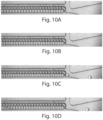
- FIG. 10 A non-limiting example may be seen in Fig. 10 .
- a plurality of droplets is contained within a collection chamber.
- the horizontal outlet on the right of the collection chamber has a lower flow resistance than other outlets.
- the pressure is increased, slightly deforming the droplets.
- Figs. 10C and 10D the droplets begin to leave the collection chamber through the horizontal outlet due to the increase in applied pressure.
- actuation channels fluidly connecting to different collection chambers may be fluidly connected to each other.
- droplets from multiple collection chambers may be released, e.g., simultaneously or sequentially, depending on when fluid enters each of the collection chambers, for instance, from actuation channels.
- a sequential release system is shown in Fig. 4A .
- a series of collection chambers 51, 52, 53, ... are each connected to separate actuation channels 41, 42 ,43, ....
- the collection chambers are linearly arrayed; however, this is by way of example only, and in other embodiments, one or more (or all) of the collection chambers may be able to contain more than one droplet or other entity (and they need not necessarily all collect the same number of such entities), and the collection chambers may be arranged in any suitable configuration, e.g., in series, parallel, or any other suitable configuration.
- the collection chambers as shown in this example, are in fluid communication with a common channel 60. A fluid entering into common channel 60 can pass through each of the separate actuation channels to cause release of droplets or other entities from their collection chambers, e.g., in a controlled manner.
- actuation channels 41, 42, 43, ... are not all the same length.
- the different lengths may cause fluid entering from common channel 60 to reach each of collection chambers 51, 52, 53, ... at different points in time, thereby allowing sequential release of droplets or other entities from collection chambers 51, 52, 53, ... at different times, rather than simultaneously, based for example, on when the entering fluid reaches each of the collection chambers.
- An example of the sequential release of droplets from such a system is shown in Figs. 5A-5D , where a plurality of collection chambers contains droplets that are released in left-to-right fashion, progressing from Fig. 5A to Fig. 5D .
- FIG. 4B A similar system is shown in Fig. 4B .
- the collection chambers are not necessarily connected using bypass channels, such as those previously discussed above.
- fluid enters from inlet 70.
- the flow or hydrodynamic resistance in outlet 80 may be greater than the flow resistance through actuation channels 41, 42, 43, 44, and 45, such that fluid flows preferentially into collection chambers 51, 52, 53, 54, and 55 rather than through outlet 80, e.g., such that droplets or other entities contained within the fluid enter collection chambers.
- Actuation channels 41, 42, 43, 44, and 45 may act as fluid outlets from collection chambers 51, 52, 53, 54, and 55, but may be sized or otherwise prevent droplets or other entities from exiting therethrough.
- actuation channels 41, 42, 43, 44, and 45 may have different flow resistance, such that fluid preferentially flows in collection chamber 51 relative to collection chamber 52, and collection chamber 52 relative to collection chamber 53, etc. This may be useful, e.g., to allow the collection chambers to fill sequentially (although in other embodiments, the collection chambers may also be filled randomly, e.g., if the resistances are substantially the same). Droplets or other entities may also be released from the collection chambers, e.g., by flowing a fluid through common channel 60 back into the collection chambers.
- droplets or other entities within the collection chamber may exit via the actuation channel.
- an actuation channel may be prevented from allowing fluid flow therethrough, e.g., through use of a valve that is partially or completely closed. Upon opening of the valve, droplets or other entities may flow through the actuation channel and thereby be released from the collection chamber.
- more than one collection chamber may be present within a device.
- the collection chambers may be arranged in any suitable configuration. For example, they may be arranged in a relatively linear fashion, such as is shown in Fig. 4A , or in a 2-dimensional matrix, such as is shown in Fig. 6A (and expanded in Fig. 6B ). Such collection chambers may be arranged, for example, in series, parallel, or in any other suitable configuration. In some embodiments, for instance, a plurality of collection chambers may be in relatively close proximity to each other. For instance, the collection chambers may be arranged such that a branch point for one (e.g., branching between a collection chamber and a bypass channel) is also the branch point for a following collection chamber. Non-limiting examples of such configurations can be seen, for example, in Figs. 4 or 6B .
- a microfluidic device as discussed herein may contain any number of collection chambers.
- the collection chambers may be able to independently collect the same, or different, numbers of droplets or other entities.
- the collection chambers of a microfluidic device may be connected to a common inlet and/or a common outlet, and/or to more than one inlet and/or more than one outlet.
- Any number of suitable collection chambers may be present, and they may be positioned in any suitable location within the device, e.g., in a regular or irregular array, in 1-, 2-, or 3 dimensions.
- the collection chambers may be arranged in a rectangular or other orderly array (e.g., a 1-dimensional array), e.g., to facilitate image acquisition of the collection chambers (e.g., by microscopy, well plate readers, or the like) and/or the droplets or other entities therein.
- a rectangular or other orderly array e.g., a 1-dimensional array
- the entities to be contained within collection chambers may be droplets, e.g., of a first fluid contained within a second or carrying fluid.
- the first fluid and the second fluid are substantially immiscible.
- a droplet is not necessarily spherical, but may assume other shapes as well, for example, depending on the external environment.
- the average or characteristic diameter of a droplet, in a non-spherical droplet may be taken as the diameter of a perfect mathematical sphere having the same volume as the non-spherical droplet.
- the droplets may be created using any suitable technique, as discussed herein.
- the droplet may be an isolated portion of a first fluid that is completely surrounded by a second fluid, or the droplet may have a size or cross-sectional area that is smaller than the channel containing the droplet. In other cases, however, the droplet may be somewhat larger, and may be deformed or "squashed" within a channel of the device.
- a "fluid” is given its ordinary meaning, i.e., a liquid or a gas.
- a fluid cannot maintain a defined shape and will flow during an observable time frame to fill the container in which it is put.
- the fluid may have any suitable viscosity that permits flow. If two or more fluids are present, each fluid may be independently selected among essentially any fluids (liquids, gases, and the like) by those of ordinary skill in the art.
- the droplets and the fluid containing the droplets are substantially immiscible. In some cases, however, they may be miscible.
- a hydrophilic liquid may be suspended in a hydrophobic liquid
- a hydrophobic liquid may be suspended in a hydrophilic liquid
- a gas bubble may be suspended in a liquid
- a hydrophobic liquid and a hydrophilic liquid are substantially immiscible with respect to each other, where the hydrophilic liquid has a greater affinity to water than does the hydrophobic liquid.
- hydrophilic liquids include, but are not limited to, water and other aqueous solutions comprising water, such as cell or biological media, ethanol, salt solutions, etc.
- hydrophobic liquids include, but are not limited to, oils such as hydrocarbons, silicon oils, fluorocarbon oils, organic solvents etc.
- two fluids can be selected to be substantially immiscible within the time frame of formation of the droplets.
- suitable substantially miscible or substantially immiscible fluids using contact angle measurements or the like, to carry out the techniques of the invention.
- the droplets may be stabilized using one or more surfactants.
- immiscibility may be determined at equilibrium via phase separation or other suitable behavior, e.g., for two fluids that are exposed to each other under room temperature and normal pressure conditions (25 °C and 1 atm) and left undistributed for at least about a day.
- the carrier fluid is aqueous (e.g., a "water” phase)
- the fluid forming the droplets may be a non-aqueous fluid that is substantially immiscible within the aqueous fluid (e.g., an "oil” phase), or vice versa.
- the "water” phase is not limited to only pure water, but may be any fluid miscible in water, and/or the fluid may be water but contain other substances dissolved or suspended therein, etc.
- the "oil” phase need not be a hydrocarbon oil, but may be any fluid that is substantially immiscible in water. Accordingly, the terms “oil” and “water” are used as terms of convenience, as is typically understood by those of ordinary skill in the art.
- the first droplets and/or the second droplets are stabilized using a surfactant.
- the surfactant is present at the interface between the fluid contained within a droplet and the liquid surrounding the droplet.
- the surfactant has a relatively hydrophilic ("head") region and a relatively hydrophobic ("tail") region.
- the surfactant may have more than one relatively hydrophilic region and/or more than one relatively hydrophobic region.
- the surfactant may be positioned at the interface and oriented such that the hydrophilic region is directed to the relatively hydrophilic fluid and the hydrophobic region is directed to the relatively hydrophobic fluid, thereby stabilizing the droplet within the liquid.
- droplets directly physically contacting each other within a liquid may be unable to coalesce together to form a single, combined droplet, when in the absence of the surfactant, the droplets would otherwise coalesce together into a combined droplet, e.g., such that the fluids within the droplet are able to mix and/or such that the droplets can no longer be identified or distinguished as two separate droplets with a discrete interface between the droplets.
- the first and second droplets may have the same surfactant, or different surfactants in some cases. Any of a wide variety of surfactants may be used, and such surfactants are commonly known to those of ordinary skill in the art and can be readily obtained commercially. Examples of surfactants may be found in, e.g., C. Holtze, et al., "Biocompatible Surfactants for Water-in-Fluorocarbon Emulsions," Lab Chip, 8(10): 1632-9, 2008 ; J. Clausell-Tormos, et al., "Droplet-Based Microfluidic Platforms for the Encapsulation and Screening of Mammalian Cells and Multicellular Organisms," Chem.
- Carrier fluids can be hydrophilic (e.g., aqueous) or hydrophobic (e.g., an oil), and may be chosen depending on the type of droplet being formed (e.g., aqueous or oil-based) and the type of process occurring in the droplet (e.g., a chemical reaction).
- a carrier fluid may comprise a fluorocarbon.
- the carrier fluid is immiscible with the fluid in the droplet. In other embodiments, the carrier fluid is slightly miscible with the fluid in the droplet.
- a hydrophobic carrier fluid which is immiscible with the aqueous fluid defining the droplet, is slightly water soluble.
- oils such as PDMS and poly(trifluoropropylmethysiloxane) are slightly water soluble.
- the droplets may have an average or characteristic diameter of less than about 1 mm, less than about 500 micrometers, less than about 300 micrometers, less than about 200 micrometers, less than about 100 micrometers, less than about 75 micrometers, less than about 50 micrometers, less than about 30 micrometers, less than about 25 micrometers, less than about 20 micrometers, less than about 15 micrometers, less than about 10 micrometers, less than about 5 micrometers, less than about 3 micrometers, less than about 2 micrometers, less than about 1 micrometer, less than about 500 nm, less than about 300 nm, less than about 100 nm, or less than about 50 nm.
- the average diameter of the droplets may also be at least about 30 nm, at least about 50 nm, at least about 100 nm, at least about 300 nm, at least about 500 nm, at least about 1 micrometer, at least about 2 micrometers, at least about 3 micrometers, at least about 5 micrometers, at least about 10 micrometers, at least about 15 micrometers, or at least about 20 micrometers in certain cases. Combinations of any of the above are also possible.
- the "average diameter" of a population of droplets may be taken as the arithmetic average of the diameters of the droplets.
- the fluidic droplets may be substantially monodisperse.
- the fluidic droplets may have a distribution in diameters such that no more than about 5%, no more than about 2%, or no more than about 1% of the droplets have a diameter less than about 90% (or less than about 95%, or less than about 99%) and/or greater than about 110% (or greater than about 105%, or greater than about 101%) of the overall average diameter of the plurality of droplets.
- the fluidic droplets are polydisperse.
- a droplet may contain a species such as a chemical, biochemical, or biological entity, a cell, a particle, a bead, gases, molecules, a pharmaceutical agent, a drug, DNA, RNA, proteins, a fragrance, a reactive agent, a biocide, a fungicide, a pesticide, a preservative, or the like.
- the species can be any substance that can be contained in a fluid and can be differentiated from the fluid containing the species.
- the species may be dissolved or suspended in the fluid.
- the species may be present in one or more of the fluids. If the fluids contain droplets, the species can be present in some or all of the droplets.
- species that may be present include, for example, biochemical species such as nucleic acids such as siRNA, RNAi and DNA, proteins, peptides, or enzymes. Still other examples of species include, but are not limited to, nanoparticles, quantum dots, fragrances, proteins, indicators, dyes, fluorescent species, chemicals, or the like.
- the species may be a drug, pharmaceutical agent, or other species that has a physiological effect when ingested or otherwise introduced into the body, e.g., to treat a disease, relieve a symptom, or the like.
- the drug may be a small-molecule drug, e.g., having a molecular weight of less than about 2000 Da, less than about 1500 Da, less than about 1000 Da, or less than about 500 Da.
- the collection chambers may be used to collect particles, e.g., in addition to and/or instead of droplets.
- the particles may be, for example, metal, glass, polymeric, gel, or the like.
- the particles may be monodisperse, and/or the particles may be spherical, or non-spherical in certain cases. In some cases, some or all of the particles may be microparticles and/or nanoparticles.
- Microparticles generally have an average diameter of less than about 1 mm (e.g., such that the average diameter of the particles is typically measured in micrometers), while nanoparticles generally have an average diameter of less than about 1 micrometer (e.g., such that the average diameter of the particles is typically measured in nanometers). In some cases, the nanoparticles may have an average diameter of less than about 100 nm.
- the particles may have a distribution in diameters such that at least about 50%, at least about 60%, at least about 70%, about 80%, at least about 85%, at least about 90%, at least about 95%, at least about 97%, or at least about 99% of the droplets have a diameter that is no more than about 10% different, no more than about 7% different, no more than about 5% different, no more than about 4% different, no more than about 3% different, no more than about 2% different, or no more than about 1% different from the average diameter of the particles.
- the average diameter of the particles is less than about 1 mm, less than about 500 micrometers, less than about 300 micrometers, less than about 200 micrometers, less than about 100 micrometers, less than about 75 micrometers, less than about 50 micrometers, less than about 30 micrometers, less than about 25 micrometers, less than about 20 micrometers, less than about 15 micrometers, less than about 10 micrometers, less than about 5 micrometers, less than about 3 micrometers, less than about 2 micrometers, less than about 1 micrometer, less than about 500 nm, less than about 300 nm, less than about 100 nm, or less than about 50 nm.
- the average diameter of the particles may also be at least about 30 nm, at least about 50 nm, at least about 100 nm, at least about 300 nm, at least about 500 nm, at least about 1 micrometer, at least about 2 micrometers, at least about 3 micrometers, at least about 5 micrometers, at least about 10 micrometers, at least about 15 micrometers, or at least about 20 micrometers in certain cases. Combinations of these are also possible in some embodiments.
- the particles may also be spherical or non-spherical, and the average or characteristic diameter of a particle may be taken as the dimeter of a perfect sphere having the same volume as the particle.
- Fluids may be delivered into the device (e.g., into one or more channels) from one or more fluid sources.
- Any suitable source of fluid can be used, and in some cases, more than one source of fluid is used.
- a pump, gravity, capillary action, surface tension, electroosmosis, centrifugal forces, etc. may be used to deliver a fluid from a fluid source to the device.
- a vacuum e.g., from a vacuum pump or other suitable vacuum source
- Non-limiting examples of pumps include syringe pumps, peristaltic pumps, pressurized fluid sources, or the like.
- the device can have any number of fluid sources associated with it, for example, 1, 2, 3, 4, 5, 6, 7, 8, 9, 10, etc., or more fluid sources.
- the fluid sources need not be used to deliver fluid into the same channel, e.g., a first fluid source can deliver a first fluid to a first channel while a second fluid source can deliver a second fluid to a second channel, etc.
- a variety of materials and methods, according to certain aspects of the invention, can be used to form devices or components such as those described herein, e.g., channels such as microfluidic channels, chambers, etc.
- various devices or components can be formed from solid materials, in which the channels can be formed via machining or micromachining, 3D-printing, film deposition processes such as spin coating and chemical vapor deposition, physical vapor deposition, laser fabrication, photolithographic techniques, etching methods including wet chemical or plasma processes, electrodeposition, 3D-printing, hot embossing, lamination, laser cutting, and the like. See, for example, Scientific American, 248:44-55, 1983 (Angell , et al ).
- various structures or components of the devices described herein can be formed of materials such as glass, metals, polymers, etc.
- a non-limiting example of a polymer is an elastomeric polymer such as polydimethylsiloxane ("PDMS”), polytetrafluoroethylene (“PTFE” or Teflon ® ), or the like.
- a channel such as a microfluidic channel may be implemented by fabricating the fluidic system separately using PDMS or other soft lithography techniques (details of soft lithography techniques suitable for this embodiment are discussed in the references entitled " Soft Lithography,” by Younan Xia and George M. Whitesides, published in the Annual Review of Material Science, 1998, Vol.
- polymers include, but are not limited to, polyethylene terephthalate (PET), polyacrylate, polymethacrylate, polycarbonate, polystyrene, polyethylene, polypropylene, polyvinylchloride, cyclic olefin copolymer (COC), polytetrafluoroethylene, a fluorinated polymer, a silicone such as polydimethylsiloxane, polyvinylidene chloride, bis-benzocyclobutene (“BCB”), a polyimide, a fluorinated derivative of a polyimide, or the like. Combinations, copolymers, or blends involving polymers including those described above are also envisioned.
- the device may also be formed from composite materials, for example, a composite of a polymer and a semiconductor material.
- various structures or components of the device are fabricated from polymeric and/or flexible and/or elastomeric materials, and can be conveniently formed of a hardenable fluid, facilitating fabrication via molding (e.g. replica molding, injection molding, cast molding, etc.).
- the hardenable fluid can be essentially any fluid that can be induced to solidify, or that spontaneously solidifies, into a solid capable of containing and/or transporting fluids contemplated for use in and with the fluidic network.
- the hardenable fluid comprises a polymeric liquid or a liquid polymeric precursor (i.e. a "prepolymer").
- Suitable polymeric liquids can include, for example, thermoplastic polymers, thermoset polymers, waxes, metals, or mixtures or composites thereof heated above their melting point.
- a suitable polymeric liquid may include a solution of one or more polymers in a suitable solvent, which solution forms a solid polymeric material upon removal of the solvent, for example, by evaporation.
- Such polymeric materials which can be solidified from, for example, a melt state or by solvent evaporation, are well known to those of ordinary skill in the art.
- a variety of polymeric materials, many of which are elastomeric, are suitable, and are also suitable for forming molds or mold masters, for embodiments where one or both of the mold masters is composed of an elastomeric material.
- a non-limiting list of examples of such polymers includes polymers of the general classes of silicone polymers, epoxy polymers, thiol-enes, and acrylate polymers.
- Epoxy polymers are characterized by the presence of a three-membered cyclic ether group commonly referred to as an epoxy group, 1,2-epoxide, or oxirane.
- diglycidyl ethers of bisphenol A can be used, in addition to compounds based on aromatic amine, triazine, and cycloaliphatic backbones.
- Another example includes the well-known Novolac polymers.
- Non-limiting examples of silicone elastomers suitable for use according to the invention include those formed from precursors including the chlorosilanes such as methylchlorosilanes, ethylchlorosilanes, phenylchlorosilanes, etc.
- Silicone polymers are used in certain embodiments, for example, the silicone elastomer polydimethylsiloxane.
- Non-limiting examples of PDMS polymers include those sold under the trademark Sylgard by Dow Chemical Co., Midland, MI, and particularly Sylgard 182, Sylgard 184, and Sylgard 186.
- Silicone polymers including PDMS have several beneficial properties simplifying fabrication of various structures of the invention. For instance, such materials are inexpensive, readily available, and can be solidified from a prepolymeric liquid via curing with heat.
- PDMSs are typically curable by exposure of the prepolymeric liquid to temperatures of about, for example, about 65 °C to about 75 °C for exposure times of, for example, at least about an hour.
- silicone polymers such as PDMS
- PDMS polymethyl methacrylate copolymer
- flexible (e.g., elastomeric) molds or masters can be advantageous in this regard.
- One advantage of forming structures such as microfluidic structures or channels from silicone polymers, such as PDMS, is the ability of such polymers to be oxidized, for example by exposure to an oxygen-containing plasma such as an air plasma, so that the oxidized structures contain, at their surface, chemical groups capable of cross-linking to other oxidized silicone polymer surfaces or to the oxidized surfaces of a variety of other polymeric and non-polymeric materials.
- structures can be fabricated and then oxidized and essentially irreversibly sealed to other silicone polymer surfaces, or to the surfaces of other substrates reactive with the oxidized silicone polymer surfaces, without the need for separate adhesives or other sealing means.
- oxidized silicone such as oxidized PDMS can also be sealed irreversibly to a range of oxidized materials other than itself including, for example, glass, silicon, silicon oxide, quartz, silicon nitride, polyethylene, polystyrene, glassy carbon, and epoxy polymers, which have been oxidized in a similar fashion to the PDMS surface (for example, via exposure to an oxygen-containing plasma).
- Oxidation and sealing methods useful in the context of the present invention, as well as overall molding techniques, are described in the art, for example, in an article entitled " Rapid Prototyping of Microfluidic Systems and Polydimethylsiloxane," Anal. Chem., 70:474-480, 1998 (Duffy et al .).
- channels or other structures can be much more hydrophilic than the surfaces of typical elastomeric polymers (where a hydrophilic interior surface is desired).
- Such hydrophilic channel surfaces can thus be more easily filled and wetted with aqueous solutions than can structures comprised of typical, unoxidized elastomeric polymers or other hydrophobic materials.
- such devices may be produced using more than one layer or substrate, e.g., more than one layer of PDMS.
- devices having channels with multiple heights and/or devices having interfaces positioned such as described herein may be produced using more than one layer or substrate, which may then be assembled or bonded together, e.g., using plasma bonding, to produce the final device.
- a device as discussed herein may be molded from masters comprising two or more layers of photoresists, e.g., where two PDMS molds are then bonded together by activating the PDMS surfaces using O 2 plasma or other suitable techniques.
- the masters from which the PDMS device is cast may contain one or multiple layers of photoresist, e.g., to form a 3D device.
- one or more of the layers may have one or more mating protrusions and/or indentations which are aligned to properly align the layers, e.g., in a lock-and-key fashion.
- a first layer may have a protrusion (having any suitable shape) and a second layer may have a corresponding indentation which can receive the protrusion, thereby causing the two layers to become properly aligned with respect to each other.
- a device (or at least a portion of a device) may be prepared by preparing a mold (e.g., via 3D printing or other suitable fabrication techniques), then forming a microfluidic device using the mold, e.g., by hardening a polymer around the mold, then removing the mold to produce the microfluidic device.
- a mold e.g., via 3D printing or other suitable fabrication techniques
- suitable molds e.g., by hardening a polymer around the mold, then removing the mold to produce the microfluidic device.
- one or more walls or portions of a channel may be coated, e.g., with a coating material, including photoactive coating materials.
- each of the microfluidic channels at the common junction may have substantially the same hydrophobicity, although in other embodiments, various channels may have different hydrophobicities.
- a first channel (or set of channels) at a common junction may exhibit a first hydrophobicity, while the other channels may exhibit a second hydrophobicity different from the first hydrophobicity, e.g., exhibiting a hydrophobicity that is greater or less than the first hydrophobicity.
- Examples of systems and methods for coating microfluidic channels, for example, with sol-gel coatings may be seen in International Patent Application No.
- PCT/US2009/000850 filed February 11, 2009, entitled “Surfaces, Including Microfluidic Channels, With Controlled Wetting Properties,” by Abate, et al. , published as WO 2009/120254 on October 1, 2009 , and International Patent Application No. PCT/US2008/009477, filed August 7, 2008, entitled “Metal Oxide Coating on Surfaces,” by Weitz, et al ., published as WO 2009/020633 on February 12, 2009 .
- Other examples of coatings include polymers, metals, silanes, or ceramic coatings, e.g., using techniques known to those of ordinary skill in the art.
- some or all of the channels may be coated, or otherwise treated such that some or all of the channels, including the inlet and daughter channels, each have substantially the same hydrophilicity.
- the coating materials can be used in certain instances to control and/or alter the hydrophobicity of the wall of a channel.
- a sol-gel is provided that can be formed as a coating on a substrate such as the wall of a channel such as a microfluidic channel. One or more portions of the sol-gel can be reacted to alter its hydrophobicity, in some cases.
- a portion of the sol-gel may be exposed to light, such as ultraviolet light, which can be used to induce a chemical reaction in the sol-gel that alters its hydrophobicity.
- the sol-gel may include a photoinitiator which, upon exposure to light, produces radicals.
- the photoinitiator is conjugated to a silane or other material within the sol-gel.
- the radicals so produced may be used to cause a condensation or polymerization reaction to occur on the surface of the sol-gel, thus altering the hydrophobicity of the surface.
- various portions may be reacted or left unreacted, e.g., by controlling exposure to light (for instance, using a mask).
- various embodiments of the present invention relate to droplets of fluid.
- the droplets may be of substantially the same shape and/or size, or of different shapes and/or sizes, depending on the particular application. It should be noted that a droplet is not necessarily spherical, but may assume other shapes as well, for example, depending on the external environment.
- a droplet in some cases, may have a cross-sectional dimension that is smaller than the channel containing the droplet, although in other cases, the droplet may completely fill a cross-sectional portion of the channel.
- the systems and methods described herein may include one or more microfluidic components, for example, one or more microfluidic channels.
- Microfluidic refers to a device, apparatus or system including at least one fluid channel having a cross-sectional dimension of less than 1 mm. In some cases, the channel may have a ratio of length to largest cross-sectional dimension of at least 3:1.
- a "microfluidic channel,” as used herein, is a channel meeting these criteria. The “cross-sectional dimension" of the channel is measured perpendicular to the direction of fluid flow within the channel.
- some or all of the fluid channels in microfluidic embodiments of the invention may have maximum cross-sectional dimensions less than 2 mm, and in certain cases, less than 1 mm.
- all fluid channels containing embodiments of the invention are microfluidic or have a largest cross sectional dimension of no more than 2 mm or 1 mm.
- the fluid channels may be formed in part by a single component (e.g. an etched substrate or molded unit). Of course, larger channels, tubes, chambers, reservoirs, etc. can be used to store fluids and/or deliver fluids.
- the maximum cross-sectional dimension of the channel(s) containing embodiments of the invention is less than 500 microns, less than 200 microns, less than 100 microns, less than 50 microns, or less than 25 microns.
- a channel can have any cross-sectional shape (circular, oval, triangular, irregular, square or rectangular, or the like) and can be covered or uncovered. In embodiments where it is completely covered, at least one portion of the channel can have a cross-section that is completely enclosed, or the entire channel may be completely enclosed along its entire length with the exception of its inlet(s) and/or outlet(s).
- a channel may also have an aspect ratio (length to average cross sectional dimension) of at least 2:1, more typically at least 3:1, 5:1, 10:1, 15:1, 20:1, or more.
- An open channel generally will include characteristics that facilitate control over fluid transport, e.g., structural characteristics (an elongated indentation) and/or physical or chemical characteristics (hydrophobicity vs.
- hydrophilicity or other characteristics that can exert a force (e.g., a containing force) on a fluid.
- the fluid within the channel may partially or completely fill the channel.
- the fluid may be held within the channel, for example, using surface tension (i.e., a concave or convex meniscus).
- the channel may be of any size, for example, having a largest dimension perpendicular to fluid flow of less than about 5 mm or 2 mm, or less than about 1 mm, or less than about 500 microns, less than about 200 microns, less than about 100 microns, less than about 60 microns, less than about 50 microns, less than about 40 microns, less than about 30 microns, less than about 25 microns, less than about 10 microns, less than about 3 microns, less than about 1 micron, less than about 300 nm, less than about 100 nm, less than about 30 nm, or less than about 10 nm.
- the dimensions of the channel may be chosen such that fluid is able to freely flow through the article or substrate.
- the dimensions of the channel may also be chosen, for example, to allow a certain volumetric or linear flowrate of fluid in the channel.
- the number of channels and the shape of the channels can be varied by any method known to those of ordinary skill in the art. In some cases, more than one channel or capillary may be used. For example, two or more channels may be used, where they are positioned inside each other, positioned adjacent to each other, positioned to intersect with each other, etc.
- a reference to "A and/or B", when used in conjunction with open-ended language such as “comprising” can refer, in one embodiment, to A only (optionally including elements other than B); in another embodiment, to B only (optionally including elements other than A); in yet another embodiment, to both A and B (optionally including other elements); etc.
- the phrase "at least one,” in reference to a list of one or more elements, should be understood to mean at least one element selected from any one or more of the elements in the list of elements, but not necessarily including at least one of each and every element specifically listed within the list of elements and not excluding any combinations of elements in the list of elements.
- This definition also allows that elements may optionally be present other than the elements specifically identified within the list of elements to which the phrase "at least one" refers, whether related or unrelated to those elements specifically identified.
- At least one of A and B can refer, in one embodiment, to at least one, optionally including more than one, A, with no B present (and optionally including elements other than B); in another embodiment, to at least one, optionally including more than one, B, with no A present (and optionally including elements other than A); in yet another embodiment, to at least one, optionally including more than one, A, and at least one, optionally including more than one, B (and optionally including other elements); etc.
Landscapes
- Chemical & Material Sciences (AREA)
- Health & Medical Sciences (AREA)
- Clinical Laboratory Science (AREA)
- Chemical Kinetics & Catalysis (AREA)
- Dispersion Chemistry (AREA)
- Analytical Chemistry (AREA)
- General Health & Medical Sciences (AREA)
- Hematology (AREA)
- Life Sciences & Earth Sciences (AREA)
- Molecular Biology (AREA)
- Physics & Mathematics (AREA)
- Fluid Mechanics (AREA)
- Apparatus Associated With Microorganisms And Enzymes (AREA)
- Physical Or Chemical Processes And Apparatus (AREA)
- Automatic Analysis And Handling Materials Therefor (AREA)
- Sampling And Sample Adjustment (AREA)
Claims (5)
- Appareil de collecte d'entités microfluidiques, comprenant :un premier canal microfluidique (21) et un second canal microfluidique (22), chacun des canaux reliant fluidiquement un premier emplacement (11) et un second emplacement (12), dans lequel le fluide peut s'écouler soit à travers le premier canal microfluidique (21), soit à travers le second canal microfluidique (22),dans lequel le premier canal microfluidique (21) comprend une chambre de collecte (30) présentant une entrée (31) et deux sorties ou plus (32, 33, 34, 35), chacune de l'entrée (31) et des deux sorties ou plus (32, 33, 34, 35) présentant une section transversale, la section transversale de l'entrée (31) étant plus grande que chacune des sections transversales de chacune des sorties (32, 33, 34, 35), moyennant quoi la chambre de collecte (30) est en mesure de collecter des entités microfluidiques ayant une section transversale supérieure aux sections transversales de chacune des sorties (32, 33, 34, 35) et inférieure à la section transversale de l'entrée (31),dans lequel le premier canal microfluidique (21), en l'absence d'entités, présente une résistance à l'écoulement qui est inférieure à une résistance à l'écoulement du second canal microfluidique (22), et lorsque le premier canal microfluidique (21) contient une ou plusieurs entités microfluidiques, présente une résistance à l'écoulement qui est supérieure à une résistance à l'écoulement du second canal microfluidique (22), etdans lequel le premier canal microfluidique (21) comprend en outre un canal d'actionnement (40) de sorte que, lorsque le fluide s'écoule à travers ledit canal d'actionnement (40), le fluide soit en mesure d'amener les entités dans la chambre de collecte (30) à sortir de la chambre de collecte (30) par l'entrée (31).
- Appareil selon la revendication 1, dans lequel les sorties (32, 33, 34, 35) sont espacées de sorte que les entités microfluidiques d'un diamètre moyen prédéterminé pénétrant par l'entrée (31) et pouvant être collectées par la chambre de collecte (30) soient en mesure de bloquer uniquement une sortie (32, 33, 34, 35) dans la chambre de collecte (30) à la fois, le diamètre moyen des entités microfluidiques étant des gouttelettes microfluidiques, des particules ou des particules de gel étant inférieur à 1 mm.
- Appareil selon l'une quelconque des revendications précédentes, dans lequel les sorties (32, 33, 34, 35) sont espacées d'une distance qui est 75 % de la largeur de l'entrée (31).
- Appareil selon l'une quelconque des revendications précédentes, dans lequel la chambre de collecte (30) est droite.
- Appareil selon la revendication 4, dans lequel la chambre de collecte (30) est destinée à collecter les entités microfluidiques en file indienne, les entités microfluidiques étant des gouttelettes ou des particules, dans lequel les gouttelettes ou les particules ont un diamètre moyen de préférence inférieur à 1 mm.
Applications Claiming Priority (2)
| Application Number | Priority Date | Filing Date | Title |
|---|---|---|---|
| US201662323544P | 2016-04-15 | 2016-04-15 | |
| PCT/US2017/027545 WO2017180949A1 (fr) | 2016-04-15 | 2017-04-14 | Systèmes et procédés permettant la collecte de gouttelettes et/ou d'autres entités |
Publications (4)
| Publication Number | Publication Date |
|---|---|
| EP3442707A1 EP3442707A1 (fr) | 2019-02-20 |
| EP3442707A4 EP3442707A4 (fr) | 2019-12-04 |
| EP3442707B1 true EP3442707B1 (fr) | 2023-10-04 |
| EP3442707C0 EP3442707C0 (fr) | 2023-10-04 |
Family
ID=60041927
Family Applications (1)
| Application Number | Title | Priority Date | Filing Date |
|---|---|---|---|
| EP17783188.0A Active EP3442707B1 (fr) | 2016-04-15 | 2017-04-14 | Systèmes permettant la collecte de gouttelettes et/ou d'autres entités |
Country Status (7)
| Country | Link |
|---|---|
| US (1) | US11925933B2 (fr) |
| EP (1) | EP3442707B1 (fr) |
| JP (1) | JP2019514002A (fr) |
| CN (1) | CN109311010B (fr) |
| AU (1) | AU2017250269A1 (fr) |
| CA (1) | CA3020913C (fr) |
| WO (1) | WO2017180949A1 (fr) |
Families Citing this family (64)
| Publication number | Priority date | Publication date | Assignee | Title |
|---|---|---|---|---|
| CA3216609C (fr) | 2012-08-14 | 2024-05-14 | 10X Genomics, Inc. | Compositions de microcapsule et procedes |
| US10323279B2 (en) | 2012-08-14 | 2019-06-18 | 10X Genomics, Inc. | Methods and systems for processing polynucleotides |
| US10395758B2 (en) | 2013-08-30 | 2019-08-27 | 10X Genomics, Inc. | Sequencing methods |
| US9824068B2 (en) | 2013-12-16 | 2017-11-21 | 10X Genomics, Inc. | Methods and apparatus for sorting data |
| MX2016016904A (es) | 2014-06-26 | 2017-03-27 | 10X Genomics Inc | Analisis de secuencias de acidos nucleicos. |
| CN113249435B (zh) | 2014-06-26 | 2024-09-03 | 10X基因组学有限公司 | 分析来自单个细胞或细胞群体的核酸的方法 |
| US12312640B2 (en) | 2014-06-26 | 2025-05-27 | 10X Genomics, Inc. | Analysis of nucleic acid sequences |
| SG11201705615UA (en) | 2015-01-12 | 2017-08-30 | 10X Genomics Inc | Processes and systems for preparing nucleic acid sequencing libraries and libraries prepared using same |
| US12290811B2 (en) | 2015-01-23 | 2025-05-06 | Unchained Labs | Microfluidic serial dilution platform based well-plate using an oil-free immiscible phase driven by manual or electronic pipettors |
| US11371094B2 (en) | 2015-11-19 | 2022-06-28 | 10X Genomics, Inc. | Systems and methods for nucleic acid processing using degenerate nucleotides |
| US10815525B2 (en) | 2016-12-22 | 2020-10-27 | 10X Genomics, Inc. | Methods and systems for processing polynucleotides |
| US10550429B2 (en) | 2016-12-22 | 2020-02-04 | 10X Genomics, Inc. | Methods and systems for processing polynucleotides |
| US12264411B2 (en) | 2017-01-30 | 2025-04-01 | 10X Genomics, Inc. | Methods and systems for analysis |
| CN110214186B (zh) | 2017-01-30 | 2023-11-24 | 10X基因组学有限公司 | 用于基于微滴的单细胞条形编码的方法和系统 |
| US10995333B2 (en) | 2017-02-06 | 2021-05-04 | 10X Genomics, Inc. | Systems and methods for nucleic acid preparation |
| WO2018200896A1 (fr) | 2017-04-28 | 2018-11-01 | Neofluidics, Llc | Dispositifs fluidiques à puits de réaction, et utilisations associés |
| US10544413B2 (en) | 2017-05-18 | 2020-01-28 | 10X Genomics, Inc. | Methods and systems for sorting droplets and beads |
| CN110945139B (zh) | 2017-05-18 | 2023-09-05 | 10X基因组学有限公司 | 用于分选液滴和珠的方法和系统 |
| EP3665262A4 (fr) | 2017-08-09 | 2021-09-01 | Neofluidics, LLC | Dispositifs et procédés pour essai biologique |
| US20190064173A1 (en) | 2017-08-22 | 2019-02-28 | 10X Genomics, Inc. | Methods of producing droplets including a particle and an analyte |
| US10837047B2 (en) | 2017-10-04 | 2020-11-17 | 10X Genomics, Inc. | Compositions, methods, and systems for bead formation using improved polymers |
| CN111886074A (zh) * | 2017-10-20 | 2020-11-03 | 杜克大学 | 用于高通量单细胞分析的设备,系统和方法 |
| WO2019083852A1 (fr) | 2017-10-26 | 2019-05-02 | 10X Genomics, Inc. | Réseaux de canaux microfluidiques pour partitionnement |
| CN114525273B (zh) | 2017-10-27 | 2025-01-28 | 10X基因组学有限公司 | 用于样品制备和分析的方法和系统 |
| JP7256198B2 (ja) | 2017-11-10 | 2023-04-11 | ネオフルーイディクス,リミティド ライアビリティ カンパニー | 液滴操作のための統合された流体回路およびデバイスならびにその方法 |
| EP3954782A1 (fr) | 2017-11-15 | 2022-02-16 | 10X Genomics, Inc. | Perles de gel fonctionnalisées |
| CN118818037A (zh) | 2017-12-12 | 2024-10-22 | 10X基因组学有限公司 | 用于单细胞处理的系统和方法 |
| CN118547046A (zh) | 2017-12-22 | 2024-08-27 | 10X基因组学有限公司 | 用于处理来自一个或多个细胞的核酸分子的系统和方法 |
| WO2019157529A1 (fr) | 2018-02-12 | 2019-08-15 | 10X Genomics, Inc. | Procédés de caractérisation d'analytes multiples à partir de cellules individuelles ou de populations cellulaires |
| US11639928B2 (en) | 2018-02-22 | 2023-05-02 | 10X Genomics, Inc. | Methods and systems for characterizing analytes from individual cells or cell populations |
| WO2019169028A1 (fr) | 2018-02-28 | 2019-09-06 | 10X Genomics, Inc. | Séquençage de transcriptomes par ligation aléatoire |
| WO2019183090A1 (fr) | 2018-03-20 | 2019-09-26 | The Trustees Of The University Of Pennsylvania | Dispositifs microfluidiques et procédés de surveillance de la biologie sanguine sous écoulement |
| WO2019217758A1 (fr) | 2018-05-10 | 2019-11-14 | 10X Genomics, Inc. | Procédés et systèmes de génération de banque moléculaire |
| US11932899B2 (en) | 2018-06-07 | 2024-03-19 | 10X Genomics, Inc. | Methods and systems for characterizing nucleic acid molecules |
| US11703427B2 (en) | 2018-06-25 | 2023-07-18 | 10X Genomics, Inc. | Methods and systems for cell and bead processing |
| US12188014B1 (en) | 2018-07-25 | 2025-01-07 | 10X Genomics, Inc. | Compositions and methods for nucleic acid processing using blocking agents |
| US20200032335A1 (en) | 2018-07-27 | 2020-01-30 | 10X Genomics, Inc. | Systems and methods for metabolome analysis |
| EP3830289B1 (fr) | 2018-08-03 | 2026-02-11 | 10X Genomics, Inc. | Procédés pour réduire au minimum un échange de codes à barres |
| US12065688B2 (en) | 2018-08-20 | 2024-08-20 | 10X Genomics, Inc. | Compositions and methods for cellular processing |
| WO2020041148A1 (fr) | 2018-08-20 | 2020-02-27 | 10X Genomics, Inc. | Procédés et systèmes pour la détection d'interactions protéine-adn à l'aide d'une ligature de proximité |
| US11998885B2 (en) | 2018-10-26 | 2024-06-04 | Unchained Labs | Fluidic devices with reaction wells and constriction channels and uses thereof |
| US11459607B1 (en) | 2018-12-10 | 2022-10-04 | 10X Genomics, Inc. | Systems and methods for processing-nucleic acid molecules from a single cell using sequential co-partitioning and composite barcodes |
| US12169198B2 (en) | 2019-01-08 | 2024-12-17 | 10X Genomics, Inc. | Systems and methods for sample analysis |
| US11845983B1 (en) | 2019-01-09 | 2023-12-19 | 10X Genomics, Inc. | Methods and systems for multiplexing of droplet based assays |
| US11851683B1 (en) | 2019-02-12 | 2023-12-26 | 10X Genomics, Inc. | Methods and systems for selective analysis of cellular samples |
| US12275993B2 (en) | 2019-02-12 | 2025-04-15 | 10X Genomics, Inc. | Analysis of nucleic acid sequences |
| WO2020167866A1 (fr) | 2019-02-12 | 2020-08-20 | 10X Genomics, Inc. | Systèmes et procédés pour le chargement de transposons |
| US12305239B2 (en) | 2019-02-12 | 2025-05-20 | 10X Genomics, Inc. | Analysis of nucleic acid sequences |
| WO2020167862A1 (fr) | 2019-02-12 | 2020-08-20 | 10X Genomics, Inc. | Systèmes et procédés pour le transfert de réactifs entre des gouttelettes |
| US11655499B1 (en) | 2019-02-25 | 2023-05-23 | 10X Genomics, Inc. | Detection of sequence elements in nucleic acid molecules |
| WO2020176882A1 (fr) | 2019-02-28 | 2020-09-03 | 10X Genomics, Inc. | Dispositifs, systèmes et procédés pour augmenter l'efficacité de formation de gouttelettes |
| CN113767178A (zh) | 2019-03-11 | 2021-12-07 | 10X基因组学有限公司 | 用于处理光学标签化珠粒的系统和方法 |
| CN113811619A (zh) | 2019-03-27 | 2021-12-17 | 10X基因组学有限公司 | 用于处理来自细胞的rna的系统和方法 |
| US12186751B2 (en) | 2019-06-28 | 2025-01-07 | 10X Genomics, Inc. | Devices and systems incorporating acoustic ordering and methods of use thereof |
| US12235262B1 (en) | 2019-09-09 | 2025-02-25 | 10X Genomics, Inc. | Methods and systems for single cell protein analysis |
| AU2020361681A1 (en) | 2019-10-10 | 2022-05-05 | 1859, Inc. | Methods and systems for microfluidic screening |
| US12059679B2 (en) | 2019-11-19 | 2024-08-13 | 10X Genomics, Inc. | Methods and devices for sorting droplets and particles |
| EP3838405A1 (fr) * | 2019-12-20 | 2021-06-23 | Imec VZW | Dispositif microfluidique |
| US11851700B1 (en) | 2020-05-13 | 2023-12-26 | 10X Genomics, Inc. | Methods, kits, and compositions for processing extracellular molecules |
| US12084715B1 (en) | 2020-11-05 | 2024-09-10 | 10X Genomics, Inc. | Methods and systems for reducing artifactual antisense products |
| US12480158B1 (en) | 2020-11-05 | 2025-11-25 | 10X Genomics, Inc. | Methods and systems for processing polynucleotides |
| US12398262B1 (en) | 2021-01-22 | 2025-08-26 | 10X Genomics, Inc. | Triblock copolymer-based cell stabilization and fixation system and methods of use thereof |
| CN120158497A (zh) | 2021-02-23 | 2025-06-17 | 10X基因组学有限公司 | 基于探针的核酸和蛋白质分析 |
| CN118201982A (zh) | 2022-08-18 | 2024-06-14 | 10X基因组学有限公司 | 具有含氟二醇添加剂的液滴形成装置和方法 |
Family Cites Families (22)
| Publication number | Priority date | Publication date | Assignee | Title |
|---|---|---|---|---|
| US5512131A (en) | 1993-10-04 | 1996-04-30 | President And Fellows Of Harvard College | Formation of microstamped patterns on surfaces and derivative articles |
| WO1996029629A2 (fr) | 1995-03-01 | 1996-09-26 | President And Fellows Of Harvard College | Procede d'impression par microcontact sur des surfaces et articles obtenus par ce procede |
| US6355198B1 (en) | 1996-03-15 | 2002-03-12 | President And Fellows Of Harvard College | Method of forming articles including waveguides via capillary micromolding and microtransfer molding |
| US6645432B1 (en) | 2000-05-25 | 2003-11-11 | President & Fellows Of Harvard College | Microfluidic systems including three-dimensionally arrayed channel networks |
| CA2480728A1 (fr) | 2002-04-01 | 2003-10-16 | Fluidigm Corporation | Systemes d'analyse de particules microfluidiques |
| JP2006507921A (ja) | 2002-06-28 | 2006-03-09 | プレジデント・アンド・フェロウズ・オブ・ハーバード・カレッジ | 流体分散のための方法および装置 |
| EP2127736A1 (fr) | 2003-04-10 | 2009-12-02 | The President and Fellows of Harvard College | Formation et régulation d'espèces fluidiques |
| CN104069784B (zh) | 2003-08-27 | 2017-01-11 | 哈佛大学 | 流体物种的电子控制 |
| EP1525916A1 (fr) * | 2003-10-23 | 2005-04-27 | F. Hoffmann-La Roche Ag | Dispositif de déclenchement d'écoulement |
| US7556776B2 (en) | 2005-09-08 | 2009-07-07 | President And Fellows Of Harvard College | Microfluidic manipulation of fluids and reactions |
| EP3536396B1 (fr) | 2006-08-07 | 2022-03-30 | The President and Fellows of Harvard College | Tensioactifs fluorocarbonés stabilisateurs d'émulsions |
| US8592221B2 (en) | 2007-04-19 | 2013-11-26 | Brandeis University | Manipulation of fluids, fluid components and reactions in microfluidic systems |
| US8883291B2 (en) | 2007-08-07 | 2014-11-11 | President And Fellows Of Harvard College | Metal oxide coating on surfaces |
| JP2011515236A (ja) | 2008-03-28 | 2011-05-19 | プレジデント アンド フェローズ オブ ハーバード カレッジ | 制御された濡れ特性を有するマイクロ流体チャネルを含む表面 |
| WO2009134395A2 (fr) | 2008-04-28 | 2009-11-05 | President And Fellows Of Harvard College | Dispositif microfluidique pour un stockage et un agencement bien défini de gouttelettes |
| US9358539B2 (en) | 2008-05-16 | 2016-06-07 | President And Fellows Of Harvard College | Valves and other flow control in fluidic systems including microfluidic systems |
| JP5841937B2 (ja) | 2009-06-26 | 2016-01-13 | プレジデント アンド フェローズ オブ ハーバード カレッジ | 流体注入 |
| KR20140063507A (ko) * | 2011-02-07 | 2014-05-27 | 프레지던트 앤드 펠로우즈 오브 하바드 칼리지 | 액적을 분할하기 위한 시스템 및 방법 |
| US9637718B2 (en) * | 2011-05-06 | 2017-05-02 | Texas Tech University System | Methods and devices to control fluid volumes, reagent and particle concentration in arrays of microfluidic drops |
| US9882197B2 (en) | 2013-10-11 | 2018-01-30 | Ec Power, Llc | All climate battery and manufacturing and using the same |
| US9757727B2 (en) * | 2014-05-29 | 2017-09-12 | Massachusetts Institute Of Technology | Hydrodynamic trap array |
| US10258987B2 (en) | 2014-06-26 | 2019-04-16 | President And Fellows Of Harvard College | Fluid infection using acoustic waves |
-
2017
- 2017-04-14 JP JP2018553886A patent/JP2019514002A/ja active Pending
- 2017-04-14 CN CN201780032681.1A patent/CN109311010B/zh active Active
- 2017-04-14 CA CA3020913A patent/CA3020913C/fr active Active
- 2017-04-14 AU AU2017250269A patent/AU2017250269A1/en not_active Abandoned
- 2017-04-14 EP EP17783188.0A patent/EP3442707B1/fr active Active
- 2017-04-14 US US16/093,178 patent/US11925933B2/en active Active
- 2017-04-14 WO PCT/US2017/027545 patent/WO2017180949A1/fr not_active Ceased
Also Published As
| Publication number | Publication date |
|---|---|
| AU2017250269A1 (en) | 2018-11-08 |
| US11925933B2 (en) | 2024-03-12 |
| CN109311010A (zh) | 2019-02-05 |
| EP3442707A1 (fr) | 2019-02-20 |
| WO2017180949A1 (fr) | 2017-10-19 |
| CA3020913A1 (fr) | 2017-10-19 |
| JP2019514002A (ja) | 2019-05-30 |
| EP3442707C0 (fr) | 2023-10-04 |
| US20190118182A1 (en) | 2019-04-25 |
| EP3442707A4 (fr) | 2019-12-04 |
| CN109311010B (zh) | 2022-05-17 |
| CA3020913C (fr) | 2024-01-02 |
Similar Documents
| Publication | Publication Date | Title |
|---|---|---|
| EP3442707B1 (fr) | Systèmes permettant la collecte de gouttelettes et/ou d'autres entités | |
| US20220331804A1 (en) | Systems and methods for droplet production and/or fluidic manipulation | |
| US20250033009A1 (en) | Scale-up of microfluidic devices | |
| EP2714254B1 (fr) | Génération d'émulsions et, notamment, d'émulsions multiples | |
| CN103347612B (zh) | 分裂液滴的系统和方法 | |
| WO2009029229A2 (fr) | Émulsions de ferrofluides, particules, ainsi que systèmes et procédés de production et d'utilisation de celles-ci | |
| WO2010104604A1 (fr) | Procédé destiné à la création contrôlée d'émulsions, comprenant des émulsions multiples | |
| CN102059162A (zh) | 微流体器件 | |
| WO2007089541A2 (fr) | Coalescence de gouttelettes fluidiques | |
| EP2996809A2 (fr) | Production rapide de gouttelettes | |
| US11141730B2 (en) | Coalescence of droplets | |
| HK40004350A (en) | Systems and methods for the collection of droplets and/or other entities | |
| HK40004350B (en) | Systems and methods for the collection of droplets and/or other entities | |
| HK1165359A (en) | Scale-up of flow-focusing microfluidic devices |
Legal Events
| Date | Code | Title | Description |
|---|---|---|---|
| STAA | Information on the status of an ep patent application or granted ep patent |
Free format text: STATUS: THE INTERNATIONAL PUBLICATION HAS BEEN MADE |
|
| PUAI | Public reference made under article 153(3) epc to a published international application that has entered the european phase |
Free format text: ORIGINAL CODE: 0009012 |
|
| STAA | Information on the status of an ep patent application or granted ep patent |
Free format text: STATUS: REQUEST FOR EXAMINATION WAS MADE |
|
| 17P | Request for examination filed |
Effective date: 20181108 |
|
| AK | Designated contracting states |
Kind code of ref document: A1 Designated state(s): AL AT BE BG CH CY CZ DE DK EE ES FI FR GB GR HR HU IE IS IT LI LT LU LV MC MK MT NL NO PL PT RO RS SE SI SK SM TR |
|
| AX | Request for extension of the european patent |
Extension state: BA ME |
|
| DAV | Request for validation of the european patent (deleted) | ||
| DAX | Request for extension of the european patent (deleted) | ||
| RIC1 | Information provided on ipc code assigned before grant |
Ipc: G01N 1/28 20060101ALI20190722BHEP Ipc: F17D 1/08 20060101ALI20190722BHEP Ipc: B01L 3/00 20060101AFI20190722BHEP |
|
| A4 | Supplementary search report drawn up and despatched |
Effective date: 20191105 |
|
| RIC1 | Information provided on ipc code assigned before grant |
Ipc: G01N 1/28 20060101ALI20191029BHEP Ipc: F17D 1/08 20060101ALI20191029BHEP Ipc: B01L 3/00 20060101AFI20191029BHEP |
|
| REG | Reference to a national code |
Ref country code: HK Ref legal event code: DE Ref document number: 40004350 Country of ref document: HK |
|
| STAA | Information on the status of an ep patent application or granted ep patent |
Free format text: STATUS: EXAMINATION IS IN PROGRESS |
|
| 17Q | First examination report despatched |
Effective date: 20200617 |
|
| GRAP | Despatch of communication of intention to grant a patent |
Free format text: ORIGINAL CODE: EPIDOSNIGR1 |
|
| STAA | Information on the status of an ep patent application or granted ep patent |
Free format text: STATUS: GRANT OF PATENT IS INTENDED |
|
| INTG | Intention to grant announced |
Effective date: 20230424 |
|
| GRAS | Grant fee paid |
Free format text: ORIGINAL CODE: EPIDOSNIGR3 |
|
| GRAA | (expected) grant |
Free format text: ORIGINAL CODE: 0009210 |
|
| STAA | Information on the status of an ep patent application or granted ep patent |
Free format text: STATUS: THE PATENT HAS BEEN GRANTED |
|
| AK | Designated contracting states |
Kind code of ref document: B1 Designated state(s): AL AT BE BG CH CY CZ DE DK EE ES FI FR GB GR HR HU IE IS IT LI LT LU LV MC MK MT NL NO PL PT RO RS SE SI SK SM TR |
|
| REG | Reference to a national code |
Ref country code: GB Ref legal event code: FG4D |
|
| REG | Reference to a national code |
Ref country code: CH Ref legal event code: EP |
|
| REG | Reference to a national code |
Ref country code: DE Ref legal event code: R096 Ref document number: 602017074928 Country of ref document: DE |
|
| REG | Reference to a national code |
Ref country code: IE Ref legal event code: FG4D |
|
| U01 | Request for unitary effect filed |
Effective date: 20231016 |
|
| U07 | Unitary effect registered |
Designated state(s): AT BE BG DE DK EE FI FR IT LT LU LV MT NL PT SE SI Effective date: 20231024 |
|
| PG25 | Lapsed in a contracting state [announced via postgrant information from national office to epo] |
Ref country code: GR Free format text: LAPSE BECAUSE OF FAILURE TO SUBMIT A TRANSLATION OF THE DESCRIPTION OR TO PAY THE FEE WITHIN THE PRESCRIBED TIME-LIMIT Effective date: 20240105 |
|
| PG25 | Lapsed in a contracting state [announced via postgrant information from national office to epo] |
Ref country code: IS Free format text: LAPSE BECAUSE OF FAILURE TO SUBMIT A TRANSLATION OF THE DESCRIPTION OR TO PAY THE FEE WITHIN THE PRESCRIBED TIME-LIMIT Effective date: 20240204 |
|
| PG25 | Lapsed in a contracting state [announced via postgrant information from national office to epo] |
Ref country code: ES Free format text: LAPSE BECAUSE OF FAILURE TO SUBMIT A TRANSLATION OF THE DESCRIPTION OR TO PAY THE FEE WITHIN THE PRESCRIBED TIME-LIMIT Effective date: 20231004 |
|
| PG25 | Lapsed in a contracting state [announced via postgrant information from national office to epo] |
Ref country code: IS Free format text: LAPSE BECAUSE OF FAILURE TO SUBMIT A TRANSLATION OF THE DESCRIPTION OR TO PAY THE FEE WITHIN THE PRESCRIBED TIME-LIMIT Effective date: 20240204 Ref country code: GR Free format text: LAPSE BECAUSE OF FAILURE TO SUBMIT A TRANSLATION OF THE DESCRIPTION OR TO PAY THE FEE WITHIN THE PRESCRIBED TIME-LIMIT Effective date: 20240105 Ref country code: ES Free format text: LAPSE BECAUSE OF FAILURE TO SUBMIT A TRANSLATION OF THE DESCRIPTION OR TO PAY THE FEE WITHIN THE PRESCRIBED TIME-LIMIT Effective date: 20231004 |
|
| PG25 | Lapsed in a contracting state [announced via postgrant information from national office to epo] |
Ref country code: RS Free format text: LAPSE BECAUSE OF FAILURE TO SUBMIT A TRANSLATION OF THE DESCRIPTION OR TO PAY THE FEE WITHIN THE PRESCRIBED TIME-LIMIT Effective date: 20231004 Ref country code: PL Free format text: LAPSE BECAUSE OF FAILURE TO SUBMIT A TRANSLATION OF THE DESCRIPTION OR TO PAY THE FEE WITHIN THE PRESCRIBED TIME-LIMIT Effective date: 20231004 Ref country code: NO Free format text: LAPSE BECAUSE OF FAILURE TO SUBMIT A TRANSLATION OF THE DESCRIPTION OR TO PAY THE FEE WITHIN THE PRESCRIBED TIME-LIMIT Effective date: 20240104 Ref country code: HR Free format text: LAPSE BECAUSE OF FAILURE TO SUBMIT A TRANSLATION OF THE DESCRIPTION OR TO PAY THE FEE WITHIN THE PRESCRIBED TIME-LIMIT Effective date: 20231004 |
|
| U20 | Renewal fee for the european patent with unitary effect paid |
Year of fee payment: 8 Effective date: 20240429 |
|
| REG | Reference to a national code |
Ref country code: DE Ref legal event code: R097 Ref document number: 602017074928 Country of ref document: DE |
|
| PG25 | Lapsed in a contracting state [announced via postgrant information from national office to epo] |
Ref country code: CZ Free format text: LAPSE BECAUSE OF FAILURE TO SUBMIT A TRANSLATION OF THE DESCRIPTION OR TO PAY THE FEE WITHIN THE PRESCRIBED TIME-LIMIT Effective date: 20231004 |
|
| PG25 | Lapsed in a contracting state [announced via postgrant information from national office to epo] |
Ref country code: SK Free format text: LAPSE BECAUSE OF FAILURE TO SUBMIT A TRANSLATION OF THE DESCRIPTION OR TO PAY THE FEE WITHIN THE PRESCRIBED TIME-LIMIT Effective date: 20231004 |
|
| PG25 | Lapsed in a contracting state [announced via postgrant information from national office to epo] |
Ref country code: SM Free format text: LAPSE BECAUSE OF FAILURE TO SUBMIT A TRANSLATION OF THE DESCRIPTION OR TO PAY THE FEE WITHIN THE PRESCRIBED TIME-LIMIT Effective date: 20231004 Ref country code: SK Free format text: LAPSE BECAUSE OF FAILURE TO SUBMIT A TRANSLATION OF THE DESCRIPTION OR TO PAY THE FEE WITHIN THE PRESCRIBED TIME-LIMIT Effective date: 20231004 Ref country code: RO Free format text: LAPSE BECAUSE OF FAILURE TO SUBMIT A TRANSLATION OF THE DESCRIPTION OR TO PAY THE FEE WITHIN THE PRESCRIBED TIME-LIMIT Effective date: 20231004 Ref country code: CZ Free format text: LAPSE BECAUSE OF FAILURE TO SUBMIT A TRANSLATION OF THE DESCRIPTION OR TO PAY THE FEE WITHIN THE PRESCRIBED TIME-LIMIT Effective date: 20231004 |
|
| PLBE | No opposition filed within time limit |
Free format text: ORIGINAL CODE: 0009261 |
|
| STAA | Information on the status of an ep patent application or granted ep patent |
Free format text: STATUS: NO OPPOSITION FILED WITHIN TIME LIMIT |
|
| 26N | No opposition filed |
Effective date: 20240705 |
|
| PG25 | Lapsed in a contracting state [announced via postgrant information from national office to epo] |
Ref country code: MC Free format text: LAPSE BECAUSE OF FAILURE TO SUBMIT A TRANSLATION OF THE DESCRIPTION OR TO PAY THE FEE WITHIN THE PRESCRIBED TIME-LIMIT Effective date: 20231004 |
|
| PG25 | Lapsed in a contracting state [announced via postgrant information from national office to epo] |
Ref country code: MC Free format text: LAPSE BECAUSE OF FAILURE TO SUBMIT A TRANSLATION OF THE DESCRIPTION OR TO PAY THE FEE WITHIN THE PRESCRIBED TIME-LIMIT Effective date: 20231004 |
|
| REG | Reference to a national code |
Ref country code: CH Ref legal event code: PL |
|
| PG25 | Lapsed in a contracting state [announced via postgrant information from national office to epo] |
Ref country code: CH Free format text: LAPSE BECAUSE OF NON-PAYMENT OF DUE FEES Effective date: 20240430 |
|
| PG25 | Lapsed in a contracting state [announced via postgrant information from national office to epo] |
Ref country code: IE Free format text: LAPSE BECAUSE OF NON-PAYMENT OF DUE FEES Effective date: 20240414 |
|
| U20 | Renewal fee for the european patent with unitary effect paid |
Year of fee payment: 9 Effective date: 20250428 |
|
| PGFP | Annual fee paid to national office [announced via postgrant information from national office to epo] |
Ref country code: GB Payment date: 20250428 Year of fee payment: 9 |
|
| PG25 | Lapsed in a contracting state [announced via postgrant information from national office to epo] |
Ref country code: CY Free format text: LAPSE BECAUSE OF FAILURE TO SUBMIT A TRANSLATION OF THE DESCRIPTION OR TO PAY THE FEE WITHIN THE PRESCRIBED TIME-LIMIT; INVALID AB INITIO Effective date: 20170414 |
|
| PG25 | Lapsed in a contracting state [announced via postgrant information from national office to epo] |
Ref country code: HU Free format text: LAPSE BECAUSE OF FAILURE TO SUBMIT A TRANSLATION OF THE DESCRIPTION OR TO PAY THE FEE WITHIN THE PRESCRIBED TIME-LIMIT; INVALID AB INITIO Effective date: 20170414 |