EP3442784B1 - Presse radiale - Google Patents
Presse radiale Download PDFInfo
- Publication number
- EP3442784B1 EP3442784B1 EP17717154.3A EP17717154A EP3442784B1 EP 3442784 B1 EP3442784 B1 EP 3442784B1 EP 17717154 A EP17717154 A EP 17717154A EP 3442784 B1 EP3442784 B1 EP 3442784B1
- Authority
- EP
- European Patent Office
- Prior art keywords
- press
- radial
- jaws
- faces
- control
- Prior art date
- Legal status (The legal status is an assumption and is not a legal conclusion. Google has not performed a legal analysis and makes no representation as to the accuracy of the status listed.)
- Active
Links
Images


Classifications
-
- B—PERFORMING OPERATIONS; TRANSPORTING
- B21—MECHANICAL METAL-WORKING WITHOUT ESSENTIALLY REMOVING MATERIAL; PUNCHING METAL
- B21D—WORKING OR PROCESSING OF SHEET METAL OR METAL TUBES, RODS OR PROFILES WITHOUT ESSENTIALLY REMOVING MATERIAL; PUNCHING METAL
- B21D39/00—Application of procedures in order to connect objects or parts, e.g. coating with sheet metal otherwise than by plating; Tube expanders
- B21D39/04—Application of procedures in order to connect objects or parts, e.g. coating with sheet metal otherwise than by plating; Tube expanders of tubes with tubes; of tubes with rods
- B21D39/048—Application of procedures in order to connect objects or parts, e.g. coating with sheet metal otherwise than by plating; Tube expanders of tubes with tubes; of tubes with rods using presses for radially crimping tubular elements
-
- B—PERFORMING OPERATIONS; TRANSPORTING
- B25—HAND TOOLS; PORTABLE POWER-DRIVEN TOOLS; MANIPULATORS
- B25B—TOOLS OR BENCH DEVICES NOT OTHERWISE PROVIDED FOR, FOR FASTENING, CONNECTING, DISENGAGING OR HOLDING
- B25B27/00—Hand tools, specially adapted for fitting together or separating parts or objects whether or not involving some deformation, not otherwise provided for
- B25B27/02—Hand tools, specially adapted for fitting together or separating parts or objects whether or not involving some deformation, not otherwise provided for for connecting objects by press fit or detaching same
- B25B27/10—Hand tools, specially adapted for fitting together or separating parts or objects whether or not involving some deformation, not otherwise provided for for connecting objects by press fit or detaching same inserting fittings into hoses
-
- B—PERFORMING OPERATIONS; TRANSPORTING
- B30—PRESSES
- B30B—PRESSES IN GENERAL
- B30B1/00—Presses, using a press ram, characterised by the features of the drive therefor, pressure being transmitted directly, or through simple thrust or tension members only, to the press ram or platen
- B30B1/40—Presses, using a press ram, characterised by the features of the drive therefor, pressure being transmitted directly, or through simple thrust or tension members only, to the press ram or platen by wedge means
-
- B—PERFORMING OPERATIONS; TRANSPORTING
- B30—PRESSES
- B30B—PRESSES IN GENERAL
- B30B7/00—Presses characterised by a particular arrangement of the pressing members
- B30B7/04—Presses characterised by a particular arrangement of the pressing members wherein pressing is effected in different directions simultaneously or in turn
Definitions
- the present invention relates to a radial press with a housing having a jacket section and an end-side annular support disk, a ring structure displaceably guided therein along a press axis and a plurality of press jaws arranged around the press axis, which are supported on the support disk in a radially displaceable manner and to which the ring structure is supported Control surfaces inclined with respect to the press axis, which bear against counter surfaces of the press jaws designed as sliding surfaces, the angle of inclination of the control surfaces changing along their course in the axial direction such that the axial movement of the ring structure and the radial movement of the press jaws caused thereby change in different ways Relationships.
- Radial presses of the generic type described above are from use in practice as well as from the patent literature (e.g. DE 2844475 A1 according to the preambles of claims 1 and 28, WO 2005/077566 A1 and US 2011/0185785 ) known. Due to the translation (or reduction) of the axially directed movement of the ring structure into a radially directed movement of the press jaws, which changes via the displacement path of the ring structure, radial presses can be realized which, with a comparatively small axial length, with a part of the pressing process that is comparatively higher Can squeeze force.
- the present invention is directed to a radial press of the generic type which is improved over the prior art set out above to provide.
- the radial press should be very powerful, reliable, durable and can be produced with comparatively little effort with compact dimensions and the least possible use of materials and corresponding weight.
- a particular advantage of this design is the easy and problem-free adaptability of the characteristics of the feed movement of the press jaws to the respective pressing task. Because (possibly with simultaneous exchange of the pressing jaws) replacement of the control bodies, the three-dimensional geometry of which defines the characteristic of the relationship between the axial movement of the ring structure and the radial movement of the pressing jaws, that is to say the ratio of the two movements to one another that changes via the displacement path of the ring structure , can be influenced, for example, on the distribution of the total infeed of the press jaws on rapid and press speeds and (via the angle of inclination of the control surfaces) on the maximum press force.
- the design of the ring structure is such that it has a basic structure and interchangeable housings, each along one Having support surface on the base structure control body with control surfaces executed thereon, manufacturing advantages.
- control surfaces according to the invention such that the control surfaces are each located on a polygon with corners arranged between two adjacent pressing jaws in planes perpendicular to the pressing axis also enables an optimal, state of the art according to the US 2011/0185784 A1 achieve significantly superior removal of the reaction forces acting on the press jaws when pressing a workpiece via the ring structure into the housing of the radial press.
- problems of only linear support of the press jaws avoided in relation to frustoconical control surfaces.
- the center of the load transfer or the main load transfer from the press jaws into the ring structure not in an area in which the ring structure is weakened by the control surface partial areas converging in edges (due to the notch effect), but rather in an area of maximum strength of the ring structure . Accordingly, in implementing the present invention it is possible to work with a ring structure which can be made much weaker than according to the prior art, which accommodates both the (compact) dimensions and the (light) weight of the radial press.
- control bodies provided according to the invention preferably lie (in particular from the point of view of production engineering) in each case along a flat support surface against the base structure of the ring structure, wherein these flat support surfaces can be inclined or parallel to the press axis, the control bodies in the latter case principally more or less wedge-shaped are executed.
- the control bodies lie flat against a spherical support surface of the base structure.
- the support surfaces can converge in the axial direction, for example, by executing them on the surface of a truncated cone or not converging, for example by executing the support surfaces on the surface of a cylinder.
- press jaw guide ribs are particularly preferably provided on the ring structure, which laterally border or limit the control surfaces (at least locally).
- press jaw guide ribs which are each embodied on the base structure, can be provided between two control bodies, so that the control bodies are each inserted between two press jaw guide ribs, which, via the control bodies, i. H. protrude radially inwards (at least locally) over the control surfaces provided on these to guide the press jaws.
- the control bodies themselves can have lateral press jaw guide ribs projecting beyond the control surfaces.
- the present invention can be implemented with particular advantage in those radial presses in which the control surfaces each have at least two discrete flat regions (with different angles of inclination to the press axis), so that two (or possibly more) defined transmission ratios are found over the entire range of movement of the ring structure the movements of the ring structure and the press jaws.
- the control surfaces in particular have four planar areas offset parallel to one another in pairs. Flat areas adjacent to one another can in particular merge into one another without edges, ie connected to one another via transition radii.
- the alternative embodiment of the control surfaces is also considered in such a way that the angle of inclination of the control surfaces changes continuously over a considerable proportion of their extent.
- the transmission ratio of the movements of the ring structure and the pressing jaws to one another changes continuously over the corresponding range of movement of the ring structure.
- the area in which the inclination of the respective control surface changes continuously particularly preferably merges into a flat control surface area.
- a flat support of the pressing jaws on the ring structure can be achieved. This is advantageous in terms of both the sliding behavior and the surface pressures, with low surface pressures in turn having a favorable effect on the required component dimensions.
- control bodies each have a base plate lying against the base structure and a bump placed in sections thereon.
- control surfaces have four planar areas offset parallel to one another in pairs.
- control surfaces are designed on the surface of exchangeable sliding plates.
- the sliding plates can consist of a material that is ideally matched to their specific function. And in the event of advanced wear or damage (caused by a foreign body), the individual sliding plates can be replaced with minimal effort.
- each control body is equipped with two sliding plates which define four control surfaces which are offset parallel to one another in pairs, the two sliding plates are preferably identical to one another. This is favorable from the point of view of production and storage costs and reduces the risk of incorrectly fitting the control bodies.
- the pressing jaws can have exchangeable sliding plates on which the sliding surfaces are designed, with a comparable advantage.
- the ring structure comprises an annular piston which is guided in a sealing manner in the jacket section of the press cylinder section and which, together with it, defines an annular press working space.
- the press working space can be delimited by a housing locking ring arranged opposite the supporting disc, in particular if, in accordance with a preferred development of the invention, the supporting disc and the casing section are part of a one-piece housing basic structure a sleeve-shaped extension of the ring structure, which delimits the press working space radially on the inside, is sealingly guided.
- annular return stroke work space is particularly preferably arranged between the press work space and the support disk.
- This can be particularly advantageously limited by a cylinder surface arranged on the outer circumference of the ring structure and guided in a sealing collar fixed to the housing.
- the ring structure is not supported on the housing in its end adjacent to the support disk, but rather - depending on the position of the ring structure in the housing - more or less far away from it, it is particularly advantageous if the ring structure is on its end region facing the support disk is surrounded by a non-metallic fiber reinforcement ring.
- annular scraper can be provided on the sealing collar, which cleans the outer circumference of the ring structure in order to protect the seal received in the sealing collar.
- the jacket section of the housing between the sealing collar and the support disk, particularly preferably directly adjacent to the sealing collar can have a dirt outlet opening (preferably comparatively generously dimensioned, arranged at the lowest point of the relevant annular space).
- the return stroke working space is particularly advantageously delimited by the press cylinder section and an annular zone on the annular piston on its end face facing away from the pressing working space.
- a still further preferred development of the invention is characterized in that interchangeable guide elements are arranged on the support disk, which cooperate with the pressing jaws and whose sliding guiding effects in the radial direction.
- the interchangeability ensures that long-term high manufacturing quality of the radial press can be maintained.
- the corresponding renewal of the guide elements is particularly low maintenance then connected when the housing at the transition from the jacket section to the support disk has a number of openings corresponding to the number of press jaws, through which the guide elements can be inserted into the housing.
- the guide elements can be angled and each have a fixing lug lying radially on the outside on a support surface, the guide elements being able to be screwed to the housing from the outside radially (in particular in the region of those fixing lugs) in the area of the openings.
- the subject of the invention in an alternative embodiment, is a radial press with an end-side support plate that extends in a ring around an opening, a ring structure that is displaceable relative to it along a press axis, a drive unit acting between the support plate and the ring structure, and several Press jaws arranged around the press axis, which are supported in a displaceably guided manner on the support plate with a radial direction component and on which the ring structure acts by means of control surfaces which are inclined with respect to the press axis and which bear against counter surfaces of the press jaws designed as sliding surfaces, the angle of inclination of the control surfaces changing along their course changes in the axial direction such that the maximum movement path of the The respective axial movement and the resulting radial movement of
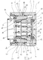
- the hydraulic radial press shown in the drawing comprises as main components an im Essentially rotationally symmetrical housing 1, an annular structure 2 guided therein along the axis X, and a pressing tool 4 having eight pressing jaws 3 arranged around the pressing axis X.
- the housing 1 comprises a one-piece housing basic structure 5 with a jacket section 6 and an annular support disk 7 on the end face , and a housing locking ring 8 arranged and fixed there in relation to the support disk 7 in the casing structure.
- the press jaws 3 are supported by guide grooves 10 provided on the support disk 7 by means of the (preferably two) screws 9 and being provided on the press jaws 3 interacting guide elements 11 (sliding blocks) guided radially displaceably - on the support disk 7, a friction-reducing bearing plate 12 being arranged between the end faces of the press jaws 3 and the support disk 7.
- the press jaws have 3 sliding surfaces 13 radially on the outside. These form counter surfaces to control surfaces 14 which are provided on the ring structure 2 and are inclined with respect to the pressing axis X and which cooperate with the sliding surfaces 13 in such a way that an axial displacement (arrow A) of the ring structure 2 in the direction of the support disk 7 results in a radially inward movement ( Arrow B) causes the press jaws 3.
- the ratio of the axial movement of the ring structure 2 to the radial movement of the pressing jaws 3 changes over the total possible movement path of the ring structure 2, in that the angle of inclination of the control surfaces 14 changes along their course in the axial direction
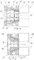
- the ring structure 2 has a ring-shaped closed base structure 15 and eight control bodies 16 which are interchangeably accommodated therein and on which the control surfaces 14 are designed.
- the control bodies are in turn multi-part in that they each have a (in the present case essentially flat) base plate 17 and a bump 18 placed thereon in sections, and two sliding plates 19 - on the base plate 17 or bump 18 - on which the control surfaces 14 are designed are.
- the (angled) sliding plates 19 are fastened to the base plate 17 or the hump 18 by means of laterally arranged, angled fixing lugs 20 and screws 21.
- the humps 18 are each fixed to the associated base plate 17 by means of centering pins 22 and screws 23.
- each of which is defined by two ribs 25 and a support surface 26 arranged between them.
- the base plates 17 of the control bodies 16 lie against the base structure 15 on flat support surfaces 26; they accordingly have flat back surfaces 27.
- the control bodies 16 are pushed axially into the assigned pockets 24, whereby pins 28 protruding laterally from the base plate 17 enter the associated recesses 29 provided in the ribs 25.
- a screw 30, which is screwed into the ribs 25 at the end, on the Base structure 15 of the securing ring 31 fixed to the ring structure 2, the eight control bodies 16 are then secured in their assembled position.
- control bodies 16 which are interchangeably accommodated in the base structure 15 which, through their specific geometry which determines the course of the control surfaces 14, have that individual-characteristic relationship between the axial movement of the ring structure 2 and the radial movement of the ring structure induced thereby Define press jaws 3 which is decisive for the operating characteristics of the respective radial press in its specific configuration with control bodies 16.
- Expedient modifications to the above-described embodiment can consist in that a segmented circlip 31 or individual circlips are used to fix the control bodies 16, the circlip segments or circlips in question again preferably using screws (for example, each arranged in the joint of two circlips) be fixed at the front on the ribs 25.
- the pins 28 on the control bodies 16 can be omitted, for example by fixing the control bodies 16 (for example by means of two screws) on the end face to the locking ring 31 or the locking ring segments or locking plates.
- the ring structure 15 - to simplify its manufacture - could, for example, have (flat or crowned) supporting surfaces extending parallel to the pressing axis X, in which case the Control body 16 would receive a basically wedge-shaped basic shape.
- the control surfaces 14 of each control body 16 have four flat areas, which are offset in pairs in parallel to one another, namely two rapid traverse areas 32 with a large angle of inclination with respect to the axis X and two power gear areas 33 with a small angle of inclination with respect to the axis X. In this way, the control surfaces 14 each lie on a polygon with planes perpendicular to the press axis X, each having corners arranged between two adjacent press jaws 3. Because each of the two sliding plates 19 of each control body 16 is simply angled, there is an edge-free transition (with a small radius) from the respective rapid traction area 32 of the control surface 14 to the associated power passage area 33. In a development which is preferred over the illustrated embodiment, the two sliding plates are 19 identical to each other.
- the sliding surfaces 13 of the pressing jaws 3 also have four flat regions, each offset in parallel to one another in pairs, namely two rapid traverse regions 34 with a large inclination angle with respect to the X axis and two power transmission regions 35 with a small inclination angle with respect to the X axis during the pressing process - apart from the transition from rapid to power - each of the eight pressing jaws 3 with their sliding surfaces 13 is always flat, in the area of two axially spaced surfaces, on the corresponding control surfaces 14 of the ring structure 2, the size of the contact surfaces during of Force increases steadily.
- the ribs 25 already mentioned above protrude radially inward beyond the control surfaces 14, so that - as press jaw guide ribs 36 - they also ensure the guidance of the press jaws 3 in the axial direction.
- a double-acting hydraulic drive is used to move the ring structure 2.
- the ring structure 2 comprises an annular piston 37, which is sealingly guided in a cylinder section 38 embodied in the jacket section 6 of the housing 1.
- the cylinder section 38, the annular piston 37, the housing locking ring 8 and a sleeve-shaped extension 39 of the ring structure 2, which is sealingly guided therein, jointly delimit an annular press working space 40. This can be acted upon via the press connection 41.
- An annular return stroke work space 42 is arranged between the press work space 40 and the support disk 7.
- the jacket section 6 of the housing 1 has a dirt outlet opening 47 between the support disk 7 and the sealing collar 44, namely directly adjacent to the latter, at the lowest point of the relevant annular space 46. According to the present embodiment, their diameter or opening width is preferred greater than the maximum distance between two adjacent pressing jaws 3 in the maximum open position of the tool. Through the dirt outlet opening 47, dirt that has entered the annular space 46 can thus reliably leave it again.
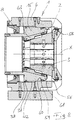
- the sliding surfaces 13 of the pressing jaws 3 are designed such that they each have exactly one flat region 50 and an area 51 which extends into these without edges and extends over a considerable part of the axial extent of the sliding surface 13, in which the angle of inclination of the sliding surface 13 changes continuously with respect to the X axis.
- This geometry is illustrated by means of a construction in which - in contrast to the present invention - the control surfaces 14 are implemented directly on the base structure 15 of the ring structure 2. The same can obviously be seen in that in the Figures 1 to 4 implement the principle that is characteristic of the present invention with separate, interchangeable control bodies. Likewise, this control surface geometry is not only realizable in such radial presses as the one after Fig. 5 , require lubrication, but also with lubrication-free, separate sliding plates with radial presses.
- a non-metallic fiber reinforcement ring 53 is incorporated into the ring structure 2, namely into a corresponding ring groove 52 of the base structure 15 at its end region facing the support disk 7. This extends closed in a plane perpendicular to the axis X around the axis X and is flush with the outside of the cylinder surface 45, so that the scraper 54 inserted in the sealing collar 44 has the same surface as the outer surface of the fiber reinforcement ring 53 and the cylindrical surface 45 of dirt cleans.
- Fig. 6 illustrates another modified (lubrication-free) radial press that differs from that to the Figures 1 to 4 essentially differs in that here sliding plates 55 are not assigned to the ring structure 2, but rather to the pressing jaws 3, so that the sliding surfaces 13 are designed on the sliding plates 55.
- Fig. 5 the above information applies Fig. 5 ; ie the illustrated principle of the sliding plates 55 on the press jaw side could also be seen in other geometries of the control surfaces 14 and Sliding surfaces 13 like those after Fig. 5 implement.
- the control surfaces 14, instead of being embodied directly on the base structure 15 of the ring structure 2 can be embodied on separate, exchangeable control bodies in a manner corresponding to the present invention.
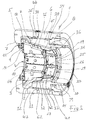
- FIG. 7 and 8th The illustrated embodiment of the invention is also largely explained by the above explanations of FIG Figures 1 to 6 which are referred to to avoid repetition.
- An essential distinctive feature of this embodiment from the previously described consists in the eight openings 56 provided on the housing 1 at the transition from the casing section 6 to the support disk 7 and arranged in alignment with the pressing jaws 3. These take over the function of the dirt outlet opening 47 according to those explained above Embodiments and are otherwise dimensioned such that the guide elements 11 can be inserted through the openings 56 into the housing 1.
- the guide elements 11 are angled and each have a fixing tab 58 which lies radially on the outside on a support surface 57.
- the guide elements 11 are screwed from the radially outside to the housing 1 in the area of the openings 56. In this way, threaded holes can be dispensed from the front side of the support disk 7, which accommodates the flow of force in this heavily loaded part.
- the return stroke working space 42 is also designed somewhat differently than in the previously described embodiments.
- the sealing does not take place in the area of a sealing collar fixed to the housing, but rather in the area of a seal 59 which is inserted into an annular groove 60 of the base structure 15 of the ring structure 2 and is sealingly guided in a cylinder section 61 embodied in the jacket section 6, which has a slightly smaller diameter than the cylinder section 38 delimiting the press working space.
- control body which can be exchangeably inserted into the base structure 15 of the ring structure 2 and which has the control surface 14 which is executed thereon (on a sliding plate 19).
- the control bodies here are only in two parts with a stepped sliding plate carrier 63, which functions as the base plate 17 and the hump 18 of the exemplary embodiment according to FIGS Figures 1 to 4 is united in itself and is geometrically designed accordingly.
- the interchangeable slide plates 19, which are continuous in one piece, are each screwed axially (on the end face) to the slide plate carrier 63 concerned.
- the explanations for the geometry of the control surfaces 14 and the sliding surfaces 13 apply Figures 1 to 4 in a corresponding manner.
- the pressing jaws 3 - in the usual way - are designed to interchangeably hold the pressing jaw heads are.
- they have receiving bores 64 for holding pins arranged on the press jaw heads and associated locks 65.
- Illustrated implementation of the present invention on a radial press constructed in the form of a pressure plate has an end-side support plate 7 'of approximately square format extending around an opening 66 and an annular structure 2' which is displaceable relative to the support plate 7 'along the press axis X.
- the function of the support plate 7 ' corresponds to the extent relevant here to the function of the support plate 7 according to the exemplary embodiments according to FIGS Figures 1 to 8 .
- the eight press jaws 3 ' are supported on it in a radially displaceable manner.
- the function of the ring structure 2 ' corresponds to the extent relevant here to the function of the ring structure 2 according to the exemplary embodiments according to FIGS Figures 1 to 8 .
- the ring structure 2 ' comprises a base structure 15' and eight interchangeable control bodies 16 'with control surfaces 14' which are accommodated therein, each between two guide ribs (not shown) for the press rivets 3 '.
- the control bodies 16 ' are fixed to the base structure 15' by means of the securing ring 31.
- the structure of the control body (cf. Fig. 12 ) is based on the one in Fig. 4 shown control body 16, so that reference is made to the corresponding explanations.
- control body 16 'in the rest of the ring structure 2' The same applies to the integration of the control body 16 'in the rest of the ring structure 2'.
- the control surfaces 14 'in each case on a polygon, each with corners arranged between two adjacent pressing jaws 3'.
- a drive unit 67 which causes their relative movement to one another and comprises a plurality (for example four) of cylinder-piston structures.
- the cylinders 70 of the cylinder-piston structures are firmly connected to the base structure 15 'of the ring structure 2'.
- Piston rods 68 connected to the pistons are designed as pull rods 69 and are connected at the end to the support plate 7 '.
Landscapes
- Engineering & Computer Science (AREA)
- Mechanical Engineering (AREA)
- Automatic Assembly (AREA)
- Presses And Accessory Devices Thereof (AREA)
Claims (29)
- Presse radiale pourvue d'un carter (1) comportant une partie d'enveloppe (6) et une plaque d'appui (7) frontale, de forme annulaire, une structure annulaire (2) guidée en étant déplaçable en son intérieur le long d'un axe de la presse (X) et plusieurs mâchoires de pressage (3), placées autour de l'axe de la presse (X), qui s'appuient sur la plaque d'appui (7) en étant guidées en déplacement radial et sur lesquelles la structure annulaire (2) agit au moyen de surfaces de commande (14) inclinées par rapport à l'axe de la presse (X), lesquelles sont adjacentes à des surfaces antagonistes réalisées sous la forme de surfaces de glissement (13) des mâchoires de pressage (3), l'angle d'inclinaison des surfaces de commande (14) variant le long de son trajet dans la direction axiale, de telle sorte que sur le trajet de déplacement maximum de la structure annulaire (2), son déplacement axial et le déplacement radial des mâchoires de pressage (3) provoqué par celui-ci présentent différents rapports mutuels, caractérisée en ce que la structure annulaire (2) comporte une structure de base (15) et des organes de commande (16) interchangeables, réceptionnés dans cette dernière, dont la géométrie tridimensionnelle définit la caractéristique de la relation entre le déplacement axial de la structure annulaire (2) et le déplacement radial des mâchoires de pressage (3), pourvus de surfaces de commande (14) réalisés sur ceux-ci, dans des plans perpendiculaires à l'axe de la presse (X), les surfaces de commande (14) reposant chacune sur un polygone avec des angles placés respectivement entre deux mâchoires de pressage (3) voisines.
- Presse radiale selon la revendication 1, caractérisée en ce que les organes de commande (16) sont adjacents chacun le long d'une surface d'appui (26) plane, sur la structure de base (15).
- Presse radiale selon la revendication 1, caractérisée en ce que les organes de commande (16) sont adjacents chacun à pleine surface à une surface d'appui (26) bombée de la structure de base (15).
- Presse radiale selon la revendication 2 ou la revendication 3, caractérisée en ce que les surfaces d'appui (26) sont convergentes en direction axiale.
- Presse radiale selon la revendication 2 ou la revendication 3, caractérisée en ce que les surfaces d'appui (26) s'étendent à la parallèle de l'axe de la presse (X).
- Presse radiale selon l'une quelconque des revendications 1 à 5, caractérisée en ce qu'entre deux organes de commande (16) sont prévues des rainures de guidage des mâchoires de pressage (36) réalisées chaque fois sur la structure de base (15).
- Presse radiale selon l'une quelconque des revendications 1 à 5, caractérisée en ce que les organes de commande (16) comportent des rainures de guidage latérales des mâchoires de pressage (36).
- Presse radiale selon l'une quelconque des revendications 1 à 7, caractérisée en ce que les organes de commande (16) comportent chacun une plaque d'embase (17) adjacente à la structure de base (15) et un bossage (18) posé en partie sur celle-ci.
- Presse radiale selon l'une quelconque des revendications 1 à 8, caractérisée en ce que l'angle d'inclinaison des surfaces de commande (14) change en continu sur une majeure partie de leur extension.
- Presse radiale selon l'une quelconque des revendications 1 à 8, caractérisée en ce que les surfaces de commande (14) comportent au moins deux zones planes (32 ; 33) discrètes.
- Presse radiale selon la revendication 10, caractérisée en ce que les surfaces de commande (14) comportent quatre zones planes (32, 33) décalées par paires l'une par rapport à l'autre.
- Presse radiale selon la revendication 10 ou la revendication 11, caractérisée en ce que des zones planes (32, 33) voisines passent l'une dans l'autre sans arête.
- Presse radiale selon l'une quelconque des revendications 1 à 12, caractérisée en ce qu'au moins dans des positions de service individuelles de ls structure annulaire (2), ses surfaces de commande (14) et les surfaces de glissement (13) des mâchoires de pressage (3) sont adjacentes à pleine surface.
- Presse radiale selon l'une quelconque des revendications 1 à 13, caractérisée en ce que les surfaces de commande (14) sont réalisées sur la surface de tôles de coulissement (19) interchangeables.
- Presse radiale selon l'une quelconque des revendications 1 à 13, caractérisée en ce que les mâchoires de pressage (3) comportent des tôles de coulissement (55) interchangeables, sur lesquelles sont réalisées les surfaces de glissement (13).
- Presse radiale selon l'une quelconque des revendications 1 à 15, caractérisée en ce que la structure annulaire (2) comporte un piston annulaire (37) qui est guidé de manière à assurer l'étanchéité dans une partie d'un cylindre de pressage (38) réalisée dans la partie d'enveloppe (6) du carter (1) et qui conjointement avec celle-ci, délimite un espace fonctionnel de presse (40) de forme annulaire.
- Presse radiale selon la revendication 16, caractérisée en ce qu'entre l'espace fonctionnel de presse (40) et la plaque d'appui (7) est placé un espace fonctionnel de course de retour (42), qui est délimité par une surface cylindrique (45) placée sur la périphérie extérieure de la structure annulaire (2), guidée dans une collerette d'étanchéité (44) stationnaire sur le carter.
- Presse radiale selon la revendication 17, caractérisée en ce que l'espace fonctionnel de course de retour (42) est délimité par la partie de cylindre de pressage (38) et par une zone annulaire (43) réalisée sur le piston annulaire (37), sur la face frontale de celui-ci qui est opposée à l'espace fonctionnel de presse (40).
- Presse radiale selon la revendication 17 ou la revendication 18, caractérisée en ce que la partie d'enveloppe (6) du carter (1) comporte entre la collerette d'étanchéité (44) et la plaque d'appui (7) un orifice d'évacuation des impuretés (47).
- Presse radiale selon l'une quelconque des revendications 16 à 19, caractérisée en ce que l'espace fonctionnel de presse (40) est délimité par une bague de verrouillage de carter (8), placée en regard de la plaque d'appui (7) et un prolongement (39) en forme de douille de la structure annulaire (2), placé de manière à assurer l'étanchéité dans celle-ci.
- Presse radiale selon l'une quelconque des revendications 1 à 20, caractérisée en ce que la plaque d'appui (7) et la partie d'enveloppe (6) sont un élément d'une structure de base (5) en monobloc du carter.
- Presse radiale selon l'une quelconque des revendications 1 à 21, caractérisée en ce que sur sa zone d'extrémité qui fait face à la plaque d'appui (7), la structure annulaire (2) est entourée d'une bague de renfort (53) non métallique à fibres.
- Presse radiale selon l'une quelconque des revendications 1 à 22, caractérisée en ce sur la plaque d'appui (7) sont montés des éléments de guidage (11) interchangeables, coopérant avec les mâchoires de pressage (3).
- Presse radiale selon l'une quelconque des revendications 1 à 23, caractérisée en ce que sur le passage de la partie d'enveloppe (6) vers la plaque d'appui (7), le carter (1) comporte un nombre d'ajours (56) correspondant au nombre des mâchoires de pressage (3) .
- Presse radiale selon la revendication 23 et la revendication 24, caractérisée en ce que les éléments de guidage (11) sont insérables dans le carter (1) à travers les ajours (56).
- Presse radiale selon la revendication 25, caractérisée en ce que les éléments de guidage (11) sont coudés et comportent chacun une patte de fixation (58) adjacente à l'extérieur en direction radiale à une surface d'appui (57).
- Presse radiale selon la revendication 26, caractérisée en ce que dans la zone des ajours (56), les éléments de guidage (11) sont vissés par l'extérieur en direction radiale avec le carter (1).
- Presse radiale, pourvue d'une plaque d'appui (7') frontale, s'étendant sous forme annulaire autour d'un ajour (66), d'une structure annulaire (2') guidée en étant déplaçable par rapport à cette dernière le long d'un axe de la presse (X), d'une unité d'entraînement (67) agissant entre la plaque d'appui (7') et la structure annulaire (2') et de plusieurs mâchoires de pressage (3') placées autour de l'axe de la presse (X), qui avec une composante directionnelle radiale, s'appuient sur la plaque d'appui (7') en étant guidées de manière déplaçable et sur lesquelles la structure annulaire (2') agit au moyen de surfaces de commande (14') inclinées par rapport à l'axe de la presse (X), lesquelles sont adjacentes à des surfaces antagonistes des mâchoires de pressage (3') réalisées sous la forme de surfaces de glissement (13'), l'angle d'inclinaison des surfaces de commande (14') variant le long de son trajet dans la direction axiale, de telle sorte que sur le trajet de déplacement maximum de la structure annulaire (2') et de la plaque d'appui, l'une vers l'autre, le déplacement axial concerné et le déplacement radial des mâchoires de pressage (3') provoqué par celui-ci présentent différents rapports mutuels,
caractérisée en ce que
la structure annulaire (2') comporte une structure de base (15') et des organes de commande (16') interchangeables, réceptionnés dans cette dernière, dont la géométrie tridimensionnelle définit la caractéristique de la relation entre le déplacement axial de la structure annulaire (2') et le déplacement radial des mâchoires de pressage (3'), pourvus de surfaces de commande (14') réalisées sur ceux-ci, dans des plans perpendiculaires à l'axe de la presse (X), les surfaces de commande (14') reposant chacune sur un polygone avec des angles placés respectivement entre deux mâchoires de pressage (3') voisines. - Presse radiale selon la revendication 28, caractérisée en ce que les mâchoires de pressage (3') s'appuient sur la plaque d'appui (7') en étant guidées de manière déplaçable en direction radiale.
Applications Claiming Priority (2)
| Application Number | Priority Date | Filing Date | Title |
|---|---|---|---|
| DE102016106650.8A DE102016106650B4 (de) | 2016-04-12 | 2016-04-12 | Radialpresse |
| PCT/EP2017/058731 WO2017178508A1 (fr) | 2016-04-12 | 2017-04-12 | Presse radiale |
Publications (2)
| Publication Number | Publication Date |
|---|---|
| EP3442784A1 EP3442784A1 (fr) | 2019-02-20 |
| EP3442784B1 true EP3442784B1 (fr) | 2020-03-11 |
Family
ID=58544950
Family Applications (1)
| Application Number | Title | Priority Date | Filing Date |
|---|---|---|---|
| EP17717154.3A Active EP3442784B1 (fr) | 2016-04-12 | 2017-04-12 | Presse radiale |
Country Status (4)
| Country | Link |
|---|---|
| US (1) | US11052447B2 (fr) |
| EP (1) | EP3442784B1 (fr) |
| DE (1) | DE102016106650B4 (fr) |
| WO (1) | WO2017178508A1 (fr) |
Families Citing this family (13)
| Publication number | Priority date | Publication date | Assignee | Title |
|---|---|---|---|---|
| DE102018115744A1 (de) | 2018-06-29 | 2020-01-02 | Uniflex-Hydraulik Gmbh | Radialpresse sowie Verfahren zum Fügen zweier Bauteile mittels Radialpressung |
| DE102018115750B3 (de) | 2018-06-29 | 2019-07-11 | Uniflex-Hydraulik Gmbh | Radialpresse sowie Verfahren zum Fügen zweier Bauteile mittels Radialpressung |
| CN113632015B (zh) | 2019-03-29 | 2024-05-28 | 尤尼弗莱克斯-液压有限责任公司 | 用于制造多个复合结构的方法 |
| DE102020121143B4 (de) * | 2020-08-11 | 2022-03-10 | Uniflex - Hydraulik GmbH | Radialpresse |
| DE102020121142B4 (de) * | 2020-08-11 | 2022-03-10 | Uniflex - Hydraulik GmbH | Radialpresse |
| DE102020125890B3 (de) | 2020-10-02 | 2022-03-10 | Uniflex - Hydraulik GmbH | Radialpresse |
| DE102021109039B4 (de) | 2021-04-12 | 2023-02-23 | Uniflex - Hydraulik GmbH | Radialpresse |
| EP4144456B1 (fr) | 2021-09-02 | 2025-11-26 | Uniflex-Hydraulik GmbH | Procédé de fabrication d'une conduite hydraulique à haute pression |
| DE102022109427B4 (de) | 2022-04-19 | 2024-04-25 | Uniflex - Hydraulik GmbH | Radialpresse |
| DE202022102074U1 (de) | 2022-04-19 | 2022-04-27 | Uniflex - Hydraulik GmbH | Radialpresse |
| DE102023109974B3 (de) | 2023-04-20 | 2024-06-20 | Uniflex - Hydraulik GmbH | Radialpresse |
| CN116748394B (zh) * | 2023-06-30 | 2024-01-16 | 温州伟力汽车部件有限公司 | 一种传感器铜套锁口工装 |
| DE102024125020B3 (de) | 2024-09-02 | 2025-10-30 | Uniflex - Hydraulik GmbH | Radialpresse |
Family Cites Families (13)
| Publication number | Priority date | Publication date | Assignee | Title |
|---|---|---|---|---|
| US2427685A (en) * | 1944-01-15 | 1947-09-23 | Carl R Midtlyng | Method of securing inner and outer sleeves to hose ends |
| US2999405A (en) * | 1957-12-24 | 1961-09-12 | Smith Corp A O | Apparatus for radially compressing articles |
| GB1569126A (en) * | 1976-02-24 | 1980-06-11 | Andrew Hydraulics Int | Device for crimping tubular elements |
| DE2844475C2 (de) * | 1978-10-12 | 1983-09-29 | Peter Ing.(grad.) 6380 Bad Homburg Schröck | Radialpresse für Werkstücke mit zylindrischer Außenfläche |
| DE3611253A1 (de) * | 1986-04-04 | 1987-10-08 | Peter Dipl Ing Schroeck | Radialpresse |
| DE4135465A1 (de) * | 1991-10-28 | 1993-04-29 | Schroeck Peter Dipl Ing Fh | Radialpresse mit zwei radial gegeneinander beweglichen pressenjochen |
| AUPQ886200A0 (en) * | 2000-07-19 | 2000-08-10 | Betaswage Pty Ltd | Hydraulic swage press |
| DE10149924A1 (de) | 2001-10-10 | 2003-04-30 | Uniflex Hydraulik Gmbh | Radialpresse |
| WO2005077566A1 (fr) | 2004-02-16 | 2005-08-25 | Betaswage Pty Ltd | Perfectionnements apportés à des matrices d'emboutissage |
| US8230714B2 (en) * | 2009-01-23 | 2012-07-31 | Custom Machining Services, Inc. | Die carrier assembly and crimping process |
| US20110185785A1 (en) | 2010-02-04 | 2011-08-04 | Eagle Press & Equipment Co. Ltd. | Servo Hemming Press |
| AU2011200404B2 (en) | 2010-02-02 | 2016-01-21 | Betaswage Pty Ltd | Hydraulic Swage Press |
| DE102011015706A1 (de) * | 2011-03-31 | 2012-10-04 | Uniflex-Hydraulik Gmbh | Radialpresse |
-
2016
- 2016-04-12 DE DE102016106650.8A patent/DE102016106650B4/de active Active
-
2017
- 2017-04-12 WO PCT/EP2017/058731 patent/WO2017178508A1/fr not_active Ceased
- 2017-04-12 EP EP17717154.3A patent/EP3442784B1/fr active Active
-
2018
- 2018-10-09 US US16/154,990 patent/US11052447B2/en active Active
Non-Patent Citations (1)
| Title |
|---|
| None * |
Also Published As
| Publication number | Publication date |
|---|---|
| WO2017178508A1 (fr) | 2017-10-19 |
| US20190039113A1 (en) | 2019-02-07 |
| EP3442784A1 (fr) | 2019-02-20 |
| DE102016106650A1 (de) | 2017-10-12 |
| US11052447B2 (en) | 2021-07-06 |
| DE102016106650B4 (de) | 2021-09-16 |
Similar Documents
| Publication | Publication Date | Title |
|---|---|---|
| EP3442784B1 (fr) | Presse radiale | |
| EP3189237B1 (fr) | Pompe excentrique à vis | |
| DE3149067C2 (fr) | ||
| AT511833B1 (de) | Mastaufbau insbesondere für eine autobetonpumpe | |
| EP3414086B1 (fr) | Presse radiale | |
| EP0228030B1 (fr) | Machine de forgeage | |
| DE4130811C2 (de) | Presse mit verstellbarem Hub | |
| EP3409391B1 (fr) | Unité d'outil pour une machine d'extrusion destiné à la fabrication en continu d'un profilé d'une matière à extruder déformable | |
| DE10114117B4 (de) | Zylinder mit Führung | |
| EP1995471B1 (fr) | Cylindre verrouillable à palier fluidique | |
| DE2415549B2 (de) | Vorrichtung für die spanlose Kaltverformung eines Rohlings | |
| DE29713944U1 (de) | Druckmittelbetätigbare Kniehebelspannvorrichtung | |
| DE4209999C2 (de) | Spannfutter für Werkzeugmaschinen | |
| EP1044759A2 (fr) | Outil de maniement pour une machine-outil | |
| EP2691192B1 (fr) | Presse radiale | |
| EP3113892B1 (fr) | Coulisseau porte-outil | |
| EP3491254B1 (fr) | Unité piston d'un vérin hydraulique | |
| EP0809736A1 (fr) | Mecanisme vireur pour benne preneuse | |
| EP4093601B1 (fr) | Presse radiale | |
| DE29824688U1 (de) | Radialpresse | |
| EP2039944A2 (fr) | Actionneur linéaire, en particulier unité cylindre-piston dotée d'un dispositif de verrouillage | |
| DE69002993T2 (de) | Haupthebel für schnell laufende Drehschaftmaschinen. | |
| DE102024125020B3 (de) | Radialpresse | |
| EP0305549B1 (fr) | Chambre de decalaminage de feuillards avec des poudres abrasives | |
| DE102010048030B4 (de) | Antriebsvorrichtung |
Legal Events
| Date | Code | Title | Description |
|---|---|---|---|
| STAA | Information on the status of an ep patent application or granted ep patent |
Free format text: STATUS: UNKNOWN |
|
| STAA | Information on the status of an ep patent application or granted ep patent |
Free format text: STATUS: THE INTERNATIONAL PUBLICATION HAS BEEN MADE |
|
| PUAI | Public reference made under article 153(3) epc to a published international application that has entered the european phase |
Free format text: ORIGINAL CODE: 0009012 |
|
| STAA | Information on the status of an ep patent application or granted ep patent |
Free format text: STATUS: REQUEST FOR EXAMINATION WAS MADE |
|
| 17P | Request for examination filed |
Effective date: 20181011 |
|
| AK | Designated contracting states |
Kind code of ref document: A1 Designated state(s): AL AT BE BG CH CY CZ DE DK EE ES FI FR GB GR HR HU IE IS IT LI LT LU LV MC MK MT NL NO PL PT RO RS SE SI SK SM TR |
|
| AX | Request for extension of the european patent |
Extension state: BA ME |
|
| DAV | Request for validation of the european patent (deleted) | ||
| DAX | Request for extension of the european patent (deleted) | ||
| GRAP | Despatch of communication of intention to grant a patent |
Free format text: ORIGINAL CODE: EPIDOSNIGR1 |
|
| STAA | Information on the status of an ep patent application or granted ep patent |
Free format text: STATUS: GRANT OF PATENT IS INTENDED |
|
| INTG | Intention to grant announced |
Effective date: 20191007 |
|
| GRAS | Grant fee paid |
Free format text: ORIGINAL CODE: EPIDOSNIGR3 |
|
| GRAA | (expected) grant |
Free format text: ORIGINAL CODE: 0009210 |
|
| STAA | Information on the status of an ep patent application or granted ep patent |
Free format text: STATUS: THE PATENT HAS BEEN GRANTED |
|
| AK | Designated contracting states |
Kind code of ref document: B1 Designated state(s): AL AT BE BG CH CY CZ DE DK EE ES FI FR GB GR HR HU IE IS IT LI LT LU LV MC MK MT NL NO PL PT RO RS SE SI SK SM TR |
|
| REG | Reference to a national code |
Ref country code: GB Ref legal event code: FG4D Free format text: NOT ENGLISH |
|
| REG | Reference to a national code |
Ref country code: CH Ref legal event code: EP |
|
| REG | Reference to a national code |
Ref country code: AT Ref legal event code: REF Ref document number: 1242619 Country of ref document: AT Kind code of ref document: T Effective date: 20200315 |
|
| REG | Reference to a national code |
Ref country code: IE Ref legal event code: FG4D Free format text: LANGUAGE OF EP DOCUMENT: GERMAN |
|
| REG | Reference to a national code |
Ref country code: DE Ref legal event code: R096 Ref document number: 502017004202 Country of ref document: DE |
|
| REG | Reference to a national code |
Ref country code: FI Ref legal event code: FGE |
|
| PG25 | Lapsed in a contracting state [announced via postgrant information from national office to epo] |
Ref country code: NO Free format text: LAPSE BECAUSE OF FAILURE TO SUBMIT A TRANSLATION OF THE DESCRIPTION OR TO PAY THE FEE WITHIN THE PRESCRIBED TIME-LIMIT Effective date: 20200611 Ref country code: RS Free format text: LAPSE BECAUSE OF FAILURE TO SUBMIT A TRANSLATION OF THE DESCRIPTION OR TO PAY THE FEE WITHIN THE PRESCRIBED TIME-LIMIT Effective date: 20200311 |
|
| REG | Reference to a national code |
Ref country code: NL Ref legal event code: MP Effective date: 20200311 |
|
| PG25 | Lapsed in a contracting state [announced via postgrant information from national office to epo] |
Ref country code: GR Free format text: LAPSE BECAUSE OF FAILURE TO SUBMIT A TRANSLATION OF THE DESCRIPTION OR TO PAY THE FEE WITHIN THE PRESCRIBED TIME-LIMIT Effective date: 20200612 Ref country code: BG Free format text: LAPSE BECAUSE OF FAILURE TO SUBMIT A TRANSLATION OF THE DESCRIPTION OR TO PAY THE FEE WITHIN THE PRESCRIBED TIME-LIMIT Effective date: 20200611 Ref country code: HR Free format text: LAPSE BECAUSE OF FAILURE TO SUBMIT A TRANSLATION OF THE DESCRIPTION OR TO PAY THE FEE WITHIN THE PRESCRIBED TIME-LIMIT Effective date: 20200311 Ref country code: LV Free format text: LAPSE BECAUSE OF FAILURE TO SUBMIT A TRANSLATION OF THE DESCRIPTION OR TO PAY THE FEE WITHIN THE PRESCRIBED TIME-LIMIT Effective date: 20200311 Ref country code: SE Free format text: LAPSE BECAUSE OF FAILURE TO SUBMIT A TRANSLATION OF THE DESCRIPTION OR TO PAY THE FEE WITHIN THE PRESCRIBED TIME-LIMIT Effective date: 20200311 |
|
| REG | Reference to a national code |
Ref country code: LT Ref legal event code: MG4D |
|
| PG25 | Lapsed in a contracting state [announced via postgrant information from national office to epo] |
Ref country code: NL Free format text: LAPSE BECAUSE OF FAILURE TO SUBMIT A TRANSLATION OF THE DESCRIPTION OR TO PAY THE FEE WITHIN THE PRESCRIBED TIME-LIMIT Effective date: 20200311 |
|
| PG25 | Lapsed in a contracting state [announced via postgrant information from national office to epo] |
Ref country code: PT Free format text: LAPSE BECAUSE OF FAILURE TO SUBMIT A TRANSLATION OF THE DESCRIPTION OR TO PAY THE FEE WITHIN THE PRESCRIBED TIME-LIMIT Effective date: 20200805 Ref country code: CZ Free format text: LAPSE BECAUSE OF FAILURE TO SUBMIT A TRANSLATION OF THE DESCRIPTION OR TO PAY THE FEE WITHIN THE PRESCRIBED TIME-LIMIT Effective date: 20200311 Ref country code: LT Free format text: LAPSE BECAUSE OF FAILURE TO SUBMIT A TRANSLATION OF THE DESCRIPTION OR TO PAY THE FEE WITHIN THE PRESCRIBED TIME-LIMIT Effective date: 20200311 Ref country code: SM Free format text: LAPSE BECAUSE OF FAILURE TO SUBMIT A TRANSLATION OF THE DESCRIPTION OR TO PAY THE FEE WITHIN THE PRESCRIBED TIME-LIMIT Effective date: 20200311 Ref country code: EE Free format text: LAPSE BECAUSE OF FAILURE TO SUBMIT A TRANSLATION OF THE DESCRIPTION OR TO PAY THE FEE WITHIN THE PRESCRIBED TIME-LIMIT Effective date: 20200311 Ref country code: SK Free format text: LAPSE BECAUSE OF FAILURE TO SUBMIT A TRANSLATION OF THE DESCRIPTION OR TO PAY THE FEE WITHIN THE PRESCRIBED TIME-LIMIT Effective date: 20200311 Ref country code: RO Free format text: LAPSE BECAUSE OF FAILURE TO SUBMIT A TRANSLATION OF THE DESCRIPTION OR TO PAY THE FEE WITHIN THE PRESCRIBED TIME-LIMIT Effective date: 20200311 Ref country code: IS Free format text: LAPSE BECAUSE OF FAILURE TO SUBMIT A TRANSLATION OF THE DESCRIPTION OR TO PAY THE FEE WITHIN THE PRESCRIBED TIME-LIMIT Effective date: 20200711 |
|
| REG | Reference to a national code |
Ref country code: CH Ref legal event code: PL |
|
| REG | Reference to a national code |
Ref country code: DE Ref legal event code: R097 Ref document number: 502017004202 Country of ref document: DE |
|
| PG25 | Lapsed in a contracting state [announced via postgrant information from national office to epo] |
Ref country code: MC Free format text: LAPSE BECAUSE OF FAILURE TO SUBMIT A TRANSLATION OF THE DESCRIPTION OR TO PAY THE FEE WITHIN THE PRESCRIBED TIME-LIMIT Effective date: 20200311 |
|
| PLBE | No opposition filed within time limit |
Free format text: ORIGINAL CODE: 0009261 |
|
| STAA | Information on the status of an ep patent application or granted ep patent |
Free format text: STATUS: NO OPPOSITION FILED WITHIN TIME LIMIT |
|
| PG25 | Lapsed in a contracting state [announced via postgrant information from national office to epo] |
Ref country code: LU Free format text: LAPSE BECAUSE OF NON-PAYMENT OF DUE FEES Effective date: 20200412 Ref country code: ES Free format text: LAPSE BECAUSE OF FAILURE TO SUBMIT A TRANSLATION OF THE DESCRIPTION OR TO PAY THE FEE WITHIN THE PRESCRIBED TIME-LIMIT Effective date: 20200311 Ref country code: LI Free format text: LAPSE BECAUSE OF NON-PAYMENT OF DUE FEES Effective date: 20200430 Ref country code: CH Free format text: LAPSE BECAUSE OF NON-PAYMENT OF DUE FEES Effective date: 20200430 Ref country code: DK Free format text: LAPSE BECAUSE OF FAILURE TO SUBMIT A TRANSLATION OF THE DESCRIPTION OR TO PAY THE FEE WITHIN THE PRESCRIBED TIME-LIMIT Effective date: 20200311 |
|
| REG | Reference to a national code |
Ref country code: BE Ref legal event code: MM Effective date: 20200430 |
|
| 26N | No opposition filed |
Effective date: 20201214 |
|
| PG25 | Lapsed in a contracting state [announced via postgrant information from national office to epo] |
Ref country code: PL Free format text: LAPSE BECAUSE OF FAILURE TO SUBMIT A TRANSLATION OF THE DESCRIPTION OR TO PAY THE FEE WITHIN THE PRESCRIBED TIME-LIMIT Effective date: 20200311 Ref country code: BE Free format text: LAPSE BECAUSE OF NON-PAYMENT OF DUE FEES Effective date: 20200430 Ref country code: SI Free format text: LAPSE BECAUSE OF FAILURE TO SUBMIT A TRANSLATION OF THE DESCRIPTION OR TO PAY THE FEE WITHIN THE PRESCRIBED TIME-LIMIT Effective date: 20200311 |
|
| PG25 | Lapsed in a contracting state [announced via postgrant information from national office to epo] |
Ref country code: IE Free format text: LAPSE BECAUSE OF NON-PAYMENT OF DUE FEES Effective date: 20200412 |
|
| GBPC | Gb: european patent ceased through non-payment of renewal fee |
Effective date: 20210412 |
|
| PG25 | Lapsed in a contracting state [announced via postgrant information from national office to epo] |
Ref country code: GB Free format text: LAPSE BECAUSE OF NON-PAYMENT OF DUE FEES Effective date: 20210412 |
|
| PG25 | Lapsed in a contracting state [announced via postgrant information from national office to epo] |
Ref country code: TR Free format text: LAPSE BECAUSE OF FAILURE TO SUBMIT A TRANSLATION OF THE DESCRIPTION OR TO PAY THE FEE WITHIN THE PRESCRIBED TIME-LIMIT Effective date: 20200311 Ref country code: MT Free format text: LAPSE BECAUSE OF FAILURE TO SUBMIT A TRANSLATION OF THE DESCRIPTION OR TO PAY THE FEE WITHIN THE PRESCRIBED TIME-LIMIT Effective date: 20200311 Ref country code: CY Free format text: LAPSE BECAUSE OF FAILURE TO SUBMIT A TRANSLATION OF THE DESCRIPTION OR TO PAY THE FEE WITHIN THE PRESCRIBED TIME-LIMIT Effective date: 20200311 |
|
| PG25 | Lapsed in a contracting state [announced via postgrant information from national office to epo] |
Ref country code: MK Free format text: LAPSE BECAUSE OF FAILURE TO SUBMIT A TRANSLATION OF THE DESCRIPTION OR TO PAY THE FEE WITHIN THE PRESCRIBED TIME-LIMIT Effective date: 20200311 Ref country code: AL Free format text: LAPSE BECAUSE OF FAILURE TO SUBMIT A TRANSLATION OF THE DESCRIPTION OR TO PAY THE FEE WITHIN THE PRESCRIBED TIME-LIMIT Effective date: 20200311 |
|
| REG | Reference to a national code |
Ref country code: AT Ref legal event code: MM01 Ref document number: 1242619 Country of ref document: AT Kind code of ref document: T Effective date: 20220412 |
|
| P01 | Opt-out of the competence of the unified patent court (upc) registered |
Effective date: 20230529 |
|
| PG25 | Lapsed in a contracting state [announced via postgrant information from national office to epo] |
Ref country code: AT Free format text: LAPSE BECAUSE OF NON-PAYMENT OF DUE FEES Effective date: 20220412 |
|
| PGFP | Annual fee paid to national office [announced via postgrant information from national office to epo] |
Ref country code: FI Payment date: 20250417 Year of fee payment: 9 |
|
| PGFP | Annual fee paid to national office [announced via postgrant information from national office to epo] |
Ref country code: DE Payment date: 20250626 Year of fee payment: 9 |
|
| PGFP | Annual fee paid to national office [announced via postgrant information from national office to epo] |
Ref country code: IT Payment date: 20250430 Year of fee payment: 9 |
|
| PGFP | Annual fee paid to national office [announced via postgrant information from national office to epo] |
Ref country code: FR Payment date: 20250422 Year of fee payment: 9 |