EP3442892B1 - Appareil destiné à être utilisé dans un système de dynamitage - Google Patents
Appareil destiné à être utilisé dans un système de dynamitage Download PDFInfo
- Publication number
- EP3442892B1 EP3442892B1 EP17728035.1A EP17728035A EP3442892B1 EP 3442892 B1 EP3442892 B1 EP 3442892B1 EP 17728035 A EP17728035 A EP 17728035A EP 3442892 B1 EP3442892 B1 EP 3442892B1
- Authority
- EP
- European Patent Office
- Prior art keywords
- conductor
- signal
- spool
- hub
- connector
- Prior art date
- Legal status (The legal status is an assumption and is not a legal conclusion. Google has not performed a legal analysis and makes no representation as to the accuracy of the status listed.)
- Active
Links
Images


Classifications
-
- B—PERFORMING OPERATIONS; TRANSPORTING
- B65—CONVEYING; PACKING; STORING; HANDLING THIN OR FILAMENTARY MATERIAL
- B65H—HANDLING THIN OR FILAMENTARY MATERIAL, e.g. SHEETS, WEBS, CABLES
- B65H75/00—Storing webs, tapes, or filamentary material, e.g. on reels
- B65H75/02—Cores, formers, supports, or holders for coiled, wound, or folded material, e.g. reels, spindles, bobbins, cop tubes, cans, mandrels or chucks
- B65H75/34—Cores, formers, supports, or holders for coiled, wound, or folded material, e.g. reels, spindles, bobbins, cop tubes, cans, mandrels or chucks specially adapted or mounted for storing and repeatedly paying-out and re-storing lengths of material provided for particular purposes, e.g. anchored hoses, power cables
- B65H75/38—Cores, formers, supports, or holders for coiled, wound, or folded material, e.g. reels, spindles, bobbins, cop tubes, cans, mandrels or chucks specially adapted or mounted for storing and repeatedly paying-out and re-storing lengths of material provided for particular purposes, e.g. anchored hoses, power cables involving the use of a core or former internal to, and supporting, a stored package of material
- B65H75/44—Constructional details
- B65H75/4481—Arrangements or adaptations for driving the reel or the material
- B65H75/4484—Electronic arrangements or adaptations for controlling the winding or unwinding process, e.g. with sensors
-
- B—PERFORMING OPERATIONS; TRANSPORTING
- B65—CONVEYING; PACKING; STORING; HANDLING THIN OR FILAMENTARY MATERIAL
- B65H—HANDLING THIN OR FILAMENTARY MATERIAL, e.g. SHEETS, WEBS, CABLES
- B65H49/00—Unwinding or paying-out filamentary material; Supporting, storing or transporting packages from which filamentary material is to be withdrawn or paid-out
- B65H49/18—Methods or apparatus in which packages rotate
- B65H49/20—Package-supporting devices
- B65H49/32—Stands or frameworks
-
- F—MECHANICAL ENGINEERING; LIGHTING; HEATING; WEAPONS; BLASTING
- F42—AMMUNITION; BLASTING
- F42D—BLASTING
- F42D1/00—Blasting methods or apparatus, e.g. loading or tamping
- F42D1/04—Arrangements for ignition
- F42D1/043—Connectors for detonating cords and ignition tubes, e.g. Nonel tubes
-
- F—MECHANICAL ENGINEERING; LIGHTING; HEATING; WEAPONS; BLASTING
- F42—AMMUNITION; BLASTING
- F42D—BLASTING
- F42D1/00—Blasting methods or apparatus, e.g. loading or tamping
- F42D1/08—Tamping methods; Methods for loading boreholes with explosives; Apparatus therefor
- F42D1/22—Methods for holding or positioning for blasting cartridges or tamping cartridges
Definitions
- This invention relates to an apparatus for use in a blasting system and, more particularly, is concerned with an apparatus which includes an elongate flexible signal-transmitting conductor which, in use, is connected to a detonator.
- a flexible signal-transmitting conductor such as a conductive wire, a fibre-optic cable, or a shock tube, is often provided, for use in a blasting system, in a compact form.
- the conductor is coiled and is then shrink-wrapped.
- One end of the conductor is fixed to a detonator while an opposing end is connected to an appropriately designed connector.
- the connector is one of a plurality of similar connectors which are electrically or otherwise coupled to a harness or distribution system.
- each detonator suspended from the respective signal-transmitting conductor, is lowered into a respective borehole to a suitable depth. Thereafter an explosive composition, typically an emulsion, is placed into the borehole with the detonator and a length of the signal-transmitting conductor then being embedded in the explosive.
- an explosive composition typically an emulsion
- US 2005/016370 A1 discloses an apparatus for use in a blasting system including a spool with a hub and first and second discs being mounted to the hub. Also elongate flexible signal-transmitting conductors are provided. A detonator can be connected to one end and a connector device can be connected to another end of the signal-transmitting conductors.
- An object of the present invention is to provide an apparatus which, in one or more embodiments, can be used to address the aforementioned requirements at least to some extent.
- the invention provides an apparatus according to claim 1.
- the signal-transmitting conductor may be selected from the following: electrical leads, a fibre-optic cable, and a shock tube.
- a second detonator may be connected to the signal-transmitting conductor at a location which is displaced from the first end.
- the spool may include first and second spaced discs which are mounted to the hub thereby to contain the signal transmitting conductor in a coiled configuration on the hub between the discs.
- the hub may be hollow and may be of a tubular configuration.
- the hub and the discs may be integrally moulded from a suitable plastics material.
- the connector device may be separate from the spool or at least a part of the connector device may be integrally formed with the spool.
- the connector device may take on different forms.
- the connector device is of the general kind described in the specification of international application No. PCT/ZA2015/050022 .
- the connector device may include a housing and, mounted in or on the housing, a power source, a radio receiver, a radio transmitter, a processor/logic unit and terminals for connection to the at least one signal-transmitting conductor.
- any one or more of the aforementioned components, included in the connector device, are directly mounted to the spool, for example in a cavity which is formed in the spool, or in a housing which is associated directly or indirectly with the spool.
- the apparatus may include a measuring device for producing a measure of a length of the signal-transmitting conductor, taken for example from the first detonator, which is uncoiled from the hub.
- the measuring device may take on different forms.
- An electronic measuring device may be employed.
- the electronic device may be based on the provision of spaced apart markings on the signal-transmitting conductor which pass an appropriate sensor as the conductor is played out from the spool. In this way a count can be established of a length of the signal-transmitting conductor which is uncoiled from the spool.
- the signal-transmitting conductor includes enlarged formations which are provided for the purpose at spaced apart and regular intervals along a length of the signal-transmitting conductor.
- the passage of an enlarged formation past an appropriate sensor or detector e.g. a ratchet device, can be used to provide a mechanically derived count of a length of the signal-transmitting conductor which is uncoiled from the spool.
- the signal-transmitting conductor is a shock tube. Ignition of the shock tube can be achieved, if desired, in the manner described in the specification of South African patent application No. 2014/04847 . It thus falls within the scope of the invention for an induction heating process, which may be based on the use of components mounted to the spool, to be employed to cause ignition of the shock tube.
- the apparatus may include at least one communication mechanism mounted on or otherwise forming part of the spool.
- the communication mechanism may include a transmitter, e.g. a light source or a radio source which, as required, is used to indicate the physical location of the spool.
- the communication mechanism may be adapted to communicate, to transmit or otherwise to signify an identity which is uniquely associated with the apparatus or a part thereof such as the detonator.
- the communication mechanism may be a two-way device in that it may be capable of receiving a signal transmitted from a remote point, e.g. a control location and, in response to the reception of such signal, of transmitting a suitable reply.
- a remote point e.g. a control location
- the spool may include a GPS.
- a tagger used to implement aspects of a blasting system, is used to read an identity number of the spool, and positional information of the spool - all used during a programming phase of a blasting sequence.
- a communication module on the spool may function in the nature of a passive transponder in that it draws energy from an interrogating signal on the tagger, to drive a transmitter which responds to the signal thereby to transmit information relating to the identity of the spool, its status, environmental data, and the like. This approach conserves energy contained in an on-board battery in the spool or the detonator.
- Infrared, near field communication or radio frequency techniques can, for example, be used for communication purpose with signals being modulated as appropriate e.g. for discrimination purposes.
- the tagger can also be used to send a signal to a processor on the spool, thereby to switch a battery on the spool or detonator from an off-state, to an on-state (in which the detonator can be fired).
- the tagger could be hand held or it could be carried by a movable device, preferably a remotely controlled device such as a drone (unmanned aerial vehicle).
- a movable device preferably a remotely controlled device such as a drone (unmanned aerial vehicle).
- the apparatus may include one or more sensors which are mounted to, or which otherwise are associated with, the spool.
- the apparatus may include one or more of a temperature sensor, a vibration sensor and a chemical sensor.
- the last-mentioned sensor may be chosen to detect molecules which are associated with explosives of the kind with which the apparatus is to be used.
- Each sensor may be responsive to a respective parameter on the signal transmitting conductor, on the spool or at the location of the conductor or the spool.
- the use of the sensors enables data on environmental and operative conditions to be detected, measured and recorded.
- the effect of the parameters on a blasting process can then be assessed and, if the effect is adverse, corrective action can be taken, at least to some extent.
- the spool may include a surface which, when exposed to appropriate environmental conditions, can function as an energy harvesting unit.
- the spool surface may include a photo-voltaic device which is responsive to sunlight and which is used to produce electrical energy, which is stored in an appropriate battery such as an organic or a flexible battery. The stored energy may be used for powering one or more functions of the apparatus.
- a benefit of using the apparatus of the invention lies in the fact that the spool has a relatively large size compared to the size of a typical (prior art) connector used in a blasting system. This makes it possible to attach components to the spool which facilitate identifying the location of the spool and hence of the detonator which is attached to the signal-transmitting conductor which is coiled on the spool.
- a light source such as an LED, or an alternative transmitter which works at a frequency other than light, can be used to transmit a signal to a control device.
- the signal conveys information, to the control device, related for example to the position of the blast hole, the status of a detonator installation at the blast hole, or the like.
- the invention is not limited in this way.
- a plurality of similar spools could be employed with the spools being appropriately colour-coded to facilitate the establishment of the blasting system and the implementation of various steps in the use of the blasting system.
- a signal can be transmitted by a transmitter on the spool to signify/notify the physical location of the spool.
- the signal can be a light signal, produced for example by an LED, or an RF signal. The provision of the type of capability is facilitated by the relatively large size of the spool.
- the detonator which is attached to the signal-transmitting conductor is located at a predetermined depth inside a borehole and, subsequently, the borehole is charged with an explosive.
- the explosive surrounds the conductor and frictionally interengages with an outer surface of the conductor.
- a substantial force, which is thereby applied to the conductor can elongate or stretch the conductor, in the longitudinal direction of the borehole, moving away from ground level.
- the tensile force which is exerted on the conductor, in this way, can be sufficiently large to break the conductor.
- the apparatus allows the aforementioned problem to be addressed, at least to some extent.
- the apparatus may include a release mechanism such as a clutch, a brake or a similar device which permits a degree of rotation of the spool or movement of the conductor, as the tensile force exerted by an explosive acting on the conductor, in the borehole, increases above a predetermined level.
- the spool is then adapted to undergo a limited degree of rotation about an axis which extends through the hub, when the tensile force which is exerted on the conductor by the explosive, approaches the tensile strength of the conductor. In this way, the magnitude of the tensile force which can be exerted on the conductor is restricted. The likelihood of the conductor breaking is thus reduced.
- FIG. 1 of the accompanying drawings illustrates an apparatus 10 according to the invention.
- the apparatus includes a spool 12 on which is coiled an elongate, signal-transmitting conductor 14.
- the signal-transmitting conductor could be an electrical wire or a number of electrical wires, a shock tube, a fibre-optic cable or the like.
- a requirement in this respect is that the signal-transmitting conductor should be capable of transmitting a signal to a detonator 16 which is connected to the conductor at or close to a first end 18 of the conductor.
- the spool includes a hub 24 with a centrally positioned passage 26.
- Two discs 28 and 30 are spaced apart from each other and are fixed to the hub.
- the discs bound an annular space 34 within which the conductor 14 is coiled.
- a second end 38 of the conductor 14 is coupled to a connector 40 which, preferably, is of the type described in the specification of international application No. PCT/ZA2015/050022 .
- This connector (see Figure 2 as well) includes a power source 54, a radio transmitter 52, a radio receiver 52, a processor/logic unit 56 and terminals 68 which are mounted in or to a housing 44 which, preferably, is flush with an outer surface 46 of one of the discs 28, 30.
- the spool which is preferably integrally moulded from a suitable inexpensive plastics material is transported to a site of use and the detonator 16, suspended from the conductor 14, is then lowered into a borehole (not shown) to a desired depth. Thereafter the borehole is charged with an explosive material.
- the connector 40 is coupled to a bus on surface which is also connected to a control device, as is known in the art.
- the connector 40 can be used to establish wireless communication, i.e. without physical conductive links, with the control device - again using techniques which are known in the art.
- An advantage of using the apparatus 10 is that the coiled conductor 14 is kept at all times in a neat and tidy configuration on the hub. The likelihood that winding of the conductor which is deployed from the hub upon rotation of the spool, can become entangled with one another, is much reduced.
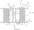
- FIG. 2 illustrates an apparatus 10A, in cross-section, which comprises a variation of the arrangement shown in Figure 1 .
- a detonator not shown, is connected to an end of a signal-transmitting conductor 14 which is coiled on the hub 24.
- the hub is enlarged in that it defines an annular cylindrical cavity 50 in which components, corresponding to those listed in connection with the connector 40, are mounted.
- the tubular hub contains a transmitter/receiver module 52, a battery 54 and a processor 56.
- Two light emitting devices, e.g. LED's, 58 and 60 which are mounted to the discs 28 and 30 respectively can be powered under controlled conditions by energy drawn from the battery 54.
- a photo-voltaic cell 64 which is mounted to one of the discs is used to recharge the battery 54, when the cell is exposed to sunlight conditions.
- Connector formations 68 are provided on one of the discs. These connector formations duplicate connector formations which are provided on the connector 40. In essence therefore the connector 40 which is shown in Figure1 is wholly mounted to the spool 12. Additionally the light-emitting diodes 58 and 60 mounted to the discs are coupled to the connector components.
- the apparatus 10A is used in the same way as the apparatus 10 in that the conductor 14 is deployed from the spool to a required length as may be necessary to position a detonator, which is attached to the connector, at a desired position inside a borehole.
- a short axle (not shown) placed through the passage 26 allows the spool to be rotated thereby to facilitate uncoiling of the conductor. Connections in the blasting system are then made via the formations 68.
- the light-emitting diodes 58 and 60 can be caused to pulse so that physical indications are given of the location of the spool.
- a radio signal can be transmitted so that the spool can easily be located. This radio signal can also carry identity data pertaining at least to the detonator which is attached to the conductor.
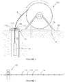
- FIG. 3 illustrates a variation 10B of the apparatus of the invention.
- a spool 12A is mounted for rotation about an axle 70 which in turn is supported on a stand 74 which is fixed, using suitable fasteners 76, to the ground 80 adjacent a borehole 82.
- the conductor 14 passes through a guide 84 which is mounted to the stand 74.
- a further guide 86 is used to position the conductor correctly in relation to the borehole 82.
- the apparatus 10B includes an annular, centrally located, cylindrical cavity 90 which has a number of inwardly directed formations 94 on an inner surface.
- the axle 70 has a number of flexible or resilient leaves 96 which are brought into contact with the various formations 94. The arrangement is such that the leaves prevent free rotation of the cavity 90 about the axle 26.
- the flexible leaves are deflected, automatically, by the formations 94 and a degree of rotation of the spool takes place which causes the tensile force in the conductor to be reduced. If the tensile force increases then the release mechanism again functions and the spool can rotate, in the manner described, through a limited arc to reduce the magnitude of the tensile force prevailing in the conductor.
- Figure 4 shows an apparatus 10C which bears a number of similarities to the apparatus 10B.
- the release mechanism 88 is replaced by a movement-restricting device 100 which, in this example, is mounted on the ground at a mouth of the borehole 82.
- the device 100 can take on different forms and conveniently comprises a plate 106 with a compressible friction component 110 mounted to the plate.
- the conductor 14 passes through a hole in the component 110 and in the plate 106. If the component 110 is compressed in a radial direction, as is indicated by arrows 112, then a frictional force is exerted on an outer surface of the conductor which tends to lock the conductor to the plate. The force is such that free movement of the conductor through the plate is inhibited.
- the apparatus of the invention can also include a measuring device which facilitates a determination of a length of the conductor 14 which is placed into a borehole 82.
- the conductor 14 can include a plurality of formations 116 at spaced apart and regular intervals.
- the formations pass a sensor 120 which detects, physically, the presence of the enlarged formations and a count is established of the number of formations which pass the sensor 120. The depth to which the detonator is placed into the borehole can then be assessed.
- the formations are replaced by markings on the conductor 14 and an optically based sensor 120 then detects the passage of the markings in a contactless manner which enables a count to be kept of the depth to which a detonator is placed in a borehole.
Landscapes
- Engineering & Computer Science (AREA)
- General Engineering & Computer Science (AREA)
- Life Sciences & Earth Sciences (AREA)
- General Life Sciences & Earth Sciences (AREA)
- Geophysics And Detection Of Objects (AREA)
- Arrangements For Transmission Of Measured Signals (AREA)
- Measuring Fluid Pressure (AREA)
- Storing, Repeated Paying-Out, And Re-Storing Of Elongated Articles (AREA)
- Storage Of Web-Like Or Filamentary Materials (AREA)
- Surgical Instruments (AREA)
- Wire Bonding (AREA)
Claims (7)
- Appareil (10) destiné à être utilisé dans un système de dynamitage qui comprend une bobine (12) avec un moyeu, des premier et second disques (28, 30) qui sont montés sur le moyeu, un conducteur flexible allongé (14) de transmission de signaux qui a une première extrémité (18) et une seconde extrémité (38) et qui est enroulé sur le moyeu (24) entre les disques, au moins un premier détonateur (16) qui est connecté au conducteur de transmission de signaux (14) à ou près de la première extrémité (18), un connecteur qui est connecté ou exposé au conducteur de transmission de signaux (14) à ou près de la seconde extrémité (38), caractérisé en ce que le conducteur de transmission de signaux (14) comprend des marquages ou des formations espacé(e)s et la bobine (12) comprend un capteur (120), réagissant au passage d'un marquage ou d'une formation devant le capteur (120) pour produire une mesure d'une longueur du conducteur (14) de transmission de signaux qui est déroulée du moyeu (24) et un mécanisme de libération (88) qui, en utilisation, permet un degré de rotation de la bobine (12) ou un mouvement du conducteur (14) lorsqu'une force de traction (F) exercée sur le conducteur (14) augmente au-dessus d'un niveau prédéterminé, pour réduire ainsi le niveau de la force de traction (F) exercée sur le conducteur (14), le connecteur (40) comprenant, entièrement situés à l'intérieur du moyeu (24), un module émetteur/récepteur (52), une batterie (54) et un processeur (56), et des formations de connexion (68), et en ce que la communication avec un dispositif de commande peut être établie par l'intermédiaire des formations de connexion (68) ou par l'intermédiaire du module émetteur/récepteur (52).
- Appareil selon la revendication 1, le conducteur de transmission de signaux (14) étant choisi parmi les éléments suivants : des fils électriques, un câble à fibres optiques et un tube à choc.
- Appareil selon la revendication 1, qui comprend au moins un dispositif électroluminescent (58 ; 60) qui est couplé au connecteur et qui est utilisé pour indiquer l'emplacement physique de la bobine (12).
- Appareil selon la revendication 1, comprenant au moins un mécanisme de communication qui est utilisé pour indiquer l'emplacement physique de la bobine.
- Appareil selon la revendication 4, le mécanisme de communication (52) étant utilisé pour communiquer une identité qui est associée de manière unique à l'appareil ou au détonateur (16).
- Appareil selon la revendication 4, le mécanisme de communication (52) étant un dispositif bidirectionnel qui est capable de recevoir un signal et, en réponse à la réception d'un tel signal, de transmettre une réponse.
- Appareil selon la revendication 1, qui comprend au moins un capteur (120) qui est sensible au moins aux conditions environnementales ou de fonctionnement, comprenant la température, les vibrations, un ou plusieurs produits chimiques spécifiques.
Applications Claiming Priority (2)
| Application Number | Priority Date | Filing Date | Title |
|---|---|---|---|
| ZA201602408 | 2016-04-11 | ||
| PCT/ZA2017/050020 WO2017181207A1 (fr) | 2016-04-11 | 2017-04-07 | Appareil destiné à être utilisé dans un système de dynamitage |
Publications (2)
| Publication Number | Publication Date |
|---|---|
| EP3442892A1 EP3442892A1 (fr) | 2019-02-20 |
| EP3442892B1 true EP3442892B1 (fr) | 2020-06-03 |
Family
ID=59009821
Family Applications (1)
| Application Number | Title | Priority Date | Filing Date |
|---|---|---|---|
| EP17728035.1A Active EP3442892B1 (fr) | 2016-04-11 | 2017-04-07 | Appareil destiné à être utilisé dans un système de dynamitage |
Country Status (11)
| Country | Link |
|---|---|
| US (1) | US11453569B2 (fr) |
| EP (1) | EP3442892B1 (fr) |
| AU (1) | AU2017248852B2 (fr) |
| BR (1) | BR112018070958B1 (fr) |
| CA (1) | CA3020497C (fr) |
| CL (1) | CL2018002910A1 (fr) |
| CO (1) | CO2018011628A2 (fr) |
| ES (1) | ES2812705T3 (fr) |
| MX (1) | MX2018012384A (fr) |
| WO (1) | WO2017181207A1 (fr) |
| ZA (1) | ZA201806670B (fr) |
Families Citing this family (10)
| Publication number | Priority date | Publication date | Assignee | Title |
|---|---|---|---|---|
| CA3105119A1 (fr) * | 2018-06-29 | 2020-01-02 | Newcrest Mining Limited | Ensemble survolteur |
| AU2019296518B2 (en) | 2018-06-29 | 2025-04-10 | Olitek Pty Ltd | A mining vehicle |
| KR102129308B1 (ko) * | 2018-12-19 | 2020-07-02 | 주식회사 한화 | 발파 시스템용 전자식 뇌관 장치 |
| KR20200077235A (ko) * | 2018-12-20 | 2020-06-30 | 주식회사 한화 | 전자식 뇌관 장치를 포함하는 발파 시스템 |
| KR102444100B1 (ko) * | 2019-12-10 | 2022-09-15 | 주식회사 한화 | 지면에 고정이 가능한 발파 시스템용 전자식 뇌관 장치 및 이를 이용한 발파 시스템 |
| DE102021111767A1 (de) | 2021-05-06 | 2022-11-10 | Maschinenfabrik Rieter Ag | Verfahren zum Markieren von Hülsen sowie Hülse |
| FR3126484B1 (fr) * | 2021-09-01 | 2023-09-01 | Davey Bickford | Bobine de détonateur électronique et détonateur comprenant une telle bobine |
| WO2023049943A1 (fr) * | 2021-09-22 | 2023-03-30 | Detnet South Africa (Pty) Ltd | Déploiement d'un ensemble détonateur |
| CA3233975A1 (fr) * | 2021-10-07 | 2023-04-13 | Anh Tuan Nguyen | Systeme et procede/processus de dynamitage commercial |
| WO2024259542A1 (fr) | 2023-06-23 | 2024-12-26 | Enaex Servicios S.A | Système de distribution d'amorces dans des trous de mine en vue d'opérations minières |
Family Cites Families (22)
| Publication number | Priority date | Publication date | Assignee | Title |
|---|---|---|---|---|
| GB191211517A (en) * | 1912-05-15 | 1913-01-09 | Arthur Shore | New or Improved Means for Supporting the Bobbins in the Creels of Spinning and Twisting or like Machines. |
| GB191511517A (en) | 1915-08-10 | 1916-08-10 | John Thomas Smith | A New and Improved Manner of Washing or Eliminating Chemicals from Photographic Plates, Films Prints or such like Articles. |
| US2021632A (en) * | 1934-01-29 | 1935-11-19 | American Glycerin Company | Method of and apparatus for placing explosive charges |
| US2069695A (en) * | 1935-03-27 | 1937-02-02 | Frank W Brown | Safety reel for a blasting cable |
| US2089981A (en) * | 1936-01-17 | 1937-08-17 | Price Robert | Blasting apparatus |
| US2205056A (en) * | 1938-04-14 | 1940-06-18 | Atkins George Thornton | Safety reel for blasting cables |
| US2173777A (en) * | 1938-08-25 | 1939-09-19 | Eads William Preston | Circuit closing device |
| US2267845A (en) * | 1940-11-15 | 1941-12-30 | Henry M Stephens | Safety blasting cable spool |
| US3686448A (en) * | 1970-08-06 | 1972-08-22 | Jerome S Brower | Safety reel |
| US4166418A (en) * | 1977-05-23 | 1979-09-04 | Austin Powder Company | Time delay primer and method of making same |
| US4880182A (en) * | 1988-03-25 | 1989-11-14 | Stanley Gelfman | Cable reel |
| AU2003200490B2 (en) * | 2002-02-20 | 2008-05-08 | Rocktek Ltd. | Apparatus and method for fracturing a hard material |
| US20040102870A1 (en) | 2002-11-26 | 2004-05-27 | Andersen Scott Paul | RFID enabled paper rolls and system and method for tracking inventory |
| US7086335B2 (en) * | 2003-03-07 | 2006-08-08 | Shock Tube Systems, Inc. | Redundant signal transmission system and deployment means |
| US20040255810A1 (en) * | 2003-03-28 | 2004-12-23 | O'brien John P. | Detonating cord inventory control marking system |
| PE20110493A1 (es) * | 2009-12-30 | 2011-07-22 | Ind Minco S A C | Sistema de retraso de alta precision |
| EP2472056B1 (fr) * | 2010-12-30 | 2016-10-12 | Maxamcorp Holding, S.L. | Système d'inspection de trou de forage et procédé de chargement des trous de mine |
| ZA201404847B (en) | 2013-05-30 | 2015-07-29 | Ael Mining Services Ltd | Shock tube initiator |
| CA2955262C (fr) * | 2014-08-29 | 2018-10-16 | Hunting Titan, Inc. | Ensemble explosif a haute tension permettant des detonations de fond de trou |
| WO2016086242A2 (fr) | 2014-11-28 | 2016-06-02 | Detnet South Africa (Pty) Ltd | Amorçage de détonateur électronique |
| AU2017248851B2 (en) | 2016-04-11 | 2022-01-06 | Detnet South Africa (Pty) Ltd | Spool |
| CN109238063B (zh) * | 2018-11-29 | 2021-05-25 | 中钢集团马鞍山矿山研究总院股份有限公司 | 露天爆破工程用的智能化、环保型炮孔排水车 |
-
2017
- 2017-04-07 EP EP17728035.1A patent/EP3442892B1/fr active Active
- 2017-04-07 US US16/092,536 patent/US11453569B2/en active Active
- 2017-04-07 AU AU2017248852A patent/AU2017248852B2/en active Active
- 2017-04-07 MX MX2018012384A patent/MX2018012384A/es unknown
- 2017-04-07 ES ES17728035T patent/ES2812705T3/es active Active
- 2017-04-07 CA CA3020497A patent/CA3020497C/fr active Active
- 2017-04-07 WO PCT/ZA2017/050020 patent/WO2017181207A1/fr not_active Ceased
- 2017-04-07 BR BR112018070958-1A patent/BR112018070958B1/pt active IP Right Grant
-
2018
- 2018-10-08 ZA ZA2018/06670A patent/ZA201806670B/en unknown
- 2018-10-11 CL CL2018002910A patent/CL2018002910A1/es unknown
- 2018-10-29 CO CONC2018/0011628A patent/CO2018011628A2/es unknown
Non-Patent Citations (1)
| Title |
|---|
| None * |
Also Published As
| Publication number | Publication date |
|---|---|
| US11453569B2 (en) | 2022-09-27 |
| CA3020497A1 (fr) | 2017-10-19 |
| BR112018070958A2 (pt) | 2019-01-29 |
| BR112018070958B1 (pt) | 2022-07-05 |
| CL2018002910A1 (es) | 2019-03-08 |
| US20190119066A1 (en) | 2019-04-25 |
| WO2017181207A1 (fr) | 2017-10-19 |
| AU2017248852B2 (en) | 2022-12-15 |
| AU2017248852A1 (en) | 2018-11-15 |
| EP3442892A1 (fr) | 2019-02-20 |
| ZA201806670B (en) | 2019-06-26 |
| CA3020497C (fr) | 2020-07-21 |
| ES2812705T3 (es) | 2021-03-18 |
| MX2018012384A (es) | 2019-02-20 |
| CO2018011628A2 (es) | 2018-11-13 |
Similar Documents
| Publication | Publication Date | Title |
|---|---|---|
| EP3442892B1 (fr) | Appareil destiné à être utilisé dans un système de dynamitage | |
| EP2104417B1 (fr) | Méthode pour déterminer la position d'un rover par rapport à une frontière, et système de confinement d'animaux associé | |
| EP2702349B1 (fr) | Détonateurs sans fil à détection d'état et leur utilisation | |
| US9709373B2 (en) | Wireless detonation system, wireless detonation method, and detonator and explosive unit used in same | |
| AU2015353394B2 (en) | Electronic detonator initiation | |
| US9279645B2 (en) | Electronic detonator | |
| EP3825514A1 (fr) | Unité de forage de roches et procédé de chargement de trous forés | |
| EP4185836A1 (fr) | Systèmes, procédés et dispositifs pour des opérations de dynamitage commercial | |
| EP4222443A1 (fr) | Ensemble détonateur | |
| OA18901A (en) | Apparatus for use in a blasting system. | |
| US20230316010A1 (en) | Power source-less sensor device |
Legal Events
| Date | Code | Title | Description |
|---|---|---|---|
| STAA | Information on the status of an ep patent application or granted ep patent |
Free format text: STATUS: UNKNOWN |
|
| STAA | Information on the status of an ep patent application or granted ep patent |
Free format text: STATUS: THE INTERNATIONAL PUBLICATION HAS BEEN MADE |
|
| PUAI | Public reference made under article 153(3) epc to a published international application that has entered the european phase |
Free format text: ORIGINAL CODE: 0009012 |
|
| STAA | Information on the status of an ep patent application or granted ep patent |
Free format text: STATUS: REQUEST FOR EXAMINATION WAS MADE |
|
| 17P | Request for examination filed |
Effective date: 20181011 |
|
| AK | Designated contracting states |
Kind code of ref document: A1 Designated state(s): AL AT BE BG CH CY CZ DE DK EE ES FI FR GB GR HR HU IE IS IT LI LT LU LV MC MK MT NL NO PL PT RO RS SE SI SK SM TR |
|
| AX | Request for extension of the european patent |
Extension state: BA ME |
|
| DAV | Request for validation of the european patent (deleted) | ||
| DAX | Request for extension of the european patent (deleted) | ||
| STAA | Information on the status of an ep patent application or granted ep patent |
Free format text: STATUS: EXAMINATION IS IN PROGRESS |
|
| 17Q | First examination report despatched |
Effective date: 20191021 |
|
| GRAP | Despatch of communication of intention to grant a patent |
Free format text: ORIGINAL CODE: EPIDOSNIGR1 |
|
| STAA | Information on the status of an ep patent application or granted ep patent |
Free format text: STATUS: GRANT OF PATENT IS INTENDED |
|
| INTG | Intention to grant announced |
Effective date: 20200206 |
|
| GRAS | Grant fee paid |
Free format text: ORIGINAL CODE: EPIDOSNIGR3 |
|
| GRAA | (expected) grant |
Free format text: ORIGINAL CODE: 0009210 |
|
| STAA | Information on the status of an ep patent application or granted ep patent |
Free format text: STATUS: THE PATENT HAS BEEN GRANTED |
|
| AK | Designated contracting states |
Kind code of ref document: B1 Designated state(s): AL AT BE BG CH CY CZ DE DK EE ES FI FR GB GR HR HU IE IS IT LI LT LU LV MC MK MT NL NO PL PT RO RS SE SI SK SM TR |
|
| REG | Reference to a national code |
Ref country code: GB Ref legal event code: FG4D |
|
| REG | Reference to a national code |
Ref country code: CH Ref legal event code: EP Ref country code: AT Ref legal event code: REF Ref document number: 1276808 Country of ref document: AT Kind code of ref document: T Effective date: 20200615 |
|
| REG | Reference to a national code |
Ref country code: DE Ref legal event code: R096 Ref document number: 602017017689 Country of ref document: DE |
|
| REG | Reference to a national code |
Ref country code: SE Ref legal event code: TRGR |
|
| REG | Reference to a national code |
Ref country code: LT Ref legal event code: MG4D |
|
| PG25 | Lapsed in a contracting state [announced via postgrant information from national office to epo] |
Ref country code: GR Free format text: LAPSE BECAUSE OF FAILURE TO SUBMIT A TRANSLATION OF THE DESCRIPTION OR TO PAY THE FEE WITHIN THE PRESCRIBED TIME-LIMIT Effective date: 20200904 Ref country code: NO Free format text: LAPSE BECAUSE OF FAILURE TO SUBMIT A TRANSLATION OF THE DESCRIPTION OR TO PAY THE FEE WITHIN THE PRESCRIBED TIME-LIMIT Effective date: 20200903 Ref country code: LT Free format text: LAPSE BECAUSE OF FAILURE TO SUBMIT A TRANSLATION OF THE DESCRIPTION OR TO PAY THE FEE WITHIN THE PRESCRIBED TIME-LIMIT Effective date: 20200603 Ref country code: FI Free format text: LAPSE BECAUSE OF FAILURE TO SUBMIT A TRANSLATION OF THE DESCRIPTION OR TO PAY THE FEE WITHIN THE PRESCRIBED TIME-LIMIT Effective date: 20200603 |
|
| REG | Reference to a national code |
Ref country code: NL Ref legal event code: MP Effective date: 20200603 |
|
| PG25 | Lapsed in a contracting state [announced via postgrant information from national office to epo] |
Ref country code: HR Free format text: LAPSE BECAUSE OF FAILURE TO SUBMIT A TRANSLATION OF THE DESCRIPTION OR TO PAY THE FEE WITHIN THE PRESCRIBED TIME-LIMIT Effective date: 20200603 Ref country code: LV Free format text: LAPSE BECAUSE OF FAILURE TO SUBMIT A TRANSLATION OF THE DESCRIPTION OR TO PAY THE FEE WITHIN THE PRESCRIBED TIME-LIMIT Effective date: 20200603 Ref country code: BG Free format text: LAPSE BECAUSE OF FAILURE TO SUBMIT A TRANSLATION OF THE DESCRIPTION OR TO PAY THE FEE WITHIN THE PRESCRIBED TIME-LIMIT Effective date: 20200903 Ref country code: RS Free format text: LAPSE BECAUSE OF FAILURE TO SUBMIT A TRANSLATION OF THE DESCRIPTION OR TO PAY THE FEE WITHIN THE PRESCRIBED TIME-LIMIT Effective date: 20200603 |
|
| REG | Reference to a national code |
Ref country code: AT Ref legal event code: MK05 Ref document number: 1276808 Country of ref document: AT Kind code of ref document: T Effective date: 20200603 |
|
| PG25 | Lapsed in a contracting state [announced via postgrant information from national office to epo] |
Ref country code: AL Free format text: LAPSE BECAUSE OF FAILURE TO SUBMIT A TRANSLATION OF THE DESCRIPTION OR TO PAY THE FEE WITHIN THE PRESCRIBED TIME-LIMIT Effective date: 20200603 Ref country code: NL Free format text: LAPSE BECAUSE OF FAILURE TO SUBMIT A TRANSLATION OF THE DESCRIPTION OR TO PAY THE FEE WITHIN THE PRESCRIBED TIME-LIMIT Effective date: 20200603 |
|
| PG25 | Lapsed in a contracting state [announced via postgrant information from national office to epo] |
Ref country code: CZ Free format text: LAPSE BECAUSE OF FAILURE TO SUBMIT A TRANSLATION OF THE DESCRIPTION OR TO PAY THE FEE WITHIN THE PRESCRIBED TIME-LIMIT Effective date: 20200603 Ref country code: SM Free format text: LAPSE BECAUSE OF FAILURE TO SUBMIT A TRANSLATION OF THE DESCRIPTION OR TO PAY THE FEE WITHIN THE PRESCRIBED TIME-LIMIT Effective date: 20200603 Ref country code: EE Free format text: LAPSE BECAUSE OF FAILURE TO SUBMIT A TRANSLATION OF THE DESCRIPTION OR TO PAY THE FEE WITHIN THE PRESCRIBED TIME-LIMIT Effective date: 20200603 Ref country code: RO Free format text: LAPSE BECAUSE OF FAILURE TO SUBMIT A TRANSLATION OF THE DESCRIPTION OR TO PAY THE FEE WITHIN THE PRESCRIBED TIME-LIMIT Effective date: 20200603 Ref country code: AT Free format text: LAPSE BECAUSE OF FAILURE TO SUBMIT A TRANSLATION OF THE DESCRIPTION OR TO PAY THE FEE WITHIN THE PRESCRIBED TIME-LIMIT Effective date: 20200603 Ref country code: IT Free format text: LAPSE BECAUSE OF FAILURE TO SUBMIT A TRANSLATION OF THE DESCRIPTION OR TO PAY THE FEE WITHIN THE PRESCRIBED TIME-LIMIT Effective date: 20200603 Ref country code: PT Free format text: LAPSE BECAUSE OF FAILURE TO SUBMIT A TRANSLATION OF THE DESCRIPTION OR TO PAY THE FEE WITHIN THE PRESCRIBED TIME-LIMIT Effective date: 20201006 |
|
| PG25 | Lapsed in a contracting state [announced via postgrant information from national office to epo] |
Ref country code: PL Free format text: LAPSE BECAUSE OF FAILURE TO SUBMIT A TRANSLATION OF THE DESCRIPTION OR TO PAY THE FEE WITHIN THE PRESCRIBED TIME-LIMIT Effective date: 20200603 Ref country code: SK Free format text: LAPSE BECAUSE OF FAILURE TO SUBMIT A TRANSLATION OF THE DESCRIPTION OR TO PAY THE FEE WITHIN THE PRESCRIBED TIME-LIMIT Effective date: 20200603 Ref country code: IS Free format text: LAPSE BECAUSE OF FAILURE TO SUBMIT A TRANSLATION OF THE DESCRIPTION OR TO PAY THE FEE WITHIN THE PRESCRIBED TIME-LIMIT Effective date: 20201003 |
|
| REG | Reference to a national code |
Ref country code: DE Ref legal event code: R097 Ref document number: 602017017689 Country of ref document: DE |
|
| REG | Reference to a national code |
Ref country code: ES Ref legal event code: FG2A Ref document number: 2812705 Country of ref document: ES Kind code of ref document: T3 Effective date: 20210318 |
|
| PLBE | No opposition filed within time limit |
Free format text: ORIGINAL CODE: 0009261 |
|
| STAA | Information on the status of an ep patent application or granted ep patent |
Free format text: STATUS: NO OPPOSITION FILED WITHIN TIME LIMIT |
|
| PG25 | Lapsed in a contracting state [announced via postgrant information from national office to epo] |
Ref country code: DK Free format text: LAPSE BECAUSE OF FAILURE TO SUBMIT A TRANSLATION OF THE DESCRIPTION OR TO PAY THE FEE WITHIN THE PRESCRIBED TIME-LIMIT Effective date: 20200603 |
|
| 26N | No opposition filed |
Effective date: 20210304 |
|
| PG25 | Lapsed in a contracting state [announced via postgrant information from national office to epo] |
Ref country code: SI Free format text: LAPSE BECAUSE OF FAILURE TO SUBMIT A TRANSLATION OF THE DESCRIPTION OR TO PAY THE FEE WITHIN THE PRESCRIBED TIME-LIMIT Effective date: 20200603 |
|
| PG25 | Lapsed in a contracting state [announced via postgrant information from national office to epo] |
Ref country code: MC Free format text: LAPSE BECAUSE OF FAILURE TO SUBMIT A TRANSLATION OF THE DESCRIPTION OR TO PAY THE FEE WITHIN THE PRESCRIBED TIME-LIMIT Effective date: 20200603 |
|
| PG25 | Lapsed in a contracting state [announced via postgrant information from national office to epo] |
Ref country code: LU Free format text: LAPSE BECAUSE OF NON-PAYMENT OF DUE FEES Effective date: 20210407 |
|
| REG | Reference to a national code |
Ref country code: BE Ref legal event code: MM Effective date: 20210430 |
|
| PG25 | Lapsed in a contracting state [announced via postgrant information from national office to epo] |
Ref country code: FR Free format text: LAPSE BECAUSE OF NON-PAYMENT OF DUE FEES Effective date: 20210430 Ref country code: CH Free format text: LAPSE BECAUSE OF NON-PAYMENT OF DUE FEES Effective date: 20210430 Ref country code: LI Free format text: LAPSE BECAUSE OF NON-PAYMENT OF DUE FEES Effective date: 20210430 |
|
| PG25 | Lapsed in a contracting state [announced via postgrant information from national office to epo] |
Ref country code: IE Free format text: LAPSE BECAUSE OF NON-PAYMENT OF DUE FEES Effective date: 20210407 |
|
| PG25 | Lapsed in a contracting state [announced via postgrant information from national office to epo] |
Ref country code: IS Free format text: LAPSE BECAUSE OF FAILURE TO SUBMIT A TRANSLATION OF THE DESCRIPTION OR TO PAY THE FEE WITHIN THE PRESCRIBED TIME-LIMIT Effective date: 20201003 |
|
| REG | Reference to a national code |
Ref country code: ES Ref legal event code: FD2A Effective date: 20220629 |
|
| PG25 | Lapsed in a contracting state [announced via postgrant information from national office to epo] |
Ref country code: ES Free format text: LAPSE BECAUSE OF NON-PAYMENT OF DUE FEES Effective date: 20210408 Ref country code: BE Free format text: LAPSE BECAUSE OF NON-PAYMENT OF DUE FEES Effective date: 20210430 |
|
| PG25 | Lapsed in a contracting state [announced via postgrant information from national office to epo] |
Ref country code: CY Free format text: LAPSE BECAUSE OF FAILURE TO SUBMIT A TRANSLATION OF THE DESCRIPTION OR TO PAY THE FEE WITHIN THE PRESCRIBED TIME-LIMIT Effective date: 20200603 |
|
| PG25 | Lapsed in a contracting state [announced via postgrant information from national office to epo] |
Ref country code: HU Free format text: LAPSE BECAUSE OF FAILURE TO SUBMIT A TRANSLATION OF THE DESCRIPTION OR TO PAY THE FEE WITHIN THE PRESCRIBED TIME-LIMIT; INVALID AB INITIO Effective date: 20170407 |
|
| PG25 | Lapsed in a contracting state [announced via postgrant information from national office to epo] |
Ref country code: MK Free format text: LAPSE BECAUSE OF FAILURE TO SUBMIT A TRANSLATION OF THE DESCRIPTION OR TO PAY THE FEE WITHIN THE PRESCRIBED TIME-LIMIT Effective date: 20200603 |
|
| PG25 | Lapsed in a contracting state [announced via postgrant information from national office to epo] |
Ref country code: TR Free format text: LAPSE BECAUSE OF FAILURE TO SUBMIT A TRANSLATION OF THE DESCRIPTION OR TO PAY THE FEE WITHIN THE PRESCRIBED TIME-LIMIT Effective date: 20200603 |
|
| PGFP | Annual fee paid to national office [announced via postgrant information from national office to epo] |
Ref country code: DE Payment date: 20240418 Year of fee payment: 8 |
|
| PG25 | Lapsed in a contracting state [announced via postgrant information from national office to epo] |
Ref country code: MT Free format text: LAPSE BECAUSE OF FAILURE TO SUBMIT A TRANSLATION OF THE DESCRIPTION OR TO PAY THE FEE WITHIN THE PRESCRIBED TIME-LIMIT Effective date: 20200603 |
|
| PGFP | Annual fee paid to national office [announced via postgrant information from national office to epo] |
Ref country code: SE Payment date: 20250423 Year of fee payment: 9 |
|
| REG | Reference to a national code |
Ref country code: DE Ref legal event code: R119 Ref document number: 602017017689 Country of ref document: DE |
|
| PG25 | Lapsed in a contracting state [announced via postgrant information from national office to epo] |
Ref country code: DE Free format text: LAPSE BECAUSE OF NON-PAYMENT OF DUE FEES Effective date: 20251104 |
|
| PGFP | Annual fee paid to national office [announced via postgrant information from national office to epo] |
Ref country code: GB Payment date: 20260330 Year of fee payment: 10 |