EP3443193B1 - Appareil de tarière de sol encastré pour évaluations archéologiques et son procédé de fonctionnement - Google Patents
Appareil de tarière de sol encastré pour évaluations archéologiques et son procédé de fonctionnement Download PDFInfo
- Publication number
- EP3443193B1 EP3443193B1 EP17864759.0A EP17864759A EP3443193B1 EP 3443193 B1 EP3443193 B1 EP 3443193B1 EP 17864759 A EP17864759 A EP 17864759A EP 3443193 B1 EP3443193 B1 EP 3443193B1
- Authority
- EP
- European Patent Office
- Prior art keywords
- soil
- auger
- encased
- casing
- auger apparatus
- Prior art date
- Legal status (The legal status is an assumption and is not a legal conclusion. Google has not performed a legal analysis and makes no representation as to the accuracy of the status listed.)
- Active
Links
Images



Classifications
-
- G—PHYSICS
- G01—MEASURING; TESTING
- G01N—INVESTIGATING OR ANALYSING MATERIALS BY DETERMINING THEIR CHEMICAL OR PHYSICAL PROPERTIES
- G01N1/00—Sampling; Preparing specimens for investigation
- G01N1/02—Devices for withdrawing samples
- G01N1/04—Devices for withdrawing samples in the solid state, e.g. by cutting
- G01N1/08—Devices for withdrawing samples in the solid state, e.g. by cutting involving an extracting tool, e.g. core bit
-
- E—FIXED CONSTRUCTIONS
- E02—HYDRAULIC ENGINEERING; FOUNDATIONS; SOIL SHIFTING
- E02D—FOUNDATIONS; EXCAVATIONS; EMBANKMENTS; UNDERGROUND OR UNDERWATER STRUCTURES
- E02D1/00—Investigation of foundation soil in situ
- E02D1/02—Investigation of foundation soil in situ before construction work
- E02D1/04—Sampling of soil
-
- E—FIXED CONSTRUCTIONS
- E21—EARTH OR ROCK DRILLING; MINING
- E21B—EARTH OR ROCK DRILLING; OBTAINING OIL, GAS, WATER, SOLUBLE OR MELTABLE MATERIALS OR A SLURRY OF MINERALS FROM WELLS
- E21B10/00—Drill bits
- E21B10/44—Bits with helical conveying portion, e.g. screw type bits; Augers with leading portion or with detachable parts
-
- E—FIXED CONSTRUCTIONS
- E21—EARTH OR ROCK DRILLING; MINING
- E21B—EARTH OR ROCK DRILLING; OBTAINING OIL, GAS, WATER, SOLUBLE OR MELTABLE MATERIALS OR A SLURRY OF MINERALS FROM WELLS
- E21B49/00—Testing the nature of borehole walls; Formation testing; Methods or apparatus for obtaining samples of soil or well fluids, specially adapted to earth drilling or wells
- E21B49/02—Testing the nature of borehole walls; Formation testing; Methods or apparatus for obtaining samples of soil or well fluids, specially adapted to earth drilling or wells by mechanically taking samples of the soil
-
- E—FIXED CONSTRUCTIONS
- E21—EARTH OR ROCK DRILLING; MINING
- E21B—EARTH OR ROCK DRILLING; OBTAINING OIL, GAS, WATER, SOLUBLE OR MELTABLE MATERIALS OR A SLURRY OF MINERALS FROM WELLS
- E21B7/00—Special methods or apparatus for drilling
- E21B7/003—Drilling with mechanical conveying means
- E21B7/005—Drilling with mechanical conveying means with helical conveying means
-
- E—FIXED CONSTRUCTIONS
- E21—EARTH OR ROCK DRILLING; MINING
- E21B—EARTH OR ROCK DRILLING; OBTAINING OIL, GAS, WATER, SOLUBLE OR MELTABLE MATERIALS OR A SLURRY OF MINERALS FROM WELLS
- E21B7/00—Special methods or apparatus for drilling
- E21B7/20—Driving or forcing casings or pipes into boreholes, e.g. sinking; Simultaneously drilling and casing boreholes
- E21B7/201—Driving or forcing casings or pipes into boreholes, e.g. sinking; Simultaneously drilling and casing boreholes with helical conveying means
-
- G—PHYSICS
- G01—MEASURING; TESTING
- G01N—INVESTIGATING OR ANALYSING MATERIALS BY DETERMINING THEIR CHEMICAL OR PHYSICAL PROPERTIES
- G01N33/00—Investigating or analysing materials by specific methods not covered by groups G01N1/00 - G01N31/00
- G01N33/24—Earth materials
Definitions
- the present invention relates to systematic archaeological test pitting, and more particularly, to an encased soil auger apparatus for mechanical extraction and processing of soil for archeological assessments and a method of operating the same.
- test pits Present-day archaeological testing of areas of archaeological potential is conducted by manually excavating numerous test pits - typically, several hundred test pits are excavated for larger scale projects - arranged in a geo-referenced grid covering the area.
- the standard size of the test pits used by archaeologists to test the ground for archaeological remains is 50 cm by 50 cm cross-section and depth of 120 cm.
- the soil extracted from the test pits is then, typically manually, screened for archaeological remains before the test pits are back filled.
- test pits are not of the same size, substantially reducing the accuracy of the testing due to the non-uniformity of the test pits.
- Another problem of manual testing is "spill-in" of sediments surrounding the test pits - in particular, gravel rich soil - causing cross-contamination of the extracted soil, further reducing the accuracy of the testing.
- tubular soil augers as disclosed, for example, in US Patents 4,653,336 and 8,365,638 , increases the sample retaining capacity of the auger, the size of the auger is still substantially limited, as well as the "spill-in" effect is still encountered.
- US 2,735,703 teaches a drilling auger for excavating a water well. Apertures are disposed in a barrel of the drilling auger in order to drain water from the soil contained in the barrel.
- EP 1 905 945 A1 teaches a drilling auger contained in an auger casing.
- US 2008/0047757 A1 teaches a method for producing a borehole in which a drill pipe and a conveyor screw inside the drill pipe are set into rotation and into the soil. Soil material is loosened by means of at least one main cutting edge.
- US 4,228,862 teaches a cylindrical drilling tool having one end coupled to a motor assembly for rotating the tool by way of an elongate rotatable sleeve.
- a hydraulic jack is disposed in the sleeve for rotation therewith.
- the piston rod of the jack extends longitudinally of the drilling tool and carries a valve-action member arranged to allow drilled material to enter the drilling tool and to retain the material therein.
- the piston rod is movable longitudinally relative to said tool for the discharge of said material.
- US 2006/0060386 A1 teaches a pile boring tool for producing a pile bore with a central tube coaxial to the boring axis, at least one edge directed transversely to the boring axis and on which is provided a plurality of cutting teeth and a conveying mechanism for receiving and/or conveying away soil removed by the cutting teeth.
- an encased soil auger apparatus according to claim 1.
- Another aspect of the invention provides a method of extracting and screening soil according to claim 9. Certain more specific aspects of the invention are set out in the dependent claims.
- a further advantage of the present invention is that it provides a method of operating an encased soil auger apparatus for mechanical extraction and processing of soil for archeological assessments that enables soil extraction and soil screening using the same apparatus.
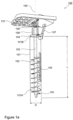
- an encased soil auger apparatus 100 according to a reference example is provided.
- the encased soil auger apparatus 100 comprises an auger casing 101 forming a hollow cylindrical body.
- a wall of the auger casing 101 has a plurality of openings 106 disposed therein having a predetermined size for enabling passage of particles therethrough.
- a soil auger 102 having a helical screw blade is disposed in the auger casing 101 in a coaxial fashion - longitudinal axis 150.
- a soil engaging end portion 105 of the auger 102 protrudes a first end 101A of the auger casing 101.
- a second end 101B of the auger casing 101 is pivotally movable mounted to an auger quick mount plate 110 via split end plate and mounting ring 104, pivoting control arms 108, and auger support bracket 107, as will be described in more detail hereinbelow with reference to Figures 2a to 2f .
- the auger support bracket 107 articulates the encased soil auger apparatus 100 enabling proper vertical orientation of the same for drilling.
- Auger drive shaft 103 is connected to auger drive assembly 109 and pivotally movable in a conventional fashion.
- the encased soil auger apparatus 100 has a length L of 120 cm and a diameter D of 60 cm, enabling drilling of a standard test pit, and is driven using a hydraulic drive providing 113.5 litres per minute hydraulic pressure.
- the encased soil auger apparatus 100 can be adapted to various different sizes, for example, having a length L greater than 120 cm, enabling testing of older sites where archaeological remains may be found at greater depths.
- a water inlet - preferably comprising an injector such as, for example, a spray nozzle - is disposed in end plate 116 and connected to articulating pipe 115 and flexible hose 114 via articulating pipe 115 through auger quick mount plate 110.
- the flexible hose 114 is, for example, connected to a water pump and water tank coupled to skid-steer 10 for pumping water for injection into the auger casing 101 during screening, as will be described hereinbelow.
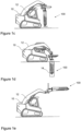
- Figures 1c to 1e illustrate the encased soil auger apparatus 100 connected to boom 12 of the skid-steer 10 with: Figure 1c illustrating the encased soil auger apparatus 100 in a raised vertical position prior drilling; Figure 1d illustrating the encased soil auger apparatus 100 fully disposed in drilled test pit 14; and Figure 1e illustrating the encased soil auger apparatus 100 a raised horizontal position for soil screening.
- the pivoting control arms 108 are, at a first end thereof, pivotally movable mounted to a commercially available auger quick mount plate 110 via, for example, steel mounting plates 122 welded to the auger quick mount plate 110 and gusseted mounting tabs 123 welded or otherwise fastened in a conventional manner to the respective steel mounting plate 122.
- a second end of each of the pivoting control arms 108 is pivotally movable mounted to the split end plate and mounting ring 104 in a conventional manner.
- FIG 3a illustrates a soil auger 102 according to an embodiment of the invention mounted to the quick mount plate 110 with separated auger casing 101 and separated end cap 119.
- the auger casing 101 is made, for example, as a frame structure comprising two rings 101A forming the two end portions of the auger casing 101 and connecting members 101B with the rings 101A and connecting members 101B made of, for example, sheet material and welded together in a conventional manner.
- Screen 101C for example, a steel wire mesh, is mounted to the frame structure in a conventional manner.
- the auger casing 101 is made of sheet material forming the wall thereof, for example, steel sheet material is rolled in cylindrical shape and welded in a conventional manner.
- Openings 106 are disposed in the sheet material in conventional manner using punching or laser cutting technology.
- the auger casing 101 has, preferably, a wall thickness between 3.18 mm and 19.1 mm (1/8" and 3 ⁇ 4") depending on the type of sediment in the test area.
- the mesh size or the size of the openings is determined in dependence upon the size of particles that are desired to be retained in the auger screen 101 after screening.
- the size is a standard size used in archaeological testing, for example 6.35 mm (1/4").
- auger casings 101 having different screen sizes, for example, 3.18 mm (1/8"), are provided, in order to enable changing of the screen size during testing, for example, depending if archaeological remains have been found or not.
- the second end of the auger casing 101 is mounted to the mounting ring 104 in a conventional manner using, for example, screw fasteners or a clamping mechanism, enabling simple mounting/removal of the same.
- End cap 119 is made in a similar fashion as the auger casing 101 as a frame structure with a wire mesh or made of sheet material having openings disposed therein. Optionally, the openings re omitted in the end cap 119.
- the end cap 119 further comprises a fastening mechanism such as, for example, chain binders or ratchet straps 120 to easily and removably attach the same to the auger casing 101.
- the end cap 119 is employed for enclosing the soil engaging end portion of the auger after extraction of the soil and during screening.
- Figure 3b illustrates the soil auger 102 having the auger casing 101 and the end cap 119 mounted thereto, as it is used after extraction of the soil and during screening.
- the soil engaging end portion 105 of the auger 102 extends from the longitudinal axis 150 approximately a same distance as an outside radius R of the auger casing 101, in order to provide clearance for the auger casing in the borehole.
- the soil engaging end portion 105 comprises a plurality of cutting teeth 105A with an outer cutting tooth 105A.1 extending from an outside edge 102A of the auger screw blade 102.
- the extracted soil contained in the auger casing 101 is then screened, for example, by rotating the soil auger 102 clockwise and counterclockwise in an alternating fashion. Smaller particles of the screened soil fall to the ground or are collected in a respective receptacle, as illustrated in Figures 5f and 5g , respectively.
- larger objects are collected in the end cap 119, for example, by moving the encased soil auger apparatus such that the longitudinal axis thereof is oriented substantially vertical and rotating the soil auger to transport the remaining larger objects into the end cap 119.
- the end cap 119 with the collected larger objects is then removed from the auger casing 101 and the encased soil auger apparatus 100 is ready for drilling the next test pit, as illustrated in Figure 5h .
- the collected larger objects are then investigated by an archaeologist to determine if the test pit is positive or negative for archaeological remains.
- water is injected into the auger casing 101 during screening, Figures 5f and 5g .
Landscapes
- Life Sciences & Earth Sciences (AREA)
- Engineering & Computer Science (AREA)
- Mining & Mineral Resources (AREA)
- Geology (AREA)
- General Life Sciences & Earth Sciences (AREA)
- Physics & Mathematics (AREA)
- Environmental & Geological Engineering (AREA)
- Chemical & Material Sciences (AREA)
- Geochemistry & Mineralogy (AREA)
- Fluid Mechanics (AREA)
- Analytical Chemistry (AREA)
- Soil Sciences (AREA)
- Health & Medical Sciences (AREA)
- Mechanical Engineering (AREA)
- Immunology (AREA)
- General Health & Medical Sciences (AREA)
- Pathology (AREA)
- General Physics & Mathematics (AREA)
- Biochemistry (AREA)
- Paleontology (AREA)
- Civil Engineering (AREA)
- Structural Engineering (AREA)
- General Engineering & Computer Science (AREA)
- Remote Sensing (AREA)
- Food Science & Technology (AREA)
- Medicinal Chemistry (AREA)
- Investigation Of Foundation Soil And Reinforcement Of Foundation Soil By Compacting Or Drainage (AREA)
- Earth Drilling (AREA)
Claims (12)
- Un appareil de tarière de sol encastré (100) destiné à l'extraction mécanique et au traitement de sol pour des évaluations archéologiques, comprenant :une coque de tarière (101) formant un corps cylindrique creux, une paroi de la coque de tarière ayant une pluralité d'ouvertures (106) ayant une taille prédéterminée pour permettre à des particules de les traverser ; etune tarière de sol (102) ayant une lame de vis hélicoïdale disposée dans la coque de tarière d'une manière coaxiale, une partie d'extrémité de mise en contact avec le sol (105) de la tarière saillant d'une première extrémité (101A) de la coque de tarière ;dans lequel la coque de tarière (101) comprend un crible (101C).
- L'appareil de tarière de sol encastré (100) selon la revendication 1, dans lequel la partie d'extrémité de mise en contact avec le sol (105) de la tarière (102) s'étend depuis un axe longitudinal de celui-ci (150) approximativement d'une distance identique à un rayon extérieur de la coque de tarière (101).
- L'appareil de tarière de sol encastré (100) selon la revendication 2, dans lequel la partie d'extrémité de mise en contact avec le sol (105) de la tarière (102) comprend une pluralité de dents de coupe (105A) avec une dent de coupe extérieure (105A.1) s'étendant depuis un bord extérieur (102A) de la lame de vis de la tarière.
- L'appareil de tarière de sol encastré (100) selon la revendication 1, comprenant en outre une extrémité plate (110) montée sur une deuxième extrémité (101B) de la coque de tarière (101).
- L'appareil de tarière de sol encastré (100) selon la revendication 1, comprenant en outre un capuchon d'extrémité (119) pour fermer la partie d'extrémité de mise en contact avec le sol (105) de la tarière (102) après l'extraction du sol.
- L'appareil de tarière de sol encastré (100) selon la revendication 5, dans lequel une paroi du capuchon d'extrémité (119) a une pluralité d'ouvertures ayant une taille prédéterminée pour permettre à des particules de les traverser.
- L'appareil de tarière de sol encastré (100) selon la revendication 1, comprenant en outre une entrée d'eau (115) pour injecter de l'eau dans la coque de tarière (101) par une deuxième extrémité de celui-ci.
- L'appareil de tarière de sol encastré (100) selon la revendication 1, dans lequel le crible (101C) est un treillis métallique en acier.
- Un procédé destiné à extraire et cribler un sol comprenant :la fourniture d'un appareil de tarière de sol encastré (100) selon la revendication 1 ;le placement de l'appareil de tarière de sol encastré à un emplacement prédéterminé avec un axe longitudinal (150) de celui-ci orienté sensiblement à la verticale ;le forage de l'appareil de tarière de sol encastré dans le sol jusqu'à ce qu'une profondeur prédéterminée soit atteinte ;le retrait de l'appareil de tarière de sol encastré contenant le sol extrait ;l'utilisation d'un capuchon d'extrémité (119) pour fermer la partie d'extrémité de mise en contact avec le sol (105) de la tarière (102) ;le déplacement de l'appareil de tarière de sol encastré de telle sorte que l'axe longitudinal de celui-ci est orienté sensiblement à l'horizontale ; etle criblage du sol extrait.
- Le procédé selon la revendication 9, dans lequel, pendant le criblage, la tarière de sol (102) est tournée dans le sens horaire et dans le sens antihoraire d'une manière alternée.
- Le procédé selon la revendication 9, comprenant en outre la collecte d'objets plus grands dans le capuchon d'extrémité (119) en déplaçant l'appareil de tarière de sol encastré (100) de telle sorte que l'axe longitudinal (150) de celui-ci est orienté sensiblement à la verticale.
- Le procédé selon la revendication 9, comprenant en outre l'injection d'eau dans la coque de tarière (101) pendant le criblage.
Applications Claiming Priority (2)
| Application Number | Priority Date | Filing Date | Title |
|---|---|---|---|
| CA2946944A CA2946944C (fr) | 2016-10-28 | 2016-10-28 | Appareillage de tariere integree destine a des evaluations archeologiques et methode d'utilisation associee |
| PCT/CA2017/000024 WO2018076095A1 (fr) | 2016-10-28 | 2017-02-03 | Appareil de tarière de sol encastré pour évaluations archéologiques et son procédé de fonctionnement |
Publications (4)
| Publication Number | Publication Date |
|---|---|
| EP3443193A1 EP3443193A1 (fr) | 2019-02-20 |
| EP3443193A4 EP3443193A4 (fr) | 2019-11-20 |
| EP3443193C0 EP3443193C0 (fr) | 2025-02-26 |
| EP3443193B1 true EP3443193B1 (fr) | 2025-02-26 |
Family
ID=62017669
Family Applications (1)
| Application Number | Title | Priority Date | Filing Date |
|---|---|---|---|
| EP17864759.0A Active EP3443193B1 (fr) | 2016-10-28 | 2017-02-03 | Appareil de tarière de sol encastré pour évaluations archéologiques et son procédé de fonctionnement |
Country Status (6)
| Country | Link |
|---|---|
| US (1) | US11125656B2 (fr) |
| EP (1) | EP3443193B1 (fr) |
| AU (1) | AU2017351759B2 (fr) |
| CA (1) | CA2946944C (fr) |
| GB (1) | GB2564989B (fr) |
| WO (1) | WO2018076095A1 (fr) |
Families Citing this family (20)
| Publication number | Priority date | Publication date | Assignee | Title |
|---|---|---|---|---|
| CA3052082A1 (fr) * | 2017-02-06 | 2018-08-09 | The University Of British Columbia | Appareil et procede de surveillance de perte de sol de couverture |
| US10781637B1 (en) * | 2018-11-05 | 2020-09-22 | Eric Lee Hall | In-ground container installation apparatuses and auger blade assemblies |
| JP6617326B1 (ja) * | 2018-11-27 | 2019-12-11 | 广州崢航机械設備有限公司 | 建築施工用の土層突っ込み装置 |
| JP6617328B1 (ja) * | 2018-11-27 | 2019-12-11 | 广州崢航机械設備有限公司 | 土層突っ込み装置 |
| JP6617327B1 (ja) * | 2018-11-27 | 2019-12-11 | 佛山単常科技有限公司 | 突っ込み設備 |
| USD910830S1 (en) * | 2019-04-12 | 2021-02-16 | Saint-Gobain Ceramics & Plastics, Inc. | Flame diffuser insert for immersion tube furnace |
| USD910829S1 (en) * | 2019-04-12 | 2021-02-16 | Saint-Gobain Ceramics & Plastics, Inc. | Flame diffuser insert for immersion tube furnace |
| CN110595821B (zh) * | 2019-09-30 | 2021-11-09 | 安徽金联地矿科技有限公司 | 用于表层沉积物的采集装置 |
| CN110542580A (zh) * | 2019-10-15 | 2019-12-06 | 贵州天保生态股份有限公司 | 一种水利水电工程用地基岩土试验检测取土装置及取土方法 |
| CN110687275B (zh) * | 2019-11-21 | 2022-01-11 | 邢台医学高等专科学校 | 一种用于土壤成分的检测设备及其检测方法 |
| CN110926860A (zh) * | 2019-12-12 | 2020-03-27 | 武钰华 | 一种岩土工程用岩土取样设备 |
| CN111982573B (zh) * | 2020-08-27 | 2021-06-15 | 青海九零六工程勘察设计院 | 一种水文地质钻式探测装置 |
| CN111911149B (zh) * | 2020-08-31 | 2021-08-24 | 中国科学院空间应用工程与技术中心 | 一种基于仿生技术的分离内杆式深层月壤钻进装置 |
| US11401748B2 (en) | 2020-12-10 | 2022-08-02 | Honeywell Federal Manufacturing & Technologies, Llc | Shrouded screw device for removing and depositing material |
| USD963704S1 (en) * | 2020-12-30 | 2022-09-13 | Dipperfox Oü | Drill bit |
| CN114112509B (zh) * | 2021-12-15 | 2022-06-07 | 南京工业大学 | 一种土动三轴试验土样装膜器 |
| CN114704199A (zh) * | 2022-03-31 | 2022-07-05 | 山东省地质矿产勘查开发局第七地质大队(山东省第七地质矿产勘查院) | 一种稀土矿勘探钻探取样装置 |
| CN116678667A (zh) * | 2023-06-15 | 2023-09-01 | 九江礼涞生物科技有限公司 | 一种农田重金属治理用检测装置及其使用方法 |
| CN118090295B (zh) * | 2024-02-26 | 2024-12-17 | 河南省地质局矿产资源勘查中心 | 一种便携式地质矿产勘查用取样装置 |
| CN118050205B (zh) * | 2024-04-16 | 2024-06-11 | 山东省国土空间生态修复中心(山东省地质灾害防治技术指导中心、山东省土地储备中心) | 一种地质遗迹现场的岩心提取器 |
Family Cites Families (12)
| Publication number | Priority date | Publication date | Assignee | Title |
|---|---|---|---|---|
| US2735703A (en) * | 1956-02-21 | goodman | ||
| JPS5038888B1 (fr) * | 1968-03-07 | 1975-12-12 | ||
| FR2408693A1 (fr) * | 1977-11-15 | 1979-06-08 | Causse Antoine | Outil de carottage a clapets pour le creusement de trous dans le sol |
| GB2133821B (en) * | 1983-01-19 | 1986-04-30 | Shuntaro Shiga | An obstacle-ground earth auger and in-line engineering method for excavating the obstacle ground |
| US4653336A (en) * | 1986-04-14 | 1987-03-31 | Vollweiler Arthur R | Combination soil auger and soil core sampler with sample retaining capacity |
| US5245878A (en) | 1991-07-12 | 1993-09-21 | Underwood John P | Vegetation maintenance system |
| US5476017A (en) * | 1993-10-15 | 1995-12-19 | Acutrol Co. | Unit dose bulk material sampling apparatus |
| EP1640507A1 (fr) | 2004-09-23 | 2006-03-29 | BAUER Maschinen GmbH | Appareil de forage pour pieu |
| EP1895090B1 (fr) | 2006-08-23 | 2008-10-15 | BAUER Maschinen GmbH | Procédé et dispositif de réalisation d'un trou de forage dans le sol |
| EP1905945A1 (fr) * | 2006-09-22 | 2008-04-02 | BAUER Maschinen GmbH | Tarière pour excaver un puits dans le sol |
| US8365638B2 (en) | 2009-03-31 | 2013-02-05 | Frank Paxton | Tubular soil auger and manufacturing method |
| KR20120109437A (ko) * | 2012-08-22 | 2012-10-08 | 최근규 | 시트파일용 가이드 롤러가 포함된 굴착장치 |
-
2016
- 2016-10-28 CA CA2946944A patent/CA2946944C/fr active Active
-
2017
- 2017-02-03 GB GB1817315.3A patent/GB2564989B/en active Active
- 2017-02-03 AU AU2017351759A patent/AU2017351759B2/en active Active
- 2017-02-03 US US16/345,417 patent/US11125656B2/en active Active
- 2017-02-03 WO PCT/CA2017/000024 patent/WO2018076095A1/fr not_active Ceased
- 2017-02-03 EP EP17864759.0A patent/EP3443193B1/fr active Active
Also Published As
| Publication number | Publication date |
|---|---|
| GB2564989B (en) | 2021-05-05 |
| US20190250072A1 (en) | 2019-08-15 |
| WO2018076095A1 (fr) | 2018-05-03 |
| EP3443193A4 (fr) | 2019-11-20 |
| EP3443193C0 (fr) | 2025-02-26 |
| GB201817315D0 (en) | 2018-12-05 |
| CA2946944C (fr) | 2022-03-22 |
| AU2017351759A1 (en) | 2018-10-25 |
| CA2946944A1 (fr) | 2018-04-28 |
| GB2564989A (en) | 2019-01-30 |
| EP3443193A1 (fr) | 2019-02-20 |
| US11125656B2 (en) | 2021-09-21 |
| AU2017351759B2 (en) | 2022-02-03 |
Similar Documents
| Publication | Publication Date | Title |
|---|---|---|
| EP3443193B1 (fr) | Appareil de tarière de sol encastré pour évaluations archéologiques et son procédé de fonctionnement | |
| CN107407131B (zh) | 用于钻探系统的竖井扩大布置 | |
| JP5274523B2 (ja) | 掘削機および掘削方法 | |
| DE3873407T2 (de) | Verfahren zum zementieren eines foerderrohres in einem unterirdischen gekruemmten bohrloch. | |
| JP6144542B2 (ja) | 中堀掘削機 | |
| JP2021169733A (ja) | 撹拌装置 | |
| KR101529700B1 (ko) | 시추장치 및 시추방법 | |
| CN112854239A (zh) | 一种超深淤泥质土层三轴搅拌桩加固施工方法 | |
| US9650833B2 (en) | Portable modular earth boring machine | |
| JP4344762B2 (ja) | 掘削方法および掘削装置 | |
| JP4811654B2 (ja) | オールケーシング工法における拡大根造成方法及び拡大掘削装置 | |
| KR100804751B1 (ko) | 자주식 지반 굴착기 및 그 굴착기를 이용한 굴착방법 | |
| JP2615096B2 (ja) | 掘孔方法 | |
| EP3938615B1 (fr) | Unité de concassage de roche pour élargir un trou pilote réalisé sur un terrain rocheux | |
| KR20170091274A (ko) | 지하수와 지열 굴착공의 케이싱 삽입 착정 장치 및 이를 이용한 굴착공 케이싱 삽입 착정 방법 | |
| US4102412A (en) | Apparatus and method for placing explosives in submerged rock | |
| JP3187326B2 (ja) | 縦穴掘削機 | |
| JP2005314871A (ja) | 地中障害物の除去装置、および地中障害物の除去方法 | |
| US12281454B2 (en) | Automatic pilot valve system for foundation tooling | |
| JP2001323784A (ja) | シールド掘進機の岩礫除去装置 | |
| JP2018178456A (ja) | 地中障害物除去方法 | |
| JPH11200763A (ja) | 地中掘削機 | |
| JP2000080877A (ja) | 掘削装置の汚濁防止・ズリ受け装置 | |
| KR101676028B1 (ko) | 고압유체 주입식 자동 슬라임 제거형 굴착 장치 및 이를 이용한 지중 굴착공 굴착과 슬라임 제거 방법 | |
| CN119083989A (zh) | 一种水利工程地质检测装置 |
Legal Events
| Date | Code | Title | Description |
|---|---|---|---|
| STAA | Information on the status of an ep patent application or granted ep patent |
Free format text: STATUS: THE INTERNATIONAL PUBLICATION HAS BEEN MADE |
|
| PUAI | Public reference made under article 153(3) epc to a published international application that has entered the european phase |
Free format text: ORIGINAL CODE: 0009012 |
|
| STAA | Information on the status of an ep patent application or granted ep patent |
Free format text: STATUS: REQUEST FOR EXAMINATION WAS MADE |
|
| 17P | Request for examination filed |
Effective date: 20181112 |
|
| AK | Designated contracting states |
Kind code of ref document: A1 Designated state(s): AL AT BE BG CH CY CZ DE DK EE ES FI FR GB GR HR HU IE IS IT LI LT LU LV MC MK MT NL NO PL PT RO RS SE SI SK SM TR |
|
| AX | Request for extension of the european patent |
Extension state: BA ME |
|
| A4 | Supplementary search report drawn up and despatched |
Effective date: 20191023 |
|
| RIC1 | Information provided on ipc code assigned before grant |
Ipc: E21B 7/20 20060101ALI20191017BHEP Ipc: E21B 49/02 20060101ALI20191017BHEP Ipc: E21B 10/44 20060101AFI20191017BHEP Ipc: E02D 1/04 20060101ALI20191017BHEP |
|
| DAV | Request for validation of the european patent (deleted) | ||
| DAX | Request for extension of the european patent (deleted) | ||
| STAA | Information on the status of an ep patent application or granted ep patent |
Free format text: STATUS: EXAMINATION IS IN PROGRESS |
|
| 17Q | First examination report despatched |
Effective date: 20200504 |
|
| GRAP | Despatch of communication of intention to grant a patent |
Free format text: ORIGINAL CODE: EPIDOSNIGR1 |
|
| STAA | Information on the status of an ep patent application or granted ep patent |
Free format text: STATUS: GRANT OF PATENT IS INTENDED |
|
| INTG | Intention to grant announced |
Effective date: 20240814 |
|
| GRAS | Grant fee paid |
Free format text: ORIGINAL CODE: EPIDOSNIGR3 |
|
| RBV | Designated contracting states (corrected) |
Designated state(s): AL AT BE BG CH CY CZ DE DK EE ES FI FR GR HR HU IE IS IT LI LT LU LV MC MK MT NL NO PL PT RO RS SE SI SK SM TR |
|
| GRAA | (expected) grant |
Free format text: ORIGINAL CODE: 0009210 |
|
| STAA | Information on the status of an ep patent application or granted ep patent |
Free format text: STATUS: THE PATENT HAS BEEN GRANTED |
|
| AK | Designated contracting states |
Kind code of ref document: B1 Designated state(s): AL AT BE BG CH CY CZ DE DK EE ES FI FR GR HR HU IE IS IT LI LT LU LV MC MK MT NL NO PL PT RO RS SE SI SK SM TR |
|
| REG | Reference to a national code |
Ref country code: CH Ref legal event code: EP |
|
| REG | Reference to a national code |
Ref country code: DE Ref legal event code: R096 Ref document number: 602017088052 Country of ref document: DE |
|
| REG | Reference to a national code |
Ref country code: IE Ref legal event code: FG4D |
|
| U01 | Request for unitary effect filed |
Effective date: 20250324 |
|
| U07 | Unitary effect registered |
Designated state(s): AT BE BG DE DK EE FI FR IT LT LU LV MT NL PT RO SE SI Effective date: 20250328 |
|
| PG25 | Lapsed in a contracting state [announced via postgrant information from national office to epo] |
Ref country code: RS Free format text: LAPSE BECAUSE OF FAILURE TO SUBMIT A TRANSLATION OF THE DESCRIPTION OR TO PAY THE FEE WITHIN THE PRESCRIBED TIME-LIMIT Effective date: 20250526 |
|
| PG25 | Lapsed in a contracting state [announced via postgrant information from national office to epo] |
Ref country code: PL Free format text: LAPSE BECAUSE OF FAILURE TO SUBMIT A TRANSLATION OF THE DESCRIPTION OR TO PAY THE FEE WITHIN THE PRESCRIBED TIME-LIMIT Effective date: 20250226 |
|
| PG25 | Lapsed in a contracting state [announced via postgrant information from national office to epo] |
Ref country code: ES Free format text: LAPSE BECAUSE OF FAILURE TO SUBMIT A TRANSLATION OF THE DESCRIPTION OR TO PAY THE FEE WITHIN THE PRESCRIBED TIME-LIMIT Effective date: 20250226 |
|
| PG25 | Lapsed in a contracting state [announced via postgrant information from national office to epo] |
Ref country code: NO Free format text: LAPSE BECAUSE OF FAILURE TO SUBMIT A TRANSLATION OF THE DESCRIPTION OR TO PAY THE FEE WITHIN THE PRESCRIBED TIME-LIMIT Effective date: 20250526 Ref country code: IS Free format text: LAPSE BECAUSE OF FAILURE TO SUBMIT A TRANSLATION OF THE DESCRIPTION OR TO PAY THE FEE WITHIN THE PRESCRIBED TIME-LIMIT Effective date: 20250626 |
|
| PG25 | Lapsed in a contracting state [announced via postgrant information from national office to epo] |
Ref country code: HR Free format text: LAPSE BECAUSE OF FAILURE TO SUBMIT A TRANSLATION OF THE DESCRIPTION OR TO PAY THE FEE WITHIN THE PRESCRIBED TIME-LIMIT Effective date: 20250226 |
|
| PG25 | Lapsed in a contracting state [announced via postgrant information from national office to epo] |
Ref country code: GR Free format text: LAPSE BECAUSE OF FAILURE TO SUBMIT A TRANSLATION OF THE DESCRIPTION OR TO PAY THE FEE WITHIN THE PRESCRIBED TIME-LIMIT Effective date: 20250527 |
|
| PG25 | Lapsed in a contracting state [announced via postgrant information from national office to epo] |
Ref country code: SM Free format text: LAPSE BECAUSE OF FAILURE TO SUBMIT A TRANSLATION OF THE DESCRIPTION OR TO PAY THE FEE WITHIN THE PRESCRIBED TIME-LIMIT Effective date: 20250226 |
|
| PG25 | Lapsed in a contracting state [announced via postgrant information from national office to epo] |
Ref country code: CZ Free format text: LAPSE BECAUSE OF FAILURE TO SUBMIT A TRANSLATION OF THE DESCRIPTION OR TO PAY THE FEE WITHIN THE PRESCRIBED TIME-LIMIT Effective date: 20250226 |
|
| PG25 | Lapsed in a contracting state [announced via postgrant information from national office to epo] |
Ref country code: SK Free format text: LAPSE BECAUSE OF FAILURE TO SUBMIT A TRANSLATION OF THE DESCRIPTION OR TO PAY THE FEE WITHIN THE PRESCRIBED TIME-LIMIT Effective date: 20250226 |
|
| PLBE | No opposition filed within time limit |
Free format text: ORIGINAL CODE: 0009261 |
|
| STAA | Information on the status of an ep patent application or granted ep patent |
Free format text: STATUS: NO OPPOSITION FILED WITHIN TIME LIMIT |
|
| 26N | No opposition filed |
Effective date: 20251127 |
|
| U20 | Renewal fee for the european patent with unitary effect paid |
Year of fee payment: 10 Effective date: 20260120 |