EP3443220B1 - Windturbine mit mehreren rotoren - Google Patents
Windturbine mit mehreren rotoren Download PDFInfo
- Publication number
- EP3443220B1 EP3443220B1 EP17717072.7A EP17717072A EP3443220B1 EP 3443220 B1 EP3443220 B1 EP 3443220B1 EP 17717072 A EP17717072 A EP 17717072A EP 3443220 B1 EP3443220 B1 EP 3443220B1
- Authority
- EP
- European Patent Office
- Prior art keywords
- energy generating
- generating units
- wind turbine
- gravity
- rotors
- Prior art date
- Legal status (The legal status is an assumption and is not a legal conclusion. Google has not performed a legal analysis and makes no representation as to the accuracy of the status listed.)
- Active
Links
Images







Classifications
-
- F—MECHANICAL ENGINEERING; LIGHTING; HEATING; WEAPONS; BLASTING
- F03—MACHINES OR ENGINES FOR LIQUIDS; WIND, SPRING, OR WEIGHT MOTORS; PRODUCING MECHANICAL POWER OR A REACTIVE PROPULSIVE THRUST, NOT OTHERWISE PROVIDED FOR
- F03D—WIND MOTORS
- F03D1/00—Wind motors with rotation axis substantially parallel to the air flow entering the rotor
- F03D1/02—Wind motors with rotation axis substantially parallel to the air flow entering the rotor having a plurality of rotors
-
- F—MECHANICAL ENGINEERING; LIGHTING; HEATING; WEAPONS; BLASTING
- F03—MACHINES OR ENGINES FOR LIQUIDS; WIND, SPRING, OR WEIGHT MOTORS; PRODUCING MECHANICAL POWER OR A REACTIVE PROPULSIVE THRUST, NOT OTHERWISE PROVIDED FOR
- F03D—WIND MOTORS
- F03D13/00—Assembly, mounting or commissioning of wind motors; Arrangements specially adapted for transporting wind motor components
- F03D13/20—Arrangements for mounting or supporting wind motors; Masts or towers for wind motors
-
- F—MECHANICAL ENGINEERING; LIGHTING; HEATING; WEAPONS; BLASTING
- F03—MACHINES OR ENGINES FOR LIQUIDS; WIND, SPRING, OR WEIGHT MOTORS; PRODUCING MECHANICAL POWER OR A REACTIVE PROPULSIVE THRUST, NOT OTHERWISE PROVIDED FOR
- F03D—WIND MOTORS
- F03D7/00—Controlling wind motors
- F03D7/02—Controlling wind motors the wind motors having rotation axis substantially parallel to the air flow entering the rotor
- F03D7/0204—Controlling wind motors the wind motors having rotation axis substantially parallel to the air flow entering the rotor for orientation in relation to wind direction
-
- F—MECHANICAL ENGINEERING; LIGHTING; HEATING; WEAPONS; BLASTING
- F05—INDEXING SCHEMES RELATING TO ENGINES OR PUMPS IN VARIOUS SUBCLASSES OF CLASSES F01-F04
- F05B—INDEXING SCHEME RELATING TO WIND, SPRING, WEIGHT, INERTIA OR LIKE MOTORS, TO MACHINES OR ENGINES FOR LIQUIDS COVERED BY SUBCLASSES F03B, F03D AND F03G
- F05B2240/00—Components
- F05B2240/20—Rotors
- F05B2240/21—Rotors for wind turbines
- F05B2240/221—Rotors for wind turbines with horizontal axis
- F05B2240/2211—Rotors for wind turbines with horizontal axis of the multibladed, low speed, e.g. "American farm" type
-
- F—MECHANICAL ENGINEERING; LIGHTING; HEATING; WEAPONS; BLASTING
- F05—INDEXING SCHEMES RELATING TO ENGINES OR PUMPS IN VARIOUS SUBCLASSES OF CLASSES F01-F04
- F05B—INDEXING SCHEME RELATING TO WIND, SPRING, WEIGHT, INERTIA OR LIKE MOTORS, TO MACHINES OR ENGINES FOR LIQUIDS COVERED BY SUBCLASSES F03B, F03D AND F03G
- F05B2240/00—Components
- F05B2240/20—Rotors
- F05B2240/21—Rotors for wind turbines
- F05B2240/221—Rotors for wind turbines with horizontal axis
- F05B2240/2213—Rotors for wind turbines with horizontal axis and with the rotor downwind from the yaw pivot axis
-
- F—MECHANICAL ENGINEERING; LIGHTING; HEATING; WEAPONS; BLASTING
- F05—INDEXING SCHEMES RELATING TO ENGINES OR PUMPS IN VARIOUS SUBCLASSES OF CLASSES F01-F04
- F05B—INDEXING SCHEME RELATING TO WIND, SPRING, WEIGHT, INERTIA OR LIKE MOTORS, TO MACHINES OR ENGINES FOR LIQUIDS COVERED BY SUBCLASSES F03B, F03D AND F03G
- F05B2270/00—Control
- F05B2270/40—Type of control system
- F05B2270/402—Type of control system passive or reactive, e.g. using large wind vanes
-
- Y—GENERAL TAGGING OF NEW TECHNOLOGICAL DEVELOPMENTS; GENERAL TAGGING OF CROSS-SECTIONAL TECHNOLOGIES SPANNING OVER SEVERAL SECTIONS OF THE IPC; TECHNICAL SUBJECTS COVERED BY FORMER USPC CROSS-REFERENCE ART COLLECTIONS [XRACs] AND DIGESTS
- Y02—TECHNOLOGIES OR APPLICATIONS FOR MITIGATION OR ADAPTATION AGAINST CLIMATE CHANGE
- Y02E—REDUCTION OF GREENHOUSE GAS [GHG] EMISSIONS, RELATED TO ENERGY GENERATION, TRANSMISSION OR DISTRIBUTION
- Y02E10/00—Energy generation through renewable energy sources
- Y02E10/70—Wind energy
- Y02E10/72—Wind turbines with rotation axis in wind direction
-
- Y—GENERAL TAGGING OF NEW TECHNOLOGICAL DEVELOPMENTS; GENERAL TAGGING OF CROSS-SECTIONAL TECHNOLOGIES SPANNING OVER SEVERAL SECTIONS OF THE IPC; TECHNICAL SUBJECTS COVERED BY FORMER USPC CROSS-REFERENCE ART COLLECTIONS [XRACs] AND DIGESTS
- Y02—TECHNOLOGIES OR APPLICATIONS FOR MITIGATION OR ADAPTATION AGAINST CLIMATE CHANGE
- Y02E—REDUCTION OF GREENHOUSE GAS [GHG] EMISSIONS, RELATED TO ENERGY GENERATION, TRANSMISSION OR DISTRIBUTION
- Y02E10/00—Energy generation through renewable energy sources
- Y02E10/70—Wind energy
- Y02E10/728—Onshore wind turbines
Definitions
- the present invention relates to a multirotor wind turbine, i.e. a wind turbine comprising two or more energy generating units arranged on a common tower structure, each energy generating unit comprising a rotor.
- the multirotor wind turbine according to the invention is capable of reliable self-yawing, even under turbulent wind conditions. Furthermore, according to some of the embodiments of the invention, the multirotor wind turbine provides torque equalization.
- Wind turbines normally comprise one or more energy generating units, each energy generating unit comprising a rotor comprising a hub carrying one or more wind turbine blades.
- the wind acts on the wind turbine blades, thereby causing the hub to rotate.
- the rotational movements of the hub are transferred to a generator, either via a gear arrangement or directly, in the case that the wind turbine is of a so-called direct drive type.
- electrical energy is generated, which may be supplied to a power grid.
- Some wind turbines are provided with two or more energy generating units in order to increase the total power produced by the wind turbine, without having to provide the wind turbine with one very large, and therefore heavy, energy generating unit.
- Such wind turbines are sometimes referred to as 'multirotor wind turbines'.
- the energy generating units may be carried by a load carrying structure which is, in turn, connected to a tower structure. Thereby at least some of the energy generating units are not mounted directly on the tower structure, and they may have a centre of gravity which is displaced with respect to a longitudinal axis defined by the tower structure.
- thrust forces will be created, which will in turn cause loads to be introduced in the load carrying structure, and possibly at connection points between the load carrying structure and the tower structure.
- the load carrying structure(s) may be mounted on the tower structure in a rotatable manner via a yawing arrangement.
- the load carrying structure can perform yawing movements relative to the tower structure, thereby ensuring that the rotors are orientated in a correct manner with respect to the incoming wind.
- the yawing movements may be performed actively, e.g. by means of one or more yawing motors.
- the yawing system may be of a self-yawing kind which automatically ensures that the rotors are orientated correctly. This may, e.g., be obtained by providing the load carrying structure with a wind vane or the like.
- Prior art self-yawing mechanisms are known to operate reliably most of the time. However, under certain conditions, e.g. under turbulent wind conditions, there is a risk that these self-yawing mechanisms suddenly 'flip', i.e. rotate the entire load carrying structure approximately 180°, and the load carrying structure is subsequently slowly rotated into a correct orientation. This introduces undesirable loads on the wind turbine, and the energy production of the wind turbine is reduced while the load carrying structure is rotated into the correct orientation.
- EP 2 463 513 A1 discloses a wind power generating device comprising a tower column, a first wind generating set and a second wind generating set.
- the first wind generating set is installed at a position on the tower column near the top, and generates a first torque on the tower column during rotation for power generation.
- the second wind generating set is installed at a position on the tower column below the top, and generates a second torque on the tower column which at least partially counteracts the first torque.
- JP 2006-322383 discloses a wind power generating device comprising two upwind rotors and a stabilizing fin.
- the stabilizing fin ensures that the wind generating device is self-yawing.
- Examples of multi-rotor wind turbines are further known from GB 2 443 886 A GB2443886A , US20130127173 and FR 2 868 483 .
- the invention provides a multirotor wind turbine comprising a tower structure and at least one load carrying structure, each load carrying structure being arranged for carrying two or more first energy generating units and for being connected to the tower structure, each first energy generating unit comprising a first rotor, and each energy generating unit having a centre of gravity, wherein at least two of the rotors are downwind rotors, the first energy generating units comprising the at least two first downwind rotors being arranged with their respective centres of gravity at a first distance behind the tower structure along a direction of the incoming wind, substantially at the same vertical level, and at opposite sides of the tower structure at substantially the same second distance to the tower structure along a direction substantially perpendicular to the direction of the incoming wind.
- At least two of the rotors are downwind rotors, the energy generating units comprising downwind rotors being arranged with their centres of gravity at a first distance behind the tower structure along a direction of the incoming wind, substantially at the same vertical level, and at opposite sides of the tower structure at substantially the same second distance to the tower structure along a direction substantially perpendicular to the direction of the incoming wind.
- at least two of the first rotors are upwind rotors, the centres of gravity of which are arranged at the first distance in front of the tower structure along the direction of the incoming wind.
- Each rotor preferably comprises three blades.
- Each rotor may preferably constitute a horizontal-axis rotor.
- the rotors may be driven at the same RPM, or at different RPM. They may be of the same diameter or different diameters. Choices of RPM and diameter may be made to avoid undesired vibrations, in particular with a view to avoiding resonances.
- the present invention relates to a multirotor wind turbine.
- the term 'multirotor wind turbine' should be interpreted to mean a wind turbine which comprises two or more energy generating units, each energy generating unit comprising a rotor.
- the wind turbine comprises a tower structure and at least one load carrying structure.
- the tower structure is preferably a substantially vertical structure which is anchored, at a lower part, to a foundation structure. Accordingly, the tower structure resembles a traditional wind turbine tower for a single rotor wind turbine.
- Each load carrying structure is arranged for carrying two or more energy generating units and for being connected to the tower structure. Accordingly, a given load carrying structure forms a connection between the two or more energy generating units, carried by the load carrying structure, and the tower structure, and is capable of handling the loads involved with carrying the energy generating units.
- Each energy generating unit thereby typically comprises a rotor, carrying a set of wind turbine blades, and a generator.
- the energy generating unit may further comprise a gear arrangement interconnecting the rotor and the generator.
- the generator, and possibly the gear arrangement, may be arranged inside a nacelle.
- Each energy generating unit has a centre of gravity.
- At least two of the rotors are downwind rotors.
- the term 'downwind rotor' should be interpreted to mean a rotor which, during normal operation, is arranged to be positioned at a leeward side of the tower structure.
- the downwind rotors are arranged behind the tower structure along the direction of the incoming wind.
- the at least two energy generating units which comprise downwind rotors are arranged with their centres of gravity at a first distance behind the tower structure along the direction of the incoming wind.
- the centres of gravity of the energy generating units comprising the downwind rotors are arranged behind the tower structure along the direction of the incoming wind, i.e. at the leeward side of the tower structure.
- the centres of gravity of the at least two energy generating units are arranged at a first distance behind the tower structure, i.e. they are arranged at the same distance from the tower structure. In other words, they are arranged in a plane behind the tower structure, the plane extending substantially perpendicularly to the direction of the incoming wind.
- centres of gravity of the two or more energy generating units comprising downwind rotors are arranged substantially at the same vertical level, i.e. substantially at the same height above the ground, or above the sea level in the case that the wind turbine is an offshore wind turbine.
- centres of gravity of the two or more energy generating units comprising downwind rotors are arranged at opposite sides of the tower structure at substantially the same second distance to the tower structure along a direction being substantially perpendicular to the direction of the incoming wind.
- a part of the wind turbine for instance the load carrying structure, is normally rotated about a rotational axis which coincides with a longitudinal direction defined by the tower structure. Accordingly, arranging the centres of gravity of the two or more energy generating units at the first distance behind the tower structure as described above, ensures that the centres of gravity are behind the rotation axis of the yawing movements, along the direction of the incoming wind. Accordingly, the point of attack of thrust forces acting on these energy generating units are also arranged behind the axis of rotation of the yawing movements, along the direction of the incoming wind.
- the wind turbine to be self-yawing, i.e. the wind turbine is automatically moved to a correct yaw position with respect to the incoming wind. Furthermore, the self-yawing is stable and reliable, even under turbulent wind conditions, since this arrangement of the energy generating units prevents that the yawing mechanism suddenly 'flips' in the manner described above.
- Arranging the centres of gravity of the energy generating units comprising downwind rotors substantially at the same vertical level and at opposite sides of the tower structure at substantially the same second distance to the tower structure along the direction substantially perpendicular to the direction of the incoming wind, ensures that the loads on the load carrying structure originating from gravity acting on the energy generating units are balanced. This even further stabilizes the self-yawing mechanism.
- a self-yawing multirotor wind turbine construction is interesting because it eliminates the cost of an active yaw mechanism and allows for a smaller tower diameter than would be required if a traditional, active yawing mechanism was applied.
- At least one of the at least one load carrying structure may be arranged to carry at least one second energy generating unit, the at least one second energy generating unit being in that case an upwind rotor the centre of gravity of at least one of the second energy generating units being arranged at a third distance from the tower structure along the direction of the incoming wind.
- the centre of gravity of at least one of the second energy generating units may be arranged at a vertical level which differs from the vertical level of at least one of the at least two first energy generating unit.
- the one or more second energy generating units may generally comprise downwind rotors, having their centres of gravity arranged in a different manner with respect to the tower structure than what is described above, as long as at least two of the energy generating units are arranged as described above.
- additional energy generating units could be arranged with their centres of gravity at a different vertical level and/or with a different distance to the tower structure along the direction of the incoming wind and/or along the direction substantially perpendicular to the incoming wind.
- At least one load carrying structure may be arranged to carry at least one further energy generating unit, at least one of the further energy generating units comprising an upwind rotor and the centre of gravity of the energy generating unit being arranged at a third distance in front of the tower structure along the direction of the incoming wind.
- the wind turbine comprises at least two energy generating units comprising downwind rotors and at least one energy generating unit comprising an upwind rotor.
- the wind turbine comprises at least two energy generating units comprising upwind rotors and at least one energy generating unit comprising a downwind rotor.
- the term 'upwind rotor' should be interpreted to mean a rotor which, during normal operation, is arranged to be positioned at an upwind side of the tower structure.
- the at least one or least two energy generating unit(s) comprising downwind rotor(s) is/are arranged with their centres of gravity behind the tower structure, along the direction of the incoming wind
- the at least one energy generating unit comprising an upwind rotor is/are arranged with its/their centre(s) of gravity in front of the tower structure, along the direction of the incoming wind
- the first distance and the third distance may be selected in an appropriate manner.
- the third distance may advantageously be approximately twice the first distance.
- the third distance may advantageously be approximately equal to the first distance.
- the one or more energy generating units comprising upwind rotors may be arranged in such a manner that the one or more energy generating units comprising downwind rotors are not arranged in its/their wake.
- the energy generating unit(s) comprising upwind rotor(s) may be arranged directly in front of the tower structure.
- the centre of gravity of the energy generating unit(s) comprising at least one upwind rotor may be arranged at a vertical level which differs from the vertical level of the at least one or at least two energy generating units comprising downwind rotors. Thereby it is ensured that the energy generating units comprising downwind rotors are arranged out of the wake of the energy generating unit comprising an upwind rotor.
- At least one load carrying structure may be arranged to carry at least two second energy generating units, the at least two second energy generating units carrying upwind rotors if said at least two first rotors are downwind rotors, and the at least two second energy generating units carrying downwind rotors if said at least two first rotors are upwind rotors, the at least two second energy generating units being arranged with their centres of gravity in a common vertical plane extending substantially perpendicularly to the direction of the incoming wind, at the third distance from the tower structure along the direction of the incoming wind.
- At least one load carrying structure may be arranged to carry at least two further energy generating units comprising upwind rotors, the at least two further energy generating units being arranged with their centres of gravity in a common vertical plane extending substantially perpendicularly to the direction of the incoming wind, at the third distance in front of the tower structure along the direction of the incoming wind.
- At least one of the load carrying structures carries at least two energy generating units comprising downwind rotors and at least two energy generating units comprising upwind rotors.
- the energy generating units comprising downwind rotors are preferably arranged with their centres of gravity behind the tower structure, in a common horizontal plane, and the energy generating units comprising upwind rotors are arranged with their centres of gravity in front of the tower structure, in a common vertical plane.
- the energy generating units comprising upwind rotors may be arranged, one above the other, in front of the tower structure.
- the energy generating units comprising upwind rotors may be arranged directly in front of the tower structure, as described above.
- At least one first and/or second energy generating unit comprising an upwind rotor may be arranged with its centre of gravity above the vertical level of at least one first and/or second energy generating unit comprising a downwind rotor, and at least one first and/or second energy generating unit comprising an upwind rotor is arranged with its centre of gravity below the vertical level of at least one first and/or second energy generating unit comprising a downwind rotor.
- At least one energy generating unit comprising an upwind rotor may be arranged with its centre of gravity above the vertical level of the energy generating units comprising downwind rotors, and at least one energy generating unit comprising an upwind rotor may be arranged with its centre of gravity below the vertical level of the energy generating units comprising downwind rotors.
- the torque introduced in the load carrying structure, due to the rotation of the rotors, is also balanced.
- the positions of the centres of gravity for two first and/or second energy generating units comprising downwind rotors and two first and/or second energy generating units comprising upwind rotors may form corners of a regular tetrahedron.
- the positions of the centres of gravity for two energy generating units comprising downwind rotors and two energy generating units comprising upwind rotors may form corners of a regular tetrahedron.
- At least one load carrying structure may arranged to carry at least three first and/or second energy generating units comprising a downwind rotor and at least two first and/or second energy generating units comprising an upwind rotor.
- the load carrying structure may comprise at least three arms, each arm carrying a first and/or second energy generating unit comprising a downwind rotor and a first and/or second energy generating unit comprising an upwind rotor, and each arm being connected to the tower structure via a common connecting part.
- At least one load carrying structure may be arranged to carry at least three energy generating units comprising a downwind rotor and at least three energy generating units comprising an upwind rotor, and the load carrying structure may comprise at least three arms, each arm carrying an energy generating unit comprising a downwind rotor and an energy generating unit comprising an upwind rotor, and each arm being connected to the tower structure via a common connecting part.
- each of the arms of the load carrying structure carries two energy generating units, i.e. one energy generating unit comprising a downwind rotor and one energy generating unit comprising an upwind rotor.
- the torque introduced in a given arm due to rotation of the rotors of the energy generating units, will balance at a position along the length of the arm which is approximately half way between the attachment points of the two energy generating units.
- the torque introduced in the arm due to gravity acting on the energy generating units will also balance at this position. Accordingly, if the arms are connected to the common connecting part at this position along the lengths of the arms, the torque transfer from the arms to the tower structure is minimised. Accordingly, the loads introduced in the common connecting part as well as in the tower structure are minimised.
- At least one load carrying structure may comprise at least two primary structures and at least two secondary structures, and gravity acting on the energy generating units being carried by the load carrying structure may cause push in the primary structures and pull in the secondary structures.
- the secondary structures are automatically preloaded, due to gravity acting on the energy generating units.
- the preloading of the secondary structures ensures that these structures are capable of handling loads originating from thrust of the energy generating units.
- thrust loads acting in one direction will increase the pull in a first secondary structure and decrease the pull in the second secondary structure
- thrust loads acting in an opposite direction will decrease the pull in the first secondary structure and increase the pull in the second secondary structure.
- the preload in the secondary structures ensures that a certain pull remains in each of the secondary structures, also when the pull is decreased, due to the thrust loads.
- the two opposing directions could, e.g., be the direction of the incoming wind and the opposite direction.
- the primary structures may be in the form of one or more compression bars.
- Compression bars are suitable for receiving push.
- the compression bars could, e.g., be in the form of tubes, rods, beams, such as I-beams, etc.
- the secondary structures may be in the form of one or more tension members.
- Tension members are suitable for receiving pull.
- the tension members could, e.g., be in the form bars or carbon fibre structures, or in the form of flexible members, such as wires, ropes, etc.
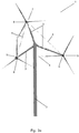
- Fig. 1 is a perspective view of a multirotor wind turbine 1 according to a first embodiment of the invention.
- the multirotor wind turbine 1 comprises a tower structure 2 and a load carrying structure in the form of two arms 3 extending away from the tower structure 2, and a wire 4.
- Each of the arms 3 carries an energy generating unit 5, and the wire 4 interconnects the energy generating units 5 or the parts of the arms 3 which carry the energy generating units 5.
- the entire load carrying structure 3, 4 is arranged to perform yawing movements with respect to the tower structure 2 about an axis of rotation which is substantially coinciding with a longitudinal axis defined by the tower structure 2, via a yawing mechanism (not shown).
- the energy generating units 5 can be orientated in a correct manner with respect to the incoming wind.
- Each energy generating unit 5 comprises a downwind rotor 6, and each energy generating unit 5 has a centre of gravity.
- the centres of gravity for both of the energy generating units 5 are arranged at a first distance behind the tower structure 2, along the direction of the incoming wind, i.e. at the leeward side of the tower structure 2. Accordingly, the points of attack of thrust forces acting on the energy generating units 5 are arranged behind the tower structure 2, and thereby behind the axis of rotation for the yawing movements of the load carrying structure 3, 4.
- the centres of gravity of the energy generating units 5 are arranged substantially at the same vertical level, and at opposite sides of the tower structure 2, at a second distance from the tower structure 2, along a direction substantially perpendicular to the incoming wind. Accordingly, the distances from each of the energy generating units 5 to the tower structure 2, along the direction perpendicular to the direction of the incoming wind, are substantially identical.
- the mutual positions of the energy generating units 5 and the tower structure 2 ensure that the load carrying structure 3, 4 is capable of performing self-yawing movements relative to the tower structure 2, in a stable and reliable manner, even under turbulent wind conditions.
- the arms 3 are relatively stiff, while the wire 4 is relatively flexible. Accordingly, gravity acting on the energy generating units 5 causes push in the arms 3 and pull in the wire 4.
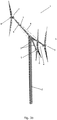
- Figs. 2a and 2b are perspective views of a multirotor wind turbine 1 according to a second embodiment of the invention, seen from two different angles.
- the multirotor wind turbine 1 of Figs. 2a and 2b is similar to the multirotor wind turbine 1 of Fig. 1 in that it comprises a tower structure 2 and a load carrying structure 3, 4, carrying two energy generating units 5, each comprising a downwind rotor 6. Furthermore, the mutual positions of the energy generating units 5 and the tower structure 2 are essentially as described above with reference to Fig. 1 .
- the load carrying structure comprises three arms 3 and three wires 4. Two of the arms 3 carry energy generating units 5 comprising downwind rotors 6, as described above with reference to Fig. 1 . Accordingly, the load carrying structure 3, 4 is also in this case capable of performing self-yawing in a reliable and stable manner, even under turbulent wind conditions.
- the third arm 3 carries a further energy generating unit 7 comprising an upwind rotor 8.
- the three wires 4 each interconnects two of the energy generating units 5, 7.
- the centre of gravity of the further energy generating unit 7 is arranged at a third distance in front of the tower structure 2 along the direction of the incoming wind. Furthermore, the centre of gravity of the further energy generating unit 7 is arranged at a lower vertical level than the centres of gravity of the two energy generating units 5 comprising downwind rotors 6.
- the third distance is substantially twice the first distance. Accordingly, the torque introduced in the load carrying structure 3, 4, due to gravity acting on the energy generating units 5, 7, is balanced at the point where the arms 3 are connected to the tower structure 2.
- the centre of gravity of the energy generating unit 7 comprising an upwind rotor 8 is arranged at a different vertical level than the centres of gravity of the energy generating units 5 comprising downwind rotors 6, it is ensured that the downwind rotors 6 are arranged substantially out of the wake of the upwind rotor 8. Accordingly, the total energy production of the multirotor wind turbine 1 is maximised.
- Figs. 3a and 3b are perspective views of a multirotor wind turbine 1 according to a third embodiment of the invention, seen from two different angles.
- the multirotor wind turbine 1 of Figs. 3a and 3b is very similar to the multirotor wind turbine 1 of Figs. 2a and 2b , and it will therefore not be described in further detail here.
- the centre of gravity of the energy generating unit 7 comprising an upwind rotor 8 is arranged at a higher vertical level than the centres of gravity of the energy generating units 5 comprising downwind rotors 6.
- the remarks set forth above with reference to Figs. 2a and 2b are equally applicable here.
- Figs. 4a and 4b are perspective views of a multirotor wind turbine 1 according to a fourth embodiment of the invention, seen from two different angles.
- the multirotor wind turbine 1 of Figs. 4a and 4b comprises a tower structure 2 and a load carrying structure 3, 4 carrying two energy generating units 5, each comprising a downwind rotor 6.
- the mutual positions of the energy generating units 5 comprising downwind rotors 6 and the tower structure 2 are essentially as described above with reference to Fig. 1 .
- the load carrying structure 3, 4 is, also in this case, capable of performing self-yawing movements with respect to the tower structure 2, in a stable and reliable manner, even under turbulent wind conditions.
- the load carrying structure of the multirotor wind turbine 1 of Figs. 4a and 4b comprises four arms 3 and six wires 4. Two of the arms 3 carry the energy generating units 5 comprising downwind rotors 6. The other two arms 3 each carry an energy generating unit 7 comprising an upwind rotor 8. The wires 4 interconnect each of the energy generating units 5, 7 to the other three energy generating units 5, 7.
- the centres of gravity of the energy generating units 7 comprising upwind rotors 8 are arranged, one above the other, in a common vertical plane.
- One of the energy generating units 7 is arranged above the vertical level of the energy generating units 5 comprising downwind rotors 6, and the other energy generating unit 7 is arranged below this vertical level.
- the first distance i.e. the distance from the tower structure 2 to the centres of gravity of the energy generating units 5 comprising downwind rotors 6, along the direction of the incoming wind
- the third distance i.e. the distance from the tower structure 2 to the centres of gravity of the energy generating units 7 comprising upwind rotors 8, along the direction of the incoming wind.
- the multirotor wind turbine 1 comprises two downwind rotors 6 and two upwind rotors 8, the torque introduced in the load carrying structure 3, 4, due to the rotation of the rotors 6, 8, is balanced at the position where the arms 3 are connected to the tower structure 2. Accordingly, the loads transferred from the arms 3 to the tower structure 2 are minimised.
- the four energy generating units 5, 7 are positioned in such a manner that the positions of their centres of gravity form the corners of a regular tetrahedron. This is a very stable construction, which ensures that torque introduced in the load carrying structure 3, 4, due to gravity acting on the energy generating units 5, 7 as well as due to rotation of the rotors 6, 8, is balanced.
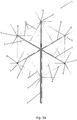
- FIGs. 5a and 5b are perspective views of a multirotor wind turbine 1 according to a fifth embodiment of the invention, seen from two different angles.
- the multirotor wind turbine 1 comprises a tower structure 2 and a load carrying structure comprising three arms 3 and a number of wires 4.
- Each of the arms 3 carries an energy generating unit 5 comprising a downwind rotor 6 and an energy generating unit 7 comprising an upwind rotor 8. Accordingly, the multirotor wind turbine 1 comprises three energy generating units 5 comprising downwind rotors 6 and three energy generating units 7 comprising upwind rotors 8.
- the arms 3 are connected to the tower structure 2 at a common point of connection.
- the centres of gravity of all of the energy generating units 5 comprising downwind rotors 6 are arranged in a common vertical plane, at a first distance behind the tower structure 2, along the direction of the incoming wind.
- the centres of gravity of all of the energy generating units 7 comprising upwind rotors 8 are arranged in a common vertical plane, at a third distance in front of the tower structure 2, along the direction of the incoming wind.
- the first distance is substantially identical to the third distance.
- each of the arms 3 carries an energy generating unit 5 comprising a downwind rotor 6 and an energy generating unit 7 comprising an upwind rotor 8, the torque introduced in each of the arms 3, due to the rotation of the rotors 6, 8, is also balanced at the position where the arm 3 is connected to the tower structure 2. Accordingly, the load transfer from the arms 3 to the tower structure 2 is minimised.
- the load carrying structure 3, 4 is capable of performing self-yawing movements relative to the tower structure 2, in a stable and reliable manner, even under turbulent wind conditions, for the reasons set forth above.
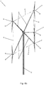
- Figs. 6a and 6b are perspective views of a multirotor wind turbine 1 according to a sixth embodiment of the invention, seen from two different angles.
- the multirotor wind turbine 1 of Figs. 6a and 6b is very similar to the multirotor wind turbine 1 of Figs. 5a and 5b , and it will therefore not be described in further detail here.
- the multirotor wind turbine 1 of Figs. 6a and 6b comprises an additional energy generating unit 7 comprising an upwind rotor 8.
- This energy generating unit 7 is arranged directly in front of the tower structure 2, along the direction of the incoming wind, and with its centre of gravity at a vertical level corresponding to the vertical level of the common point of connection between the arms 3 and the tower structure 2. Thereby the total power production of the multirotor wind turbine 1 is increased without risking that any of the downwind rotors 6 are arranged in the wake of the additional upwind rotor 8.
- Figs. 7a-7d are schematic illustrations of configurations of energy generating units.
- the configurations shown in Figs. 7a and 7c comprises one downwind rotor 6 and two upwind rotors 8.
- the configuration shown in Fig. 7d comprises two downwind rotors 6 and two upwind rotors 8, mounted on respective arms 3.
- the pair of arms 3 supporting the upwind rotors 8 may be mounted to and supported by a first tow structure 2
- the pair of arms 3 supporting the downwind rotors 6 may be mounted to and supported by a second structure 2.
- both pairs of arms 3 may be mounted to and supported by one and the same tower structure 2.
- Fig. 7b illustrates a side view of the configuration of Fig. 7c .
- Figs. 7a, 7c and 7d the direction of the incoming wind is illustrated by arrow 10.
Landscapes
- Engineering & Computer Science (AREA)
- Life Sciences & Earth Sciences (AREA)
- Sustainable Development (AREA)
- Sustainable Energy (AREA)
- Chemical & Material Sciences (AREA)
- Combustion & Propulsion (AREA)
- Mechanical Engineering (AREA)
- General Engineering & Computer Science (AREA)
- Wind Motors (AREA)
Claims (10)
- Windkraftanlage mit mehreren Rotoren (1), umfassend eine Turmstruktur (2) und mindestens eine Lasttragestruktur (3, 4) wobei jede Lasttragestruktur (3, 4) eingerichtet ist, um zwei oder mehr erste Leistungserzeugungseinheiten (5, 7) zu tragen und um mit der Turmstruktur (2) verbunden zu sein, wobei jede erste Leistungserzeugungseinheit (5, 7) einen ersten Rotor (6, 8) umfasst und jede erste Leistungserzeugungseinheit (5, 7) einen Schwerpunkt aufweist,
dadurch gekennzeichnet, dass mindestens zwei der ersten Rotoren leeseitige Rotoren (6) sind, wobei die ersten Leistungserzeugungseinheiten (5), die die mindestens zwei leeseitigen Rotoren (6) umfassen, mit ihren jeweiligen Schwerpunkten bei einem ersten Abstand hinter der Turmstruktur (2) entlang einer Richtung des eingehenden Windes im Wesentlichen auf derselben vertikalen Höhe und an entgegengesetzten Seiten der Turmstruktur (2) bei im Wesentlichen demselben zweiten Abstand zur Turmstruktur (2) entlang einer Richtung im Wesentlichen senkrecht zur Richtung des eingehenden Windes eingerichtet sind. - Windkraftanlage mit mehreren Rotoren (1) nach Anspruch 1, wobei mindestens eine der mindestens einen Lasttragestruktur (3, 4) eingerichtet ist, um mindestens eine zweite Leistungserzeugungseinheit (7) zu tragen, wobei die mindestens eine zweite Leistungserzeugungseinheit (7) ein windwärts gelegener Rotor (8) ist, der Schwerpunkt mindestens einer der zweiten Leistungserzeugungseinheiten (7) bei einem dritten Abstand von der Turmstruktur (2) entlang der Richtung des eingehenden Windes eingerichtet ist.
- Windkraftanlage mit mehreren Rotoren (1) nach Anspruch 2, wobei der Schwerpunkt mindestens einer der zweiten Leistungserzeugungseinheiten (7) auf einer vertikalen Höhe eingerichtet ist, die sich von der vertikalen Höhe mindestens einer der mindestens zwei ersten Leistungserzeugungseinheiten (5) unterscheidet.
- Windkraftanlage mit mehreren Rotoren (1) nach Anspruch 2 oder 3, wobei mindestens eine Lasttragestruktur (3, 4) eingerichtet ist, um mindestens zwei zweite Leistungserzeugungseinheiten (7) zu tragen, wobei die mindestens zwei zweiten Leistungserzeugungseinheiten (7) windwärts gelegene Rotoren tragen, die mindestens zwei zweiten Leistungserzeugungseinheiten (7) mit ihren Schwerpunkten in einer gemeinsamen vertikalen Ebene eingerichtet sind, die sich im Wesentlichen senkrecht zur Richtung des eingehenden Windes erstreckt, beim dritten Abstand von der Turmstruktur (2) entlang der Richtung des eingehenden Windes.
- Windkraftanlage mit mehreren Rotoren (1) nach Anspruch 4, wobei mindestens eine zweite Leistungserzeugungseinheit (7), die einen windwärts gelegenen Rotor (8) umfasst, mit ihrem Schwerpunkt über der vertikalen Höhe mindestens einer ersten Leistungserzeugungseinheit (5), die einen leeseitigen Rotor (6) umfasst, eingerichtet ist, und mindestens eine zweite Leistungserzeugungseinheit (7), die einen windwärts gelegenen Rotor (8) umfasst, mit ihrem Schwerpunkt unter der vertikalen Höhe mindestens einer ersten Leistungserzeugungseinheit (5), die einen leeseitigen Rotor (6) umfasst, eingerichtet ist.
- Windkraftanlage mit mehreren Rotoren (1) nach Anspruch 4 oder 5, wobei die Positionen der Schwerpunkte für zwei erste Leistungserzeugungseinheiten (5), die leeseitige Rotoren (6) umfassen, und zwei zweite Leistungserzeugungseinheiten (7), die windwärts gelegene Rotoren (8) umfassen, Ecken eines regelmäßigen Tetraeders bilden.
- Windkraftanlage mit mehreren Rotoren (1) nach einem der vorstehenden Ansprüche, wobei mindestens eine Lasttragestruktur (3, 4) eingerichtet ist, um mindestens drei erste Leistungserzeugungseinheiten (5), die einen leeseitigen Rotor (6) umfassen, und mindestens zwei zweite Leistungsenergieeinheiten (7), die einen windwärts gelegenen Rotor (8) umfassen, zu tragen, und wobei die Lasttragestruktur (3, 4) mindestens drei Arme (3) umfasst, wobei jeder Arm (3) eine erste Leistungserzeugungseinheit (5) trägt, die einen leeseitigen Rotor (6) umfasst, und eine zweite Leistungserzeugungseinheit (7), die einen windwärts gelegenen Rotor (8) umfasst, und wobei jeder Arm (3) über ein gemeinsames Verbindungsteil mit der Turmstruktur (2) verbunden ist.
- Windkraftanlage mit mehreren Rotoren (1) nach einem der vorstehenden Ansprüche, wobei mindestens eine Lasttragestruktur mindestens zwei Hauptstrukturen (3) und mindestens zwei Nebenstrukturen (4) umfasst, und wobei Schwerkraft, die auf die ersten und/oder zweiten Leistungserzeugungseinheiten (5, 7) wirkt, die von der Lasttragestruktur (3, 4) getragen werden, Drücken bei den Hauptstrukturen (3) und Ziehen bei den Nebenstrukturen (4) bewirkt.
- Windkraftanlage mit mehreren Rotoren (1) nach Anspruch 8, wobei die Hauptstrukturen (3) in der Form eines oder mehrerer Druckstäbe vorliegen.
- Windkraftanlage mit mehreren Rotoren (1) nach Anspruch 8 oder 9, wobei die Nebenstrukturen (4) in der Form eines oder mehrerer Zugglieder vorliegen.
Applications Claiming Priority (3)
| Application Number | Priority Date | Filing Date | Title |
|---|---|---|---|
| US201662322353P | 2016-04-14 | 2016-04-14 | |
| DKPA201670311 | 2016-05-10 | ||
| PCT/DK2017/050104 WO2017178025A1 (en) | 2016-04-14 | 2017-04-04 | A multi rotor wind turbine |
Publications (2)
| Publication Number | Publication Date |
|---|---|
| EP3443220A1 EP3443220A1 (de) | 2019-02-20 |
| EP3443220B1 true EP3443220B1 (de) | 2021-01-13 |
Family
ID=60041380
Family Applications (1)
| Application Number | Title | Priority Date | Filing Date |
|---|---|---|---|
| EP17717072.7A Active EP3443220B1 (de) | 2016-04-14 | 2017-04-04 | Windturbine mit mehreren rotoren |
Country Status (4)
| Country | Link |
|---|---|
| US (1) | US10697424B2 (de) |
| EP (1) | EP3443220B1 (de) |
| CN (1) | CN109219701B (de) |
| WO (1) | WO2017178025A1 (de) |
Families Citing this family (13)
| Publication number | Priority date | Publication date | Assignee | Title |
|---|---|---|---|---|
| ES2832493T3 (es) * | 2017-03-01 | 2021-06-10 | Vestas Wind Sys As | Monitorización de rendimiento de un sistema de turbina eólica multirrotor |
| EP3642476B1 (de) | 2017-06-19 | 2022-06-01 | Vestas Wind Systems A/S | Mehrrotorwindturbine mit spanndrähten |
| US10724503B2 (en) * | 2017-11-26 | 2020-07-28 | Ahmad Abdallah Al-Jassem Al-Qanaei | Rotating support for multiple wind turbines |
| CN109962493A (zh) * | 2017-12-25 | 2019-07-02 | 新疆金风科技股份有限公司 | 用于优化风力发电机组的载荷的方法和装置 |
| KR102038023B1 (ko) * | 2018-02-14 | 2019-10-29 | 두산중공업 주식회사 | 멀티형 풍력 발전기 |
| KR102145052B1 (ko) * | 2018-12-04 | 2020-08-14 | 두산중공업 주식회사 | 멀티형 풍력 발전기 |
| WO2021121500A1 (en) * | 2019-12-20 | 2021-06-24 | Vestas Wind Systems A/S | Mitigation of nacelle drop by tension wire |
| CN111102136A (zh) * | 2019-12-27 | 2020-05-05 | 李国坤 | 一种永磁悬浮组合型风光发电系统 |
| US12037982B2 (en) | 2020-06-12 | 2024-07-16 | Vestas Wind Systems A/S | Toe angle control for multirotor wind turbines |
| EP3945207A1 (de) * | 2020-07-30 | 2022-02-02 | Siemens Gamesa Renewable Energy Innovation & Technology S.L. | Gittergerüst |
| WO2022083835A1 (en) | 2020-10-23 | 2022-04-28 | Vestas Wind Systems A/S | Multi-rotor wind turbine yaw control |
| CN113279901A (zh) * | 2021-07-01 | 2021-08-20 | 中国华能集团清洁能源技术研究院有限公司 | 一种机舱带有辅助支撑结构的双风轮风电机组 |
| CN114370378B (zh) * | 2022-01-17 | 2024-10-22 | 苏州新三力风电科技有限公司 | 一种多叶轮风电系统的支撑结构 |
Family Cites Families (20)
| Publication number | Priority date | Publication date | Assignee | Title |
|---|---|---|---|---|
| US4110631A (en) * | 1974-07-17 | 1978-08-29 | Wind Power Systems, Inc. | Wind-driven generator |
| US4710100A (en) * | 1983-11-21 | 1987-12-01 | Oliver Laing | Wind machine |
| KR960007401B1 (ko) * | 1994-06-27 | 1996-05-31 | 신찬 | 복합 입력형 풍력장치(The Multi-unit Rotor Blade system Integrated wind Turbine) |
| NL1005089C2 (nl) | 1997-01-24 | 1998-01-28 | Beheermaatschappij P Buitendij | Inrichting voor het met behulp van wind opwekken van elektrische energie. |
| NL1006496C2 (nl) * | 1997-07-07 | 1999-01-08 | Lagerwey Windturbine B V | Windmolen-eiland. |
| CZ290785B6 (cs) | 1998-12-16 | 2002-10-16 | Obec Domanín | Zařízení pro vyuľívání energie větru |
| DE10205988B4 (de) * | 2002-02-14 | 2006-02-09 | Aloys Wobben | Windenergieanlage |
| US6749399B2 (en) * | 2002-03-07 | 2004-06-15 | Ocean Wind Energy Systems | Vertical array wind turbine |
| JP4098724B2 (ja) | 2002-03-08 | 2008-06-11 | オーシャン・ウィンド・エナジー・システムズ・インコーポレイテッド | 沖合風力タービン |
| FR2868483B1 (fr) * | 2004-03-30 | 2006-04-28 | Gregoire Alexandroff | Moyens de realisation d'un type d'eolienne quadrirotor et dispositif d'implantation de ces eoliennes en parc offshore |
| JP2006322383A (ja) | 2005-05-19 | 2006-11-30 | Ripooto Service Hokkaido:Kk | ツインロ−タ式風力発電装置 |
| GB2443886B8 (en) | 2006-11-20 | 2016-02-17 | Michael Torr Todman | Multi-rotor wind turbine |
| US20090196748A1 (en) | 2008-02-05 | 2009-08-06 | Greenward Technologies, Inc. | Wind turbine improvements |
| WO2010098813A1 (en) * | 2009-02-28 | 2010-09-02 | Ener2 Llc | Wind energy device |
| CN102162429A (zh) * | 2010-09-29 | 2011-08-24 | 道达(上海)风电投资有限公司 | 风力发电装置 |
| US8952558B2 (en) | 2010-09-29 | 2015-02-10 | Jiangsu Daoda Offshore Wind Construction Technology Co., Limited | Wind generating device |
| JP5807963B2 (ja) * | 2011-05-02 | 2015-11-10 | 石嶺 末美 | 風車装置 |
| DE202012013622U1 (de) * | 2011-11-17 | 2018-09-07 | Doosan Heavy Industries & Construction Co., Ltd. | Mehrfach-Windkraftanlage |
| US10138866B2 (en) * | 2014-11-14 | 2018-11-27 | Riamwind Co., Ltd. | Fluid power generation method and fluid power generation device |
| WO2016128005A1 (en) * | 2015-02-12 | 2016-08-18 | Vestas Wind Systems A/S | Control system for wind turbine having multiple rotors arranged to control support arm orientation |
-
2017
- 2017-04-04 EP EP17717072.7A patent/EP3443220B1/de active Active
- 2017-04-04 WO PCT/DK2017/050104 patent/WO2017178025A1/en not_active Ceased
- 2017-04-04 US US16/085,760 patent/US10697424B2/en not_active Expired - Fee Related
- 2017-04-04 CN CN201780034647.8A patent/CN109219701B/zh active Active
Non-Patent Citations (1)
| Title |
|---|
| None * |
Also Published As
| Publication number | Publication date |
|---|---|
| US20190048847A1 (en) | 2019-02-14 |
| EP3443220A1 (de) | 2019-02-20 |
| CN109219701B (zh) | 2020-07-07 |
| WO2017178025A1 (en) | 2017-10-19 |
| CN109219701A (zh) | 2019-01-15 |
| US10697424B2 (en) | 2020-06-30 |
Similar Documents
| Publication | Publication Date | Title |
|---|---|---|
| US10697424B2 (en) | Multirotor wind turbine | |
| EP3394429B1 (de) | Eine lasttragender struktur für eine multirotor-windturbine | |
| US8011887B2 (en) | Rotor blade assembly | |
| EP2505823B1 (de) | Transportrahmen für eine Gondel/Rotornabeneinheit einer Windturbine, Transportverfahren und Montage einer Gondel/Rotornabeneinheit | |
| US20080253892A1 (en) | Tension Wheel Hub in a Rotor System for Wind and Water Turbines | |
| US20120051914A1 (en) | Cable-stayed rotor for wind and water turbines | |
| US8858174B2 (en) | Wind turbine torque-speed control | |
| US20090196748A1 (en) | Wind turbine improvements | |
| EP3724493B1 (de) | Windenergiepark mit schrägseilwindturbinen | |
| US20110037271A1 (en) | Wind turbine system and modular wind turbine unit therefor | |
| EP3564525B1 (de) | Antriebsvorrichtung eines windenergiegenerators mit vertikaler welle für selbstverstellbaren propeller und windenergiegenerator | |
| CN104295445A (zh) | 用于控制风力涡轮机中的负载的方法 | |
| JP7588456B2 (ja) | 調整可能なブレードを有する抗力兼揚力ベースの風力タービンシステム | |
| KR101406575B1 (ko) | 풍력발전장치 | |
| WO2017186244A1 (en) | A method for erecting a multirotor wind turbine with elevated hub height | |
| US8092182B2 (en) | Wind turbine blade support structure | |
| KR20140089212A (ko) | 보강 구조물을 포함하는 풍력 발전기 | |
| JP2006077747A (ja) | 複式一枚羽根風力発電装置 | |
| CN114370378B (zh) | 一种多叶轮风电系统的支撑结构 | |
| CN114483458A (zh) | 一种三机头风力发电机组及安装方法 | |
| US20040184909A1 (en) | Multi-rotor blade stackable vertical axis windmill | |
| CN114483487A (zh) | 用于风力涡轮的机舱及在该机舱中支承转矩的方法 | |
| ES2845004T3 (es) | Turbina eólica multirrotor | |
| KR101250260B1 (ko) | 멀티형 풍력 발전 장치 | |
| JP6001036B2 (ja) | 風力発電装置 |
Legal Events
| Date | Code | Title | Description |
|---|---|---|---|
| STAA | Information on the status of an ep patent application or granted ep patent |
Free format text: STATUS: UNKNOWN |
|
| STAA | Information on the status of an ep patent application or granted ep patent |
Free format text: STATUS: THE INTERNATIONAL PUBLICATION HAS BEEN MADE |
|
| PUAI | Public reference made under article 153(3) epc to a published international application that has entered the european phase |
Free format text: ORIGINAL CODE: 0009012 |
|
| STAA | Information on the status of an ep patent application or granted ep patent |
Free format text: STATUS: REQUEST FOR EXAMINATION WAS MADE |
|
| 17P | Request for examination filed |
Effective date: 20181113 |
|
| AK | Designated contracting states |
Kind code of ref document: A1 Designated state(s): AL AT BE BG CH CY CZ DE DK EE ES FI FR GB GR HR HU IE IS IT LI LT LU LV MC MK MT NL NO PL PT RO RS SE SI SK SM TR |
|
| AX | Request for extension of the european patent |
Extension state: BA ME |
|
| DAV | Request for validation of the european patent (deleted) | ||
| DAX | Request for extension of the european patent (deleted) | ||
| GRAP | Despatch of communication of intention to grant a patent |
Free format text: ORIGINAL CODE: EPIDOSNIGR1 |
|
| STAA | Information on the status of an ep patent application or granted ep patent |
Free format text: STATUS: GRANT OF PATENT IS INTENDED |
|
| INTG | Intention to grant announced |
Effective date: 20200911 |
|
| GRAS | Grant fee paid |
Free format text: ORIGINAL CODE: EPIDOSNIGR3 |
|
| GRAA | (expected) grant |
Free format text: ORIGINAL CODE: 0009210 |
|
| STAA | Information on the status of an ep patent application or granted ep patent |
Free format text: STATUS: THE PATENT HAS BEEN GRANTED |
|
| AK | Designated contracting states |
Kind code of ref document: B1 Designated state(s): AL AT BE BG CH CY CZ DE DK EE ES FI FR GB GR HR HU IE IS IT LI LT LU LV MC MK MT NL NO PL PT RO RS SE SI SK SM TR |
|
| REG | Reference to a national code |
Ref country code: GB Ref legal event code: FG4D |
|
| REG | Reference to a national code |
Ref country code: CH Ref legal event code: EP |
|
| REG | Reference to a national code |
Ref country code: IE Ref legal event code: FG4D |
|
| REG | Reference to a national code |
Ref country code: DE Ref legal event code: R096 Ref document number: 602017031343 Country of ref document: DE |
|
| REG | Reference to a national code |
Ref country code: AT Ref legal event code: REF Ref document number: 1354751 Country of ref document: AT Kind code of ref document: T Effective date: 20210215 |
|
| REG | Reference to a national code |
Ref country code: AT Ref legal event code: MK05 Ref document number: 1354751 Country of ref document: AT Kind code of ref document: T Effective date: 20210113 |
|
| REG | Reference to a national code |
Ref country code: NL Ref legal event code: MP Effective date: 20210113 |
|
| REG | Reference to a national code |
Ref country code: LT Ref legal event code: MG9D |
|
| REG | Reference to a national code |
Ref country code: ES Ref legal event code: FG2A Ref document number: 2845004 Country of ref document: ES Kind code of ref document: T3 Effective date: 20210723 |
|
| PG25 | Lapsed in a contracting state [announced via postgrant information from national office to epo] |
Ref country code: NO Free format text: LAPSE BECAUSE OF FAILURE TO SUBMIT A TRANSLATION OF THE DESCRIPTION OR TO PAY THE FEE WITHIN THE PRESCRIBED TIME-LIMIT Effective date: 20210413 Ref country code: PT Free format text: LAPSE BECAUSE OF FAILURE TO SUBMIT A TRANSLATION OF THE DESCRIPTION OR TO PAY THE FEE WITHIN THE PRESCRIBED TIME-LIMIT Effective date: 20210513 Ref country code: HR Free format text: LAPSE BECAUSE OF FAILURE TO SUBMIT A TRANSLATION OF THE DESCRIPTION OR TO PAY THE FEE WITHIN THE PRESCRIBED TIME-LIMIT Effective date: 20210113 Ref country code: GR Free format text: LAPSE BECAUSE OF FAILURE TO SUBMIT A TRANSLATION OF THE DESCRIPTION OR TO PAY THE FEE WITHIN THE PRESCRIBED TIME-LIMIT Effective date: 20210414 Ref country code: FI Free format text: LAPSE BECAUSE OF FAILURE TO SUBMIT A TRANSLATION OF THE DESCRIPTION OR TO PAY THE FEE WITHIN THE PRESCRIBED TIME-LIMIT Effective date: 20210113 Ref country code: BG Free format text: LAPSE BECAUSE OF FAILURE TO SUBMIT A TRANSLATION OF THE DESCRIPTION OR TO PAY THE FEE WITHIN THE PRESCRIBED TIME-LIMIT Effective date: 20210413 Ref country code: LT Free format text: LAPSE BECAUSE OF FAILURE TO SUBMIT A TRANSLATION OF THE DESCRIPTION OR TO PAY THE FEE WITHIN THE PRESCRIBED TIME-LIMIT Effective date: 20210113 |
|
| PG25 | Lapsed in a contracting state [announced via postgrant information from national office to epo] |
Ref country code: AT Free format text: LAPSE BECAUSE OF FAILURE TO SUBMIT A TRANSLATION OF THE DESCRIPTION OR TO PAY THE FEE WITHIN THE PRESCRIBED TIME-LIMIT Effective date: 20210113 Ref country code: RS Free format text: LAPSE BECAUSE OF FAILURE TO SUBMIT A TRANSLATION OF THE DESCRIPTION OR TO PAY THE FEE WITHIN THE PRESCRIBED TIME-LIMIT Effective date: 20210113 Ref country code: LV Free format text: LAPSE BECAUSE OF FAILURE TO SUBMIT A TRANSLATION OF THE DESCRIPTION OR TO PAY THE FEE WITHIN THE PRESCRIBED TIME-LIMIT Effective date: 20210113 Ref country code: PL Free format text: LAPSE BECAUSE OF FAILURE TO SUBMIT A TRANSLATION OF THE DESCRIPTION OR TO PAY THE FEE WITHIN THE PRESCRIBED TIME-LIMIT Effective date: 20210113 Ref country code: SE Free format text: LAPSE BECAUSE OF FAILURE TO SUBMIT A TRANSLATION OF THE DESCRIPTION OR TO PAY THE FEE WITHIN THE PRESCRIBED TIME-LIMIT Effective date: 20210113 |
|
| PG25 | Lapsed in a contracting state [announced via postgrant information from national office to epo] |
Ref country code: IS Free format text: LAPSE BECAUSE OF FAILURE TO SUBMIT A TRANSLATION OF THE DESCRIPTION OR TO PAY THE FEE WITHIN THE PRESCRIBED TIME-LIMIT Effective date: 20210513 |
|
| REG | Reference to a national code |
Ref country code: DE Ref legal event code: R097 Ref document number: 602017031343 Country of ref document: DE |
|
| PG25 | Lapsed in a contracting state [announced via postgrant information from national office to epo] |
Ref country code: SM Free format text: LAPSE BECAUSE OF FAILURE TO SUBMIT A TRANSLATION OF THE DESCRIPTION OR TO PAY THE FEE WITHIN THE PRESCRIBED TIME-LIMIT Effective date: 20210113 Ref country code: CZ Free format text: LAPSE BECAUSE OF FAILURE TO SUBMIT A TRANSLATION OF THE DESCRIPTION OR TO PAY THE FEE WITHIN THE PRESCRIBED TIME-LIMIT Effective date: 20210113 Ref country code: EE Free format text: LAPSE BECAUSE OF FAILURE TO SUBMIT A TRANSLATION OF THE DESCRIPTION OR TO PAY THE FEE WITHIN THE PRESCRIBED TIME-LIMIT Effective date: 20210113 |
|
| PLBE | No opposition filed within time limit |
Free format text: ORIGINAL CODE: 0009261 |
|
| STAA | Information on the status of an ep patent application or granted ep patent |
Free format text: STATUS: NO OPPOSITION FILED WITHIN TIME LIMIT |
|
| PG25 | Lapsed in a contracting state [announced via postgrant information from national office to epo] |
Ref country code: MC Free format text: LAPSE BECAUSE OF FAILURE TO SUBMIT A TRANSLATION OF THE DESCRIPTION OR TO PAY THE FEE WITHIN THE PRESCRIBED TIME-LIMIT Effective date: 20210113 Ref country code: SK Free format text: LAPSE BECAUSE OF FAILURE TO SUBMIT A TRANSLATION OF THE DESCRIPTION OR TO PAY THE FEE WITHIN THE PRESCRIBED TIME-LIMIT Effective date: 20210113 Ref country code: DK Free format text: LAPSE BECAUSE OF FAILURE TO SUBMIT A TRANSLATION OF THE DESCRIPTION OR TO PAY THE FEE WITHIN THE PRESCRIBED TIME-LIMIT Effective date: 20210113 Ref country code: RO Free format text: LAPSE BECAUSE OF FAILURE TO SUBMIT A TRANSLATION OF THE DESCRIPTION OR TO PAY THE FEE WITHIN THE PRESCRIBED TIME-LIMIT Effective date: 20210113 |
|
| 26N | No opposition filed |
Effective date: 20211014 |
|
| PG25 | Lapsed in a contracting state [announced via postgrant information from national office to epo] |
Ref country code: LU Free format text: LAPSE BECAUSE OF NON-PAYMENT OF DUE FEES Effective date: 20210404 |
|
| REG | Reference to a national code |
Ref country code: BE Ref legal event code: MM Effective date: 20210430 |
|
| PG25 | Lapsed in a contracting state [announced via postgrant information from national office to epo] |
Ref country code: LI Free format text: LAPSE BECAUSE OF NON-PAYMENT OF DUE FEES Effective date: 20210430 Ref country code: CH Free format text: LAPSE BECAUSE OF NON-PAYMENT OF DUE FEES Effective date: 20210430 Ref country code: AL Free format text: LAPSE BECAUSE OF FAILURE TO SUBMIT A TRANSLATION OF THE DESCRIPTION OR TO PAY THE FEE WITHIN THE PRESCRIBED TIME-LIMIT Effective date: 20210113 |
|
| PG25 | Lapsed in a contracting state [announced via postgrant information from national office to epo] |
Ref country code: SI Free format text: LAPSE BECAUSE OF FAILURE TO SUBMIT A TRANSLATION OF THE DESCRIPTION OR TO PAY THE FEE WITHIN THE PRESCRIBED TIME-LIMIT Effective date: 20210113 |
|
| PG25 | Lapsed in a contracting state [announced via postgrant information from national office to epo] |
Ref country code: IT Free format text: LAPSE BECAUSE OF FAILURE TO SUBMIT A TRANSLATION OF THE DESCRIPTION OR TO PAY THE FEE WITHIN THE PRESCRIBED TIME-LIMIT Effective date: 20210113 Ref country code: IE Free format text: LAPSE BECAUSE OF NON-PAYMENT OF DUE FEES Effective date: 20210404 |
|
| PG25 | Lapsed in a contracting state [announced via postgrant information from national office to epo] |
Ref country code: IS Free format text: LAPSE BECAUSE OF FAILURE TO SUBMIT A TRANSLATION OF THE DESCRIPTION OR TO PAY THE FEE WITHIN THE PRESCRIBED TIME-LIMIT Effective date: 20210513 |
|
| PG25 | Lapsed in a contracting state [announced via postgrant information from national office to epo] |
Ref country code: BE Free format text: LAPSE BECAUSE OF NON-PAYMENT OF DUE FEES Effective date: 20210430 |
|
| P01 | Opt-out of the competence of the unified patent court (upc) registered |
Effective date: 20230521 |
|
| PG25 | Lapsed in a contracting state [announced via postgrant information from national office to epo] |
Ref country code: NL Free format text: LAPSE BECAUSE OF NON-PAYMENT OF DUE FEES Effective date: 20210113 Ref country code: CY Free format text: LAPSE BECAUSE OF FAILURE TO SUBMIT A TRANSLATION OF THE DESCRIPTION OR TO PAY THE FEE WITHIN THE PRESCRIBED TIME-LIMIT Effective date: 20210113 |
|
| PG25 | Lapsed in a contracting state [announced via postgrant information from national office to epo] |
Ref country code: HU Free format text: LAPSE BECAUSE OF FAILURE TO SUBMIT A TRANSLATION OF THE DESCRIPTION OR TO PAY THE FEE WITHIN THE PRESCRIBED TIME-LIMIT; INVALID AB INITIO Effective date: 20170404 |
|
| PG25 | Lapsed in a contracting state [announced via postgrant information from national office to epo] |
Ref country code: MK Free format text: LAPSE BECAUSE OF FAILURE TO SUBMIT A TRANSLATION OF THE DESCRIPTION OR TO PAY THE FEE WITHIN THE PRESCRIBED TIME-LIMIT Effective date: 20210113 |
|
| PG25 | Lapsed in a contracting state [announced via postgrant information from national office to epo] |
Ref country code: TR Free format text: LAPSE BECAUSE OF FAILURE TO SUBMIT A TRANSLATION OF THE DESCRIPTION OR TO PAY THE FEE WITHIN THE PRESCRIBED TIME-LIMIT Effective date: 20210113 |
|
| PG25 | Lapsed in a contracting state [announced via postgrant information from national office to epo] |
Ref country code: MT Free format text: LAPSE BECAUSE OF FAILURE TO SUBMIT A TRANSLATION OF THE DESCRIPTION OR TO PAY THE FEE WITHIN THE PRESCRIBED TIME-LIMIT Effective date: 20210113 |
|
| PGFP | Annual fee paid to national office [announced via postgrant information from national office to epo] |
Ref country code: GB Payment date: 20260225 Year of fee payment: 10 |
|
| PGFP | Annual fee paid to national office [announced via postgrant information from national office to epo] |
Ref country code: ES Payment date: 20260511 Year of fee payment: 10 |
|
| PGFP | Annual fee paid to national office [announced via postgrant information from national office to epo] |
Ref country code: DE Payment date: 20260421 Year of fee payment: 10 |
|
| PGFP | Annual fee paid to national office [announced via postgrant information from national office to epo] |
Ref country code: FR Payment date: 20260423 Year of fee payment: 10 |