EP3443402B1 - Guide d'onde avec champ visuel élargi - Google Patents
Guide d'onde avec champ visuel élargi Download PDFInfo
- Publication number
- EP3443402B1 EP3443402B1 EP17718287.0A EP17718287A EP3443402B1 EP 3443402 B1 EP3443402 B1 EP 3443402B1 EP 17718287 A EP17718287 A EP 17718287A EP 3443402 B1 EP3443402 B1 EP 3443402B1
- Authority
- EP
- European Patent Office
- Prior art keywords
- coupler
- fov
- optical waveguide
- input
- light corresponding
- Prior art date
- Legal status (The legal status is an assumption and is not a legal conclusion. Google has not performed a legal analysis and makes no representation as to the accuracy of the status listed.)
- Active
Links
Images


Classifications
-
- G—PHYSICS
- G02—OPTICS
- G02B—OPTICAL ELEMENTS, SYSTEMS OR APPARATUS
- G02B27/00—Optical systems or apparatus not provided for by any of the groups G02B1/00 - G02B26/00, G02B30/00
- G02B27/01—Head-up displays
- G02B27/017—Head mounted
- G02B27/0172—Head mounted characterised by optical features
-
- G—PHYSICS
- G02—OPTICS
- G02B—OPTICAL ELEMENTS, SYSTEMS OR APPARATUS
- G02B27/00—Optical systems or apparatus not provided for by any of the groups G02B1/00 - G02B26/00, G02B30/00
- G02B27/0081—Optical systems or apparatus not provided for by any of the groups G02B1/00 - G02B26/00, G02B30/00 with means for altering, e.g. enlarging, the entrance or exit pupil
-
- G—PHYSICS
- G02—OPTICS
- G02B—OPTICAL ELEMENTS, SYSTEMS OR APPARATUS
- G02B27/00—Optical systems or apparatus not provided for by any of the groups G02B1/00 - G02B26/00, G02B30/00
- G02B27/42—Diffraction optics, i.e. systems including a diffractive element being designed for providing a diffractive effect
- G02B27/44—Grating systems; Zone plate systems
-
- G—PHYSICS
- G02—OPTICS
- G02B—OPTICAL ELEMENTS, SYSTEMS OR APPARATUS
- G02B30/00—Optical systems or apparatus for producing three-dimensional [3D] effects, e.g. stereoscopic images
- G02B30/20—Optical systems or apparatus for producing three-dimensional [3D] effects, e.g. stereoscopic images by providing first and second parallax images to an observer's left and right eyes
- G02B30/34—Stereoscopes providing a stereoscopic pair of separated images corresponding to parallactically displaced views of the same object, e.g. three-dimensional [3D] slide viewers
- G02B30/35—Stereoscopes providing a stereoscopic pair of separated images corresponding to parallactically displaced views of the same object, e.g. three-dimensional [3D] slide viewers using reflective optical elements in the optical path between the images and the observer
-
- G—PHYSICS
- G02—OPTICS
- G02B—OPTICAL ELEMENTS, SYSTEMS OR APPARATUS
- G02B5/00—Optical elements other than lenses
- G02B5/18—Diffraction gratings
- G02B5/1814—Diffraction gratings structurally combined with one or more further optical elements, e.g. lenses, mirrors, prisms or other diffraction gratings
- G02B5/1819—Plural gratings positioned on the same surface, e.g. array of gratings
-
- G—PHYSICS
- G02—OPTICS
- G02B—OPTICAL ELEMENTS, SYSTEMS OR APPARATUS
- G02B6/00—Light guides; Structural details of arrangements comprising light guides and other optical elements, e.g. couplings
- G02B6/0001—Light guides; Structural details of arrangements comprising light guides and other optical elements, e.g. couplings specially adapted for lighting devices or systems
- G02B6/0011—Light guides; Structural details of arrangements comprising light guides and other optical elements, e.g. couplings specially adapted for lighting devices or systems the light guides being planar or of plate-like form
- G02B6/0013—Means for improving the coupling-in of light from the light source into the light guide
- G02B6/0023—Means for improving the coupling-in of light from the light source into the light guide provided by one optical element, or plurality thereof, placed between the light guide and the light source, or around the light source
- G02B6/0026—Wavelength selective element, sheet or layer, e.g. filter or grating
-
- G—PHYSICS
- G02—OPTICS
- G02B—OPTICAL ELEMENTS, SYSTEMS OR APPARATUS
- G02B6/00—Light guides; Structural details of arrangements comprising light guides and other optical elements, e.g. couplings
- G02B6/0001—Light guides; Structural details of arrangements comprising light guides and other optical elements, e.g. couplings specially adapted for lighting devices or systems
- G02B6/0011—Light guides; Structural details of arrangements comprising light guides and other optical elements, e.g. couplings specially adapted for lighting devices or systems the light guides being planar or of plate-like form
- G02B6/0033—Means for improving the coupling-out of light from the light guide
- G02B6/005—Means for improving the coupling-out of light from the light guide provided by one optical element, or plurality thereof, placed on the light output side of the light guide
-
- G—PHYSICS
- G02—OPTICS
- G02F—OPTICAL DEVICES OR ARRANGEMENTS FOR THE CONTROL OF LIGHT BY MODIFICATION OF THE OPTICAL PROPERTIES OF THE MEDIA OF THE ELEMENTS INVOLVED THEREIN; NON-LINEAR OPTICS; FREQUENCY-CHANGING OF LIGHT; OPTICAL LOGIC ELEMENTS; OPTICAL ANALOGUE/DIGITAL CONVERTERS
- G02F1/00—Devices or arrangements for the control of the intensity, colour, phase, polarisation or direction of light arriving from an independent light source, e.g. switching, gating or modulating; Non-linear optics
- G02F1/29—Devices or arrangements for the control of the intensity, colour, phase, polarisation or direction of light arriving from an independent light source, e.g. switching, gating or modulating; Non-linear optics for the control of the position or the direction of light beams, i.e. deflection
- G02F1/292—Devices or arrangements for the control of the intensity, colour, phase, polarisation or direction of light arriving from an independent light source, e.g. switching, gating or modulating; Non-linear optics for the control of the position or the direction of light beams, i.e. deflection by controlled diffraction or phased-array beam steering
-
- G—PHYSICS
- G02—OPTICS
- G02F—OPTICAL DEVICES OR ARRANGEMENTS FOR THE CONTROL OF LIGHT BY MODIFICATION OF THE OPTICAL PROPERTIES OF THE MEDIA OF THE ELEMENTS INVOLVED THEREIN; NON-LINEAR OPTICS; FREQUENCY-CHANGING OF LIGHT; OPTICAL LOGIC ELEMENTS; OPTICAL ANALOGUE/DIGITAL CONVERTERS
- G02F1/00—Devices or arrangements for the control of the intensity, colour, phase, polarisation or direction of light arriving from an independent light source, e.g. switching, gating or modulating; Non-linear optics
- G02F1/29—Devices or arrangements for the control of the intensity, colour, phase, polarisation or direction of light arriving from an independent light source, e.g. switching, gating or modulating; Non-linear optics for the control of the position or the direction of light beams, i.e. deflection
- G02F1/295—Analog deflection from or in an optical waveguide structure]
-
- H—ELECTRICITY
- H04—ELECTRIC COMMUNICATION TECHNIQUE
- H04N—PICTORIAL COMMUNICATION, e.g. TELEVISION
- H04N13/00—Stereoscopic video systems; Multi-view video systems; Details thereof
- H04N13/30—Image reproducers
- H04N13/332—Displays for viewing with the aid of special glasses or head-mounted displays [HMD]
- H04N13/344—Displays for viewing with the aid of special glasses or head-mounted displays [HMD] with head-mounted left-right displays
-
- G—PHYSICS
- G02—OPTICS
- G02B—OPTICAL ELEMENTS, SYSTEMS OR APPARATUS
- G02B5/00—Optical elements other than lenses
- G02B5/18—Diffraction gratings
- G02B2005/1804—Transmission gratings
-
- G—PHYSICS
- G02—OPTICS
- G02B—OPTICAL ELEMENTS, SYSTEMS OR APPARATUS
- G02B27/00—Optical systems or apparatus not provided for by any of the groups G02B1/00 - G02B26/00, G02B30/00
- G02B27/01—Head-up displays
- G02B27/0101—Head-up displays characterised by optical features
- G02B2027/0123—Head-up displays characterised by optical features comprising devices increasing the field of view
- G02B2027/0125—Field-of-view increase by wavefront division
-
- G—PHYSICS
- G02—OPTICS
- G02B—OPTICAL ELEMENTS, SYSTEMS OR APPARATUS
- G02B27/00—Optical systems or apparatus not provided for by any of the groups G02B1/00 - G02B26/00, G02B30/00
- G02B27/01—Head-up displays
- G02B27/0101—Head-up displays characterised by optical features
- G02B2027/013—Head-up displays characterised by optical features comprising a combiner of particular shape, e.g. curvature
-
- G—PHYSICS
- G02—OPTICS
- G02B—OPTICAL ELEMENTS, SYSTEMS OR APPARATUS
- G02B27/00—Optical systems or apparatus not provided for by any of the groups G02B1/00 - G02B26/00, G02B30/00
- G02B27/01—Head-up displays
- G02B27/017—Head mounted
- G02B27/0172—Head mounted characterised by optical features
- G02B2027/0174—Head mounted characterised by optical features holographic
-
- G—PHYSICS
- G02—OPTICS
- G02B—OPTICAL ELEMENTS, SYSTEMS OR APPARATUS
- G02B27/00—Optical systems or apparatus not provided for by any of the groups G02B1/00 - G02B26/00, G02B30/00
- G02B27/42—Diffraction optics, i.e. systems including a diffractive element being designed for providing a diffractive effect
- G02B27/4205—Diffraction optics, i.e. systems including a diffractive element being designed for providing a diffractive effect having a diffractive optical element [DOE] contributing to image formation, e.g. whereby modulation transfer function MTF or optical aberrations are relevant
-
- G—PHYSICS
- G02—OPTICS
- G02B—OPTICAL ELEMENTS, SYSTEMS OR APPARATUS
- G02B5/00—Optical elements other than lenses
- G02B5/18—Diffraction gratings
Definitions
- Various types of computing, entertainment, and/or mobile devices can be implemented with a transparent or semi-transparent display through which a user of a device can view the surrounding environment.
- Such devices which can be referred to as see-through, mixed reality display device systems, or as augmented reality (AR) systems, enable a user to see through the transparent or semi-transparent display of a device to view the surrounding environment, and also see images of virtual objects (e.g., text, graphics, video, etc.) that are generated for display to appear as a part of, and/or overlaid upon, the surrounding environment.
- virtual objects e.g., text, graphics, video, etc.
- HMD head-mounted display
- These devices which can be implemented as head-mounted display (HMD) glasses or other wearable display devices, but are not limited thereto, often utilize optical waveguides to replicate an image, e.g., produced by a display engine, to a location where a user of a device can view the image as a virtual image in an augmented reality environment.
- an image e.g., produced by a display engine
- a user of a device can view the image as a virtual image in an augmented reality environment.
- waveguides to display images of virtual objects to a user.
- HMDs and other types of imaging devices that utilize optical waveguides such as heads up displays (HUDs)
- Light propagating parallel to the surface will, by definition, travel along the waveguide without bouncing.
- Light not propagating parallel to the surface will travel along the waveguide bouncing back and forth between the surfaces, so long as the angle of incidence with respect to the surface normal is greater than some critical angle associated with the material from which the optical waveguide is made.
- some critical angle associated with the material from which the optical waveguide is made For example, for BK-7 glass, this critical angle is about 42 degrees. This critical can be lowered slightly by using a reflective coating, or by using a material having a higher index of refraction, which is typically more expensive.
- the range of internal angles over which light will propagate through an optical waveguide does not vary very much, and for glass, the maximum range of internal angles is typically below 50 degrees. This typically results in a range of angles exiting the waveguide (i.e., angles in air) of less than 40 degrees, and typically even less when other design factors are taken into account.
- the intermediate-component typically limits the diagonal field-of-view (FOV) that can be supported by an optical waveguide based display to no more than 35 degrees.
- US2010/296163 teaches that the specification and drawings present a new apparatus and method for providing a wide field-of-view as well as illumination uniformity in exit pupil expanders (EPE) using stacked EPE substrates (or plates) with non-symmetric exit pupil expansion that use a plurality of diffractive elements for expanding the exit pupil of a display for viewing.
- EPE exit pupil expanders
- US2010/246003 teaches a projection display which includes first and second waveguide elements, wherein the first waveguide element has a two input regions for injecting image bearing light into the first waveguide element.
- the total field of view of the image to be displayed at the second waveguide element is divided into two sub-images prior to injection of one sub-image into one input region and the other sub-image into the other input region of the first waveguide element. This results in a smaller first waveguide element, thereby reducing obscuration of an observers view of a forward scene over which to the image to be displayed is overlaid.
- a diffractive beam expander comprises a substantially planar waveguiding substrate, an input grating to provide an in-coupled beam propagating within said substrate, and an output grating to provide an out-coupled beam.
- the expander comprises also four or more further grating portions to expand the height of the in-coupled beam.
- a part of the in-coupled light is diffracted by a first deflecting grating portion to provide a first deflected beam.
- a part of the in-coupled light is diffracted by a second deflecting grating portion to provide a second deflected beam.
- the first deflected beam propagates downwards and the second deflected beam propagates upwards with respect to the in-coupled beam.
- the first deflected beam impinges on a first direction-restoring grating portion and the second deflected beam impinges on a second direction-restoring grating portion.
- the first restoring grating portion provides a first restored beam and the second restoring grating portion provides a second restored beam, which both have the same direction as the in-coupled beam.
- Out-coupling provides an output beam which is parallel to the input beam, and has a greater vertical dimension than said input beam.
- Certain embodiments of the present technology relate to an apparatus for use in replicating an image associated with an input-pupil to an expanded output-pupil.
- the apparatus comprises an optical waveguide including an input-coupler, first and second intermediate-components and an output-coupler.
- the input-coupler comprises a diffraction grating and is configured to couple light corresponding to the image associated with the input-pupil, and having a corresponding field of view (FOV), into the optical waveguide, diffract a portion of the light corresponding to the image in a first direction toward the first intermediate-component such that a first portion of the FOV travels through the optical waveguide from the input-coupler to the first intermediate-component, and diffract a portion of the light corresponding to the image in a second direction toward the second intermediate-component such that a second portion of the FOV travels through the optical waveguide from the input-coupler to the second intermediate-component, wherein the first and second directions differ from one another, and wherein the first and second portions of the FOV differ from one another.
- FOV field of view
- the first intermediate-component is configured to diffract light corresponding to the first portion of the FOV, which travels through the optical waveguide from the input-coupler to the first intermediate-component, toward the output coupler.
- the second intermediate-component is configured to diffract light corresponding to the second portion of the FOV, which travels through the optical waveguide from the input-coupler to the second intermediate-component, toward the output coupler.
- the output-coupler is configured to combine the light corresponding to the first and second portions of the FOV, which travel through the optical waveguide from the first and second intermediate-components to the output-coupler, and couple the light corresponding to the combined first and second portions of the FOV out of the optical waveguide so that the light corresponding to the image and the combined first and second portions of the FOV is output from the optical waveguide and viewable from the output-pupil.
- each of the first and second intermediate-components is configured to perform one of horizontal or vertical pupil expansion
- the output-coupler is configured to perform the other one of horizontal or vertical pupil expansion.
- the output-pupil (also known as an exit-pupil) is expanded, and thus larger, than the input-pupil (also known as an entrance-pupil).
- the input-coupler by diffracting a portion of the light corresponding to the image in the first direction toward the first intermediate-component, and diffracting a portion of the light corresponding to the image in the second direction toward the second intermediate-component, splits the FOV into the first and second portions.
- the output-coupler by combining the light corresponding to the first and second portions of the FOV, unifies the FOV that was split by the input-coupler.
- a unified FOV associated with the light coupled out of the optical waveguide, by the output-coupler is greater than a maximum FOV that each of the first and second intermediate-components can support on their own.
- the unified FOV can also be referred to as a combined FOV.
- Certain embodiments of the present technology can be used to increase (also referred to as expand) the field of view (FOV) that can be supported by an optical waveguide that includes one or more intermediate-components that are used to perform pupil expansion, wherein the intermediate component(s) is/are typically what limit how large of a FOV can be supported by such an optical waveguide.
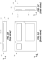
- FIGS. 1A, 1B and 1C are first used to describe an exemplary optical waveguide and its components, as well as its limitations. In the description that follows, like numerals or reference designators will be used to refer to like parts or elements throughout. In addition, the first digit of each reference number identifies the drawing in which the reference number first appears.
- FIGS. 1A, 1B and 1C are front, top and side views, respectively, of an exemplary optical waveguide 100 that can be used to replicate an image associated with an input-pupil to an expanded output-pupil.
- the term "input-pupil,” as used herein, refers to an aperture through which light corresponding to an image is overlaid on an input-coupler of a waveguide.
- An input-pupil is sometimes also referred to as an entrance-pupil
- an output-pupil is sometimes also referred to as an exit-pupil.
- the optical waveguide 100 will often be referred to hereafter more succinctly simply as a waveguide 100.
- the image that the waveguide 100 is being used to replicate, and likely also expand, can be generated using a display engine.
- the optical waveguide 100 includes a bulk-substrate 106 having an input-coupler 112 and an output-coupler 116.
- the input-coupler 112 is configured to couple light corresponding to an image associated with an input-pupil into the bulk-substrate 106 of the waveguide.
- the output-coupler 116 is configured to couple the light corresponding to the image associated with the input-pupil, which travels in the optical waveguide 100 from the input-coupler 112 to the output-coupler 116, out of the waveguide 100 so that the light is output and viewable from the output-pupil.
- the bulk-substrate 106 which can be made of glass or optical plastic, but is not limited thereto, includes a first major planar surface 108 and a second major planar surface 110 opposite and parallel to the first major planar surface 108.
- the first major planar surface 108 can alternatively be referred to as the front-side major surface 108 (or more simply the front-side surface 108), and the second major planar surface 110 can alternatively be referred to as the back-side major surface 110 (or more simply the back-side surface 110).
- a substrate is considered to be “bulk” substrate where the thickness of the substrate (between its major surfaces) is at least ten times (i.e., 10x) the wavelength of the light for which the substrate is being used as an optical transmission medium.
- the substrate will be considered a bulk-substrate where the thickness of the substrate (between its major surfaces) is at least 6200 nm, i.e., at least 6.2 ⁇ m.
- the bulk-substrate 106 has a thickness of at least 25 ⁇ m between its major planar surfaces 108 and 110.
- the bulk-substrate 106 has a thickness (between its major surfaces) within a range of 100 ⁇ m to 1500 ⁇ m, with a likely thickness of about 1000 ⁇ m.
- the bulk-substrate 106, and more generally the waveguide 100, is transparent, meaning that it allows light to pass through it so that a user can see through the waveguide 100 and observe objects on an opposite side of the waveguide 100 than the user's eye(s).
- the optical waveguide 100 in FIGS. 1A, 1B and 1C is also shown as including an intermediate-component 114, which can alternatively be referred to as an intermediate-zone 114.
- the input-coupler 112 is configured to couple light into the waveguide 100 (and more specifically, into the bulk-substrate 106 of the waveguide 100) and in a direction of the intermediate-component 114.
- the intermediate-component 114 is configured to redirect such light in a direction of the output-coupler 116.
- the intermediate-component 114 is configured to perform one of horizontal or vertical pupil expansion
- the output-coupler 116 is configured to perform the other one of horizontal or vertical pupil expansion.
- the intermediate-component 114 can be configured to perform horizontal pupil expansion, and the output-coupler 116 can be configured to vertical pupil expansion.
- the intermediate-component 114 were repositioned, e.g., to be below the input-coupler 112 and to the left of the output-coupler 116 shown in FIG. 1A , then the intermediate-component 114 can be configured to perform vertical pupil expansion, and the output-coupler 116 can be configured to perform horizontal pupil expansion.
- the input-coupler 112, the intermediate-component 114 and the output-coupler 116 can be referred to collectively herein as optical components 112, 114 and 116 of the waveguide, or more succinctly as components 112, 114 and 116.
- a waveguide includes an input-coupler and an output-coupler, without including an intermediate-component, not according to the invention as specified in claim 1.
- the input-coupler would be configured to couple light into the waveguide and in a direction toward the output-coupler.
- the output-coupler can provide one of horizontal or vertical pupil expansion, depending upon implementation.
- the input-coupler 112, the intermediate-component 114 and the output-coupler 116 are shown as having rectangular outer peripheral shapes, but can have alternative outer peripheral shapes.
- the input-coupler 112 can alternatively have a circular outer peripheral shape, but is not limited thereto.
- the intermediate-component can have a triangular or hexagonal outer peripheral shape, but is not limited thereto.
- the corners of each of the peripheral shapes e.g., where generally rectangular or triangular, can be chamfered or rounded, but are not limited thereto.
- the input-coupler 112, the intermediate-component 114 and the output-coupler 116 are all shown as being provided in or on a same surface (i.e., the back-side surface 110) of the waveguide 100.
- the input-coupler 112 can be transmissive (e.g., a transmission grating)
- the intermediate-component 114 can be reflective (e.g., a reflective grating)
- the output-coupler 116 can also be reflective (e.g., a further reflective grating).
- the input-coupler 112, the intermediate-component 114 and the output-coupler 116 can alternatively all be provided in the front-side surface 110 of the waveguide 100.
- the input-coupler 112 can be reflective (e.g., a reflective grating)
- the intermediate-component 114 can be reflective (e.g., a further reflective grating)
- the output-coupler 116 can also be transmissive (e.g., a transmission grating).
- the input-coupler 112, the intermediate-component 114 and the output-coupler 116 can all be embedded (also referred to as immersed) in the bulk-substrate 106.
- the bulk-substrate 106 can be separated into two halves (that are parallel to the major surfaces 108 and 110), and the input-coupler 112, the intermediate-component 114 and the output-coupler 116 can be provided in (e.g., etched into) one of the inner surfaces of the two halves, and the inner surfaces of the two halves can be adhered to one another.
- the bulk-substrate 106 can be separated into two halves (that are parallel to the major surfaces 108 and 110), and the input-coupler 112, the intermediate-component 114 and the output-coupler 116 can be provided between the inner surfaces of the two halves.
- Other implementations for embedding the input-coupler 112, the intermediate-component 114 and the output-coupler 116 in the bulk-substrate 106 are also possible, and within the scope of the embodiments described herein.
- one of the input-coupler 112, the intermediate-component 114 and the output-coupler 116 is provided in or on the front-side surface 108 of the waveguide 108, another one of the components 112, 114 and 116 is provided in or on the back-side surface 110, and the last one of the components 112, 114 and 116 is embedded or immersed in the bulk-substrate 106. More generally, unless stated otherwise, any individual one of the input-coupler 112, the intermediate-component 114 and the output-coupler 116 can be provided in or on either one of the major planar surfaces 108 or 110 of the bulk-substrate 106, or embedded therebetween.
- the input-coupler 112, the intermediate-component 114 and the output-coupler 116 are each implemented as a diffraction grating, or more generally, as a diffractive optical element (DOE).
- DOE diffractive optical element
- a diffraction grating is an optical component that may contain a periodic structure that causes incident light to split and change direction due to an optical phenomenon known as diffraction. The splitting (known as optical orders) and angle change depend on the characteristics of the diffraction grating.
- the periodic structure is on the surface of an optical component, it is referred to a surface grating.
- SRG surface relief grating
- an SRG can include uniform straight grooves in a surface of an optical component that are separated by uniform straight groove spacing regions. Groove spacing regions can be referred to as "lines", “grating lines” or “filling regions”. The nature of the diffraction by an SRG depends on the wavelength, polarization and angle of light incident on the SRG and various optical characteristics of the SRG, such as refractive index, line spacing, groove depth, groove profile, groove fill ratio and groove slant angle.
- An SRG can be fabricated by way of a suitable microfabrication process, which may involve etching of and/or deposition on a substrate to fabricate a desired periodic microstructure on the substrate to form an optical component, which may then be used as a production master such as a mold or mask for manufacturing further optical components.
- An SRG is an example of a Diffractive Optical Element (DOE).
- DOE Diffractive Optical Element
- a diffraction grating instead of being a surface grating, can alternatively be a volume grating, such as a Bragg diffraction grating.
- one or more of the couplers are manufactured as SRGs and then covered within another material, e.g., using an atomic layer deposition process or an aluminum deposition process, thereby essentially burying the SRGs such that the major planar waveguide surface(s) including the SRG(s) is/are substantially smooth.
- a coupler is one example of a hybrid of a surface and volume diffraction grating.
- Any one of the input-coupler 112, the intermediate-component 114 and the output-coupler 116 can be, e.g., a surface diffraction grating, or a volume diffraction grating, or a hybrid of a surface and volume diffraction grating.
- each diffraction grating can have a preferential linear polarization orientation specified by a direction of the grating lines of the diffraction grating, wherein the coupling efficiency for light having the preferential linear polarization orientation will be higher than for light having a non-preferential linear polarization orientation.
- each such SRG can be etched into one of the major planar surfaces 108 or 110 of the bulk-substrate 106.
- the SRG can be said to be formed "in” the bulk-substrate 106.
- each SRG can be physically formed in a coating that covers one of the major planar surfaces 108 or 110 of the bulk-substrate 106, in which case each such SRG can be said to be formed "on" the bulk-substrate 106.
- the components 112, 114 and 116 are considered parts of the waveguide 100.
- the input-coupler 112 can have surface gratings that extend in a vertical (y) direction
- the output-coupler 116 can have surface gratings that extend in a horizontal (x) direction
- the intermediate-component 114 can have surface gratings that extend diagonal (e.g., -45 degrees) relative to the horizontal and vertical directions. This is just an example. Other variations are also possible.
- the input-coupler 112, the intermediate-component 114 and the output-coupler 116 can have various different outer peripheral geometries, can be provided in or on either of the major planar surfaces of the bulk-substrate, or can be embedded in the bulk-substrate 106, and can be implemented using various different types of optical structures, as can be appreciated from the above discussion, and will further be appreciated from the discussion below.
- TIR total internal refection
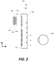
- FIG. 2 shows a side view of the waveguide 100, but also shows a display engine 204 that generates an image including angular content that is coupled into the waveguide by the input-coupler 112. Also shown in FIG. 2 , is representation of a human eye 214 that is using the waveguide 100 to observe an image, produced using the display engine 204, as a virtual image.
- the display engine 204 can include, e.g., an image former 206, a collimating lens 208 and an illuminator 210, but is not limited thereto.
- the image former 206 can be implemented using a transmissive projection technology where a light source is modulated by an optically active material, and backlit with white light. These technologies are usually implemented using liquid crystal display (LCD) type displays with powerful backlights and high optical energy densities.
- the illuminator 210 can provide the aforementioned backlighting.
- the image former 206 can also be implemented using a reflective technology for which external light is reflected and modulated by an optically active material. Digital light processing (DLP), liquid crystal on silicon (LCOS) and Mirasol ® display technology from Qualcomm, Inc.
- DLP digital light processing
- LCOS liquid crystal on silicon
- Mirasol ® display technology from Qualcomm, Inc.
- the image former 206 can be implemented using an emissive technology where light is generated by a display, see for example, a PicoP TM display engine from Microvision, Inc. Another example of emissive display technology is a micro organic light emitting diode (OLED) display. Companies such as eMagin and Microoled provide examples of micro OLED displays.
- the image former 206 alone or in combination with the illuminator 210, can also be referred to as a micro display.
- the collimating lens 208 is arranged to receive a diverging display image from the image former 206, to collimate the display image, and to direct the collimated image toward the input-coupler 112 of the waveguide 100.
- an entry pupil associated with the waveguide may be approximately the same size as an exit pupil associated with the image former 206, e.g., 5 mm or less in some embodiments, but is not limited thereto.
- the display engine 204 is shown as facing the back-side surface 110 of the waveguide 100, and the eye 214 is shown as facing the front-side surface 108 opposite and parallel to the back-side surface 110.
- This provides for a periscope type of configuration in which light enters the waveguide on one side of the waveguide 100, and exits the waveguide at an opposite side of the waveguide 100.
- the input-coupler 112 and the output-coupler 116 can be implemented in a manner such that the display engine 204 and the eye 214 are proximate to and face a same major planar surface (108 or 110).
- the waveguide 100 can be incorporated into a see-through mixed reality display device system, but is not limited to use therewith.
- a separate instance of the waveguide 100 and the display engine 204 can be provided for each of the left and right eyes of a user.
- such waveguide(s) 100 may be positioned next to or between see-through lenses, which may be standard lenses used in eye glasses and can be made to any prescription (including no prescription).
- a see-through mixed reality display device system is implemented as head-mounted display (HMD) glasses including a frame
- the display engine 204 can be located to the side of the frame so that it sits near to a user's temple.
- the display engine 204 can be located in a central portion of the HMD glasses that rests above a nose bridge of a user. Other locations for the display engine 204 are also possible. In these instances, the user can also be referred to as a wearer. Where there is a separate waveguide for each of the left and right eyes of a user, there can be a separate display engine for each of the waveguides, and thus, for each of the left and right eyes of the user. One or more further adjacent waveguides can be used to perform eye tracking based on infrared light that is incident on and reflected from the user's eye(s) 214, as is known in the art.
- the exemplary optical waveguide 100 can support a diagonal field-of-view (FOV) of only about 35 degrees, where the index of refraction of the bulk-substrate 106 is about 1.7 (i.e., n1 ⁇ 1.7).
- the optical component that limits the diagonal FOV to about 35 degrees is the intermediate-component 112, since the input-coupler 112 and the output-coupler 116 can each handle much larger diagonal FOVs than the intermediate-component 112.
- One way to attempt to increase (also referred to as extend) the diagonal FOV is to increase the index of refraction of the bulk-substrate 106 of the optical waveguide 100, which would enable the intermediate-component 112 to support a larger diagonal FOV.
- materials e.g., glass
- suitable materials for producing bulk-substrates having such a high index of refraction in large quantities are not readily available. Accordingly, literature about waveguide based displays that include intermediate-components, for use in pupil expansion, typically specify that the upper limit for the diagonal FOV is about 35 degrees.
- an optical waveguide includes at least two intermediate-components, each of which is used to support a different part of a FOV.
- the input-coupler is designed to diffract light in at least two different (e.g., opposite) directions in order to guide light corresponding to an image to different intermediate-components. For example, by appropriately tuning the grating periods of the input-coupler, light corresponding to a left portion of a FOV is steered to a left intermediate-component, and light corresponding to a right portion of the FOV is steered to a right intermediate-component.
- grating periods can be appropriately tuned so that part of the FOV (e.g., a central portion of the FOV) that is not to be steered to either of the left and right intermediate-components goes to an evanescent diffraction order that does not carry any power.
- part of the FOV e.g., a central portion of the FOV
- different parts of a FOV can be guided in different directions.
- Such embodiments can provide two significant advantages. First, such embodiments can provide for a total diagonal FOV that is very large, even though each of the intermediate-components individually support a relatively smaller FOV (e.g., a diagonal FOV of no more than about 35 degrees).
- FIG. 3 is a front view of an optical waveguide 300, according to an embodiment of the present technology.
- the optical waveguide 300 is shown as including an input-coupler 312, two intermediate-components 314a and 314b, and an output-coupler 316.
- the input-coupler 312 includes a diffraction grating and is configured to couple light corresponding to an image associated with an input-pupil, and having a corresponding FOV, into the optical waveguide 300 (and more specifically into the bulk-substrate of the optical waveguide).
- the input-coupler 312 is also configured to diffract a portion of the light corresponding to the image in a first direction toward the first intermediate-component 314a such that a first portion of the FOV travels through the optical waveguide 300 from the input-coupler 312 to the first intermediate-component 314a, and diffract a portion of the light corresponding to the image in a second direction toward the second intermediate-component 314b such that a second portion of the FOV travels through the optical waveguide 300 from the input-coupler 312 to the second intermediate-component 314b.
- the first and second portions of the FOV differ from one another, and depending upon implementation, may (or may not) partially overlap one another.
- the first and second directions, in which the input-coupler 212 diffracts light, also differ from one another.
- the first direction is a leftward direction
- the second direction is a rightward direction. More specifically, the first direction is both leftward and acutely angled downward, and the second direction is both rightward and acutely angled downward.
- the intermediate-component 314a is configured to perform horizontal pupil expansion, and to diffract light corresponding to the first portion of the FOV, which travels through the optical waveguide from the input-coupler 312 to the first intermediate-component 314a, toward the output coupler 316.
- the intermediate-component 314b is configured to perform horizontal pupil expansion, and to diffract light corresponding to the second portion of the FOV, which travels through the optical waveguide from the input-coupler 312 to the second intermediate-component 314b, toward the output coupler 316.
- the intermediate-components 314a and 314b can individually be referred to as an intermediate-component 314, or collectively as intermediate-components 314.
- the layout and optical components can be rearranged and reconfigured (e.g., by rotating the layout by 90 degrees) such that the intermediate-components 314 are configured to perform vertical pupil expansion, and the output-coupler 316 is configured to perform horizontal pupil expansion. More generally, the intermediate-components can be configured to perform one of horizontal or vertical pupil expansion, and the output-coupler can be configured to perform the other one of horizontal or vertical pupil expansion.
- the output-coupler 316 is configured to combine the light corresponding to the first and second portions of the FOV, which travel through the optical waveguide from the first and second intermediate-components 314a and 314b to the output-coupler 316.
- the output-coupler 316 is also configured to couple the light corresponding to the combined first and second portions of the FOV out of the optical waveguide 300 so that the light corresponding to the image and the combined first and second portions of the FOV is output from the optical waveguide 300 and viewable from an output-pupil.
- the input-coupler 312, the intermediate-component 314 and the output-coupler 316 can be referred to collectively herein as optical components 312, 314 and 316 of the waveguide, or more succinctly as components 312, 314 and 316.
- the waveguides e.g., 100 and 300
- surfaces of a waveguide e.g., 100, 300, 400, 500 or 600
- gratings may be more easily manufacture on or in planar surfaces, with curved surface(s) it could be possible to reduce some of the aberrations in a system.
- the intermediate-component typically limits the diagonal FOV of waveguide based displays to no more than 35 degrees.
- intermediate-component(s) can typically only support a FOV up to about 35 degrees.
- the input-coupler and the output-coupler of an optical waveguide are each able to support a much larger FOV than an individual intermediate-component.
- the input-coupler and the output-coupler of an optical waveguide can each support a FOV that is at least twice as large as an intermediate component.
- the intermediate-component is typically the optical component of an optical waveguide that limits the total FOV that can be achieved using the optical waveguide.
- the input-coupler 312 by diffracting a portion of the light corresponding to the image in the first direction toward the first intermediate-component 314a, and diffracting a portion of the light corresponding to the image in the second direction toward the second intermediate-component 314b, splits the FOV into the first and second portions.
- the output-coupler 316 by combining the light corresponding to the first and second portions of the FOV, unifies the FOV that was split by the input-coupler 312.
- the FOV associated with the light coupled out of the optical waveguide 300, by the output-coupler 312 is greater than a maximum FOV that each of the first and second intermediate-components 314 can support on their own.
- the input-coupler 312 can split the 70 degree FOV into a first 35 degree FOV portion (which travel by way of TIR to the first intermediate-component 314a) and a second 35 degree FOV portion (which travel by way of TIR to the second intermediate-component 314b).
- the first portion of the FOV can be from 0 to 35 degrees
- the second portion of the FOV can be from 35 to 70 degrees.
- the output-coupler 316 can then combine the light corresponding to the first 35 degree portion of the FOV (which travel through the optical waveguide by way of TIR from the first intermediate-component 314a to the output-coupler 316) and the light corresponding to the second 35 degree FOV (which travel through the optical waveguide by way of TIR from the second intermediate-components 314b to the output-coupler 316), to thereby unify the two 35 degree FOV portions into the original FOV of about 70 degrees.
- the output-coupler 316 couples the light corresponding to the combined first and second portions of the FOV, i.e., combined to have the FOV of about 70 degrees, out of the optical waveguide 300 so that the light corresponding to the image and the combined first and second portions of the FOV is output from the optical waveguide 300 and viewable from an output-pupil. Accordingly, the about 70 degree FOV associated with the light coupled out of the optical waveguide 300, by the output-coupler 312, is greater than the about 35 degree FOV that each of the first and second intermediate-components 314a and 314b can support on their own.
- first and second portions of the FOV differ from one another, and depending upon implementation, may (or may not) partially overlap one another. Accordingly, where first and second portions of the FOV partially overlap one another, the first portion of the FOV may be, e.g., from 2 to 37 degrees, and the second portion of the FOV may be from 33 to 68 degrees. This is just one example, which is not intended to be limiting.
- the input-coupler 312, the intermediate-components 314 and the output-coupler 316 can each be implemented as a DOE.
- the input-coupler 312, the intermediate-components 314 and the output-coupler 316 are implemented as SRG type DOEs that are in or on one (or both) of the major surfaces of the waveguide 300.
- each of the SRGs can include uniform straight grooves in or on only one of the major surfaces of the waveguide 300, which grooves are separated by uniform straight groove spacing regions. The nature of the diffraction by each SRG depends both on the wavelength of light incident on the grating and various optical characteristics of the SRG, such as line spacing, groove depth and groove slant angle.
- Each SRG can be fabricated by way of a suitable microfabrication process, which may involve etching of and/or deposition on a substrate to fabricate a desired periodic microstructure in or on the substrate to form an optical component, which may then be used as a production master such as a mold or mask for manufacturing further optical components.
- the input-coupler 312 is implemented as an SRG in or one only one of the major surfaces of the waveguide 300, wherein the line spacing of the gratings of the input-coupler 312 is constant, but the slant angle of a first half the gratings is optimized to direct a portion of the light incident on the input-coupler 312 in the direction of the first intermediate-component 314a, and the slant angle of a second half the gratings is optimized to direct a portion of the light incident on the input-coupler 312 in the direction of the second intermediate-component 314b.
- the input-coupler 312 is implemented as an SRG in or one both of the major surfaces of the waveguide 300.
- a first SRG is located in or on one the major surfaces of the optical waveguide 300 and is configured to diffract the light corresponding to a first portion of the FOV in a first direction toward the first intermediate-component 314a
- a second SRG is located in or on the other one of the major surfaces of the optical waveguide 300 and is configured to diffract the light corresponding to a second portion of the FOV in a second direction toward the second intermediate-component 314b.
- the grating period of the first SRG of the input-coupler 312 is the same as the grating period of the second SRG of the input-coupler 312, but the slant angles differ from one another. In accordance with another embodiment, the grating period of the first SRG of the input-coupler 312 differs from the grating period of the second SRG of the input-coupler 312.
- FIG. 3 illustrates just one exemplary layout for the input-coupler, intermediate-components and output-coupler.
- FIG. 4 illustrates an alternative layout for the input-coupler, intermediate-components and output-coupler.
- an input-coupler 412 includes a diffraction grating and is configured to couple light corresponding to an image associated with an input-pupil, and having a corresponding FOV, into the optical waveguide 400, diffract a portion of the light corresponding to the image in a first direction toward a first intermediate-component 414a such that a first portion of the FOV travels through the optical waveguide 400 from the input-coupler 412 to the first intermediate-component 414a, and diffract a portion of the light corresponding to the image in a second direction toward a second intermediate-component 414b such that a second portion of the FOV travels through the optical waveguide 400 from the input-coupler 412 to the second intermediate-component 414b.
- the first direction is a leftward direction
- the second direction is a rightward direction.
- An output-coupler 416 is configured to combine the light corresponding to the first and second portions of the FOV, which travel through the optical waveguide from the first and second intermediate-components 414a and 414b to the output-coupler 416.
- the output-coupler 416 is also configured to couple the light corresponding to the combined first and second portions of the FOV out of the optical waveguide 400 so that the light corresponding to the image and the combined first and second portions of the FOV is output from the optical waveguide 400 and viewable from an output-pupil.
- the optical waveguide includes one or more further intermediate-components, which is/are in addition to the first and second intermediate-components, and the input-coupler is also configured to diffract light corresponding to at least a portion of the FOV to each of the one or more further intermediate-components.
- the one or more further intermediate-components is/are each configured to diffract light, corresponding to at least a portion of the FOV that is incident on the further intermediate-component, toward the output-coupler of the optical waveguide. Examples of such embodiments are shown in FIGS. 5 and 6 .
- an optical waveguide 500 is shown as including an input-coupler 512, four intermediate-components 514a, 514b, 514c and 514d, and an output-coupler 516.
- the input-coupler 512 includes one or more diffraction gratings and is configured to couple light corresponding to an image associated with an input-pupil, and having a corresponding FOV, into the optical waveguide 500.
- the input-coupler 514a is also configured to diffract a portion of the light corresponding to the image in a first direction toward the intermediate-component 514a such that a first portion of the FOV travels through the optical waveguide 500 from the input-coupler 512 to the intermediate-component 514a, diffract a portion of the light corresponding to the image in a second direction toward the intermediate-component 414b such that a second portion of the FOV travels through the optical waveguide 500 from the input-coupler 512 to the intermediate-component 514b, diffract a portion of the light corresponding to the image in a third direction toward the intermediate-component 514c such that a third portion of the FOV travels through the optical waveguide 500 from the input-coupler 512 to the intermediate-component 514c, and diffract a portion of the light corresponding to the image in a fourth direction toward the fourth intermediate-component 514d such that a fourth portion of the FOV travels through the optical waveguide 500 from the
- the portion of the FOV provided to the intermediate-component 514a differs from the portion of the FOV provided to the intermediate-component 514d
- the portion of the FOV provided to the intermediate-component 514b differs from the portion of the FOV provided to the intermediate-component 514c.
- the portion of the FOV provided to the intermediate-component 514b may be the same or different that the portion of the FOV provided to the intermediate component 514a
- the portion of the FOV provided to the intermediate-component 514c may be the same or different that the portion of the FOV provided to the intermediate component 514d.
- the grating period of the input-coupler 512 is tuned so that part of the FOV that is not to be steered to either of the intermediate-components 514a and 514d goes to an evanescent diffraction order that does not carry any power.
- each of the intermediate components 514a and 514d is configured to perform horizontal pupil expansion, and diffract light having a respective portion of the original FOV toward the output-coupler 516.
- the intermediate components 514b and 514c can also be configured to perform horizontal pupil expansion, and diffract light having a respective portion of the original FOV toward the output-coupler 516.
- the intermediate components 514b and 514c can diffract light having a respective portion of the original FOV toward the output-coupler 516 without performing any pupil expansion, in which case the middle portion of the output-coupler 516 can output light corresponding to the image having a FOV coming straight from the input-coupler 512.
- the output-coupler 516 is also configured to combine the FOVs and couple the light corresponding to the combined FOVs out of the optical waveguide 500 so that the light corresponding to the image and the combined FOVs is output from the optical waveguide 500 and viewable from an output-pupil.
- an optical waveguide 600 is shown as including an input-coupler 612, three intermediate-components 614a, 614b and 614c, and an output-coupler 616.
- the input-coupler 612 includes one or more diffraction gratings and is configured to couple light corresponding to an image associated with an input-pupil, and having a corresponding FOV, into the optical waveguide 600.
- the input-coupler 614a is also configured to diffract a portion of the light corresponding to the image in a first direction toward the first intermediate-component 614a such that a first portion of the FOV travels through the optical waveguide 600 from the input-coupler 612 to the first intermediate-component 614a, diffract a portion of the light corresponding to the image in a second direction toward the second intermediate-component 614b such that a second portion of the FOV travels through the optical waveguide 600 from the input-coupler 612 to the second intermediate-component 614b, and diffract a portion of the light corresponding to the image in a third direction toward the third intermediate-component 614c such that a third portion of the FOV travels through the optical waveguide 600 from the input-coupler 612 to the third intermediate-component 614c.
- the portion of the FOV provided to the intermediate-component 614a differs from the portion of the FOV provided to the intermediate-component 614c.
- the portion of the FOV provided to the intermediate-component 514b can include part of the FOV provided to the intermediate-component 614a and part of the FOV provided to the intermediate-component 614c.
- the portion of the FOV provided to the intermediate-component 514b can alternatively be distinct from the portion of the FOV provided to the intermediate-component 614a and portion of the FOV provided to the intermediate-component 614c.
- the grating period of the input-coupler 612 is tuned so that part of the FOV that is not to be steered to either of the intermediate-components 614a and 614c goes to an evanescent diffraction order that does not carry any power.
- each of the intermediate components 614a and 614c is configured to perform horizontal pupil expansion, and diffract light having a respective portion of the original FOV toward the output-coupler 616.
- the intermediate component 614b can also be configured to perform horizontal pupil expansion, and diffract light having a respective portion of the original FOV toward the output-coupler 616.
- the intermediate components 614b can diffract light having a respective portion of the original FOV toward the output-coupler 616 without performing any pupil expansion, in which case the middle portion of the output-coupler 616 can output light corresponding to the image having a FOV coming straight from the input-coupler 612.
- the output-coupler 616 is also configured to combine the FOVs and couple the light corresponding to the combined FOVs out of the optical waveguide 600 so that the light corresponding to the image and the combined FOVs is output from the optical waveguide 600 and viewable from an output-pupil.
- each of the optical waveguides is for use with a display engine, which can be the same as or similar to the display engine 204 described above with reference to FIG. 2 , but is not limited thereto.
- the display engine e.g., 204
- a user's eye e.g., the eye of a person wearing HMD glasses
- the input-coupler and the output-coupler can be implemented in a manner such that the display engine and a user's eye are proximate to and face a same major surface of the optical waveguide.
- optical waveguides are used to perform pupil replication (also referred to as image replication)
- pupil replication also referred to as image replication
- non-uniformities in local and global intensities may occur, which may result in dark and light fringes and dark blotches when the replicated image is viewed, which is undesirable.
- the embodiments shown in and described with reference to FIGS. 5 and 6 may provide for improved intensity distributions, and thereby, can be used to improve the replicated image when viewed, compared to the embodiments shown in and described with reference to FIGS. 3 and 4 .
- each of the diffraction gratings instead of being a surface grating, can alternatively be a volume grating, such as a Bragg diffraction grating.
- one or more of the couplers are manufactured as SRGs and then covered within another material, e.g., using an aluminium deposition process, thereby essentially burying the SRGs such that the major planar waveguide surface(s) including the SRG(s) is/are substantially smooth.
- Such a coupler is one example of a hybrid of a surface and volume diffraction grating.
- any one of the input-coupler (e.g., 312, 412, 512, 612), the intermediate-components (e.g., 314, 414, 514, 614) and the output-coupler (e.g., 316, 416, 516, 616) can be, e.g., a surface diffraction grating, or a volume diffraction grating, or a hybrid of a surface and volume diffraction grating.
- each diffraction grating can have a preferential linear polarization orientation specified by a direction of the grating lines of the diffraction grating, wherein the coupling efficiency for light having the preferential linear polarization orientation will be higher than for light having a non-preferential linear polarization orientation.
- a large FOV of at least 70 degrees, and potentially up to 90 degrees or even larger can be achieved by an optical waveguide that utilizes intermediate-components to provide pupil expansion, even where the intermediate-components individually can only support of FOV of about 35 degrees. Additionally, where only a portion of the total FOV is guided to disparate intermediate-components, a power savings of up to 50% can be achieved when compared to a situation where the FOV is not split by the input-coupler.
- the input-coupler of an optical waveguide is located near the temple or nose bridge region of a wearer, when the HMD is being worn. This may be the case with the embodiments described above with reference to FIGS. 1 and 2 .
- the input-coupler may be directly above the eye of the wearer of an HMD, resulting in a shorter the propagation distance that light corresponding to the image travels between the input-coupler and the output-coupler, before the light is output and viewed by the eye of the wearer. This shorter distance results in a lower cumulative error.
- a portion e.g., a middle portion
- a combination of two-dimensional and one-dimensional pupil expansion can be supported by a single optical waveguide.
- the optical waveguides (e.g., 300, 400, 500, 600) described herein can be incorporated into a see-through mixed reality display device system.
- the same waveguide can be used to steer light of multiple different colors (e.g., red, green and blue) associated with an image from the input-coupler to the output-coupler.
- three waveguides can be stacked adjacent to each other, with each of the waveguides being used to steer light of a different color (e.g., red, green or blue) associated with an image from its respective input-coupler to its output-coupler.
- one waveguide handle light of two colors (e.g., green and blue) and another waveguide handles light of a third color (e.g., red).
- Other variations are also possible.
- the optical waveguides (e.g., 300, 400, 500 or 600) described herein are for use in steering light from an input-coupler to an output-coupler, where the light is out-coupled for viewing or imaging by one of a person's two eyes (i.e., either their left or right eye).
- One or more further instances of the waveguide e.g., 300, 400, 500 or 600
- the other eye i.e., either their left or right eye.
- a separate instance of the waveguide (e.g., 300, 400, 500 or 600) and the display engine 204 can be provided for each of the left and right eyes of a user.
- such waveguide(s) may be positioned next to or between see-through lenses, which may be standard lenses used in eye glasses and can be made to any prescription (including no prescription).
- see-through lenses which may be standard lenses used in eye glasses and can be made to any prescription (including no prescription).
- there is a separate waveguide for each of the left and right eyes of a user there can be a separate display engine for each of the waveguides, and thus, for each of the left and right eyes of the user.
- One or more further adjacent waveguides can be used to perform eye tracking based on infrared light that is incident on and reflected from the user's eye(s) 214, as is known in the art.
- the input-couplers, the intermediate-components and the output-couplers were are shown as having specific outer peripheral shapes, but can have alternative outer peripheral shapes. Similarly, the peripheral shape of the optical waveguides can also be changed, while still being within the scope of embodiments described herein.
- the input-coupler e.g., 312, 412, 512, 612
- the output-coupler e.g., 316, 416, 516, 616
- certain intermediate-components e.g., 314a, 414a, 514a, 614a
- other intermediate-components e.g., 314b, 414b, 514d, 614c
- the grating periods of the intermediate-components of an optical waveguide can all be the same, or can all be different. Regardless, two or more of the intermediate-components of an optical waveguide should perform pupil expansion and steer light toward the output-coupler of the optical waveguide.
- step 702 involves coupling light corresponding to the image associated with the input-pupil, and having a corresponding FOV, into the optical waveguide.
- Step 704 involves splitting the FOV of the image coupled into the optical waveguide into first and second portions by diffracting a portion of the light corresponding to the image in a first direction, and diffracting a portion of the light corresponding to the image in a second direction, wherein the first and second directions differ from one another, and wherein the first and second portions of the FOV differ from one another.
- one of the first and second directions comprises a leftward direction
- the other one of the first and second directions comprises a rightward direction.
- Step 706 involves, after the light corresponding to the image has travelled through portions of the optical waveguide by way of total internal reflection (TIR) (e.g., from an input-coupler to a spatially separated output-coupler), combining the light corresponding to the first and second portions of the FOV, and coupling the light corresponding to the combined first and second portions of the FOV out of the optical waveguide so that the light corresponding to the image and the combined first and second portions of the FOV is output from the optical waveguide and viewable from the output-pupil.
- TIR total internal reflection
- steps 702 and 704 can be performed by an input-coupler (e.g., 312, 412, 512 or 612) of the optical waveguide, and step 706 can be performed by an output-coupler (e.g., 316, 416, 516 or 616) of the optical waveguide.
- an input-coupler e.g., 312, 412, 512 or 612
- step 706 can be performed by an output-coupler (e.g., 316, 416, 516 or 616) of the optical waveguide.
- the light corresponding to the first and second portions of the FOV is transferred from the input-coupler, respectively, to first and second intermediate-components of the optical waveguide by way of total internal reflection (TIR), and the first and second intermediate-components of the optical waveguide are used to perform one of horizontal or vertical pupil expansion.
- TIR total internal reflection
- the output-coupler of the optical-waveguide is used to perform the other one of horizontal or vertical pupil expansion.
- the input-coupler by diffracting a portion of the light corresponding to the image in the first direction toward a first intermediate-component, and diffracting a portion of the light corresponding to the image in the second direction toward the second intermediate-component, splits the FOV into the first and second portions.
- the output-coupler by combining the light corresponding to the first and second portions of the FOV, unifies the FOV that was split by the input-coupler.
- a unified FOV associated with the light coupled out of the optical waveguide, by the output-coupler is greater than a maximum FOV that each of the first and second intermediate-components can support on their own, as was explained above.
- a FOV associated with light corresponding to an image that is coupled into a waveguide by an input-coupler can be split into more than two portions, and the more than two portions of the FOV can be combined by the output-coupler of the waveguide.
- Embodiments described herein can be used to increase (also referred to as extend) the FOV that can be supported by an optical waveguide, without requiring that image tiling be used, which has been proposed. Further, embodiments described herein can be used to increase the FOV that can be supported by an optical waveguide, without requiring the use of switchable Bragg gratings. Nevertheless, it is possible that one or more of the input-coupler, intermediate-components and output-coupler, in the embodiments described with reference to FIGS. 3-6 , can be implemented using a switchable Bragg grating.
- the grating is switchable that enables the optical waveguide to support a large FOV, as was the case in other proposals that rely only switching and time division multiplexing of different portions of an image and/or different grating prescriptions to support a large FOV.
Landscapes
- Physics & Mathematics (AREA)
- General Physics & Mathematics (AREA)
- Optics & Photonics (AREA)
- Nonlinear Science (AREA)
- Engineering & Computer Science (AREA)
- Multimedia (AREA)
- Signal Processing (AREA)
- Optical Couplings Of Light Guides (AREA)
Claims (15)
- Appareil pour l'utilisation dans la réplication d'une image associée à une pupille d'entrée dans une pupille de sortie, l'appareil comprenant :un guide d'onde optique (300, 400, 500, 600) incluant un coupleur d'entrée (312, 412, 512, 612), des premier et second composants intermédiaires (314a, 314b, 414a, 414b, 514a, 514b, 614a, 614b) et un coupleur de sortie (316, 416, 516, 616) ;le coupleur d'entrée (312, 412, 512, 612) comprenant un réseau de diffraction et dans lequel le réseau de diffraction est configuré pourcoupler la lumière correspondant à l'image associée à la pupille d'entrée, et présentant un champ de vision (FOV) correspondant, dans le guide d'onde optique ;diffracter une portion de la lumière correspondant à l'image dans une première direction vers le premier composant intermédiaire de sorte qu'une première portion du FOV se déplace à travers le guide d'onde optique depuis le coupleur d'entrée au premier composant intermédiaire ; etdiffracter une portion de la lumière correspondant à l'image dans une seconde direction vers le second composant intermédiaire de sorte qu'une seconde portion du FOV se déplace à travers le guide d'onde optique depuis le coupleur d'entrée au second composant intermédiaire ;dans lequel les première et seconde directions diffèrent l'une de l'autre ; etdans lequel les première et seconde portions du FOV diffèrent l'une de l'autre ;le premier composant intermédiaire (314a, 414a, 514a, 614a) étant configuré pour diffracter de la lumière correspondant à la première portion du FOV, qui se déplace à travers le guide d'onde optique depuis le coupleur d'entrée au premier composant intermédiaire, vers le coupleur de sortie ;le second composant intermédiaire (314b, 414b, 514b, 614b) étant configuré pour diffracter de la lumière correspondant à la seconde portion du FOV, qui se déplace à travers le guide d'onde optique depuis le coupleur d'entrée au second composant intermédiaire, vers le coupleur de sortie ; etle coupleur de sortie (316, 416, 516, 616) comprenant un seul réseau de diffraction, et dans lequel le seul réseau de diffraction est configuré pour :combiner la lumière correspondant aux première et seconde portions du FOV, lesquelles se déplacent à travers le guide d'onde optique depuis les premier et second composants intermédiaires au coupleur de sortie ; etcoupler la lumière correspondant aux première et seconde portions combinées du FOV hors du guide d'onde optique de sorte que la lumière correspondant à l'image et aux première et seconde portions du FOV combinées soit sortie du guide d'onde optique et visible par une seule pupille de sortie.
- Appareil selon la revendication 1, dans lequel :le coupleur d'entrée, par diffraction de la portion de la lumière correspondant à l'image dans la première direction vers le premier composant intermédiaire, et diffraction de la portion de la lumière correspondant à l'image dans la seconde direction vers le second composant intermédiaire, divise le FOV en première et seconde portions ;le coupleur de sortie, par combinaison de la lumière correspondant aux première et seconde portions du FOV, unifie le FOV qui a été divisé par le coupleur d'entrée ; etun FOV unifié associé à la lumière couplée hors du guide d'onde optique, par le coupleur de sortie, est supérieur à un FOV maximum que chacun des premier et second composants intermédiaires peut supporter seuls.
- Appareil selon la revendication 1, dans lequel :chacun des premier et second composants intermédiaires est configuré pour réaliser une de la dilatation de pupille horizontale ou verticale ; etle coupleur de sortie est configuré pour réaliser l'autre de la dilatation de pupille horizontale ou verticale.
- Appareil selon la revendication 1, dans lequel :
une des première et seconde directions comprend une direction vers la gauche ; et l'autre des première et seconde directions comprend une direction vers la droite. - Appareil selon la revendication 1, dans lequel la première portion du FOV recouvre partiellement la seconde portion du FOV.
- Appareil selon l'une quelconque des revendications 1-5, dans lequel :le guide d'onde optique inclut une première surface majeure et une seconde surface majeure opposée à la première surface majeure ; etle réseau de diffraction du coupleur d'entrée comprend un réseau en relief de surface (SRG) qui est situé dans ou sur une seule des première et seconde surfaces majeures du guide d'onde optique.
- Appareil selon l'une quelconque des revendications 1-5, dans lequel :le guide d'onde optique inclut une première surface majeure et une seconde surface majeure opposée à la première surface majeure ; etle réseau de diffraction du coupleur d'entrée comprendun premier réseau en relief de surface (SRG) qui est situé dans ou sur une des première et seconde surfaces majeures du guide d'onde optique et est configuré pour diffracter la lumière correspondant à la première portion du FOV dans la première direction vers le premier composant intermédiaire, etun second SRG qui est situé dans ou sur l'autre des première et seconde surfaces majeures du guide d'onde optique et est configuré pour diffracter la lumière correspondant à la seconde portion du FOV dans la seconde direction vers le second composant intermédiaire.
- Appareil selon l'une quelconque des revendications 1-5, comprenant en outre un ou plusieurs autres composants intermédiaires qui est/sont en plus des premier et second composants intermédiaires, dans lequel :le coupleur d'entrée est aussi configuré pour diffracter de la lumière correspondant à au moins une portion du FOV sur chacun des un ou plusieurs autres composants intermédiaires ; etles un ou plusieurs autres composants intermédiaires est/sont chacun configurés pour diffracter de la lumière, correspondant à au moins une portion du FOV qui est incident sur l'autre composant intermédiaire, vers le coupleur de sortie.
- Appareil selon l'une quelconque des revendications 1 à 5, comprenant en outre :un moteur d'affichage configuré pour produire une image ;dans lequel la lumière correspondant à l'image qui est couplée dans le guide d'onde optique par le coupleur d'entrée comprend la lumière correspondant à l'image qui est produite par le moteur d'affichage.
- Appareil selon l'une quelconque des revendications 1-5, dans lequel chacun du coupleur d'entrée, des premier et second composants intermédiaires et du coupleur de sortie comprend un élément optique diffractif séparé (DOE).
- Appareil selon l'une quelconque des revendications 1-5, dans lequel l'appareil fait partie d'un affichage monté sur la tête (HMD) ou d'un affichage tête haute (HUD).
- Procédé d'utilisation d'un guide d'onde optique pour répliquer une image associée à une pupille d'entrée dans une pupille de sortie, le procédé comprenant :le couplage de la lumière correspondant à l'image associée à la pupille d'entrée, et présentant un champ de vision (FOV) correspondant, dans le guide d'onde optique utilisant un réseau de diffraction ;la division, en utilisant le réseau de diffraction, du FOV de l'image couplée dans le guide d'onde optique en première et seconde portions par diffraction d'une portion de la lumière correspondant à l'image dans une première direction, et diffraction d'une portion de la lumière correspondant à l'image dans une seconde direction, dans lequel les première et seconde directions diffèrent l'une de l'autre, et dans lequel les première et seconde portions du FOV diffèrent l'une de l'autre ; etaprès que la lumière correspondant à l'image s'est déplacée à travers des portions du guide d'onde optique à l'aide de la réflexion interne totale, la combinaison en utilisant un seul réseau de diffraction de la lumière correspondant aux première et seconde portions du FOV, et le couplage de la lumière correspondant aux première et seconde portions combinées du FOV hors du guide d'onde optique de sorte que la lumière correspondant à l'image et aux première et seconde portions combinées du FOV soit sortie du guide d'onde optique et visible d'une seule pupille de sortie.
- Procédé selon la revendication 12, dans lequel :
une des première et seconde directions comprend une direction vers la gauche ; et l'autre des première et seconde directions comprend une direction vers la droite. - Procédé selon la revendication 12 ou 13, dans lequel :le couplage de la lumière correspondant à l'image associée à la pupille d'entrée, et présentant le FOV correspondant, dans le guide d'onde optique, et la division du FOV de l'image couplée dans le guide d'onde optique en première et seconde portions, par diffraction de la portion de la lumière correspondant à l'image dans la première direction, et diffraction de la portion de la lumière correspondant à l'image dans la seconde direction, sont réalisés par un coupleur d'entrée du guide d'onde optique ;avant la combinaison de la lumière correspondant aux première et seconde portions du FOV pour unifier ainsi le FOV qui a été divisé, le transfert de la lumière correspondant aux première et seconde portions du FOV depuis le coupleur d'entrée, respectivement, aux premier et second composants intermédiaires du guide d'onde optique à l'aide de la réflexion interne totale (TIR), et l'utilisation des premier et second composants intermédiaires du guide d'onde optique pour réaliser une de la dilatation de pupille horizontale ou verticale ; etla combinaison de la lumière correspondant aux première et seconde portions du FOV, et le couplage de la lumière correspondant aux première et seconde portions combinées du FOV hors du guide d'onde optique, sont réalisés par un coupleur de sortie du guide d'onde optique.
- Procédé selon la revendication 14, comprenant en outre l'utilisation du coupleur de sortie pour réaliser l'autre de la dilatation de pupille horizontale ou verticale.
Applications Claiming Priority (2)
| Application Number | Priority Date | Filing Date | Title |
|---|---|---|---|
| US15/097,661 US9791703B1 (en) | 2016-04-13 | 2016-04-13 | Waveguides with extended field of view |
| PCT/US2017/026253 WO2017180403A1 (fr) | 2016-04-13 | 2017-04-06 | Guides d'onde à champ de vision étendu |
Publications (2)
| Publication Number | Publication Date |
|---|---|
| EP3443402A1 EP3443402A1 (fr) | 2019-02-20 |
| EP3443402B1 true EP3443402B1 (fr) | 2023-06-21 |
Family
ID=58549313
Family Applications (1)
| Application Number | Title | Priority Date | Filing Date |
|---|---|---|---|
| EP17718287.0A Active EP3443402B1 (fr) | 2016-04-13 | 2017-04-06 | Guide d'onde avec champ visuel élargi |
Country Status (4)
| Country | Link |
|---|---|
| US (1) | US9791703B1 (fr) |
| EP (1) | EP3443402B1 (fr) |
| CN (1) | CN109073883B (fr) |
| WO (1) | WO2017180403A1 (fr) |
Families Citing this family (163)
| Publication number | Priority date | Publication date | Assignee | Title |
|---|---|---|---|---|
| GB0522968D0 (en) | 2005-11-11 | 2005-12-21 | Popovich Milan M | Holographic illumination device |
| GB0718706D0 (en) | 2007-09-25 | 2007-11-07 | Creative Physics Ltd | Method and apparatus for reducing laser speckle |
| US9335604B2 (en) | 2013-12-11 | 2016-05-10 | Milan Momcilo Popovich | Holographic waveguide display |
| US11726332B2 (en) | 2009-04-27 | 2023-08-15 | Digilens Inc. | Diffractive projection apparatus |
| US11204540B2 (en) | 2009-10-09 | 2021-12-21 | Digilens Inc. | Diffractive waveguide providing a retinal image |
| US20200057353A1 (en) | 2009-10-09 | 2020-02-20 | Digilens Inc. | Compact Edge Illuminated Diffractive Display |
| US9274349B2 (en) | 2011-04-07 | 2016-03-01 | Digilens Inc. | Laser despeckler based on angular diversity |
| US10670876B2 (en) | 2011-08-24 | 2020-06-02 | Digilens Inc. | Waveguide laser illuminator incorporating a despeckler |
| WO2016020630A2 (fr) | 2014-08-08 | 2016-02-11 | Milan Momcilo Popovich | Illuminateur laser en guide d'ondes comprenant un dispositif de déchatoiement |
| WO2013027004A1 (fr) | 2011-08-24 | 2013-02-28 | Milan Momcilo Popovich | Affichage de données vestimentaire |
| US20150010265A1 (en) | 2012-01-06 | 2015-01-08 | Milan, Momcilo POPOVICH | Contact image sensor using switchable bragg gratings |
| CN106125308B (zh) | 2012-04-25 | 2019-10-25 | 罗克韦尔柯林斯公司 | 用于显示图像的装置和方法 |
| WO2013167864A1 (fr) | 2012-05-11 | 2013-11-14 | Milan Momcilo Popovich | Dispositif de suivi d'un œil |
| US9933684B2 (en) | 2012-11-16 | 2018-04-03 | Rockwell Collins, Inc. | Transparent waveguide display providing upper and lower fields of view having a specific light output aperture configuration |
| WO2014188149A1 (fr) | 2013-05-20 | 2014-11-27 | Milan Momcilo Popovich | Dispositif holographique de suivi d'un œil à guide d'onde |
| WO2015015138A1 (fr) | 2013-07-31 | 2015-02-05 | Milan Momcilo Popovich | Méthode et appareil de détection d'une image par contact |
| WO2016020632A1 (fr) | 2014-08-08 | 2016-02-11 | Milan Momcilo Popovich | Procédé pour gravure par pressage et réplication holographique |
| US10241330B2 (en) | 2014-09-19 | 2019-03-26 | Digilens, Inc. | Method and apparatus for generating input images for holographic waveguide displays |
| US10423222B2 (en) | 2014-09-26 | 2019-09-24 | Digilens Inc. | Holographic waveguide optical tracker |
| US20180275402A1 (en) | 2015-01-12 | 2018-09-27 | Digilens, Inc. | Holographic waveguide light field displays |
| EP3245444B1 (fr) | 2015-01-12 | 2021-09-08 | DigiLens Inc. | Affichage à guide d'ondes isolé de l'environnement |
| EP3248026B1 (fr) | 2015-01-20 | 2019-09-04 | DigiLens Inc. | Lidar à guide d'ondes holographique |
| US9632226B2 (en) | 2015-02-12 | 2017-04-25 | Digilens Inc. | Waveguide grating device |
| WO2016146963A1 (fr) | 2015-03-16 | 2016-09-22 | Popovich, Milan, Momcilo | Dispositif de guide d'onde incorporant un conduit de lumière |
| US10591756B2 (en) | 2015-03-31 | 2020-03-17 | Digilens Inc. | Method and apparatus for contact image sensing |
| US10690916B2 (en) | 2015-10-05 | 2020-06-23 | Digilens Inc. | Apparatus for providing waveguide displays with two-dimensional pupil expansion |
| WO2017134412A1 (fr) | 2016-02-04 | 2017-08-10 | Milan Momcilo Popovich | Dispositif de poursuite optique de guide d'onde holographique |
| CN108780224B (zh) | 2016-03-24 | 2021-08-03 | 迪吉伦斯公司 | 用于提供偏振选择性全息波导装置的方法和设备 |
| WO2017178781A1 (fr) | 2016-04-11 | 2017-10-19 | GRANT, Alastair, John | Appareil de guide d'ondes holographique pour projection de lumière structurée |
| US10725223B2 (en) | 2016-08-22 | 2020-07-28 | Magic Leap, Inc. | Multi-layer diffractive eyepiece with wavelength-selective reflector |
| US10095045B2 (en) * | 2016-09-12 | 2018-10-09 | Microsoft Technology Licensing, Llc | Waveguide comprising a bragg polarization grating |
| CN108235739B (zh) * | 2016-10-09 | 2021-03-16 | 鲁姆斯有限公司 | 使用矩形波导的孔径倍增器 |
| CN115639642A (zh) | 2016-11-18 | 2023-01-24 | 奇跃公司 | 使用交叉光栅的波导光复用器 |
| EP3548939A4 (fr) | 2016-12-02 | 2020-11-25 | DigiLens Inc. | Dispositif de guide d'ondes à éclairage de sortie uniforme |
| WO2018129398A1 (fr) | 2017-01-05 | 2018-07-12 | Digilens, Inc. | Dispositifs d'affichage tête haute vestimentaires |
| KR102523007B1 (ko) * | 2017-01-23 | 2023-04-17 | 매직 립, 인코포레이티드 | 가상, 증강, 또는 혼합 현실 시스템들을 위한 접안렌즈 |
| US10969585B2 (en) | 2017-04-06 | 2021-04-06 | Microsoft Technology Licensing, Llc | Waveguide display with increased uniformity and reduced cross-coupling between colors |
| FI128831B (en) * | 2017-05-03 | 2021-01-15 | Dispelix Oy | Display element, personal display unit, procedure for producing an image on a personal display and use |
| US11131807B2 (en) | 2017-05-31 | 2021-09-28 | Microsoft Technology Licensing, Llc | Pupil expander with improved color uniformity |
| US10175423B2 (en) * | 2017-05-31 | 2019-01-08 | Microsoft Technology Licensing, Llc | Optical waveguide using overlapping optical elements |
| US10338400B2 (en) | 2017-07-03 | 2019-07-02 | Holovisions LLC | Augmented reality eyewear with VAPE or wear technology |
| US10859834B2 (en) | 2017-07-03 | 2020-12-08 | Holovisions | Space-efficient optical structures for wide field-of-view augmented reality (AR) eyewear |
| US10859833B2 (en) | 2017-08-18 | 2020-12-08 | Tipd, Llc | Waveguide image combiner for augmented reality displays |
| US11789265B2 (en) | 2017-08-18 | 2023-10-17 | A9.Com, Inc. | Waveguide image combiners for augmented reality displays |
| US11668935B2 (en) | 2017-08-18 | 2023-06-06 | A9.Com, Inc. | Waveguide image combiners for augmented reality displays |
| US11698492B2 (en) | 2017-08-18 | 2023-07-11 | A9.Com, Inc. | Waveguide image combiners for augmented reality displays |
| CN111386495B (zh) | 2017-10-16 | 2022-12-09 | 迪吉伦斯公司 | 用于倍增像素化显示器的图像分辨率的系统和方法 |
| US11119261B1 (en) | 2017-11-01 | 2021-09-14 | Akonia Holographics Llc | Coherent skew mirrors |
| BR112020010057A2 (pt) | 2017-11-21 | 2020-11-03 | Lumus Ltd. | dispositivo óptico |
| EP3499278A1 (fr) | 2017-12-13 | 2019-06-19 | Thomson Licensing | Structure de réseau de diffraction comprenant plusieurs lignes de réseau |
| CN111683584B (zh) | 2017-12-15 | 2025-08-15 | 奇跃公司 | 用于增强现实显示系统的目镜 |
| US10732569B2 (en) | 2018-01-08 | 2020-08-04 | Digilens Inc. | Systems and methods for high-throughput recording of holographic gratings in waveguide cells |
| US10914950B2 (en) * | 2018-01-08 | 2021-02-09 | Digilens Inc. | Waveguide architectures and related methods of manufacturing |
| KR102745805B1 (ko) | 2018-01-08 | 2024-12-20 | 디지렌즈 인코포레이티드. | 광 도파관의 제조 방법 |
| EP3710876A4 (fr) | 2018-01-08 | 2022-02-09 | DigiLens Inc. | Systèmes et procédés de fabrication de cellules de guide d'ondes |
| US10551544B2 (en) | 2018-01-21 | 2020-02-04 | Lumus Ltd. | Light-guide optical element with multiple-axis internal aperture expansion |
| FI129084B (en) * | 2018-02-06 | 2021-06-30 | Dispelix Oy | Diffractive display element with lattice mirror |
| US10511832B1 (en) * | 2018-02-14 | 2019-12-17 | Facebook Technologies, Llc | Calibration of virtual image system with extended nasal field of view |
| EP3540479A1 (fr) | 2018-03-13 | 2019-09-18 | Thomson Licensing | Réseau de diffraction comprenant des structures à double matériau |
| EP3540499A1 (fr) | 2018-03-13 | 2019-09-18 | Thomson Licensing | Capteur d'images comprenant un séparateur de couleur ayant deux indices de réfraction différents |
| EP3765897B1 (fr) | 2018-03-16 | 2024-01-17 | Digilens Inc. | Guides d'ondes holographiques incorporant une commande de biréfringence et procédés pour leur réalisation |
| US11194157B1 (en) * | 2018-03-22 | 2021-12-07 | Rockwell Collins, Inc. | Head up display (HUD) with increased field of view |
| FI130178B (en) * | 2018-03-28 | 2023-03-29 | Dispelix Oy | Waveguide element and waveguide stack for display use |
| JP6980901B2 (ja) | 2018-03-29 | 2021-12-15 | 富士フイルム株式会社 | 光学素子、導光素子および画像表示装置 |
| EP3810017A1 (fr) | 2018-06-19 | 2021-04-28 | Tornier, Inc. | Listes de contrôle virtuelles pour chirurgie orthopédique |
| US10546523B2 (en) | 2018-06-22 | 2020-01-28 | Microsoft Technology Licensing, Llc | Display system with a single plate optical waveguide and independently adjustable micro display arrays |
| EP3588150A1 (fr) | 2018-06-29 | 2020-01-01 | Thomson Licensing | Dispositif optique comprenant des guide d'ondes à plusieurs couches |
| EP3591700A1 (fr) | 2018-07-02 | 2020-01-08 | Thomson Licensing | Capteur d'images comprenant un séparateur de couleur ayant deux indices de réfraction différents et une hauteur différente |
| US11402801B2 (en) | 2018-07-25 | 2022-08-02 | Digilens Inc. | Systems and methods for fabricating a multilayer optical structure |
| KR102255150B1 (ko) * | 2018-08-22 | 2021-05-24 | 주식회사 엘지화학 | 회절 도광판 및 이를 포함하는 디스플레이 장치 |
| IL309806B2 (en) * | 2018-09-09 | 2025-11-01 | Lumus Ltd | Optical systems including light-guide optical elements with two-dimensional expansion |
| US10557994B1 (en) * | 2018-09-24 | 2020-02-11 | Facebook Technologies, Llc | Waveguide grating with spatial variation of optical phase |
| CN113302546A (zh) | 2018-11-20 | 2021-08-24 | 奇跃公司 | 用于增强现实显示系统的目镜 |
| WO2020122119A1 (fr) | 2018-12-11 | 2020-06-18 | 富士フイルム株式会社 | Élément de diffraction à cristaux liquides, et élément guide de lumière |
| JP7153087B2 (ja) | 2018-12-11 | 2022-10-13 | 富士フイルム株式会社 | 導光素子、画像表示装置およびセンシング装置 |
| KR102840443B1 (ko) * | 2018-12-11 | 2025-07-29 | 디지렌즈 인코포레이티드. | 단일 격자층 컬러 홀로그램 도파관 디스플레이를 제공하기 위한 방법 및 장치 |
| AU2019398314B2 (en) | 2018-12-12 | 2023-04-06 | Howmedica Osteonics Corp. | Bone density modeling and orthopedic surgical planning system |
| EP3671322A1 (fr) | 2018-12-18 | 2020-06-24 | Thomson Licensing | Dispositif de formation d'une onde électromagnétique sortant d'une onde électromagnétique incidente |
| EP3671310A1 (fr) | 2018-12-18 | 2020-06-24 | Thomson Licensing | Appareil de manipulation optique pour piéger ou déplacer des micro ou des nanoparticules |
| EP3671293A1 (fr) | 2018-12-21 | 2020-06-24 | Thomson Licensing | Dispositif optique comprenant au moins un réseau de diffraction doté d'un pas de réseau supérieur à la longueur d'onde |
| US20200225471A1 (en) | 2019-01-14 | 2020-07-16 | Digilens Inc. | Holographic Waveguide Display with Light Control Layer |
| CN116300087B (zh) | 2019-01-24 | 2026-07-28 | 鲁姆斯有限公司 | 包括具有三阶段扩展的loe的光学系统 |
| US20200247017A1 (en) | 2019-02-05 | 2020-08-06 | Digilens Inc. | Methods for Compensating for Optical Surface Nonuniformity |
| US20220283377A1 (en) | 2019-02-15 | 2022-09-08 | Digilens Inc. | Wide Angle Waveguide Display |
| CN120405821A (zh) | 2019-02-15 | 2025-08-01 | 迪吉伦斯公司 | 使用集成光栅提供全息波导显示的方法和装置 |
| KR102227050B1 (ko) * | 2019-02-28 | 2021-03-12 | 고려대학교 세종산학협력단 | Ftir 기반 회절 광학 구조체 및 그를 갖는 웨이브 가이드 장치와 증강현실 디스플레이 |
| US20200292745A1 (en) | 2019-03-12 | 2020-09-17 | Digilens Inc. | Holographic Waveguide Backlight and Related Methods of Manufacturing |
| DE102019108678A1 (de) | 2019-04-03 | 2020-10-08 | Carl Zeiss Ag | Vorrichtung zur Energieversorgung eines aktiven Augenimplantats |
| DE102019108679A1 (de) | 2019-04-03 | 2020-10-08 | Carl Zeiss Ag | Vorrichtungen zur Energieversorgung eines aktiven Augenimplantats |
| JP7560887B2 (ja) | 2019-04-16 | 2024-10-03 | ディスペリックス オサケ ユキチュア | 新規な格子配置 |
| WO2020226078A1 (fr) * | 2019-05-09 | 2020-11-12 | 富士フイルム株式会社 | Élément de guidage de lumière et dispositif d'affichage d'image |
| US20200386947A1 (en) | 2019-06-07 | 2020-12-10 | Digilens Inc. | Waveguides Incorporating Transmissive and Reflective Gratings and Related Methods of Manufacturing |
| CN110109255B (zh) * | 2019-06-17 | 2024-11-22 | 杭州光粒科技有限公司 | 基于光波导的扩大ar视场角及减小光机尺度的结构 |
| JP7373594B2 (ja) | 2019-06-20 | 2023-11-02 | マジック リープ, インコーポレイテッド | 拡張現実ディスプレイシステムのための接眼レンズ |
| CN114080558B (zh) | 2019-07-04 | 2024-06-11 | 鲁姆斯有限公司 | 具有对称光束倍增的图像波导 |
| JP2022543571A (ja) | 2019-07-29 | 2022-10-13 | ディジレンズ インコーポレイテッド | 画素化されたディスプレイの画像解像度および視野を乗算するための方法および装置 |
| JP7406622B2 (ja) | 2019-08-21 | 2023-12-27 | マジック リープ, インコーポレイテッド | 高屈折率材料を使用した平坦スペクトル応答格子 |
| KR102775783B1 (ko) | 2019-08-29 | 2025-02-28 | 디지렌즈 인코포레이티드. | 진공 격자 및 이의 제조 방법 |
| US20220357579A1 (en) | 2019-09-19 | 2022-11-10 | Interdigital Ce Patent Holdings | Optical device for coupling a high field of view of incident light |
| CN112731659B (zh) * | 2019-10-14 | 2024-12-31 | 苏州苏大维格科技集团股份有限公司 | 波导显示镜片及增强现实眼镜 |
| US11120237B2 (en) * | 2019-11-08 | 2021-09-14 | Zebra Technologies Corporation | Bioptic scanner optical arrangement with single sensor split four ways |
| CN112817149B (zh) * | 2019-11-18 | 2025-08-15 | 苏州苏大维格科技集团股份有限公司 | 用于增强现实显示的装置和用于实现增强现实显示的系统 |
| CN112817151B (zh) * | 2019-11-18 | 2025-04-22 | 苏州苏大维格科技集团股份有限公司 | 一种波导镜片及ar显示装置 |
| CN112817150B (zh) * | 2019-11-18 | 2025-07-18 | 苏州苏大维格科技集团股份有限公司 | 用于增强现实显示的装置和系统 |
| WO2021105982A1 (fr) | 2019-11-25 | 2021-06-03 | Lumus Ltd. | Procédé de polissage d'une surface d'un guide d'ondes |
| WO2021106766A1 (fr) * | 2019-11-26 | 2021-06-03 | 富士フイルム株式会社 | Élément optique et dispositif d'affichage d'image |
| JP7303326B2 (ja) | 2019-11-26 | 2023-07-04 | 富士フイルム株式会社 | 導光素子および画像表示装置 |
| CN114730042B (zh) | 2019-11-26 | 2024-11-15 | 富士胶片株式会社 | 光学部件及图像显示装置 |
| EP4022380A4 (fr) | 2019-12-05 | 2022-10-26 | Lumus Ltd. | Élément optique de guidage de lumière utilisant des réflecteurs partiels revêtus complémentaires, et élément optique de guidage de lumière ayant une diffusion de lumière réduite |
| US12465374B2 (en) | 2019-12-18 | 2025-11-11 | Howmedica Osteonics Corp. | Surgical guidance for surgical tools |
| WO2021137228A1 (fr) | 2019-12-30 | 2021-07-08 | Lumus Ltd. | Systèmes optiques comprenant des éléments optiques de guidage de lumière ayant une expansion bidimensionnelle |
| EP4620660A3 (fr) | 2020-02-02 | 2025-12-03 | Lumus Ltd. | Procédé de fabrication d'éléments optiques de guidage de lumière |
| US12326562B2 (en) | 2020-03-23 | 2025-06-10 | Interdigital Ce Patent Holdings, Sas | Waveguide display system with wide field of view |
| EP4127789B1 (fr) | 2020-03-23 | 2025-04-30 | InterDigital CE Patent Holdings, SAS | Coupleur de réseau de diffraction de lumière non polarisée |
| CN115398317B (zh) | 2020-04-03 | 2026-03-10 | 富士胶片株式会社 | 光学元件及图像显示装置 |
| US12306405B2 (en) | 2020-04-06 | 2025-05-20 | Interdigital Ce Patent Holdings, Sas | Waveguide display with cross-polarized eye pupil expanders |
| EP4154043B1 (fr) | 2020-05-22 | 2025-05-14 | InterDigital CE Patent Holdings, SAS | Réseau de diffraction à double matériau à uniformité de couleur élevée comprenant des cavités en forme de gradin |
| US12124037B2 (en) | 2020-05-24 | 2024-10-22 | Lumus Ltd. | Compound light-guide optical elements |
| TWI862340B (zh) | 2020-05-24 | 2024-11-11 | 以色列商魯姆斯有限公司 | 複合光導光學元件的製造方法及光學結構 |
| WO2021256453A1 (fr) | 2020-06-19 | 2021-12-23 | 富士フイルム株式会社 | Élément optique et dispositif d'affichage d'image |
| CN116134365A (zh) | 2020-07-02 | 2023-05-16 | 交互数字Ce专利控股有限公司 | 具有嵌入式元光栅的全色波导组合器 |
| WO2022034060A1 (fr) | 2020-08-13 | 2022-02-17 | Interdigital Ce Patent Holdings, Sas | Imagerie à faible distorsion par l'intermédiaire d'une architecture optique plate en forme de c |
| TW202215108A (zh) | 2020-08-23 | 2022-04-16 | 以色列商魯姆斯有限公司 | 光學系統 |
| CN112180589B (zh) * | 2020-09-18 | 2021-08-27 | 深圳市光舟半导体技术有限公司 | 光学扩瞳装置及其显示设备和输出光及显示图像的方法 |
| WO2022086002A1 (fr) | 2020-10-20 | 2022-04-28 | Samsung Electronics Co., Ltd. | Structure de guide d'ondes à éléments optiques diffractifs segmentés et appareil d'affichage proche de l'œil l'utilisant |
| US11947314B2 (en) | 2020-12-15 | 2024-04-02 | A9.Com, Inc. | Volume holographic optical elements with expanded angular acceptance |
| US12222499B2 (en) | 2020-12-21 | 2025-02-11 | Digilens Inc. | Eye glow suppression in waveguide based displays |
| CN112630967B (zh) * | 2020-12-23 | 2022-12-13 | 业成科技(成都)有限公司 | 光波导模组及电子设备 |
| US12399326B2 (en) | 2021-01-07 | 2025-08-26 | Digilens Inc. | Grating structures for color waveguides |
| US20240094537A1 (en) | 2021-01-21 | 2024-03-21 | Interdigital Ce Patent Holdings, Sas | Uniform incoupler for conical incidence |
| US12645182B2 (en) | 2021-01-29 | 2026-06-02 | Digilens Inc. | Methods and systems for minimizing haze during holographic recording |
| CN112924026B (zh) * | 2021-01-29 | 2022-04-26 | 中国科学院长春光学精密机械与物理研究所 | 一种干涉平板成像方法及其系统 |
| JP7490286B2 (ja) | 2021-02-25 | 2024-05-27 | ルーマス リミテッド | 矩形導波路を有する光学アパーチャ増倍器 |
| US12158612B2 (en) | 2021-03-05 | 2024-12-03 | Digilens Inc. | Evacuated periodic structures and methods of manufacturing |
| DE102021108339B4 (de) | 2021-04-01 | 2023-12-07 | Hochschule Anhalt, Körperschaft des öffentlichen Rechts | Lichtfeld-Display, Verfahren, Computerprogramm und Vorrichtung zum Kalibrieren eines solchen Lichtfeld-Displays |
| CN115390179A (zh) | 2021-05-19 | 2022-11-25 | 华为技术有限公司 | 光导及近眼显示装置 |
| US12259686B2 (en) | 2021-05-21 | 2025-03-25 | Amazon Technologies, Inc. | Waveguide geometry for improved display performance |
| CN113219671B (zh) * | 2021-05-25 | 2025-12-19 | 深圳市光舟半导体技术有限公司 | 光学装置和显示设备 |
| JP2024522041A (ja) | 2021-06-07 | 2024-06-11 | ルーマス リミテッド | 矩形導波路を有する光学アパーチャ増倍器の作製方法 |
| IL309527B2 (en) | 2021-07-26 | 2024-09-01 | Lumus Ltd | Methods and systems for validating parallelism between internal facets |
| US12061080B1 (en) | 2021-07-26 | 2024-08-13 | Lumus Ltd. | Optical-based validation of parallelism between internal facets |
| JP7784640B2 (ja) * | 2021-07-30 | 2025-12-12 | パナソニックIpマネジメント株式会社 | 光学系及びそれを備えたヘッドアップディスプレイシステム |
| JP7309251B1 (ja) | 2021-08-18 | 2023-07-18 | ナルックス株式会社 | 導光装置 |
| US11886008B2 (en) | 2021-08-23 | 2024-01-30 | Lumus Ltd. | Methods of fabrication of compound light-guide optical elements having embedded coupling-in reflectors |
| CN113534328A (zh) * | 2021-09-02 | 2021-10-22 | 浙江水晶光电科技股份有限公司 | 一种增强现实衍射光波导和增强现实显示装置 |
| CN113777790B (zh) * | 2021-09-14 | 2025-05-09 | 深圳市光舟半导体技术有限公司 | 波导衍射装置和显示眼镜 |
| CN113946054B (zh) * | 2021-10-28 | 2023-05-09 | 深圳市光舟半导体技术有限公司 | 一种显示装置 |
| WO2023113984A1 (fr) * | 2021-12-16 | 2023-06-22 | Google Llc | Guide d'ondes optique à trajets optiques multiples |
| CN118661138A (zh) | 2021-12-29 | 2024-09-17 | 迪吉伦斯公司 | 利用倒置母版进行全息记录的方法和系统 |
| CN114415283B (zh) * | 2022-01-11 | 2024-05-14 | 江西凤凰光学科技有限公司 | 一种多通道衍射光波导装置 |
| TWI785962B (zh) * | 2022-01-12 | 2022-12-01 | 華碩電腦股份有限公司 | 導光基板及使用其的顯示裝置 |
| US20230236415A1 (en) * | 2022-01-26 | 2023-07-27 | Meta Platforms Technologies, Llc | Image generation and delivery in a display system utilizing a two-dimensional (2d) field of view expander |
| CN114217436A (zh) * | 2022-02-10 | 2022-03-22 | 深圳七泽技术合伙企业(有限合伙) | 大出瞳的显示设备、显示方法、扩展方法及车用显示装置 |
| US12504566B2 (en) | 2022-05-16 | 2025-12-23 | Adeia Guides Inc. | Transparent conductive diffractive gratings for optical elements of augmented reality and virtual reality displays |
| US12393029B2 (en) | 2022-03-23 | 2025-08-19 | Adeia Guides Inc. | Buried diffractive gratings for optical elements of augmented reality and virtual reality head-mounted displays |
| GB2618554B (en) * | 2022-05-10 | 2024-10-02 | Envisics Ltd | Compact head-up display and waveguide therefor |
| CN115097631B (zh) * | 2022-07-15 | 2023-10-17 | 友达光电股份有限公司 | 显示装置及其操作方法 |
| TWI814557B (zh) * | 2022-08-30 | 2023-09-01 | 友達光電股份有限公司 | 光學模組及包含其的增強實境近眼顯示器 |
| CN115494578B (zh) * | 2022-11-07 | 2023-10-13 | 杭州光粒科技有限公司 | 一种光波导器件和ar设备 |
| CN122003633A (zh) * | 2023-10-16 | 2026-05-08 | 赛利德株式会社 | 投影基板以及眼镜型终端 |
| WO2025263449A1 (fr) * | 2024-06-18 | 2025-12-26 | ナルックス株式会社 | Isolateur optique et son procédé de fabrication |
| WO2026042754A1 (fr) * | 2024-08-21 | 2026-02-26 | Agc株式会社 | Plaque de guide d'ondes et dispositif d'affichage |
| KR20260099613A (ko) * | 2024-12-20 | 2026-06-29 | 엘지이노텍 주식회사 | 광 가이드 장치 및 이를 포함하는 카메라 모듈 |
Family Cites Families (49)
| Publication number | Priority date | Publication date | Assignee | Title |
|---|---|---|---|---|
| US6563648B2 (en) | 2000-10-20 | 2003-05-13 | Three-Five Systems, Inc. | Compact wide field of view imaging system |
| US6529331B2 (en) | 2001-04-20 | 2003-03-04 | Johns Hopkins University | Head mounted display with full field of view and high resolution |
| FI114946B (fi) | 2002-12-16 | 2005-01-31 | Nokia Corp | Diffraktiivinen hilaelementti diffraktiohyötysuhteen tasapainottamiseksi |
| IL157837A (en) | 2003-09-10 | 2012-12-31 | Yaakov Amitai | Substrate-guided optical device particularly for three-dimensional displays |
| WO2006064334A1 (fr) | 2004-12-13 | 2006-06-22 | Nokia Corporation | Procede general d'optiques de diffraction pour prolongement de pupille de sortie |
| US7206107B2 (en) | 2004-12-13 | 2007-04-17 | Nokia Corporation | Method and system for beam expansion in a display device |
| US20060126181A1 (en) | 2004-12-13 | 2006-06-15 | Nokia Corporation | Method and system for beam expansion in a display device |
| JP4567786B2 (ja) | 2005-06-03 | 2010-10-20 | ノキア コーポレイション | 射出瞳を拡大する汎用的な回折的光学方法 |
| JP2007219106A (ja) | 2006-02-16 | 2007-08-30 | Konica Minolta Holdings Inc | 光束径拡大光学素子、映像表示装置およびヘッドマウントディスプレイ |
| WO2007141588A1 (fr) | 2006-06-02 | 2007-12-13 | Nokia Corporation | Expanseur de pupille de sortie à substrat séparé |
| WO2007141587A1 (fr) | 2006-06-02 | 2007-12-13 | Nokia Corporation | Distribution de couleurs dans des expanseurs de pupilles de sortie |
| US8466953B2 (en) | 2006-06-02 | 2013-06-18 | Nokia Corporation | Stereoscopic exit pupil expander display |
| US7876489B2 (en) | 2006-06-05 | 2011-01-25 | Pixtronix, Inc. | Display apparatus with optical cavities |
| CN101512413B (zh) | 2006-09-28 | 2012-02-15 | 诺基亚公司 | 利用三维衍射元件的光束扩展 |
| CN101589326B (zh) | 2006-12-28 | 2011-06-29 | 诺基亚公司 | 用于在二维上扩展出射光瞳的设备 |
| US8320032B2 (en) | 2007-06-04 | 2012-11-27 | Nokia Corporation | Diffractive beam expander and a virtual display based on a diffractive beam expander |
| JP4963668B2 (ja) | 2007-12-11 | 2012-06-27 | キヤノン株式会社 | 画像観察装置 |
| EP2225601A1 (fr) | 2007-12-18 | 2010-09-08 | BAE Systems PLC | Améliorations apportées à ou liées à des projecteurs |
| US8508848B2 (en) | 2007-12-18 | 2013-08-13 | Nokia Corporation | Exit pupil expanders with wide field-of-view |
| US8654420B2 (en) | 2008-12-12 | 2014-02-18 | Bae Systems Plc | Waveguides |
| FR2948775B1 (fr) * | 2009-07-31 | 2011-12-02 | Horiba Jobin Yvon Sas | Systeme optique planaire d'imagerie polychromatique a large champ de vision |
| US11320571B2 (en) | 2012-11-16 | 2022-05-03 | Rockwell Collins, Inc. | Transparent waveguide display providing upper and lower fields of view with uniform light extraction |
| US8233204B1 (en) | 2009-09-30 | 2012-07-31 | Rockwell Collins, Inc. | Optical displays |
| JP2011085769A (ja) | 2009-10-15 | 2011-04-28 | Canon Inc | 撮像表示装置 |
| JP5059079B2 (ja) | 2009-10-21 | 2012-10-24 | キヤノン株式会社 | 積層型回折光学素子および光学系 |
| US9097890B2 (en) | 2010-02-28 | 2015-08-04 | Microsoft Technology Licensing, Llc | Grating in a light transmissive illumination system for see-through near-eye display glasses |
| EP2751611B1 (fr) | 2011-08-29 | 2018-01-10 | Vuzix Corporation | Guide d'ondes réglable pour des applications d'affichage proche des yeux |
| US8749890B1 (en) * | 2011-09-30 | 2014-06-10 | Rockwell Collins, Inc. | Compact head up display (HUD) for cockpits with constrained space envelopes |
| US8903207B1 (en) * | 2011-09-30 | 2014-12-02 | Rockwell Collins, Inc. | System for and method of extending vertical field of view in head up display utilizing a waveguide combiner |
| US8773599B2 (en) | 2011-10-24 | 2014-07-08 | Google Inc. | Near-to-eye display with diffraction grating that bends and focuses light |
| US8736963B2 (en) | 2012-03-21 | 2014-05-27 | Microsoft Corporation | Two-dimensional exit-pupil expansion |
| US9274338B2 (en) | 2012-03-21 | 2016-03-01 | Microsoft Technology Licensing, Llc | Increasing field of view of reflective waveguide |
| CN106125308B (zh) | 2012-04-25 | 2019-10-25 | 罗克韦尔柯林斯公司 | 用于显示图像的装置和方法 |
| US9124066B2 (en) | 2012-05-02 | 2015-09-01 | Lawrence Livermore National Security, Llc | Diffractive optical elements for transformation of modes in lasers |
| US8989535B2 (en) | 2012-06-04 | 2015-03-24 | Microsoft Technology Licensing, Llc | Multiple waveguide imaging structure |
| US9739950B2 (en) | 2012-07-25 | 2017-08-22 | CSEM Centre Suisse d'Electronique et de Microtechnique SA-Recherche et Développement | Method to optimize a light coupling waveguide |
| US8913324B2 (en) | 2012-08-07 | 2014-12-16 | Nokia Corporation | Display illumination light guide |
| EP2720077A1 (fr) | 2012-10-12 | 2014-04-16 | Vision Engineering Limited | Objectif optique avec élargissement de la pupille de sortie au moyen d'un élément diffractif |
| WO2014091204A1 (fr) | 2012-12-10 | 2014-06-19 | Bae Systems Plc | Dispositif d'affichage comprenant un guide d'ondes optiques et des réseaux de diffraction commutables et son procédé de fabrication |
| US20140168260A1 (en) | 2012-12-13 | 2014-06-19 | Paul M. O'Brien | Waveguide spacers within an ned device |
| US8947783B2 (en) | 2013-01-02 | 2015-02-03 | Google Inc. | Optical combiner for near-eye display |
| US9164290B2 (en) * | 2013-11-06 | 2015-10-20 | Microsoft Corporation | Grating configurations for a tiled waveguide display |
| JP6201836B2 (ja) | 2014-03-14 | 2017-09-27 | ソニー株式会社 | 光学装置及びその組立方法、ホログラム回折格子、表示装置並びにアライメント装置 |
| US9465215B2 (en) | 2014-03-28 | 2016-10-11 | Google Inc. | Lightguide with multiple in-coupling holograms for head wearable display |
| CN104035157B (zh) | 2014-05-26 | 2017-12-26 | 北京理工大学 | 一种基于衍射光学元件的波导显示器 |
| US9494799B2 (en) * | 2014-09-24 | 2016-11-15 | Microsoft Technology Licensing, Llc | Waveguide eye tracking employing switchable diffraction gratings |
| CN104280891A (zh) * | 2014-09-27 | 2015-01-14 | 郑敏 | 实现全息波导光栅大出瞳的方法 |
| CN104280885A (zh) | 2014-09-27 | 2015-01-14 | 郑敏 | 大出瞳全息波导眼镜系统 |
| CN104614870A (zh) * | 2015-01-21 | 2015-05-13 | 佛山市智海星空科技有限公司 | 一种实现全息波导光栅大出瞳的方法 |
-
2016
- 2016-04-13 US US15/097,661 patent/US9791703B1/en active Active
-
2017
- 2017-04-06 WO PCT/US2017/026253 patent/WO2017180403A1/fr not_active Ceased
- 2017-04-06 EP EP17718287.0A patent/EP3443402B1/fr active Active
- 2017-04-06 CN CN201780023612.4A patent/CN109073883B/zh active Active
Also Published As
| Publication number | Publication date |
|---|---|
| EP3443402A1 (fr) | 2019-02-20 |
| US9791703B1 (en) | 2017-10-17 |
| US20170299864A1 (en) | 2017-10-19 |
| CN109073883B (zh) | 2021-06-18 |
| CN109073883A (zh) | 2018-12-21 |
| WO2017180403A1 (fr) | 2017-10-19 |
Similar Documents
| Publication | Publication Date | Title |
|---|---|---|
| US9791703B1 (en) | Waveguides with extended field of view | |
| US10353202B2 (en) | Wrapped waveguide with large field of view | |
| EP3443403B1 (fr) | Élargisseur de la pupille de sortie en guide d'onde avec distribution d'intensité améliorée | |
| US10551616B2 (en) | Display device system with tilted lens group to prevent ghost images | |
| US10698214B2 (en) | Optical device to improve image uniformity | |
| US9989763B2 (en) | Imaging using multiple different narrow bands of light having respective different emission peaks | |
| US10025093B2 (en) | Waveguide-based displays with exit pupil expander | |
| US10551622B2 (en) | Field of view tiling in waveguide-based near-eye displays | |
| US12130443B2 (en) | Waveguide for transmitting light | |
| US10310268B2 (en) | Waveguides with peripheral side geometries to recycle light | |
| WO2023011199A1 (fr) | Module de dispositif d'affichage, dispositif d'affichage et procédé d'affichage d'image | |
| EP4533167B1 (fr) | Architecture de pile de guides d'ondes à haute efficacité rouge | |
| HK40005083B (en) | Waveguide-based displays with exit pupil expander |
Legal Events
| Date | Code | Title | Description |
|---|---|---|---|
| STAA | Information on the status of an ep patent application or granted ep patent |
Free format text: STATUS: UNKNOWN |
|
| STAA | Information on the status of an ep patent application or granted ep patent |
Free format text: STATUS: THE INTERNATIONAL PUBLICATION HAS BEEN MADE |
|
| PUAI | Public reference made under article 153(3) epc to a published international application that has entered the european phase |
Free format text: ORIGINAL CODE: 0009012 |
|
| STAA | Information on the status of an ep patent application or granted ep patent |
Free format text: STATUS: REQUEST FOR EXAMINATION WAS MADE |
|
| 17P | Request for examination filed |
Effective date: 20180924 |
|
| AK | Designated contracting states |
Kind code of ref document: A1 Designated state(s): AL AT BE BG CH CY CZ DE DK EE ES FI FR GB GR HR HU IE IS IT LI LT LU LV MC MK MT NL NO PL PT RO RS SE SI SK SM TR |
|
| AX | Request for extension of the european patent |
Extension state: BA ME |
|
| DAV | Request for validation of the european patent (deleted) | ||
| DAX | Request for extension of the european patent (deleted) | ||
| STAA | Information on the status of an ep patent application or granted ep patent |
Free format text: STATUS: EXAMINATION IS IN PROGRESS |
|
| 17Q | First examination report despatched |
Effective date: 20210401 |
|
| RAP3 | Party data changed (applicant data changed or rights of an application transferred) |
Owner name: MICROSOFT TECHNOLOGY LICENSING, LLC |
|
| GRAP | Despatch of communication of intention to grant a patent |
Free format text: ORIGINAL CODE: EPIDOSNIGR1 |
|
| STAA | Information on the status of an ep patent application or granted ep patent |
Free format text: STATUS: GRANT OF PATENT IS INTENDED |
|
| INTG | Intention to grant announced |
Effective date: 20230209 |
|
| GRAS | Grant fee paid |
Free format text: ORIGINAL CODE: EPIDOSNIGR3 |
|
| GRAA | (expected) grant |
Free format text: ORIGINAL CODE: 0009210 |
|
| STAA | Information on the status of an ep patent application or granted ep patent |
Free format text: STATUS: THE PATENT HAS BEEN GRANTED |
|
| P01 | Opt-out of the competence of the unified patent court (upc) registered |
Effective date: 20230502 |
|
| AK | Designated contracting states |
Kind code of ref document: B1 Designated state(s): AL AT BE BG CH CY CZ DE DK EE ES FI FR GB GR HR HU IE IS IT LI LT LU LV MC MK MT NL NO PL PT RO RS SE SI SK SM TR |
|
| REG | Reference to a national code |
Ref country code: CH Ref legal event code: EP |
|
| REG | Reference to a national code |
Ref country code: DE Ref legal event code: R096 Ref document number: 602017070411 Country of ref document: DE |
|
| REG | Reference to a national code |
Ref country code: AT Ref legal event code: REF Ref document number: 1581313 Country of ref document: AT Kind code of ref document: T Effective date: 20230715 |
|
| REG | Reference to a national code |
Ref country code: IE Ref legal event code: FG4D |
|
| REG | Reference to a national code |
Ref country code: NL Ref legal event code: FP |
|
| REG | Reference to a national code |
Ref country code: LT Ref legal event code: MG9D |
|
| PG25 | Lapsed in a contracting state [announced via postgrant information from national office to epo] |
Ref country code: SE Free format text: LAPSE BECAUSE OF FAILURE TO SUBMIT A TRANSLATION OF THE DESCRIPTION OR TO PAY THE FEE WITHIN THE PRESCRIBED TIME-LIMIT Effective date: 20230621 Ref country code: NO Free format text: LAPSE BECAUSE OF FAILURE TO SUBMIT A TRANSLATION OF THE DESCRIPTION OR TO PAY THE FEE WITHIN THE PRESCRIBED TIME-LIMIT Effective date: 20230921 |
|
| REG | Reference to a national code |
Ref country code: AT Ref legal event code: MK05 Ref document number: 1581313 Country of ref document: AT Kind code of ref document: T Effective date: 20230621 |
|
| PG25 | Lapsed in a contracting state [announced via postgrant information from national office to epo] |
Ref country code: RS Free format text: LAPSE BECAUSE OF FAILURE TO SUBMIT A TRANSLATION OF THE DESCRIPTION OR TO PAY THE FEE WITHIN THE PRESCRIBED TIME-LIMIT Effective date: 20230621 Ref country code: LV Free format text: LAPSE BECAUSE OF FAILURE TO SUBMIT A TRANSLATION OF THE DESCRIPTION OR TO PAY THE FEE WITHIN THE PRESCRIBED TIME-LIMIT Effective date: 20230621 Ref country code: LT Free format text: LAPSE BECAUSE OF FAILURE TO SUBMIT A TRANSLATION OF THE DESCRIPTION OR TO PAY THE FEE WITHIN THE PRESCRIBED TIME-LIMIT Effective date: 20230621 Ref country code: HR Free format text: LAPSE BECAUSE OF FAILURE TO SUBMIT A TRANSLATION OF THE DESCRIPTION OR TO PAY THE FEE WITHIN THE PRESCRIBED TIME-LIMIT Effective date: 20230621 Ref country code: GR Free format text: LAPSE BECAUSE OF FAILURE TO SUBMIT A TRANSLATION OF THE DESCRIPTION OR TO PAY THE FEE WITHIN THE PRESCRIBED TIME-LIMIT Effective date: 20230922 |
|
| PG25 | Lapsed in a contracting state [announced via postgrant information from national office to epo] |
Ref country code: FI Free format text: LAPSE BECAUSE OF FAILURE TO SUBMIT A TRANSLATION OF THE DESCRIPTION OR TO PAY THE FEE WITHIN THE PRESCRIBED TIME-LIMIT Effective date: 20230621 |
|
| PG25 | Lapsed in a contracting state [announced via postgrant information from national office to epo] |
Ref country code: SK Free format text: LAPSE BECAUSE OF FAILURE TO SUBMIT A TRANSLATION OF THE DESCRIPTION OR TO PAY THE FEE WITHIN THE PRESCRIBED TIME-LIMIT Effective date: 20230621 |
|
| PG25 | Lapsed in a contracting state [announced via postgrant information from national office to epo] |
Ref country code: ES Free format text: LAPSE BECAUSE OF FAILURE TO SUBMIT A TRANSLATION OF THE DESCRIPTION OR TO PAY THE FEE WITHIN THE PRESCRIBED TIME-LIMIT Effective date: 20230621 |
|
| PG25 | Lapsed in a contracting state [announced via postgrant information from national office to epo] |
Ref country code: IS Free format text: LAPSE BECAUSE OF FAILURE TO SUBMIT A TRANSLATION OF THE DESCRIPTION OR TO PAY THE FEE WITHIN THE PRESCRIBED TIME-LIMIT Effective date: 20231021 |
|
| PG25 | Lapsed in a contracting state [announced via postgrant information from national office to epo] |
Ref country code: SM Free format text: LAPSE BECAUSE OF FAILURE TO SUBMIT A TRANSLATION OF THE DESCRIPTION OR TO PAY THE FEE WITHIN THE PRESCRIBED TIME-LIMIT Effective date: 20230621 Ref country code: SK Free format text: LAPSE BECAUSE OF FAILURE TO SUBMIT A TRANSLATION OF THE DESCRIPTION OR TO PAY THE FEE WITHIN THE PRESCRIBED TIME-LIMIT Effective date: 20230621 Ref country code: RO Free format text: LAPSE BECAUSE OF FAILURE TO SUBMIT A TRANSLATION OF THE DESCRIPTION OR TO PAY THE FEE WITHIN THE PRESCRIBED TIME-LIMIT Effective date: 20230621 Ref country code: PT Free format text: LAPSE BECAUSE OF FAILURE TO SUBMIT A TRANSLATION OF THE DESCRIPTION OR TO PAY THE FEE WITHIN THE PRESCRIBED TIME-LIMIT Effective date: 20231023 Ref country code: IS Free format text: LAPSE BECAUSE OF FAILURE TO SUBMIT A TRANSLATION OF THE DESCRIPTION OR TO PAY THE FEE WITHIN THE PRESCRIBED TIME-LIMIT Effective date: 20231021 Ref country code: ES Free format text: LAPSE BECAUSE OF FAILURE TO SUBMIT A TRANSLATION OF THE DESCRIPTION OR TO PAY THE FEE WITHIN THE PRESCRIBED TIME-LIMIT Effective date: 20230621 Ref country code: EE Free format text: LAPSE BECAUSE OF FAILURE TO SUBMIT A TRANSLATION OF THE DESCRIPTION OR TO PAY THE FEE WITHIN THE PRESCRIBED TIME-LIMIT Effective date: 20230621 Ref country code: CZ Free format text: LAPSE BECAUSE OF FAILURE TO SUBMIT A TRANSLATION OF THE DESCRIPTION OR TO PAY THE FEE WITHIN THE PRESCRIBED TIME-LIMIT Effective date: 20230621 Ref country code: AT Free format text: LAPSE BECAUSE OF FAILURE TO SUBMIT A TRANSLATION OF THE DESCRIPTION OR TO PAY THE FEE WITHIN THE PRESCRIBED TIME-LIMIT Effective date: 20230621 |
|
| PG25 | Lapsed in a contracting state [announced via postgrant information from national office to epo] |
Ref country code: PL Free format text: LAPSE BECAUSE OF FAILURE TO SUBMIT A TRANSLATION OF THE DESCRIPTION OR TO PAY THE FEE WITHIN THE PRESCRIBED TIME-LIMIT Effective date: 20230621 |
|
| REG | Reference to a national code |
Ref country code: DE Ref legal event code: R097 Ref document number: 602017070411 Country of ref document: DE |
|
| PLBE | No opposition filed within time limit |
Free format text: ORIGINAL CODE: 0009261 |
|
| STAA | Information on the status of an ep patent application or granted ep patent |
Free format text: STATUS: NO OPPOSITION FILED WITHIN TIME LIMIT |
|
| PG25 | Lapsed in a contracting state [announced via postgrant information from national office to epo] |
Ref country code: DK Free format text: LAPSE BECAUSE OF FAILURE TO SUBMIT A TRANSLATION OF THE DESCRIPTION OR TO PAY THE FEE WITHIN THE PRESCRIBED TIME-LIMIT Effective date: 20230621 |
|
| PG25 | Lapsed in a contracting state [announced via postgrant information from national office to epo] |
Ref country code: SI Free format text: LAPSE BECAUSE OF FAILURE TO SUBMIT A TRANSLATION OF THE DESCRIPTION OR TO PAY THE FEE WITHIN THE PRESCRIBED TIME-LIMIT Effective date: 20230621 |
|
| 26N | No opposition filed |
Effective date: 20240322 |
|
| PG25 | Lapsed in a contracting state [announced via postgrant information from national office to epo] |
Ref country code: SI Free format text: LAPSE BECAUSE OF FAILURE TO SUBMIT A TRANSLATION OF THE DESCRIPTION OR TO PAY THE FEE WITHIN THE PRESCRIBED TIME-LIMIT Effective date: 20230621 Ref country code: IT Free format text: LAPSE BECAUSE OF FAILURE TO SUBMIT A TRANSLATION OF THE DESCRIPTION OR TO PAY THE FEE WITHIN THE PRESCRIBED TIME-LIMIT Effective date: 20230621 |
|
| PGFP | Annual fee paid to national office [announced via postgrant information from national office to epo] |
Ref country code: FR Payment date: 20240320 Year of fee payment: 8 |
|
| PG25 | Lapsed in a contracting state [announced via postgrant information from national office to epo] |
Ref country code: BG Free format text: LAPSE BECAUSE OF FAILURE TO SUBMIT A TRANSLATION OF THE DESCRIPTION OR TO PAY THE FEE WITHIN THE PRESCRIBED TIME-LIMIT Effective date: 20230621 |
|
| PG25 | Lapsed in a contracting state [announced via postgrant information from national office to epo] |
Ref country code: MC Free format text: LAPSE BECAUSE OF FAILURE TO SUBMIT A TRANSLATION OF THE DESCRIPTION OR TO PAY THE FEE WITHIN THE PRESCRIBED TIME-LIMIT Effective date: 20230621 |
|
| PG25 | Lapsed in a contracting state [announced via postgrant information from national office to epo] |
Ref country code: MC Free format text: LAPSE BECAUSE OF FAILURE TO SUBMIT A TRANSLATION OF THE DESCRIPTION OR TO PAY THE FEE WITHIN THE PRESCRIBED TIME-LIMIT Effective date: 20230621 Ref country code: BG Free format text: LAPSE BECAUSE OF FAILURE TO SUBMIT A TRANSLATION OF THE DESCRIPTION OR TO PAY THE FEE WITHIN THE PRESCRIBED TIME-LIMIT Effective date: 20230621 |
|
| REG | Reference to a national code |
Ref country code: CH Ref legal event code: PL |
|
| PG25 | Lapsed in a contracting state [announced via postgrant information from national office to epo] |
Ref country code: LU Free format text: LAPSE BECAUSE OF NON-PAYMENT OF DUE FEES Effective date: 20240406 |
|
| REG | Reference to a national code |
Ref country code: BE Ref legal event code: MM Effective date: 20240430 |
|
| PG25 | Lapsed in a contracting state [announced via postgrant information from national office to epo] |
Ref country code: LU Free format text: LAPSE BECAUSE OF NON-PAYMENT OF DUE FEES Effective date: 20240406 |
|
| PG25 | Lapsed in a contracting state [announced via postgrant information from national office to epo] |
Ref country code: BE Free format text: LAPSE BECAUSE OF NON-PAYMENT OF DUE FEES Effective date: 20240430 |
|
| PG25 | Lapsed in a contracting state [announced via postgrant information from national office to epo] |
Ref country code: BE Free format text: LAPSE BECAUSE OF NON-PAYMENT OF DUE FEES Effective date: 20240430 Ref country code: CH Free format text: LAPSE BECAUSE OF NON-PAYMENT OF DUE FEES Effective date: 20240430 |
|
| PG25 | Lapsed in a contracting state [announced via postgrant information from national office to epo] |
Ref country code: IE Free format text: LAPSE BECAUSE OF NON-PAYMENT OF DUE FEES Effective date: 20240406 |
|
| PG25 | Lapsed in a contracting state [announced via postgrant information from national office to epo] |
Ref country code: CY Free format text: LAPSE BECAUSE OF FAILURE TO SUBMIT A TRANSLATION OF THE DESCRIPTION OR TO PAY THE FEE WITHIN THE PRESCRIBED TIME-LIMIT; INVALID AB INITIO Effective date: 20170406 |
|
| PG25 | Lapsed in a contracting state [announced via postgrant information from national office to epo] |
Ref country code: HU Free format text: LAPSE BECAUSE OF FAILURE TO SUBMIT A TRANSLATION OF THE DESCRIPTION OR TO PAY THE FEE WITHIN THE PRESCRIBED TIME-LIMIT; INVALID AB INITIO Effective date: 20170406 |
|
| PG25 | Lapsed in a contracting state [announced via postgrant information from national office to epo] |
Ref country code: TR Free format text: LAPSE BECAUSE OF FAILURE TO SUBMIT A TRANSLATION OF THE DESCRIPTION OR TO PAY THE FEE WITHIN THE PRESCRIBED TIME-LIMIT Effective date: 20230621 |
|
| PG25 | Lapsed in a contracting state [announced via postgrant information from national office to epo] |
Ref country code: FR Free format text: LAPSE BECAUSE OF NON-PAYMENT OF DUE FEES Effective date: 20250430 |
|
| PGFP | Annual fee paid to national office [announced via postgrant information from national office to epo] |
Ref country code: GB Payment date: 20260319 Year of fee payment: 10 |
|
| PGFP | Annual fee paid to national office [announced via postgrant information from national office to epo] |
Ref country code: NL Payment date: 20260319 Year of fee payment: 10 |
|
| PGFP | Annual fee paid to national office [announced via postgrant information from national office to epo] |
Ref country code: DE Payment date: 20260319 Year of fee payment: 10 |