EP3443547B1 - Falldetektionssystem - Google Patents
Falldetektionssystem Download PDFInfo
- Publication number
- EP3443547B1 EP3443547B1 EP17719790.2A EP17719790A EP3443547B1 EP 3443547 B1 EP3443547 B1 EP 3443547B1 EP 17719790 A EP17719790 A EP 17719790A EP 3443547 B1 EP3443547 B1 EP 3443547B1
- Authority
- EP
- European Patent Office
- Prior art keywords
- detection system
- indicator device
- user
- fall detection
- acceleration
- Prior art date
- Legal status (The legal status is an assumption and is not a legal conclusion. Google has not performed a legal analysis and makes no representation as to the accuracy of the status listed.)
- Active
Links
Images


Classifications
-
- G—PHYSICS
- G08—SIGNALLING
- G08B—SIGNALLING SYSTEMS, e.g. PERSONAL CALLING SYSTEMS; ORDER TELEGRAPHS; ALARM SYSTEMS
- G08B21/00—Alarms responsive to a single specified undesired or abnormal condition and not otherwise provided for
- G08B21/02—Alarms for ensuring the safety of persons
- G08B21/04—Alarms for ensuring the safety of persons responsive to non-activity, e.g. of elderly persons
- G08B21/0407—Alarms for ensuring the safety of persons responsive to non-activity, e.g. of elderly persons based on behaviour analysis
- G08B21/043—Alarms for ensuring the safety of persons responsive to non-activity, e.g. of elderly persons based on behaviour analysis detecting an emergency event, e.g. a fall
-
- G—PHYSICS
- G08—SIGNALLING
- G08B—SIGNALLING SYSTEMS, e.g. PERSONAL CALLING SYSTEMS; ORDER TELEGRAPHS; ALARM SYSTEMS
- G08B21/00—Alarms responsive to a single specified undesired or abnormal condition and not otherwise provided for
- G08B21/02—Alarms for ensuring the safety of persons
- G08B21/04—Alarms for ensuring the safety of persons responsive to non-activity, e.g. of elderly persons
- G08B21/0438—Sensor means for detecting
- G08B21/0446—Sensor means for detecting worn on the body to detect changes of posture, e.g. a fall, inclination, acceleration, gait
Definitions
- the present invention relates generally to a fall detection system, and in particular, to a fall detection system configured for automatically detecting a fall event and issuing an alert that the fall event has occurred.
- PASS devices have been developed to detect lack of motion of a firefighter.
- PASS devices are configured to monitor movement using a 3-axis accelerometer. If the PASS device does not detect user movement for a pre-determined length of time, such as 20 seconds, the PASS device goes into a pre-alarm state. If motion is detected during the pre-alarm state, the PASS device automatically resets and returns to a monitoring mode. However, if the PASS device does not detect motion for an additional pre-determined length of time (such as 10 seconds, or 30 seconds total), the PASS device goes into an alarm mode until it is manually reset.
- a pre-determined length of time such as 10 seconds, or 30 seconds total
- While the existing PASS devices provide an important alert function in case a firefighter falls down, they are nonetheless associated with a number of disadvantages. If a fall event occurs (fall, building collapse, falling debris), and a firefighter is in danger, it may take 30 seconds for the conventional PASS device to go into full alarm mode to alert others that the firefighter has fallen. In a worst case scenario, this length of time may be a difference between life and death for the fallen firefighter. Furthermore, existing PASS devices may be activated into a pre-alarm state during routine firefighting operations, such as standing on a ladder or waiting to enter a fire scene. Activation of the PASS device in such situations is undesirable because it diverts the firefighter's attention from the task at hand.
- existing PASS devices are not configured to detect a type of a fall event (e.g., falling down a set of stairs, falling through a floor or roof, or falling off a ladder), or an orientation of the firefighter relative to a reference plane (e.g., the ground) after the fall event.
- a type of a fall event e.g., falling down a set of stairs, falling through a floor or roof, or falling off a ladder
- a reference plane e.g., the ground
- Similar fall detection devices have been developed for consumer use to issue an alert, such as by dialing an emergency number, when a user manually activates the device, such as by pressing a button.
- Other devices can automatically issue an alert after a fall is detected.
- such devices are configured to activate after detecting an acceleration or force that exceeds a pre-determined threshold. As a result, these devices may be activated in situations that do not involve a fall, such as jumping from an elevated position.
- these devices are not configured to detect an orientation of the user when a fall event is detected because they are typically worn loosely on the user's body.
- the fall detection system comprises a processing unit configured to determine context information about a user and/or the environment in which the user is located and to increase the sensitivity of a fall detection algorithm used to detect falls by the user in the event that the determined context information indicates that the user is or may be at an increased risk of falling.
- the document US 2015/0090751 A1 discloses a carrying plate for a breathing apparatus. It includes a back plate defining a plurality of apertures therein that are arranged in two columns extending down opposing side edges of the back plate.
- the documents US 2001/0032059 A1 discloses an attitude indicator and activity monitoring device.
- the device is mounted on the thigh of a patient and measurements are taken from an acceleration sensor within the device.
- the acceleration measurements are communicated to a receiver when the measurement deviate from acceptable threshold whereby the receiver indicates an alert condition.
- an improved fall detection system that eliminates a pre-determined pre-alarm period before the system goes into a full alarm mode.
- an improved fall detection system that is configured to detect a type of a fall event and activate an alarm based on the type of the fall event.
- an improved fall detection system that is configured to detect an orientation of the user relative to a reference plane after the fall event.
- a fall detection system according to claim 1 is provided.
- SCBA self-contained breathing apparatus
- Claims 11 to 15 describe preferred embodiments of the SCBA.
- fall event means an unintended change in position of a user from a first position to a second position, wherein the first position and the second position differ in orientation or elevation of the user relative to the ground.
- acceleration event means a deviation of acceleration of an object from pre-determined range, such as but not limited to, 1 G to 3 G.
- substantially parallel means a relative angle as between two objects (if extended to theoretical intersection), such as elongated objects and including reference lines, that is from 0° to 5°, or from 0° to 3°, or from 0° to 2°, or from 0° to 1°, or from 0° to 0.5°, or from 0° to 0.25°, or from 0° to 0.1°, inclusive of the recited values.
- substantially perpendicular means a relative angle as between two objects (if extended to theoretical intersection), such as elongated objects and including reference lines, that is from 85° to 95°, or from 87° to 93°, or from 89° to 91°, or from 89.5° to 90.5°, or from 89.9° to 90.1°, inclusive of the recited values.
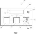
- the present disclosure is directed to a fall detection system 100 configured for automatically detecting a fall event and issuing an alert that the fall event has occurred.
- the fall detection system 100 may be configured to detect a type of a fall event and activate an alarm based on the type of the fall event. Additionally, the fall detection system 100 may be configured to detect an orientation of the user relative to a reference plane after the fall event.
- the fall detection system 100 is used with other equipment worn by the user, in form of a self-contained breathing apparatus (SCBA).
- SCBA self-contained breathing apparatus
- the fall detection system 100 has at least one sensor 102 (hereinafter referred to as "sensor 102") configured for detecting orientation and acceleration of a host, such as a user or an object configured to be worn by the user, in a three-dimensional space.
- the sensor 102 is operatively connected to a controller 104 configured for receiving information detected by the sensor 102, analyzing the information detected by the sensor 102 to determine whether the information is indicative of a fall event, and activate one or more indicator devices 106 (hereinafter referred to as "indicator device 106”) if a fall event is detected.
- the senor 102, controller 104, and indicator device 106 may be received within a housing 108 to define an integrated fall detection system 100.
- the housing 108 may be sealed to prevent water intrusion into an interior of the housing that receives the sensor 102, controller 104, and indicator device 106.
- the housing 108 may be made from a material that is resistant to heat such that functionality of the fall detection system 100 can be maintained even with exposure of the housing 108 to high heat (500 °F).
- the components of the fall detection system 100 may be provided as separate items configured for interacting together.
- the fall detection system 100 may have a power source 110 for powering various components of the fall detection system 100.
- the power source 110 may be integral with the housing 108 such that a single power source 110 provides power to the sensor 102, the controller 104, and the indicator device 106. In other examples, a plurality of power sources 110 may be provided, with each power source 110 powering at least one of the sensor 102, the controller 104, and the indicator device 106.
- the fall detection system 100 is configured to be worn by a user indirectly, such as by being connected to equipment that is carried by the user.
- the fall detection system 100 may be in the form of a bracelet, necklace, belt, or other accessory that is worn by the user, such as by being attached to the user's wrist, waist, neck, or other body part.
- the fall detection system 100 may be connected to a backpack or other accessory that is carried by the user.
- the sensor 102 of the fall detection system 100 is connected to the user in such manner as to be capable of sensing a change in position of the user's body over time, such as acceleration, orientation, and distance.
- the sensor 102 may be an electronic or electromechanical device that is configured to measure acceleration.
- the sensor 102 may be configured to measure static acceleration, such as gravity, and/or dynamic acceleration, such as forces due to movement or vibration.
- the sensor 102 may be an accelerometer configured for detecting acceleration in three reference axes (i.e., translation in X, Y, and Z axes).
- the sensor 102 may be an accelerometer configured for detecting acceleration in three reference axes and rotation about each of the three axes (i.e., a 6-axis accelerometer).
- the sensor 102 may be an omni-directional magnetometer. By measuring a magnitude of static acceleration due to gravity, the sensor 102 can be used to determine an angle at which the fall detection device 100 is tilted relative to the ground. Similarly, by sensing a magnitude of dynamic acceleration, the sensor 102 can be used to determine a direction in which the fall detection device 100 is moving.
- the sensor 102 may be operated continuously, or intermittently, such as in pre-determined active intervals separated by pre-determined inactive intervals. In each embodiment or aspect, the sensor 102 is configured for sensing for acceleration of the fall detection device 100 having pre-determined characteristics that are indicative of a fall event.
- the senor 102 may be a single sensor, or an array of two or more sensors described hereinabove.
- the sensor 102 may have a plurality of single- or dual-axis accelerometers combined together and configured for sensing acceleration due to translation and/or rotation in a three-dimensional space defined by, for example, a Cartesian coordinate system.
- the data obtained by the sensor 102 is communicated to the controller 104, such as by a wired or wireless connection, for analyzing and determining whether the data contains any of the pre-determined characteristics of a fall event that the sensor 102 is configured to detect.
- the pre-determined characteristics may include free fall, impact, and lack of motion.
- the controller 104 can activate the indicator device 106 to provide an alert that a fall event has occurred.
- the controller 104 includes, or is operable to execute appropriate custom-designed or conventional software to perform and implement the processing steps of the method and system of the present disclosure, thereby forming a specialized and particular computing system.
- the controller 104 may include a variety of discrete computer-readable media components for analyzing information sensed by the sensor 102 and for activating the indicator device 106 when the information contains pre-determined characteristics indicative of a fall event.
- this computer-readable media may include any media that can be accessed by the controller 104, such as volatile media, non-volatile media, removable media, non-removable media, transitory media, non-transitory media, etc.
- this computer-readable media may include computer storage media, such as media implemented in any method or technology for storage of information, such as computer-readable instructions, data structures, program modules, or other data; random access memory (RAM), read only memory (ROM), electrically erasable programmable read only memory (EEPROM), flash memory, or other memory technology; CD-ROM, digital video disks (DVDs), or other optical disk storage; magnetic cassettes, magnetic tape, magnetic disk storage, or other magnetic storage devices; or any other medium which can be used to store the desired information and which can be accessed by the controller 104.
- RAM random access memory
- ROM read only memory
- EEPROM electrically erasable programmable read only memory
- flash memory or other memory technology
- CD-ROM compact discs
- DVDs digital video disks
- magnetic cassettes magnetic tape, magnetic disk storage, or other magnetic storage devices; or any other medium which can be used to store the desired information and which can be accessed by the controller 104.
- this computer-readable media may include communications media, such as computer-readable instructions, data structures, program modules, or other data in a modulated data signal, such as a carrier wave or other transport mechanism and may include any information delivery media, wired media (such as a wired network and a direct-wired connection), and wireless media (such as acoustic signals, radio frequency signals, optical signals, infrared signals, biometric signals, bar code signals, etc.).
- a system memory with computer storage media in the form of volatile and non-volatile memory, such as ROM and RAM.
- a basic input/output system (BIOS) with appropriate computer-based routines assists in transferring information between components within the controller 104 and is normally stored in ROM.
- the RAM portion of the system memory typically contains data and program modules that are immediately accessible to or presently being operated on by the processing unit, e.g., an operating system, application programming interfaces, application programs, program modules, program data, and other instruction-based computer-readable codes.
- the controller 104 may activate, by wired or wireless control, the indicator device 106.
- the indicator device 106 may be a visual indicator device 106a, an audible indicator device 106b, a remote signaling indicator device 106c, or any combination thereof.
- the indicator device 106 may have one or more lights, such as one or more light-emitting diodes (LEDs), that are illuminated when the controller 104 activates the indicator device 106.
- the one or more lights may be lit continuously when the indicator device 106 is activated. Alternatively, the one or more lights may be lit intermittently at a pre-determined interval or sequence.
- the visual indicator device 106a may be provided on the housing 108 and/or on an external device in communication with the fall detection device 100.
- the visual indicator device 106a may be provided on a helmet worn by the user or another component connected to or worn by the user.
- the visual indicator device 106a may have at least one infrared light source configured for being detected with a thermal imaging sensor.
- the indicator device 106 may be an audio indicator device 106b having at least one speaker and/or a piezo buzzer. The at least one speaker and/or a piezo buzzer may be integrated with the housing 108 of the fall detection device 100, and/or on an external device in communication with the fall detection device 100.
- the indicator device 106 may be a remote signaling indicator device 106c configured to provide a remote signal to an external device.
- the indicator device 106 can wirelessly send a signal to an external device to indicate that a fall event has occurred.
- the remote signal can be a long-range (900 MHz) or a short-range (2,400 MHz) signal.
- the short-range signal may be configured for transmission from the fall detection device 100 to another local device, such as another user.
- the long range signal may be configured for transmission from the fall detection device 100 to a remote device using a cellular telephone network, or base stations with mobile or main command centers.
- the remote device may be an incident command center at a fire scene.
- the indicator device 106 may be configured to indicate a position of the fall detection device 100 after a fall event has been detected.
- the indicator device 106 may be configured to activate different types of alarms based on different fall events. For example, the indicator device 106 may activate a first indicator type, such as the visual indicator device 106a, if the fall event that is detected by the sensor 102 is indicative of falling down a set of stairs. The indicator device 106 may activate a second indicator type, such as the remote signaling indicator device 106c, if the fall event that is detected by the sensor 102 is indicative of a building collapse.
- a plurality of indicator devices 106 can be activated simultaneously or sequentially depending on the type of fall event that is detected by the sensor 102.
- the indicator device 106 may be reset after it has been activated.
- a reset mechanism 112 such as a button, may be provided to turn off the indicator device 106 after activation.
- the reset mechanism 112 may be provided directly on the housing 108 of the fall detection system 100 to allow manual resetting of the indicator device 106 by the user.
- the reset mechanism 112 may be provided on an external device in wireless communication with the fall detection system 100 to allow for remote resetting of the indicator device 106.
- the fall detection system 100 is integrated on equipment configured to be carried or worn by the user. In some embodiments or aspects, the fall detection system 100 may be used contrary to the claimed subject matter with a helmet worn on a user's head. In the claimed subject matter, the fall detection system 100 is configured for use with a self-contained breathing apparatus (SCBA).
- SCBA self-contained breathing apparatus
- SCBAs may be configured for use in a variety of applications, such as firefighting and industrial use.
- an SCBA 200 has a tank 202, a pressure regulator 204 connected to the tank 202, and an air line 206 connecting the pressure regulator 204 to a mask 208.
- the tank 202 is mounted and supported on a rigid frame 210 that is worn on a user's back.
- a pair of shoulder straps 212 and a belt strap 214 are connected to the frame 210.
- the shoulder straps 212 and the belt strap 214 are configured to enable wearing of the SCBA 200 in a manner similar to a backpack, where the tank 202 and the frame 210 are positioned on the user's back.
- the fall detection system 100 is integrated with the SCBA 200 At least a portion of the fall detection system 100 is connected to the frame 210 of the SCBA 200 . At least the sensor 102 of the fall detection system 100 is positioned on the frame 210 of the SCBA 200. Positioning of at least a portion of the fall detection system 100 on the frame 210 provides several advantages. When worn by the user, the frame 210 is positioned close to the center of gravity of the user, regardless of the user's height and weight. In addition, the position of the frame 210 remains substantially unchanged relative to the user's body. In this manner, readings from the sensor 102 may be used to determine the orientation of the user based on the orientation of the frame 210.
- the fall detection system 100 may be configured to detect changes in orientation of the sensor 102 (and, therefore, changes in orientation of the user), measure acceleration experienced by the sensor 102 (and, therefore, a force experienced by the user), and sense movement of the sensor 102 (and, therefore, movement of the user). This information can be used by the controller 104 as criteria for analyzing whether movement of the sensor 102 (and, therefore, movement of the user) in a three-dimensional space can be characterized as a fall event.
- the sensor 102 can be used to detect the orientation of the frame 210, and therefore the orientation of the user. Information detected by the sensor 102 can be used by the controller 104 to determine whether the orientation of the frame 210, and therefore the orientation of the user, falls within an expected orientation.
- an expected orientation of the sensor 102 may be a vertical orientation (i.e., substantially perpendicular to the ground) at a height of approximately 36 inches from the ground, or a horizontal orientation (i.e., substantially parallel to the ground) and vertically offset relative to the ground at approximately 24 inches.
- Orientations of the sensor 102 that are not within these expected orientations (or within a pre-determined range from these expected orientations) may indicate that the user has fallen and may need assistance.
- non-typical orientations of the user include, without limitation, if the user is upside-down or lying on his/her back.
- data from the sensor 102 regarding the orientation of the sensor 102 may be used by the controller 104 as criteria for deciding whether an alarm mode should be initiated by activating the indicator device 106.
- the controller 104 may use non-typical orientation of the sensor 102 (and, therefore, the user) as a trigger condition for initiating the alarm mode.
- the fall detection system 100 may use information regarding acceleration that is detected by the sensor 102 and correlate this information to a force experienced by the user. In some examples, the fall detection system 100 may use information regarding a magnitude and duration of acceleration during the acceleration event that is detected by the sensor 102, and correlate this information to a force experienced by the user.
- the controller 104 can initiate an alarm mode by activating the indicator device 106 if the acceleration magnitude (and, optionally, acceleration duration) exceeds a pre-determined threshold (3 G). For example, a zero acceleration measurement in the vertical axis is indicative of a free fall condition.
- This zero acceleration measurement may be followed by a large positive acceleration, such as when the user hits the ground after free falling. If the positive measurement in acceleration after a zero measurement exceeds a pre-determined threshold (3 G), the controller 104 may initiate the alarm mode by activating the indicator device 106. Some acceleration events are typical (i.e. jumping off of a truck), while others (falling off of a roof, getting hit by a brick) can cause injury to the user. In this manner, acceleration events that are below the pre-determined threshold can be ignored, while acceleration events that are above the pre-determined threshold will result in activation of the indicator device 106 to provide an alert that the user has fallen.
- a pre-determined threshold 3 G
- the fall detection system 100 may use information regarding motion of the sensor 102 (and, therefore, the user) after experiencing an acceleration event.
- the controller 104 may be configured to detect whether the user is stationary or moving after experiencing an acceleration event. For example, if a user is not moving within a pre-determined period of time, such as 0 to 5 seconds, after experiencing an acceleration event, this information may be indicative that the user has fallen and is unable to move.
- the controller 104 can activate the indicator device 106 to indicate that the user has fallen and that assistance is needed.
- the controller 104 analyzes data from the sensor 102 relating to the orientation of the user before an acceleration event, acceleration magnitude during the fall, acceleration magnitude during impact, final orientation of the user, and movement after the fall to determine whether an alarm should be activated.
- the user in a fall from an elevated position, such as when falling from a roof, the user may be initially in an upright position and end in a non-vertical position after falling.
- the user will experience zero acceleration during free falling, and a large acceleration upon impact.
- the controller 104 can automatically activate the indicator device 106 depending on whether the user is able to move within a pre-determined period of time (0 to 5 seconds) after falling.
- the controller 104 can determine whether this information is indicative of a fall event, such as one of the fall events listed in Table I above, and automatically activate the indicator device 106.
- the controller 104 may activate the indicator device 106 to communicate, via short-range signals, to other users in the vicinity of the fallen user. In this manner, other users can provide assistance to the fallen user.
- the indicator device 106 may provide a visual or audible indication to the user that a fall event has occurred and ask the user to acknowledge whether assistance is needed. For example, the user can turn off the indicator device 106 via the reset mechanism 112 if the user is able to safely move after experiencing the fall event.
- the sensor 102 is configured to detect an initial position of the user (block 300) (e.g., standing or crawling), and use this value as a reference position.
- the controller 104 may continuously update the reference position to account for changes in the position of the user during use of the fall detection system 100.
- the sensor 102 is configured to detect all movement of the user in a three-dimensional space and correlate such movement to an acceleration measurement (block 302). Using the sensor data, the controller 104 determines whether the acceleration measured by the sensor 102 exceeds a pre-determined threshold value (block 304).
- the controller 104 continues to monitor the sensor data for any acceleration value that may exceed the acceleration threshold. If the controller 104 detects that the acceleration data from the sensor 102 exceeds the pre-determined threshold, the controller 104 analyzes sensor data regarding the position of the user after the acceleration event (block 306). The controller 104 also analyzes sensor data regarding movement of the user after the acceleration event (block 308). If movement of the user is detected within a predetermined length of time after the acceleration event, the controller 104 will not activate an alarm mode (block 310). However, if no movement of the user is detected within the predetermined length of time after the acceleration event, the controller 104 activates the alarm mode, wherein the indicator device 106 is activated to indicate that the user has fallen.
Landscapes
- Health & Medical Sciences (AREA)
- General Health & Medical Sciences (AREA)
- Gerontology & Geriatric Medicine (AREA)
- Business, Economics & Management (AREA)
- Emergency Management (AREA)
- Physics & Mathematics (AREA)
- General Physics & Mathematics (AREA)
- Psychiatry (AREA)
- Psychology (AREA)
- Social Psychology (AREA)
- Emergency Alarm Devices (AREA)
- Alarm Systems (AREA)
Claims (15)
- Sturzerkennungssystem (100), umfassend:zumindest einen Sensor (102), der zum Erkennen von Beschleunigung und Ausrichtung eines Benutzers ausgelegt ist;zumindest eine Anzeigevorrichtung (106) mit einem Alarmmodus; undeine Steuerung (104), die mit dem zumindest einen Sensor (102) und der zumindest einen Anzeigevorrichtung (106) wirkverbunden ist, wobei die Steuerung (104) programmiert oder ausgelegt ist zum:Empfangen von Daten, die durch den zumindest einen Sensor (102) erzeugt werden;Vergleichen zumindest eines Teils der empfangenen Daten mit zumindest einem spezifizierten Parameter, der auf ein Sturzereignis hinweist; undbasierend auf dem Vergleich, Aktivieren oder Veranlassen der Aktivierung der zumindest einen Anzeigevorrichtung (106) zum Eintritt in den Alarmmodus,wobei der zumindest eine spezifizierte Parameter zumindest eines der folgenden umfasst: eine Beschleunigung, die einen vorbestimmten Schwellenwert überschreitet, eine Änderung zwischen einer Anfangsausrichtung des Benutzers vor einem Beschleunigungsereignis und einer Endausrichtung des Benutzers nach dem Beschleunigungsereignis, eine fehlende Bewegung des Benutzers für eine vorbestimmte Zeitspanne nach dem Beschleunigungsereignis oder eine Kombination davon, dadurch gekennzeichnet, dass,das Sturzerkennungssystem (100) in ein unabhängiges Atemschutzgerät, SCBA, (200) integriert ist, indem zumindest ein Teil des Sturzerkennungssystems (100) mit einem starren Rahmen (210) des SCBA (200) verbunden ist, wobei der Rahmen (210) in der Nähe eines Schwerpunkts des Benutzers positioniert ist, um die Ausrichtung des Benutzers basierend auf einer Ausrichtung des zumindest einen Sensors (102) zu bestimmen.
- Sturzerkennungssystem nach Anspruch 1, wobei der vorbestimmte Schwellenwert für das Beschleunigungsereignis zumindest etwa 3 G beträgt.
- Sturzerkennungssystem nach Anspruch 1 oder 2, wobei die vorbestimmte Zeitspanne nach dem Beschleunigungsereignis in dem Bereich von 0 bis etwa 5 Sekunden liegt.
- Sturzerkennungssystem nach einem der vorhergehenden Ansprüche, wobei der zumindest eine Sensor (102) zum Erkennen von zumindest entweder statischer Beschleunigung oder dynamischer Beschleunigung ausgelegt ist.
- Sturzerkennungssystem nach einem der vorhergehenden Ansprüche, wobei der zumindest eine Sensor (102) zumindest einer der folgenden ist: ein 3-Achsen-Beschleunigungsmesser, ein 6-Achsen-Beschleunigungsmesser, ein omnidirektionaler Magnetometer oder eine Kombination davon.
- Sturzerkennungssystem nach Anspruch 1, wobei die zumindest eine Anzeigevorrichtung (106) eine optische Anzeigevorrichtung (106a) ist, insbesondere mindestens eines von einer Leuchtdiode und einem Infrarotstrahler.
- Sturzerkennungssystem nach Anspruch 1, wobei die zumindest eine Anzeigevorrichtung (106) eine akustische Anzeigevorrichtung (106b), insbesondere zumindest ein Lautsprecher oder ein Piezo-Summer ist.
- Sturzerkennungssystem nach Anspruch 1, wobei die zumindest eine Anzeigevorrichtung (106) eine Fernsignalanzeigevorrichtung (106c) ist, die für eine drahtlose Kommunikation mit zumindest einer entfernten Vorrichtung programmiert oder ausgelegt ist, insbesondere um zumindest eines von einem drahtlosen Kurzstreckensignal und einem drahtlosen Langstreckensignal an die zumindest eine entfernte Vorrichtung zu senden.
- Sturzerkennungssystem nach einem der vorhergehenden Ansprüche, ferner umfassend einen Rücksetzmechanismus zum Ausschalten der zumindest einen Anzeigevorrichtung nach der Aktivierung.
- Unabhängiges Atemschutzgerät, SCBA, (200), umfassend:einen an einem starren Rahmen (210) montierten Tank, der zur Befestigung auf dem Rücken eines Benutzers unter Verwendung eines oder mehrerer Gurte (212, 214) ausgelegt ist; undein Sturzerkennungssystem (100) nach einem der vorhergehenden Ansprüche, wobei:
der Benutzer den starren Rahmen (210) trägt. - SCBA nach Anspruch 10, wobei der vorbestimmte Schwellenwert für das Beschleunigungsereignis zumindest etwa 3 G beträgt und die vorbestimmte Zeitspanne nach dem Beschleunigungsereignis in dem Bereich von etwa 0 Sekunden bis etwa 5 Sekunden liegt.
- SCBA nach Anspruch 10 oder 11, wobei der zumindest eine Sensor (102) zum Erkennen von zumindest einer von statischer Beschleunigung und dynamischer Beschleunigung ausgelegt ist.
- SCBA nach einem der Ansprüche 10 bis 12, wobei der zumindest eine Sensor (102) zumindest einer der folgenden ist: ein 3-Achsen-Beschleunigungsmesser, ein 6-Achsen-Beschleunigungsmesser, ein omnidirektionaler Magnetometer oder eine Kombination davon.
- SCBA nach einem der Ansprüche 10 bis 13, wobei die zumindest eine Anzeigevorrichtung (106) zumindest eine von einer optischen Anzeigevorrichtung (106a), einer akustischen Anzeigevorrichtung (106b) oder einer Fernsignalanzeigevorrichtung (106c) ist.
- SCBA nach einem der Ansprüche 10 bis 14, ferner umfassend einen Rücksetzmechanismus (112) zum Abschalten der zumindest einen Anzeigevorrichtung (106) nach der Aktivierung.
Applications Claiming Priority (3)
| Application Number | Priority Date | Filing Date | Title |
|---|---|---|---|
| US201662323266P | 2016-04-15 | 2016-04-15 | |
| US15/486,897 US10043368B1 (en) | 2017-04-13 | 2017-04-13 | Fall detection system |
| PCT/US2017/027586 WO2017180979A1 (en) | 2016-04-15 | 2017-04-14 | Fall detection system |
Publications (2)
| Publication Number | Publication Date |
|---|---|
| EP3443547A1 EP3443547A1 (de) | 2019-02-20 |
| EP3443547B1 true EP3443547B1 (de) | 2025-04-02 |
Family
ID=58633120
Family Applications (1)
| Application Number | Title | Priority Date | Filing Date |
|---|---|---|---|
| EP17719790.2A Active EP3443547B1 (de) | 2016-04-15 | 2017-04-14 | Falldetektionssystem |
Country Status (3)
| Country | Link |
|---|---|
| EP (1) | EP3443547B1 (de) |
| CN (1) | CN109074718A (de) |
| WO (1) | WO2017180979A1 (de) |
Families Citing this family (10)
| Publication number | Priority date | Publication date | Assignee | Title |
|---|---|---|---|---|
| US10512801B2 (en) * | 2018-04-20 | 2019-12-24 | Honeywell International Inc. | Distance-learning safety retraction lanyard |
| EP4600928A3 (de) * | 2019-01-14 | 2026-02-25 | MSA Technology, LLC | Sturzschutz-compliance-system und -verfahren |
| CN111476972A (zh) * | 2019-01-24 | 2020-07-31 | 上海杰航文化传播有限公司 | 一种智能医疗报警系统 |
| EP3996819A4 (de) * | 2019-07-10 | 2023-08-02 | 3M Innovative Properties Company | Fallschutzvorrichtung mit multimodaler induktiver abtastung |
| CN110390796A (zh) * | 2019-08-02 | 2019-10-29 | 浙江工业职业技术学院 | 一种楼层防坠方法 |
| EP3800721A1 (de) | 2019-10-01 | 2021-04-07 | Hilti Aktiengesellschaft | Vorrichtung zum erfassen eines kritischen sturzes |
| EP3904012A1 (de) * | 2020-04-28 | 2021-11-03 | Hilti Aktiengesellschaft | Vorrichtung zum erfassen eines kritischen sturzes |
| CN115346337B (zh) | 2022-08-23 | 2023-07-21 | 云南电网有限责任公司电力科学研究院 | 防止作业人员坠落的方法、控制器、安全带和存储介质 |
| CN116311839A (zh) * | 2023-05-23 | 2023-06-23 | 深圳市致尚信息技术有限公司 | 一种机顶盒摔落报警方法、装置及电子设备 |
| CN120172229B (zh) * | 2025-05-22 | 2025-08-26 | 上海市安装工程集团有限公司 | 一种竖井内的智能吊装机构及其应用方法 |
Family Cites Families (12)
| Publication number | Priority date | Publication date | Assignee | Title |
|---|---|---|---|---|
| US6611783B2 (en) * | 2000-01-07 | 2003-08-26 | Nocwatch, Inc. | Attitude indicator and activity monitoring device |
| US7263379B1 (en) * | 2002-12-23 | 2007-08-28 | Sti Licensing Corp. | Communications network for emergency services personnel |
| US7155388B2 (en) * | 2004-06-30 | 2006-12-26 | Motorola, Inc. | Method and apparatus for characterizing inhalation noise and calculating parameters based on the characterization |
| US7191089B2 (en) * | 2004-12-01 | 2007-03-13 | Freescale Semiconductor, Inc. | System and method for fall detection |
| KR20070102588A (ko) * | 2005-01-31 | 2007-10-18 | 히타치 긴조쿠 가부시키가이샤 | 낙하 검지 방법 및 낙하 검지 장치 |
| CN101650869B (zh) * | 2009-09-23 | 2012-01-04 | 中国科学院合肥物质科学研究院 | 一种人体摔倒自动检测并报警的装置及其信息处理方法 |
| CN102044131B (zh) * | 2010-07-20 | 2013-12-11 | 北京紫峰华纳科技有限公司 | 一种报警信号处理方法及基于人体体位信息的报警方法 |
| US9554659B2 (en) * | 2012-10-22 | 2017-01-31 | Uwm Research Foundation, Inc. | Infant sleep pod |
| CN102961833B (zh) * | 2012-11-01 | 2015-04-01 | 浙江大学 | 高空防护服 |
| CN203111102U (zh) * | 2013-03-21 | 2013-08-07 | 江苏物联网研究发展中心 | 基于三轴加速度传感器的载人车辆坠落感知与保护系统 |
| EP3043709B1 (de) * | 2013-09-11 | 2019-06-19 | Koninklijke Philips N.V. | Falldetektionssystem und verfahren |
| GB201317249D0 (en) * | 2013-09-27 | 2013-11-13 | Scott Health & Safety Ltd | Carrying plate for breathing apparatus |
-
2017
- 2017-04-14 EP EP17719790.2A patent/EP3443547B1/de active Active
- 2017-04-14 CN CN201780023403.XA patent/CN109074718A/zh active Pending
- 2017-04-14 WO PCT/US2017/027586 patent/WO2017180979A1/en not_active Ceased
Also Published As
| Publication number | Publication date |
|---|---|
| WO2017180979A1 (en) | 2017-10-19 |
| CN109074718A (zh) | 2018-12-21 |
| EP3443547A1 (de) | 2019-02-20 |
Similar Documents
| Publication | Publication Date | Title |
|---|---|---|
| US10043368B1 (en) | Fall detection system | |
| EP3443547A1 (de) | Falldetektionssystem | |
| CN110198763B (zh) | 智能高度安全系统 | |
| US20180148144A1 (en) | Personal Safety Device | |
| US10828517B2 (en) | Smart fall arrest system | |
| KR101595850B1 (ko) | 안전 경보 기능이 구비된 개인용 공기호흡기 | |
| JP6936546B2 (ja) | 安全帯フックかけ忘れ防止監視システム | |
| US10232198B2 (en) | Method for detecting a fall of a worker and apparatus for detecting a fall of a worker | |
| EP2991052B1 (de) | Mehrsensoren-bewegungserfassung in umluftunabhängigen atemschutzgeräten | |
| KR100981660B1 (ko) | 소방관의 개인안전 감시 시스템 | |
| EP4217982B1 (de) | In der höhe angebrachtes sicherheitssystem und verfahren zu dessen verwendung | |
| US9589437B2 (en) | Permissions-based alarm system and method | |
| EP1779772A1 (de) | System zur auswertung der aktivität einer person und zum automatischen nachweis von stürzen | |
| KR102296382B1 (ko) | 위험 감지 기능을 갖는 소방관용 보호장비 | |
| KR102217765B1 (ko) | 고소작업자 추락방지용 안전구 및 이를 이용한 안전 시스템 | |
| US8264365B2 (en) | Motion sensing remote microphone | |
| KR20210050730A (ko) | 고소작업자 추락방지용 경보장치 | |
| KR20030017597A (ko) | 소방관 위치파악시스템 및 그 방법 | |
| WO2025175403A1 (en) | Work at heights safety hook monitoring system | |
| JP7064730B2 (ja) | 管理システム | |
| WO2015135161A1 (en) | An arrester device and a system for monitoring thereof | |
| CN210494939U (zh) | 一种智慧型安全带装置 | |
| KR102227115B1 (ko) | 고소작업대의 운전자와 작업자의 동작감지를 통한 충돌 및 협착 방지 시스템 | |
| ES1298466U (es) | Alarma de seguridad en escalada para dispositivos de descenso automatico en rocodromos | |
| KR20240175746A (ko) | 익수 사고 조기 경보 시스템 및 그 방법 |
Legal Events
| Date | Code | Title | Description |
|---|---|---|---|
| STAA | Information on the status of an ep patent application or granted ep patent |
Free format text: STATUS: UNKNOWN |
|
| STAA | Information on the status of an ep patent application or granted ep patent |
Free format text: STATUS: THE INTERNATIONAL PUBLICATION HAS BEEN MADE |
|
| PUAI | Public reference made under article 153(3) epc to a published international application that has entered the european phase |
Free format text: ORIGINAL CODE: 0009012 |
|
| STAA | Information on the status of an ep patent application or granted ep patent |
Free format text: STATUS: REQUEST FOR EXAMINATION WAS MADE |
|
| 17P | Request for examination filed |
Effective date: 20181015 |
|
| AK | Designated contracting states |
Kind code of ref document: A1 Designated state(s): AL AT BE BG CH CY CZ DE DK EE ES FI FR GB GR HR HU IE IS IT LI LT LU LV MC MK MT NL NO PL PT RO RS SE SI SK SM TR |
|
| AX | Request for extension of the european patent |
Extension state: BA ME |
|
| DAV | Request for validation of the european patent (deleted) | ||
| DAX | Request for extension of the european patent (deleted) | ||
| STAA | Information on the status of an ep patent application or granted ep patent |
Free format text: STATUS: EXAMINATION IS IN PROGRESS |
|
| 17Q | First examination report despatched |
Effective date: 20201209 |
|
| P01 | Opt-out of the competence of the unified patent court (upc) registered |
Effective date: 20230626 |
|
| GRAP | Despatch of communication of intention to grant a patent |
Free format text: ORIGINAL CODE: EPIDOSNIGR1 |
|
| STAA | Information on the status of an ep patent application or granted ep patent |
Free format text: STATUS: GRANT OF PATENT IS INTENDED |
|
| INTG | Intention to grant announced |
Effective date: 20240704 |
|
| GRAJ | Information related to disapproval of communication of intention to grant by the applicant or resumption of examination proceedings by the epo deleted |
Free format text: ORIGINAL CODE: EPIDOSDIGR1 |
|
| STAA | Information on the status of an ep patent application or granted ep patent |
Free format text: STATUS: EXAMINATION IS IN PROGRESS |
|
| GRAS | Grant fee paid |
Free format text: ORIGINAL CODE: EPIDOSNIGR3 |
|
| STAA | Information on the status of an ep patent application or granted ep patent |
Free format text: STATUS: GRANT OF PATENT IS INTENDED |
|
| GRAP | Despatch of communication of intention to grant a patent |
Free format text: ORIGINAL CODE: EPIDOSNIGR1 |
|
| INTC | Intention to grant announced (deleted) | ||
| INTG | Intention to grant announced |
Effective date: 20241212 |
|
| GRAA | (expected) grant |
Free format text: ORIGINAL CODE: 0009210 |
|
| STAA | Information on the status of an ep patent application or granted ep patent |
Free format text: STATUS: THE PATENT HAS BEEN GRANTED |
|
| AK | Designated contracting states |
Kind code of ref document: B1 Designated state(s): AL AT BE BG CH CY CZ DE DK EE ES FI FR GB GR HR HU IE IS IT LI LT LU LV MC MK MT NL NO PL PT RO RS SE SI SK SM TR |
|
| REG | Reference to a national code |
Ref country code: GB Ref legal event code: FG4D |
|
| REG | Reference to a national code |
Ref country code: CH Ref legal event code: EP |
|
| REG | Reference to a national code |
Ref country code: DE Ref legal event code: R096 Ref document number: 602017088666 Country of ref document: DE |
|
| REG | Reference to a national code |
Ref country code: IE Ref legal event code: FG4D |
|
| PGFP | Annual fee paid to national office [announced via postgrant information from national office to epo] |
Ref country code: DE Payment date: 20250507 Year of fee payment: 9 |
|
| PGFP | Annual fee paid to national office [announced via postgrant information from national office to epo] |
Ref country code: FR Payment date: 20250526 Year of fee payment: 9 |
|
| REG | Reference to a national code |
Ref country code: NL Ref legal event code: MP Effective date: 20250402 |
|
| PG25 | Lapsed in a contracting state [announced via postgrant information from national office to epo] |
Ref country code: NL Free format text: LAPSE BECAUSE OF FAILURE TO SUBMIT A TRANSLATION OF THE DESCRIPTION OR TO PAY THE FEE WITHIN THE PRESCRIBED TIME-LIMIT Effective date: 20250402 |
|
| REG | Reference to a national code |
Ref country code: AT Ref legal event code: MK05 Ref document number: 1782081 Country of ref document: AT Kind code of ref document: T Effective date: 20250402 |
|
| PG25 | Lapsed in a contracting state [announced via postgrant information from national office to epo] |
Ref country code: PT Free format text: LAPSE BECAUSE OF FAILURE TO SUBMIT A TRANSLATION OF THE DESCRIPTION OR TO PAY THE FEE WITHIN THE PRESCRIBED TIME-LIMIT Effective date: 20250804 Ref country code: ES Free format text: LAPSE BECAUSE OF FAILURE TO SUBMIT A TRANSLATION OF THE DESCRIPTION OR TO PAY THE FEE WITHIN THE PRESCRIBED TIME-LIMIT Effective date: 20250402 Ref country code: FI Free format text: LAPSE BECAUSE OF FAILURE TO SUBMIT A TRANSLATION OF THE DESCRIPTION OR TO PAY THE FEE WITHIN THE PRESCRIBED TIME-LIMIT Effective date: 20250402 |
|
| REG | Reference to a national code |
Ref country code: LT Ref legal event code: MG9D |
|
| PG25 | Lapsed in a contracting state [announced via postgrant information from national office to epo] |
Ref country code: NO Free format text: LAPSE BECAUSE OF FAILURE TO SUBMIT A TRANSLATION OF THE DESCRIPTION OR TO PAY THE FEE WITHIN THE PRESCRIBED TIME-LIMIT Effective date: 20250702 Ref country code: GR Free format text: LAPSE BECAUSE OF FAILURE TO SUBMIT A TRANSLATION OF THE DESCRIPTION OR TO PAY THE FEE WITHIN THE PRESCRIBED TIME-LIMIT Effective date: 20250703 |
|
| PG25 | Lapsed in a contracting state [announced via postgrant information from national office to epo] |
Ref country code: PL Free format text: LAPSE BECAUSE OF FAILURE TO SUBMIT A TRANSLATION OF THE DESCRIPTION OR TO PAY THE FEE WITHIN THE PRESCRIBED TIME-LIMIT Effective date: 20250402 |
|
| PG25 | Lapsed in a contracting state [announced via postgrant information from national office to epo] |
Ref country code: BG Free format text: LAPSE BECAUSE OF FAILURE TO SUBMIT A TRANSLATION OF THE DESCRIPTION OR TO PAY THE FEE WITHIN THE PRESCRIBED TIME-LIMIT Effective date: 20250402 |
|
| PG25 | Lapsed in a contracting state [announced via postgrant information from national office to epo] |
Ref country code: HR Free format text: LAPSE BECAUSE OF FAILURE TO SUBMIT A TRANSLATION OF THE DESCRIPTION OR TO PAY THE FEE WITHIN THE PRESCRIBED TIME-LIMIT Effective date: 20250402 |
|
| PG25 | Lapsed in a contracting state [announced via postgrant information from national office to epo] |
Ref country code: AT Free format text: LAPSE BECAUSE OF FAILURE TO SUBMIT A TRANSLATION OF THE DESCRIPTION OR TO PAY THE FEE WITHIN THE PRESCRIBED TIME-LIMIT Effective date: 20250402 |
|
| PG25 | Lapsed in a contracting state [announced via postgrant information from national office to epo] |
Ref country code: RS Free format text: LAPSE BECAUSE OF FAILURE TO SUBMIT A TRANSLATION OF THE DESCRIPTION OR TO PAY THE FEE WITHIN THE PRESCRIBED TIME-LIMIT Effective date: 20250702 |
|
| PG25 | Lapsed in a contracting state [announced via postgrant information from national office to epo] |
Ref country code: IS Free format text: LAPSE BECAUSE OF FAILURE TO SUBMIT A TRANSLATION OF THE DESCRIPTION OR TO PAY THE FEE WITHIN THE PRESCRIBED TIME-LIMIT Effective date: 20250802 |
|
| PG25 | Lapsed in a contracting state [announced via postgrant information from national office to epo] |
Ref country code: LV Free format text: LAPSE BECAUSE OF FAILURE TO SUBMIT A TRANSLATION OF THE DESCRIPTION OR TO PAY THE FEE WITHIN THE PRESCRIBED TIME-LIMIT Effective date: 20250402 |
|
| REG | Reference to a national code |
Ref country code: CH Ref legal event code: H13 Free format text: ST27 STATUS EVENT CODE: U-0-0-H10-H13 (AS PROVIDED BY THE NATIONAL OFFICE) Effective date: 20251125 |
|
| PG25 | Lapsed in a contracting state [announced via postgrant information from national office to epo] |
Ref country code: LU Free format text: LAPSE BECAUSE OF NON-PAYMENT OF DUE FEES Effective date: 20250414 |
|
| REG | Reference to a national code |
Ref country code: BE Ref legal event code: MM Effective date: 20250430 |
|
| REG | Reference to a national code |
Ref country code: DE Ref legal event code: R097 Ref document number: 602017088666 Country of ref document: DE |
|
| PG25 | Lapsed in a contracting state [announced via postgrant information from national office to epo] |
Ref country code: DK Free format text: LAPSE BECAUSE OF FAILURE TO SUBMIT A TRANSLATION OF THE DESCRIPTION OR TO PAY THE FEE WITHIN THE PRESCRIBED TIME-LIMIT Effective date: 20250402 Ref country code: SM Free format text: LAPSE BECAUSE OF FAILURE TO SUBMIT A TRANSLATION OF THE DESCRIPTION OR TO PAY THE FEE WITHIN THE PRESCRIBED TIME-LIMIT Effective date: 20250402 |
|
| PG25 | Lapsed in a contracting state [announced via postgrant information from national office to epo] |
Ref country code: BE Free format text: LAPSE BECAUSE OF NON-PAYMENT OF DUE FEES Effective date: 20250430 |
|
| PG25 | Lapsed in a contracting state [announced via postgrant information from national office to epo] |
Ref country code: CH Free format text: LAPSE BECAUSE OF NON-PAYMENT OF DUE FEES Effective date: 20250430 |
|
| PG25 | Lapsed in a contracting state [announced via postgrant information from national office to epo] |
Ref country code: CZ Free format text: LAPSE BECAUSE OF FAILURE TO SUBMIT A TRANSLATION OF THE DESCRIPTION OR TO PAY THE FEE WITHIN THE PRESCRIBED TIME-LIMIT Effective date: 20250402 |
|
| PG25 | Lapsed in a contracting state [announced via postgrant information from national office to epo] |
Ref country code: EE Free format text: LAPSE BECAUSE OF FAILURE TO SUBMIT A TRANSLATION OF THE DESCRIPTION OR TO PAY THE FEE WITHIN THE PRESCRIBED TIME-LIMIT Effective date: 20250402 |
|
| PG25 | Lapsed in a contracting state [announced via postgrant information from national office to epo] |
Ref country code: SK Free format text: LAPSE BECAUSE OF FAILURE TO SUBMIT A TRANSLATION OF THE DESCRIPTION OR TO PAY THE FEE WITHIN THE PRESCRIBED TIME-LIMIT Effective date: 20250402 Ref country code: RO Free format text: LAPSE BECAUSE OF FAILURE TO SUBMIT A TRANSLATION OF THE DESCRIPTION OR TO PAY THE FEE WITHIN THE PRESCRIBED TIME-LIMIT Effective date: 20250402 |
|
| PG25 | Lapsed in a contracting state [announced via postgrant information from national office to epo] |
Ref country code: IT Free format text: LAPSE BECAUSE OF FAILURE TO SUBMIT A TRANSLATION OF THE DESCRIPTION OR TO PAY THE FEE WITHIN THE PRESCRIBED TIME-LIMIT Effective date: 20250402 |
|
| PG25 | Lapsed in a contracting state [announced via postgrant information from national office to epo] |
Ref country code: MC Free format text: LAPSE BECAUSE OF FAILURE TO SUBMIT A TRANSLATION OF THE DESCRIPTION OR TO PAY THE FEE WITHIN THE PRESCRIBED TIME-LIMIT Effective date: 20250402 |
|
| PLBE | No opposition filed within time limit |
Free format text: ORIGINAL CODE: 0009261 |
|
| STAA | Information on the status of an ep patent application or granted ep patent |
Free format text: STATUS: NO OPPOSITION FILED WITHIN TIME LIMIT |
|
| REG | Reference to a national code |
Ref country code: CH Ref legal event code: L10 Free format text: ST27 STATUS EVENT CODE: U-0-0-L10-L00 (AS PROVIDED BY THE NATIONAL OFFICE) Effective date: 20260211 |
|
| 26N | No opposition filed |
Effective date: 20260105 |
|
| PGFP | Annual fee paid to national office [announced via postgrant information from national office to epo] |
Ref country code: GB Payment date: 20260224 Year of fee payment: 10 |
|
| PG25 | Lapsed in a contracting state [announced via postgrant information from national office to epo] |
Ref country code: IE Free format text: LAPSE BECAUSE OF NON-PAYMENT OF DUE FEES Effective date: 20250414 |