EP3443603B1 - Dispositif de détente de pression pour un boitier de batterie, boitier de batterie avec dispositif de détente de pression, batterie, et procede de détente de pression d'une batterie - Google Patents
Dispositif de détente de pression pour un boitier de batterie, boitier de batterie avec dispositif de détente de pression, batterie, et procede de détente de pression d'une batterie Download PDFInfo
- Publication number
- EP3443603B1 EP3443603B1 EP17716922.4A EP17716922A EP3443603B1 EP 3443603 B1 EP3443603 B1 EP 3443603B1 EP 17716922 A EP17716922 A EP 17716922A EP 3443603 B1 EP3443603 B1 EP 3443603B1
- Authority
- EP
- European Patent Office
- Prior art keywords
- battery housing
- battery
- pressure
- separating element
- pressure relief
- Prior art date
- Legal status (The legal status is an assumption and is not a legal conclusion. Google has not performed a legal analysis and makes no representation as to the accuracy of the status listed.)
- Active
Links
Images


Classifications
-
- H—ELECTRICITY
- H01—ELECTRIC ELEMENTS
- H01M—PROCESSES OR MEANS, e.g. BATTERIES, FOR THE DIRECT CONVERSION OF CHEMICAL ENERGY INTO ELECTRICAL ENERGY
- H01M50/00—Constructional details or processes of manufacture of the non-active parts of electrochemical cells other than fuel cells, e.g. hybrid cells
- H01M50/30—Arrangements for facilitating escape of gases
- H01M50/342—Non-re-sealable arrangements
- H01M50/3425—Non-re-sealable arrangements in the form of rupturable membranes or weakened parts, e.g. pierced with the aid of a sharp member
-
- H—ELECTRICITY
- H01—ELECTRIC ELEMENTS
- H01M—PROCESSES OR MEANS, e.g. BATTERIES, FOR THE DIRECT CONVERSION OF CHEMICAL ENERGY INTO ELECTRICAL ENERGY
- H01M2220/00—Batteries for particular applications
- H01M2220/30—Batteries in portable systems, e.g. mobile phone, laptop
-
- Y—GENERAL TAGGING OF NEW TECHNOLOGICAL DEVELOPMENTS; GENERAL TAGGING OF CROSS-SECTIONAL TECHNOLOGIES SPANNING OVER SEVERAL SECTIONS OF THE IPC; TECHNICAL SUBJECTS COVERED BY FORMER USPC CROSS-REFERENCE ART COLLECTIONS [XRACs] AND DIGESTS
- Y02—TECHNOLOGIES OR APPLICATIONS FOR MITIGATION OR ADAPTATION AGAINST CLIMATE CHANGE
- Y02E—REDUCTION OF GREENHOUSE GAS [GHG] EMISSIONS, RELATED TO ENERGY GENERATION, TRANSMISSION OR DISTRIBUTION
- Y02E60/00—Enabling technologies; Technologies with a potential or indirect contribution to GHG emissions mitigation
- Y02E60/10—Energy storage using batteries
Definitions
- the invention relates to a pressure relief device for a battery housing, a battery housing with the pressure relief device, a battery with the battery housing and a method for pressure relief of a battery.
- electrically drivable vehicles e.g. pure electric vehicles, plug-in hybrid vehicles, serial hybrid vehicles
- rechargeable batteries based on lithium-ion are mainly used to supply the electric drive motor or the electric drive motors.
- Such batteries contain a plurality of rechargeable battery cells, which in turn have at least two electrodes, ie an anode and a cathode, which are electrically insulated from one another by an electrolyte-impregnated separator.
- the pressure compensation device Since water must be prevented from penetrating into the interior of the battery housing, the pressure compensation device generally has a pressure compensation membrane with micropores, for example a PTFE membrane, through which air can flow, but only through one due to the water drops due to the surface tension Can penetrate water column of 2 m or more. With the usual sizes of the pressure compensation membrane, the air exchange through the pores of the pressure compensation membrane is approximately 1000 cm 3 / min at a pressure difference of 10 mbar.
- thermo runaway in the event of overcharging or a short circuit, the energy contained in a single battery cell can be released suddenly, with the result that excessive heat is generated.
- an exothermic reaction of the cell chemistry begins (inter alia in connection with the release of oxygen from the metal oxides contained in the cell chemistry), which can lead to massive overheating and to outgassing or evaporating materials.
- the evaporating materials ignite.
- gas quantities of up to 400 L are generated within 0.3 to 3 seconds at a gas temperature of up to 800 ° C. Since battery housings are usually only designed for a maximum internal overpressure of 0.5 bar, and this internal overpressure is exceeded by a battery cell if a thermal breakdown occurs, a hermetically sealed battery housing would explode in such an event.
- the battery housing should therefore remain as intact as possible even if a battery cell or a battery goes through thermally, and the resulting amount of gas is discharged in a controlled manner to the outside.
- the pressure equalization membrane mentioned above does not allow a sufficiently large gas flow; rather, the pressure equalization membrane would simply bulge outwards without further measures due to the amount of gas generated in the battery housing and would only burst at about 3 bar, i.e. only above the excess pressure of about 0 , 5 bar, at which the battery housing is already destroyed.
- a solution known from the prior art for this purpose provides for a mandrel to be arranged on the outside of the opening in such a way that the pressure compensation diaphragm, which bulges outward in the event of overpressure in the interior of the battery housing, is pressed against the mandrel and punctured.
- the pressure equalization membrane which is often also called “bursting membrane” due to this process
- the membrane is only pierced without bursting. The excess pressure in the battery is then reduced in an uncontrolled manner by the battery housing bursting open.
- a plate-shaped element In front of the separating element, a plate-shaped element is arranged parallel to the separating element on the side of the separating element facing the inner region, the plate-shaped element being mechanically coupled to the holding element via a plastically or elastically deformable web.
- the plate-shaped element tilts about an axis given by the web and forms a crack on the separating element along an edge of the plate-shaped element which has penetrated into the surface of the separating element to divert the excess pressure.
- the plate-shaped element in the in the DE 10 2014 017 232 A1 proposed solution in the event of a dynamic pressure in the battery housing resulting from violent gas pressure being pressed securely against the separating element (the pressure compensation or bursting membrane) and this also tears reliably at the free edge of the plate-shaped element (the "sheet metal edge”).
- the plate-shaped element is then pressed further towards the outside of the battery housing, the edges of which, however, collide with the wall of a regularly existing connecting piece and / or the wall of an exhaust pipe.
- the plate-shaped element can only bend up to an angle of approximately 70 ° and continues to block part of the degassing opening.
- the latter has one or two web-like or pin-like elements which are arranged in a fixed manner with respect to the separating element and which extend in parallel to the separating element on the side of the separating element facing the outer region of the battery housing, the longitudinal axis of the separating element aligned with the straight line B and whose or whose width is smaller than the width of the recess of the plate-shaped element.
- the plate-shaped element has a round shape, preferably an elliptical shape, in particular a circular shape.
- the separating element is formed by a membrane, in particular a porous membrane, which is designed to allow gases to pass between the inner region and the outer region of a battery housing.
- the present invention also includes a battery housing for accommodating at least one battery cell, such as a lithium-ion battery cell.
- the battery housing according to the invention is characterized in that at least one wall of the battery housing has a pressure relief device according to the invention or one of its advantageous developments and refinements.
- the battery housing can also advantageously have a connection piece for connecting an exhaust pipe for discharging gases escaping from the battery housing, a fluidic connection being provided between the connection piece and the pressure relief device. Furthermore, the battery housing can have an exhaust pipe connected to the connecting piece for discharging gases escaping from the battery housing.
- the present invention also includes a battery with at least one battery cell, the battery being characterized in that the at least one battery cell is arranged in a battery housing according to the invention or in one of its advantageous developments or refinements.
- the pressure relief device 1 has a separating element 3, which is preferably a gas-permeable membrane, in particular a PTFE membrane, the separating element 3 being fixed by means of a holding element 6.
- the pressure relief device 1 is arranged in an opening in a wall of the battery housing 2, for example by holding or holding the holding element 6 in the wall of the battery housing 2 in a detachable or non-detachable manner.
- the pressure relief device 1 and thus also the separating element 3 separate an inner region 4 of the battery housing 2 from an outer region 5 of the battery housing 2.
- the plate-shaped element 7 provided in the pressure relief device 1 which is preferably a metal plate with sharp-edged edges, is positioned parallel to the separating element 3 on the side of the pressure relief device 1 facing the inner region 4 of a battery housing 2 and only is fixed at one or two points 8, 8 '.
- the plate-shaped element 7 does not necessarily have to be made of metal, for example it can also be made of plastic, a mineral or a ceramic.
- the plate-shaped element 7 and the one or more webs 10, 10 'can also consist of different materials.
- the separating element 3 and the plate-shaped element 7 are at a short distance from one another.
- the distance between the separating element 3 and the plate-shaped element 7 is small compared to the diameters of the separating element 3 and the plate-shaped element 7.
- the separating element 3 has a preferred, namely circular shape.
- the plate-shaped element 7 (with the exception of the web 7 or the webs 8, 8 ') also has a circular shape, the diameter of the plate-shaped element 7 being smaller than the diameter of the separating element 3.
- the locations 8, 8 ′ are designed as a web or webs, which one or which part of the plate-shaped element 7 can or can be.
- the mechanical fixing of the plate-shaped element 7 via the webs 8, 8 'in the pressure relief device 1 can be realized, for example, by means of the holding element 6, by means of which the separating element 3 is also fixed.
- the plate-shaped element 7 has a rectilinear recess 9, the longitudinal axis of which runs either transversely to a tilt axis A given by the web 8, centrally through the plate-shaped element 7 or from the first web 8 to the second web 8 '.
- the width of the web (s) 8, 8 'and the width and length of the recess 9 within the plate-shaped element 7 and thus also the distance from the end of the recess 9 to the web (s) 8, 8' becomes a person skilled in the art with regard to the material properties and select the thickness of the plate-shaped element 7 and the dynamic pressure to be expected. If it is said in the present application that a "predeterminable distance" is selected or given, this can also be zero mm.
- the recess 9 can advantageously even have a comparatively large width, up to about 30% to 35% of the width of an im Fig. 3 (and also in Fig. 4 ) shown example of a circular plate-shaped element 7.
- the plate-shaped element 7 (the metal plate) is bent or tilted outwards in the direction of the separating element 3 by the force which is exerted on the plate-shaped element 7 by the dynamic pressure which arises during thermal passage. In the case of the separating element 3, this leads to a defined overextension and consequently to the formation of cracks.
- the formation of cracks can be supported by a corresponding shaping of the plate-shaped element 7 on the edge as a cutting edge.
- the plate-shaped element 7 is first bent or tilted about the axis A of the web 8, the (in Fig. 1 lower) edge of the plate-shaped element 7 cuts into the separating element 3 and thus opens it.
- the plate-shaped element 7 moves further in the direction of the outside of the battery housing 2 due to the high gas pressure inside the battery housing compared to the ambient pressure and the side (in the Fig.
- the plate-shaped element 7 is still mechanically coupled to the holding element 6 and can therefore not fall out or be thrown out.
- the pressure relief device 1, ie in particular the bursting membrane 3, the plate-shaped element 7 (in particular its size, material and material thickness), the web 8 or the webs 8, 8 '(in particular their size, material and material thickness), the width and length the recess 9 etc. are of course to be coordinated so that the separating element 3 before reaching the critical internal pressure of 0.5 bar is cut and the venting gas can escape.
- the appropriate parameters can be determined using a few suitable tests.
- the separating element 3 is preferably formed by a membrane, in particular a porous membrane, particularly preferably by a PTFE membrane with micropores, which is designed to allow gases to pass between the inner region 4 and the outer region 5 of the battery housing 2.
- the separating element 3 thus fulfills two functions, namely that of adapting the internal pressure to a slowly changing ambient pressure, and that of deriving an internal pressure that rises at high speed as a result of a malfunction of battery cells into the outer region 5.
- Fig. 4 shows an example of a plate-shaped element 7 according to claim 1, option b), wherein the webs 8, 8 'is connected to an annular element 13.
- This annular element 13 can be used to be able to mechanically fasten the plate-shaped element 7 in a simple manner by means of the holding element 6.
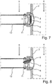
- FIGS 5 and 6 are shown examples of further advantageous developments of the pressure relief device 1 according to the present invention with one or two web or pin-like elements 10, 10 '.
- the Figures 7 and 6 show a view of the pressure relief device 1 in an installed state from the outside onto a battery housing 2.
- This web-like or pin-like element 10 or these web-like or pin-like elements 10, 10 ′ which is or are arranged in a stationary manner with respect to the separating element 3, extends or extend on the side facing the outer region of the separating element 3 parallel to the separating element 3.
- the longitudinal axis of the web-like or pin-like element 10 or of the web-like or pin-like elements 10, 10 ' is aligned with the straight line B. Further, the width of the web-like or pin-like element 10 or web or pin-like elements 10, 10 'smaller than the width of the recess 9 of the plate-shaped element 7.
- the separating element 3 (the bursting membrane) does not bulge out or only so slightly that it cannot be damaged by the web-like or pin-like elements 10, 10 '.
- the holding device 6 and the connecting piece 11 are shown as separate elements.
- the holding device 6 and the connecting piece 11 can also be designed as a common component.
- gases escaping from the battery housing 2, such as occur, for example, when at least one battery cell passes thermally and the separating element 3 is opened, can be defined and discharged into the environment in a targeted manner.
- a battery according to the present invention is characterized in that at least one battery cell is arranged in a battery housing 2 according to the invention or in one of its advantageous developments and refinements.
- the present invention further encompasses not only the method according to claim 9, but also all further developments and refinements thereof, which are readily apparent to a person skilled in the art from the description of the pressure relief device 1, the battery housing 2, the battery, the figure description and the figures.
- the present invention ensures quick and reliable opening of a pressure relief device, which serves as a pressure compensation device during normal operation of a battery, in the event of a thermal event of a battery, in particular a high-voltage battery. This means that a higher level of safety is achieved in a battery during a thermal event.
Landscapes
- Chemical & Material Sciences (AREA)
- Chemical Kinetics & Catalysis (AREA)
- Electrochemistry (AREA)
- General Chemical & Material Sciences (AREA)
- Gas Exhaust Devices For Batteries (AREA)
- Fuel Cell (AREA)
Claims (9)
- Dispositif de décompression (1) pour un boîtier de batterie (2), conçu pour compenser une différence de pression entre une pression interne du boîtier de batterie (2) et une pression ambiante du boîtier de batterie (2) résultant du passage thermique d'au moins une cellule de batterie, le dispositif de décompression (1) comprenant :- un élément de séparation (3) destiné à séparer une zone intérieure (4) du boîtier de batterie (2) d'une zone extérieure (5) du boîtier de batterie (2), l'élément de séparation (3) étant conçu de telle manière qu'il se dilate et se déforme en cas de différence de pression prédéterminable entre la pression intérieure du boîtier de batterie (2) et la pression ambiante du boîtier de batterie (2),- un élément de retenue (6) pour l'élément de séparation (3), destiné à la fixation mécanique de l'élément de séparation (3) au boîtier de batterie (2), et- un élément (7) en forme de plaque qui est disposé, dans un état incorporé, du côté de l'élément de séparation (3) qui est dirigé vers la zone intérieure (4) du boîtier de batterie (2), parallèlement à l'élément de séparation (3)
caractérisé en ce que l'élément (7) en forme de plaquea) est accouplé mécaniquement à l'élément de retenue (6) par l'intermédiaire d'un élément jointif (8) déformable plastiquement ou élastiquement et comporte un évidement rectiligne (9) qui s'étend à l'intérieur de l'élément (7) en forme de plaque à partir d'une distance prédéterminable de l'élément jointif (8) transversalement à un axe de basculement A défini à travers l'élément jointif (8) au centre d'une ligne droite B à travers l'élément (7) en forme de plaque, et se termine à une distance prédéterminable du bord fermé de l'élément (7) en forme de plaque opposé à l'élément jointif (8) ; oub) est accouplé mécaniquement à l'élément de retenue (6) par l'intermédiaire d'un premier (8) et d'un second élément jointif (8') déformable plastiquement ou élastiquement, les deux éléments jointifs (8, 8') étant disposés de manière opposée l'un à l'autre et au centre d'une ligne droite B s'étendant à travers le centre de l'élément (7) en forme de plaque, et comporte un évidement rectiligne (9) dont l'axe longitudinal est aligné avec la ligne droite B et qui s'étend à l'intérieur de l'élément (7) en forme de plaque d'une distance prédéterminable du premier élément jointif (8) jusqu'à une distance prédéterminable du second élément jointif (8'). - Dispositif de décompression (1) selon la revendication 1, caractérisé en ce que le dispositif de décompression (1) comporte un ou deux éléments (10, 10') en forme de barre ou de tige qui sont disposés dans une position fixe par rapport à l'élément de séparation (3), lesquels éléments s'étendent, dans un état incorporé, parallèlement à l'élément de séparation (3) du côté de l'élément de séparation (3) dirigé vers la zone extérieure (5) du boîtier de batterie (2), dont l'axe longitudinal est aligné avec la ligne droite B et dont la largeur est inférieure à la largeur de l'évidement (9) de l'élément (7) en forme de plaque.
- Dispositif de décompression (1) selon la revendication 1 ou 2, caractérisé en ce que l'élément (7) en forme de plaque présente une forme ronde, de préférence une forme elliptique, en particulier une forme circulaire.
- Dispositif de décompression (1) selon l'une des revendications précédentes, caractérisé en ce que l'élément de séparation (3) est formé par une membrane, en particulier une membrane poreuse qui est conçue pour permettre le passage de gaz entre la zone intérieure (4) et la zone extérieure (5) d'un boîtier de batterie (2).
- Boîtier de batterie (2) destiné à recevoir au moins un élément de batterie, caractérisé en ce qu'au moins une paroi du boîtier de batterie comporte un dispositif de décompression (1) selon l'une des revendications 1 à 4.
- Boîtier de batterie (2) selon la revendication 5, caractérisé en ce qu'il- comporte un raccord (11) destiné à relier un tuyau d'échappement (12) pour évacuer les gaz s'échappant du boîtier de batterie (2), une liaison fluidique étant prévue entre le raccord (11) et le dispositif de décompression (1).
- Boîtier de batterie (2) selon la revendication 6, caractérisé en ce qu'il comporte un tuyau d'échappement (12) relié au raccord (11) pour évacuer les gaz s'échappant du boîtier de batterie (2).
- Batterie comprenant au moins une cellule de batterie, caractérisée en ce que ladite au moins une cellule de batterie est disposée dans un boîtier de batterie (2) selon l'une des revendications 5 à 7.
- Procédé de décompression d'une batterie selon la revendication 8, à partir d'une surpression prédéterminable résultant du passage thermique d'au moins une cellule de batterie dans la zone intérieure (4) du boîtier de batterie (2) par rapport à la pression ambiante du boîtier de batterie (2), comprenant les étapes :- de fourniture d'une batterie présentant les caractéristiques selon la revendication 8, et-- de basculement de l'élément (7) en forme de plaque, lequel est accouplé mécaniquement à l'élément de retenue (6) par l'intermédiaire d'un élément jointif (8) déformable plastiquement ou élastiquement, à partir d'une pression dynamique prédéterminable se produisant sur l'élément (7) en forme de plaque autour d'un axe de basculement A défini par l'élément jointif (8) dans la direction de l'élément de séparation (3), et de formation d'une fissure dans l'élément de séparation (3) le long d'un bord de l'élément (7) en forme de plaque, lequel bord de l'élément est pénétré dans la surface de l'élément de séparation (3), afin d'évacuer la surpression, ou-- de basculement des côtés libres de l'élément (7) en forme de plaque, lequel est accouplé mécaniquement à l'élément de retenue (6) par l'intermédiaire d'un premier (8) et d'un second élément jointif (8') déformable plastiquement ou élastiquement, à partir d'une pression dynamique prédéterminable se produisant sur l'élément (7) en forme de plaque autour de l'axe de basculement formé par la droite B dans la direction de l'élément de séparation (3), et de formation d'une fissure dans l'élément de séparation (3) le long de chacun des deux bords de l'élément (7) en forme de plaque qui sont pénétrés dans la surface de l'élément de séparation (3), afin d'évacuer la surpression.
Applications Claiming Priority (2)
| Application Number | Priority Date | Filing Date | Title |
|---|---|---|---|
| DE102016004648.1A DE102016004648A1 (de) | 2016-04-16 | 2016-04-16 | Druckentlastungsvorrichtung für ein Batteriegehäuse, Batteriegehäuse mit der Druckentlastungsvorrichtung, Batterie sowie Verfahren zur Druckentlastung einer Batterie |
| PCT/EP2017/058879 WO2017178564A1 (fr) | 2016-04-16 | 2017-04-12 | Dispositif de décompression pour boîtier de batterie, boîtier de batterie muni du dispositif de décompression, batterie et procédé de décompression de batterie |
Publications (2)
| Publication Number | Publication Date |
|---|---|
| EP3443603A1 EP3443603A1 (fr) | 2019-02-20 |
| EP3443603B1 true EP3443603B1 (fr) | 2020-03-18 |
Family
ID=58537024
Family Applications (1)
| Application Number | Title | Priority Date | Filing Date |
|---|---|---|---|
| EP17716922.4A Active EP3443603B1 (fr) | 2016-04-16 | 2017-04-12 | Dispositif de détente de pression pour un boitier de batterie, boitier de batterie avec dispositif de détente de pression, batterie, et procede de détente de pression d'une batterie |
Country Status (4)
| Country | Link |
|---|---|
| EP (1) | EP3443603B1 (fr) |
| CN (1) | CN109564989B (fr) |
| DE (1) | DE102016004648A1 (fr) |
| WO (1) | WO2017178564A1 (fr) |
Cited By (1)
| Publication number | Priority date | Publication date | Assignee | Title |
|---|---|---|---|---|
| US12476322B2 (en) | 2023-10-10 | 2025-11-18 | Ford Global Technologies, Llc | Battery pack venting assembly and venting method |
Families Citing this family (10)
| Publication number | Priority date | Publication date | Assignee | Title |
|---|---|---|---|---|
| DE102018210975B4 (de) * | 2018-07-04 | 2021-02-04 | Bayerische Motoren Werke Aktiengesellschaft | Batteriemanagementsystem für eine Hochvoltbatterie eines Kraftfahrzeugs, Hochvoltbatterie sowie Kraftfahrzeug |
| DE202019106891U1 (de) | 2019-12-11 | 2020-12-16 | Hugo Benzing Gmbh & Co. Kg | Druckentlastungsvorrichtung |
| DE102020101756B4 (de) | 2020-01-24 | 2023-07-27 | Hugo Benzing Gmbh & Co. Kg | Berstschutzeinheit |
| DE102020108442A1 (de) * | 2020-03-26 | 2021-09-30 | Kautex Textron Gmbh & Co. Kg | Batterieschale, Traktionsbatterie, Kraftfahrzeug und Verfahren zum Herstellen einer Batterieschale |
| DE102020112565B4 (de) | 2020-05-08 | 2024-06-13 | Hugo Benzing Gmbh & Co. Kg | Druckentlastungsventil |
| DE102020209759A1 (de) * | 2020-08-03 | 2022-02-03 | Volkswagen Aktiengesellschaft | Hochvoltzelle |
| DE202020105592U1 (de) | 2020-09-30 | 2021-10-01 | Hugo Benzing Gmbh & Co. Kg | Berstschutzabdeckung für einen Behälter |
| FR3116239A1 (fr) * | 2020-11-17 | 2022-05-20 | Psa Automobiles Sa | Capuchon destructible pour un ecran de protection d’une batterie |
| US12537261B2 (en) | 2022-08-15 | 2026-01-27 | Ford Global Technologies, Llc | Traction battery pack venting assembly and venting method |
| FR3161073B1 (fr) * | 2024-04-03 | 2026-05-01 | Accumulateurs Fixes | Ensemble de batterie et véhicule correspondant |
Family Cites Families (12)
| Publication number | Priority date | Publication date | Assignee | Title |
|---|---|---|---|---|
| JPH03226964A (ja) * | 1990-01-31 | 1991-10-07 | Seiko Electronic Components Ltd | 安全弁付電池 |
| JP3551263B2 (ja) * | 1993-10-08 | 2004-08-04 | 株式会社指月電機製作所 | 安全装置 |
| KR100202928B1 (ko) * | 1996-03-30 | 1999-06-15 | 전주범 | 유기 전해액 전지용 안전장치 |
| US6696196B1 (en) * | 1999-08-18 | 2004-02-24 | Itt Manufacturing Enterprises, Inc. | Closed battery container having high volume rapid venting feature |
| WO2002059990A2 (fr) * | 2000-11-21 | 2002-08-01 | The Gillette Company | Event de pile |
| US6855454B2 (en) * | 2001-12-20 | 2005-02-15 | Eveready Battery Company, Inc. | Electrochemical cell having venting current collector and seal assembly |
| US7195839B2 (en) * | 2003-02-11 | 2007-03-27 | Eveready Battery Company, Inc. | Battery cell with improved pressure relief vent |
| WO2013038273A2 (fr) * | 2011-09-16 | 2013-03-21 | Paul Goggin | Disque de rupture et articulation |
| US9871235B2 (en) * | 2011-11-16 | 2018-01-16 | Johnson Controls Advanced Power Solutions Gmbh | Pressure relief element, pressure relief device and battery |
| CN203081514U (zh) * | 2013-01-25 | 2013-07-24 | 潍坊雷诺特动力设备有限公司 | 汽轮机真空保护装置 |
| DE102014017232A1 (de) | 2014-11-20 | 2015-06-18 | Daimler Ag | Batteriegehäuseanordnung mit einem plattenförmigen Element für ein Kraftfahrzeug und Verfahren zur Druckentlastung einer derartigen Batteriegehäuseanordnung |
| DE102014017233A1 (de) * | 2014-11-20 | 2015-06-11 | Daimler Ag | Batteriegehäuseanordnung mit einem Trennelement mit partiell verstärkter Oberfläche für ein Kraftfahrzeug und Verfahren zur Druckentlastung einer derartigen Batteriegehäuseanordnung |
-
2016
- 2016-04-16 DE DE102016004648.1A patent/DE102016004648A1/de active Pending
-
2017
- 2017-04-12 CN CN201780034303.7A patent/CN109564989B/zh active Active
- 2017-04-12 WO PCT/EP2017/058879 patent/WO2017178564A1/fr not_active Ceased
- 2017-04-12 EP EP17716922.4A patent/EP3443603B1/fr active Active
Non-Patent Citations (1)
| Title |
|---|
| None * |
Cited By (1)
| Publication number | Priority date | Publication date | Assignee | Title |
|---|---|---|---|---|
| US12476322B2 (en) | 2023-10-10 | 2025-11-18 | Ford Global Technologies, Llc | Battery pack venting assembly and venting method |
Also Published As
| Publication number | Publication date |
|---|---|
| CN109564989B (zh) | 2021-09-21 |
| WO2017178564A1 (fr) | 2017-10-19 |
| CN109564989A (zh) | 2019-04-02 |
| EP3443603A1 (fr) | 2019-02-20 |
| DE102016004648A1 (de) | 2017-10-19 |
Similar Documents
| Publication | Publication Date | Title |
|---|---|---|
| WO2017178564A1 (fr) | Dispositif de décompression pour boîtier de batterie, boîtier de batterie muni du dispositif de décompression, batterie et procédé de décompression de batterie | |
| DE112012006312B4 (de) | Abgedichtete Sekundärbatterie | |
| EP2532039B1 (fr) | Élément de batterie présentant une soupape de sûreté pour la ventilation et procédé de production d'une soupape de sûreté dans un boîtier de batterie | |
| EP2732485B1 (fr) | Module de cellules de batterie, procédé de fonctionnement d'un module de cellules de batterie ainsi que batterie et véhicule | |
| DE102008059956B4 (de) | Batterie, insbesondere Fahrzeugbatterie | |
| DE102021132479A1 (de) | Batterieanordnung und Verfahren zum Abführen eines Gases aus einer Batteriezelle | |
| EP2606520B1 (fr) | Cellule électrochimique avec au moins un dispositif de décompression | |
| DE102019118905A1 (de) | Kühlsystem und Energiespeicher mit einem Kühlsystem | |
| EP2486612A1 (fr) | Cellule électrochimique | |
| EP4256639A1 (fr) | Ensemble unité de dégazage, unité de dégazage, utilisation d'une unité de dégazage dans un ensemble de dégazage, et boîtier de batterie | |
| EP2994949B1 (fr) | Batterie comprenant un dispositif de sécurité pouvant être réarmé ainsi que boulons de borne appropriés pour ladite batterie | |
| DE102014208062A1 (de) | Batteriesystem mit einer Mehrzahl von Batteriezellen und einer Entgasungseinrichtung | |
| DE102013014929A1 (de) | Batterie, insbesondere für den Einsatz in elektromotorisch angetriebenen Fahrzeugen sowie Fahrzeug mit einer solchen Batterie | |
| DE102012222870A1 (de) | Energiespeicher mit Sicherheitsventil | |
| EP4648183A1 (fr) | Boîtier d'élément pour corps d'élément de batterie | |
| DE102017208842B4 (de) | Speichereinrichtung zum Speichern von elektrischer Energie, insbesondere für ein Kraftfahrzeug, Kraftfahrzeug mit einer solchen Speichereinrichtung, sowie Verfahren zum Betreiben einer solchen Speichereinrichtung | |
| DE102018109328A1 (de) | Batterieeinheit mit einem Batteriegehäuse, mindestens einem, in diesem Batteriegehäuse angeordneten Zellverbund und mindestens einem Zellmanagement-Controller sowie Verfahren zur Herstellung einer solchen Batterieeinheit | |
| DE102020118846A1 (de) | Batteriezelle und Batteriemodul | |
| DE102014017232A1 (de) | Batteriegehäuseanordnung mit einem plattenförmigen Element für ein Kraftfahrzeug und Verfahren zur Druckentlastung einer derartigen Batteriegehäuseanordnung | |
| DE102008059958A1 (de) | Batterie, insbesondere Fahrzeugbatterie | |
| DE102022106343A1 (de) | Energiespeicheranordnung für ein Kraftfahrzeug und Verfahren zum Herstellen einer Energiespeicheranordnung | |
| EP3082179A1 (fr) | Batterie avec commutateur de securite electropneumatique | |
| DE102023105038A1 (de) | Elektrischer Energiespeicher für ein Kraftfahrzeug, Kraftfahrzeug sowie Verfahren zum Herstellen eines solchen elektrischen Energiespeichers | |
| DE102024109554B3 (de) | Zelltrennelement mit Halterung, Batterieanordnung und Verfahren zum Herstellen eines Zelltrennelements | |
| DE102014202337A1 (de) | Gehäuse mit verbesserter Wärmeleitung |
Legal Events
| Date | Code | Title | Description |
|---|---|---|---|
| STAA | Information on the status of an ep patent application or granted ep patent |
Free format text: STATUS: UNKNOWN |
|
| STAA | Information on the status of an ep patent application or granted ep patent |
Free format text: STATUS: THE INTERNATIONAL PUBLICATION HAS BEEN MADE |
|
| PUAI | Public reference made under article 153(3) epc to a published international application that has entered the european phase |
Free format text: ORIGINAL CODE: 0009012 |
|
| STAA | Information on the status of an ep patent application or granted ep patent |
Free format text: STATUS: REQUEST FOR EXAMINATION WAS MADE |
|
| 17P | Request for examination filed |
Effective date: 20181116 |
|
| AK | Designated contracting states |
Kind code of ref document: A1 Designated state(s): AL AT BE BG CH CY CZ DE DK EE ES FI FR GB GR HR HU IE IS IT LI LT LU LV MC MK MT NL NO PL PT RO RS SE SI SK SM TR |
|
| AX | Request for extension of the european patent |
Extension state: BA ME |
|
| DAV | Request for validation of the european patent (deleted) | ||
| DAX | Request for extension of the european patent (deleted) | ||
| GRAP | Despatch of communication of intention to grant a patent |
Free format text: ORIGINAL CODE: EPIDOSNIGR1 |
|
| STAA | Information on the status of an ep patent application or granted ep patent |
Free format text: STATUS: GRANT OF PATENT IS INTENDED |
|
| INTG | Intention to grant announced |
Effective date: 20191114 |
|
| GRAS | Grant fee paid |
Free format text: ORIGINAL CODE: EPIDOSNIGR3 |
|
| GRAA | (expected) grant |
Free format text: ORIGINAL CODE: 0009210 |
|
| STAA | Information on the status of an ep patent application or granted ep patent |
Free format text: STATUS: THE PATENT HAS BEEN GRANTED |
|
| AK | Designated contracting states |
Kind code of ref document: B1 Designated state(s): AL AT BE BG CH CY CZ DE DK EE ES FI FR GB GR HR HU IE IS IT LI LT LU LV MC MK MT NL NO PL PT RO RS SE SI SK SM TR |
|
| REG | Reference to a national code |
Ref country code: GB Ref legal event code: FG4D Free format text: NOT ENGLISH |
|
| REG | Reference to a national code |
Ref country code: DE Ref legal event code: R096 Ref document number: 502017004301 Country of ref document: DE |
|
| REG | Reference to a national code |
Ref country code: AT Ref legal event code: REF Ref document number: 1246955 Country of ref document: AT Kind code of ref document: T Effective date: 20200415 Ref country code: IE Ref legal event code: FG4D Free format text: LANGUAGE OF EP DOCUMENT: GERMAN |
|
| PG25 | Lapsed in a contracting state [announced via postgrant information from national office to epo] |
Ref country code: FI Free format text: LAPSE BECAUSE OF FAILURE TO SUBMIT A TRANSLATION OF THE DESCRIPTION OR TO PAY THE FEE WITHIN THE PRESCRIBED TIME-LIMIT Effective date: 20200318 Ref country code: RS Free format text: LAPSE BECAUSE OF FAILURE TO SUBMIT A TRANSLATION OF THE DESCRIPTION OR TO PAY THE FEE WITHIN THE PRESCRIBED TIME-LIMIT Effective date: 20200318 Ref country code: NO Free format text: LAPSE BECAUSE OF FAILURE TO SUBMIT A TRANSLATION OF THE DESCRIPTION OR TO PAY THE FEE WITHIN THE PRESCRIBED TIME-LIMIT Effective date: 20200618 |
|
| REG | Reference to a national code |
Ref country code: NL Ref legal event code: MP Effective date: 20200318 |
|
| PG25 | Lapsed in a contracting state [announced via postgrant information from national office to epo] |
Ref country code: BG Free format text: LAPSE BECAUSE OF FAILURE TO SUBMIT A TRANSLATION OF THE DESCRIPTION OR TO PAY THE FEE WITHIN THE PRESCRIBED TIME-LIMIT Effective date: 20200618 Ref country code: SE Free format text: LAPSE BECAUSE OF FAILURE TO SUBMIT A TRANSLATION OF THE DESCRIPTION OR TO PAY THE FEE WITHIN THE PRESCRIBED TIME-LIMIT Effective date: 20200318 Ref country code: HR Free format text: LAPSE BECAUSE OF FAILURE TO SUBMIT A TRANSLATION OF THE DESCRIPTION OR TO PAY THE FEE WITHIN THE PRESCRIBED TIME-LIMIT Effective date: 20200318 Ref country code: LV Free format text: LAPSE BECAUSE OF FAILURE TO SUBMIT A TRANSLATION OF THE DESCRIPTION OR TO PAY THE FEE WITHIN THE PRESCRIBED TIME-LIMIT Effective date: 20200318 Ref country code: GR Free format text: LAPSE BECAUSE OF FAILURE TO SUBMIT A TRANSLATION OF THE DESCRIPTION OR TO PAY THE FEE WITHIN THE PRESCRIBED TIME-LIMIT Effective date: 20200619 |
|
| REG | Reference to a national code |
Ref country code: LT Ref legal event code: MG4D |
|
| PG25 | Lapsed in a contracting state [announced via postgrant information from national office to epo] |
Ref country code: NL Free format text: LAPSE BECAUSE OF FAILURE TO SUBMIT A TRANSLATION OF THE DESCRIPTION OR TO PAY THE FEE WITHIN THE PRESCRIBED TIME-LIMIT Effective date: 20200318 |
|
| PG25 | Lapsed in a contracting state [announced via postgrant information from national office to epo] |
Ref country code: LT Free format text: LAPSE BECAUSE OF FAILURE TO SUBMIT A TRANSLATION OF THE DESCRIPTION OR TO PAY THE FEE WITHIN THE PRESCRIBED TIME-LIMIT Effective date: 20200318 Ref country code: SK Free format text: LAPSE BECAUSE OF FAILURE TO SUBMIT A TRANSLATION OF THE DESCRIPTION OR TO PAY THE FEE WITHIN THE PRESCRIBED TIME-LIMIT Effective date: 20200318 Ref country code: IS Free format text: LAPSE BECAUSE OF FAILURE TO SUBMIT A TRANSLATION OF THE DESCRIPTION OR TO PAY THE FEE WITHIN THE PRESCRIBED TIME-LIMIT Effective date: 20200718 Ref country code: RO Free format text: LAPSE BECAUSE OF FAILURE TO SUBMIT A TRANSLATION OF THE DESCRIPTION OR TO PAY THE FEE WITHIN THE PRESCRIBED TIME-LIMIT Effective date: 20200318 Ref country code: CZ Free format text: LAPSE BECAUSE OF FAILURE TO SUBMIT A TRANSLATION OF THE DESCRIPTION OR TO PAY THE FEE WITHIN THE PRESCRIBED TIME-LIMIT Effective date: 20200318 Ref country code: SM Free format text: LAPSE BECAUSE OF FAILURE TO SUBMIT A TRANSLATION OF THE DESCRIPTION OR TO PAY THE FEE WITHIN THE PRESCRIBED TIME-LIMIT Effective date: 20200318 Ref country code: EE Free format text: LAPSE BECAUSE OF FAILURE TO SUBMIT A TRANSLATION OF THE DESCRIPTION OR TO PAY THE FEE WITHIN THE PRESCRIBED TIME-LIMIT Effective date: 20200318 Ref country code: PT Free format text: LAPSE BECAUSE OF FAILURE TO SUBMIT A TRANSLATION OF THE DESCRIPTION OR TO PAY THE FEE WITHIN THE PRESCRIBED TIME-LIMIT Effective date: 20200812 |
|
| REG | Reference to a national code |
Ref country code: DE Ref legal event code: R079 Ref document number: 502017004301 Country of ref document: DE Free format text: PREVIOUS MAIN CLASS: H01M0002020000 Ipc: H01M0050100000 |
|
| REG | Reference to a national code |
Ref country code: CH Ref legal event code: PL |
|
| REG | Reference to a national code |
Ref country code: DE Ref legal event code: R097 Ref document number: 502017004301 Country of ref document: DE |
|
| PG25 | Lapsed in a contracting state [announced via postgrant information from national office to epo] |
Ref country code: MC Free format text: LAPSE BECAUSE OF FAILURE TO SUBMIT A TRANSLATION OF THE DESCRIPTION OR TO PAY THE FEE WITHIN THE PRESCRIBED TIME-LIMIT Effective date: 20200318 |
|
| PLBE | No opposition filed within time limit |
Free format text: ORIGINAL CODE: 0009261 |
|
| STAA | Information on the status of an ep patent application or granted ep patent |
Free format text: STATUS: NO OPPOSITION FILED WITHIN TIME LIMIT |
|
| PG25 | Lapsed in a contracting state [announced via postgrant information from national office to epo] |
Ref country code: IT Free format text: LAPSE BECAUSE OF FAILURE TO SUBMIT A TRANSLATION OF THE DESCRIPTION OR TO PAY THE FEE WITHIN THE PRESCRIBED TIME-LIMIT Effective date: 20200318 Ref country code: CH Free format text: LAPSE BECAUSE OF NON-PAYMENT OF DUE FEES Effective date: 20200430 Ref country code: LI Free format text: LAPSE BECAUSE OF NON-PAYMENT OF DUE FEES Effective date: 20200430 Ref country code: DK Free format text: LAPSE BECAUSE OF FAILURE TO SUBMIT A TRANSLATION OF THE DESCRIPTION OR TO PAY THE FEE WITHIN THE PRESCRIBED TIME-LIMIT Effective date: 20200318 Ref country code: LU Free format text: LAPSE BECAUSE OF NON-PAYMENT OF DUE FEES Effective date: 20200412 Ref country code: ES Free format text: LAPSE BECAUSE OF FAILURE TO SUBMIT A TRANSLATION OF THE DESCRIPTION OR TO PAY THE FEE WITHIN THE PRESCRIBED TIME-LIMIT Effective date: 20200318 |
|
| REG | Reference to a national code |
Ref country code: BE Ref legal event code: MM Effective date: 20200430 |
|
| 26N | No opposition filed |
Effective date: 20201221 |
|
| PG25 | Lapsed in a contracting state [announced via postgrant information from national office to epo] |
Ref country code: PL Free format text: LAPSE BECAUSE OF FAILURE TO SUBMIT A TRANSLATION OF THE DESCRIPTION OR TO PAY THE FEE WITHIN THE PRESCRIBED TIME-LIMIT Effective date: 20200318 Ref country code: BE Free format text: LAPSE BECAUSE OF NON-PAYMENT OF DUE FEES Effective date: 20200430 |
|
| PG25 | Lapsed in a contracting state [announced via postgrant information from national office to epo] |
Ref country code: IE Free format text: LAPSE BECAUSE OF NON-PAYMENT OF DUE FEES Effective date: 20200412 Ref country code: FR Free format text: LAPSE BECAUSE OF NON-PAYMENT OF DUE FEES Effective date: 20200518 |
|
| PG25 | Lapsed in a contracting state [announced via postgrant information from national office to epo] |
Ref country code: SI Free format text: LAPSE BECAUSE OF FAILURE TO SUBMIT A TRANSLATION OF THE DESCRIPTION OR TO PAY THE FEE WITHIN THE PRESCRIBED TIME-LIMIT Effective date: 20200318 |
|
| GBPC | Gb: european patent ceased through non-payment of renewal fee |
Effective date: 20210412 |
|
| PG25 | Lapsed in a contracting state [announced via postgrant information from national office to epo] |
Ref country code: GB Free format text: LAPSE BECAUSE OF NON-PAYMENT OF DUE FEES Effective date: 20210412 |
|
| PG25 | Lapsed in a contracting state [announced via postgrant information from national office to epo] |
Ref country code: TR Free format text: LAPSE BECAUSE OF FAILURE TO SUBMIT A TRANSLATION OF THE DESCRIPTION OR TO PAY THE FEE WITHIN THE PRESCRIBED TIME-LIMIT Effective date: 20200318 Ref country code: MT Free format text: LAPSE BECAUSE OF FAILURE TO SUBMIT A TRANSLATION OF THE DESCRIPTION OR TO PAY THE FEE WITHIN THE PRESCRIBED TIME-LIMIT Effective date: 20200318 Ref country code: CY Free format text: LAPSE BECAUSE OF FAILURE TO SUBMIT A TRANSLATION OF THE DESCRIPTION OR TO PAY THE FEE WITHIN THE PRESCRIBED TIME-LIMIT Effective date: 20200318 |
|
| PG25 | Lapsed in a contracting state [announced via postgrant information from national office to epo] |
Ref country code: MK Free format text: LAPSE BECAUSE OF FAILURE TO SUBMIT A TRANSLATION OF THE DESCRIPTION OR TO PAY THE FEE WITHIN THE PRESCRIBED TIME-LIMIT Effective date: 20200318 Ref country code: AL Free format text: LAPSE BECAUSE OF FAILURE TO SUBMIT A TRANSLATION OF THE DESCRIPTION OR TO PAY THE FEE WITHIN THE PRESCRIBED TIME-LIMIT Effective date: 20200318 |
|
| REG | Reference to a national code |
Ref country code: AT Ref legal event code: MM01 Ref document number: 1246955 Country of ref document: AT Kind code of ref document: T Effective date: 20220412 |
|
| PG25 | Lapsed in a contracting state [announced via postgrant information from national office to epo] |
Ref country code: AT Free format text: LAPSE BECAUSE OF NON-PAYMENT OF DUE FEES Effective date: 20220412 |
|
| PGFP | Annual fee paid to national office [announced via postgrant information from national office to epo] |
Ref country code: DE Payment date: 20250422 Year of fee payment: 9 |