EP3443699B1 - Gemeinsamen phasenfehler-korrektur - Google Patents
Gemeinsamen phasenfehler-korrektur Download PDFInfo
- Publication number
- EP3443699B1 EP3443699B1 EP16766100.8A EP16766100A EP3443699B1 EP 3443699 B1 EP3443699 B1 EP 3443699B1 EP 16766100 A EP16766100 A EP 16766100A EP 3443699 B1 EP3443699 B1 EP 3443699B1
- Authority
- EP
- European Patent Office
- Prior art keywords
- cpe
- code
- wireless
- symbol
- length
- Prior art date
- Legal status (The legal status is an assumption and is not a legal conclusion. Google has not performed a legal analysis and makes no representation as to the accuracy of the status listed.)
- Active
Links
Images



Classifications
-
- H—ELECTRICITY
- H04—ELECTRIC COMMUNICATION TECHNIQUE
- H04B—TRANSMISSION
- H04B1/00—Details of transmission systems, not covered by a single one of groups H04B3/00 - H04B13/00; Details of transmission systems not characterised by the medium used for transmission
- H04B1/06—Receivers
- H04B1/10—Means associated with receiver for limiting or suppressing noise or interference
- H04B1/12—Neutralising, balancing, or compensation arrangements
-
- H—ELECTRICITY
- H04—ELECTRIC COMMUNICATION TECHNIQUE
- H04L—TRANSMISSION OF DIGITAL INFORMATION, e.g. TELEGRAPHIC COMMUNICATION
- H04L5/00—Arrangements affording multiple use of the transmission path
- H04L5/003—Arrangements for allocating sub-channels of the transmission path
- H04L5/0048—Allocation of pilot signals, i.e. of signals known to the receiver
- H04L5/0051—Allocation of pilot signals, i.e. of signals known to the receiver of dedicated pilots, i.e. pilots destined for a single user or terminal
-
- H—ELECTRICITY
- H04—ELECTRIC COMMUNICATION TECHNIQUE
- H04J—MULTIPLEX COMMUNICATION
- H04J13/00—Code division multiplex systems
- H04J13/0007—Code type
- H04J13/004—Orthogonal
- H04J13/0048—Walsh
-
- H—ELECTRICITY
- H04—ELECTRIC COMMUNICATION TECHNIQUE
- H04L—TRANSMISSION OF DIGITAL INFORMATION, e.g. TELEGRAPHIC COMMUNICATION
- H04L25/00—Baseband systems
- H04L25/02—Details ; arrangements for supplying electrical power along data transmission lines
- H04L25/0202—Channel estimation
- H04L25/0224—Channel estimation using sounding signals
- H04L25/0226—Channel estimation using sounding signals sounding signals per se
-
- H—ELECTRICITY
- H04—ELECTRIC COMMUNICATION TECHNIQUE
- H04L—TRANSMISSION OF DIGITAL INFORMATION, e.g. TELEGRAPHIC COMMUNICATION
- H04L27/00—Modulated-carrier systems
- H04L27/26—Systems using multi-frequency codes
- H04L27/2601—Multicarrier modulation systems
- H04L27/2647—Arrangements specific to the receiver only
- H04L27/2655—Synchronisation arrangements
- H04L27/2668—Details of algorithms
- H04L27/2673—Details of algorithms characterised by synchronisation parameters
- H04L27/2675—Pilot or known symbols
-
- H—ELECTRICITY
- H04—ELECTRIC COMMUNICATION TECHNIQUE
- H04L—TRANSMISSION OF DIGITAL INFORMATION, e.g. TELEGRAPHIC COMMUNICATION
- H04L5/00—Arrangements affording multiple use of the transmission path
- H04L5/02—Channels characterised by the type of signal
- H04L5/023—Multiplexing of multicarrier modulation signals, e.g. multi-user orthogonal frequency division multiple access [OFDMA]
- H04L5/026—Multiplexing of multicarrier modulation signals, e.g. multi-user orthogonal frequency division multiple access [OFDMA] using code division
-
- H—ELECTRICITY
- H04—ELECTRIC COMMUNICATION TECHNIQUE
- H04J—MULTIPLEX COMMUNICATION
- H04J11/00—Orthogonal multiplex systems, e.g. using WALSH codes
- H04J2011/0003—Combination with other multiplexing techniques
- H04J2011/0016—Combination with other multiplexing techniques with FDM/FDMA and TDM/TDMA
Definitions
- Particular embodiments relate generally to error compensation in a wireless communication network, and more particularly to a common phase error reference signal.
- Communications between a wireless transmitter and receiver generally require synchronization in time and/or frequency to facilitate reliable reception of messages.
- cellular systems such as Third Generation Partnership Project (3GPP) long term evolution (LTE) or LTE New Radio (LTE NR, LTE-NX, or LTE 5G)
- LTE long term evolution
- LTE NR, LTE-NX, or LTE 5G base stations broadcast narrowband synchronization signals (PSS/SSS) regularly in time. From the synchronization signals, wireless devices accessing the system can perform an initial cell search (i.e., a synchronization procedure that includes finding carrier frequencies, time reference instants and cell identities).
- An LTE device that has performed initial cell search and identified the cell identity can then complete the initial synchronization in downlink by making a fine synchronization on cell specific reference signals (CRS).
- CRS are transmitted over the system bandwidth more frequently in time than the synchronization signals.
- the device connects to the network via a random access procedure in which uplink time synchronization will be established and communications between the device and the base station can begin. Oscillator drifting at both transmitter and receiver sides may cause a wireless device to regularly perform fine frequency synchronization in downlink during communications with a base station.
- LTE-NX includes a lean frame structure design without cell specific reference signals (CRS). Reference signals required for fine synchronization and demodulation of a downlink (DL) physical data channel (PDCH) are embedded into the PDCH transmission.
- DL downlink
- PDCH physical data channel
- FIGURE 1 An example of a PDCH downlink transmissions and its associated downlink control channel (PDCCH), carrying an assignment or a grant, is illustrated in FIGURE 1 .
- FIGURE 1 is a block diagram illustrating downlink transmissions of physical data channel and associated physical downlink control channel.
- Two radio subframes 10 each include four orthogonal frequency division multiplexed (OFDM) symbols 12.
- the first OFDM symbol 12 of each subframe 10 includes PDCCH 14 and the following OFDM symbols 12 include PDCHs 16.
- transmissions of PDCH 16 may span over multiple subframes 10 using subframe aggregation (e.g., PDCH 16a) or be confined to one subframe 10 (e.g., PDCH 16b).
- a wireless device also referred to as user equipment (UE) detects PDCCH addressed to the wireless device. From the scheduling information in the PDCCH, the wireless device derives PDCH related information.
- a UE is not aware of PDCCH transmissions to other UEs where a PDCCH to one particular user is carried on a subset of OFDM subcarriers.
- the mapping of PDCCH can either be distributed or localized.
- FIGURE 1 illustrates the latter.
- the number of OFDM symbols within a subframe is a system design parameter and may be larger than the four subframes in the illustrated example.
- PDCCH and PDCH include reference signals for demodulation, generally referred to as demodulation reference signals (DMRS), but other types of reference signals may be referred to herein.
- DMRS demodulation reference signals
- the DMRS is generally transmitted early in the subframe to enable the receiver to perform early channel estimation and thus reduce receiver processing.
- LTE-NX performs time-synchronization using a first reference signal (e.g., Time Synchronization Signal (TSS)) and coarse-frequency-synchronization using the same first reference signal or a second signal (e.g., Frequency Synchronization Signal (FSS)).
- TSS Time Synchronization Signal
- FSS Frequency Synchronization Signal
- These signals generally do not provide highly accurate synchronization, either in time or in frequency.
- the time-error may be handled by the cyclic-prefix in an OFDM system, and the frequency error may be handled through sufficient sub-carrier spacing.
- Conventional solutions e.g., as in LTE use demodulation reference signals for this purpose (e.g., DMRS or CRS).
- the radio link exhibits some new properties compared to, for example, an LTE system deployed at lower carrier frequencies.
- One new property is that the common phase error scales with the carrier frequency, which introduces a need for a phase reference signal to mitigate a phase error that is common for all subcarriers within an OFDM symbol.
- Such a reference signal may be used both in uplink and downlink, and may be used for both fine carrier frequency-synchronization and for common phase error compensation.
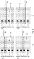
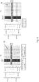
- An example of a common phase error reference signal (CPE-RS) is illustrated in FIGURE 2 .
- FIGURE 2 illustrates example time-frequency grids containing common phase error reference signals (CPE-RS) and demodulation reference signals (DM-RS).
- CPE-RS phase error reference signals
- DM-RS demodulation reference signals
- Each grid comprises time/frequency resources 22.
- the horizontal axis represents time and the vertical axis represents frequency.
- Each grid includes DM-RS 24 and CPE-RS 26.
- CPE-RS 26 is transmitted time continuously and a length-8 cover code is used to create 8 orthogonal DM-RS 24 resources.
- DM-RS 24 resources may be enumerated 0-7 and may refer to 8 DM-RS ports.
- four CPE-RS 26 are allocated to support tracking of common phase errors originating from four different transmitters (e.g., CPE-RS 0, 1, 2, 3).
- CPE-RS 26 is transmitted jointly with DM-RS 24 (and thus with the data channel PDCH) on a subset of the subcarriers allocated for DM-RS 24.
- DM-RS 24 may be transmitted in one (or a few) OFDM symbols early within a subframe, or within a subframe aggregation, whereas CPE-RS 26 may be transmitted in every OFDM symbol.
- the density of the DM-RS in the frequency domain i.e., the set of subcarriers occupied by DM-RS 24
- the phase ambiguity caused by the common phase error will impact all subcarriers in a similar way.
- a reason to transmit CPE-RS on more than one subcarrier is to obtain frequency diversity or increase the processing gain.
- Multi-layer transmission of PDCH uses a set of orthogonal DM-RS constructed via frequency division multiplexing (FDM) (e.g., interleaved FDM, also referred to as combs in LTE), via code division multiplexing (CDM), or via a combination of both.
- CDM may refer to orthogonal cover codes (OCC) based on, for example, Walsh-Hadamard codes, Discrete Fourier Transform (DFT) codes, or any other schemes that provide orthogonality in the code domain.
- OCC in time domain is used to create set of orthogonal DM-RS, but OCC in time domain might be less suitable when common phase errors need to be continuously tracked within a subframe.
- DM-RS needs to be transmitted in at least two OFDM symbols in order to apply OCC in time, which may not always be the case in NX. Therefore, NX deployments with excessive common phase errors may construct a set of orthogonal DM-RS, for example, in the frequency domain via combs and/or CDM.
- LTE-NX may also use OFDM for uplink where it is beneficial to time-multiplex DM-RS of low cubic metric with PDCH uplink transmissions for enabling power boosting on the DM-RS and improving the channel estimation for coverage limited users.
- TDM time division multiplexed
- Lean system design that removes the always-on signals is one alternative.
- a consequence of removing always-on signals, such as CRS is that tracking and fine adjustments of the time-frequency synchronization become more complicated.
- Relying on DM-RS for time-frequency synchronization creates large overhead by using a large fraction of the spectrum for synchronization at the cost of decreased data rates.
- using DM-RS for tracking common phase errors is inefficient as the needed time-density is high for accurate common phase error tracking.
- the DM-RS design takes frequency selectivity into account, which means that the resource density in frequency is high for demodulation performance.
- using the same reference signal for both demodulation and common phase error tracking results in excessively high overhead.
- a common phase error reference signal may be used for tracking common phase errors.
- CPE-RS common phase error reference signal
- WO 2014/070411 A1 describes a wireless communication system for providing frequency offset measurement enhancements.
- US 2011/0176517 A1 describes provision of a unified, rank independent mapping between antenna ports and group/code pairs.
- LG ELECTRONICS "Discussion on DMRS density and structure to handle high Doppler case", 3GPP DRAFT; R1-157436, 3RD GENERATION PARTNERSHIP PROJECT (3GPP) describes the importance of enhancements to sidelink physical channel structure based on SC-FDMA waveform.
- a wireless transmitter such as a base station or a wireless device, generates a common phase error reference signal (CPE-RS) from the effective transmitted demodulation reference signal (DMRS) by using an orthogonal cover code (OCC) structure to facilitate code multiplexing of CPE-RS.
- CPE-RS common phase error reference signal
- OCC orthogonal cover code
- the symbols transmitted in the intersection of the CPE-RS and DMRS correspond to a first part of the OCC, referred to as CPE-OCC, and are copied to all other resource elements assigned to CPE-RS.
- a wireless receiver such as a base station or a wireless device, determines a CPE-RS OCC length and extracts all unique CPE-RS OCC code points in a first OFDM signal.
- the receiver performs channel estimates for all DMRS and extracts common phase error references for all the unique CPE-RS code points.
- the wireless receiver again extracts common phase error references for all unique CPE-RS OCC code points and performs separate phase error compensation of the channel estimates.
- a method in a wireless receiver comprises receiving, from a wireless transmitter, a value N of a length of an orthogonal cover code, in downlink control information (DCI).
- DCI downlink control information
- the method further comprises receiving, from the wireless transmitter, a first symbol of the wireless signal.
- the first symbol comprises a demodulation reference signal (DM-RS), that is code division multiplexed with a common phase error reference signal (CPE-RS), where the DM-RS uses for the code division multiplexing an orthogonal cover code with a length M, the CPE-RS uses the length N orthogonal cover code, where N is less than or equal to M, and N corresponds to the received DCI value.
- DM-RS demodulation reference signal
- CPE-RS common phase error reference signal
- the method further comprises determining M code points in the first symbol associated with the orthogonal cover code with the length M of the DM-RS; estimating a channel corresponding to the received wireless signal using the M code points associated with the DM-RS; estimating the CPE-RS corresponding to the estimated channel using N code points of the M code points associated with the DM-RS; and compensating the estimated channel for phase error using the determined CPE-RS.
- the first symbol further comprises an orthogonal frequency division multiplexed (OFDM) symbol.
- the orthogonal cover code comprises one of a Walsh-Hadamard code or a Discrete Fourier Transform (DFT) code.
- a method in a wireless transmitter of transmitting a common phase error reference signal comprises transmitting a value N of a length of an orthogonal cover code in downlink control information (DCI), to a wireless receiver; and determining a demodulation reference signal (DM-RS), that is code division multiplexed with a common phase error reference signal (CPE-RS), where the DM-RS uses for the code division multiplexing an orthogonal cover code with a length M, the CPE-RS uses the length N orthogonal cover code.
- M is greater than or equal to N, and N corresponds to the transmitted DCI value.
- the method further comprises transmitting a first symbol of a radio frame comprising the determined DM-RS code division multiplexed with the CPE-RS, to the wireless receiver.
- the first symbol further comprises an OFDM symbol.
- the orthogonal cover code comprises one of a Walsh-Hadamard code or a Discrete Fourier Transform (DFT) code.
- Claims 7 and 10 provide the corresponding wireless receiver and wireless transmitter apparatus features of previously summarised method claims 1 and 4.
- Particular embodiments may exhibit some of the following technical advantages.
- Particular embodiments may improve CPE-RS resource utilization compared to conventional solutions. Full utilization of all sub-carriers is possible for DMRS while utilizing code-domain for the CPE-RS extraction. This improves processing gain for CPE tracking without the need for power boosting solutions (which are needed in conventional solutions to improve coverage).
- the allocation of CPE-RS may not limit the maximum number of available DM-RS layers.
- Another advantage is improved support for extended common phase noise tracking in multi-user multiple-input multiple-output (MU-MIMO) operations and in coordinated multipoint (CoMP) deployments with multiple transmission points.
- MU-MIMO multi-user multiple-input multiple-output
- CoMP coordinated multipoint
- particular embodiments use marginal additional signaling for configuring CPE-RS.
- Particular embodiments facilitate a flexible configuration of a longer length DMRS-OCC and a shorter length CPE-OCC at the same time.
- Conventional synchronized radio systems include downlink signals that are always present (e.g., PSS/SSS/CRS in LTE) enabling the UE to keep track of the time-frequency synchronization to a base station without communication with the network.
- PSS/SSS/CRS in LTE
- Such design simplifies the time-frequency synchronization at the expense of poor energy performance and constant interference from the always-on signals.
- Lean system design that removes the always-on signals is one alternative.
- a consequence of removing always-on signals, such as CRS is that tracking and fine adjustments of the time-frequency synchronization become more complicated.
- Relying on DM-RS for time-frequency synchronization creates large overhead by using a large fraction of the spectrum for synchronization at the cost of decreased data rates.
- using DM-RS for tracking common phase errors is inefficient as the needed time-density is high for accurate common phase error tracking.
- the DM-RS design takes frequency selectivity into account, which means that the resource density in frequency is high for demodulation performance.
- using the same reference signal for both demodulation and common phase error tracking results in excessively high overhead.
- a common phase error reference signal may be used for tracking common phase errors.
- CPE-RS common phase error reference signal
- An object of the present disclosure is to obviate at least the disadvantages above and provide a CPE-RS generated from the effective transmitted DM-RS by using an orthogonal cover code structure to facilitate code multiplexing of CPE-RS.
- the symbols transmitted in the intersection of the CPE-RS and DMRS correspond to a first part of the OCC, referred to as CPE-OCC, and are copied to all other resource elements assigned to CPE-RS.
- a wireless receiver such as a base station or a wireless device, determines a CPE-RS OCC length and extracts all unique CPE-RS OCC code points in a first OFDM signal.
- the receiver performs channel estimates for all DMRS and extracts common phase error references for all the unique CPE-RS code points.
- the wireless receiver again extracts common phase error references for all unique CPE-RS OCC code points and performs separate phase error compensation of the channel estimates.
- FIGURES 1-10B of the drawings like numerals being used for like and corresponding parts of the various drawings.
- LTE is used throughout this disclosure as an example cellular system, but the ideas presented herein apply to other wireless communication systems as well.
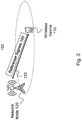
- FIGURE 3 is a block diagram illustrating an example of a network, according to a particular embodiment.
- Network 100 includes network node 120 (such as a base station or eNodeB) and wireless devices 110 (such as mobile phones, smart phones, laptop computers, tablet computers, or any other devices that can provide wireless communication).
- network node 120 such as a base station or eNodeB
- wireless devices 110 such as mobile phones, smart phones, laptop computers, tablet computers, or any other devices that can provide wireless communication.
- wireless devices 110 that are within coverage of network node 120 communicate with network node 120 by transmitting and receiving wireless signals 130.
- wireless devices 110 and network node 120 may communicate wireless signals 130 containing voice traffic, data traffic, and/or control signals.
- Wireless signals 130 may include both downlink transmissions (from network node 120 to wireless devices 110) and uplink transmissions (from wireless devices 110 to network node 120).
- Wireless signals 130 may include reference signals 150, such as DM-RS and CPE-RS.
- Wireless device 110 may use the reference signals to determine synchronization and error correction information for wireless signal 130 in the downlink.
- wireless device 110 may transmit reference signals, such as DM-RS and CPE-RS, in the uplink.
- Network node 120 may use the reference signals to determine synchronization and error correction information for wireless signal 130 in the uplink.
- Wireless signals 130 comprise radio frames which in turn comprise time/frequency resources, such as time/frequency resources 22 illustrated in FIGURE 2 described above.
- time/frequency resources 22 illustrated in FIGURE 2 described above Such time/frequency formats for reference signals 150 are illustrated in FIGURES 4-6 described below.
- Network node 120 transmits and receives wireless signals 130 using antenna 140.
- network node 120 may comprise multiple antennas 140.
- network node 120 may comprise a multi-input multi-output (MIMO) system with two, four, eight, or more antennas 140.
- MIMO multi-input multi-output
- each network node 120 may use any suitable radio access technology, such as long term evolution (LTE), LTE-Advanced, LTE-NX, 4G, 5G, UMTS, HSPA, GSM, cdma2000, WiMax, WiFi, and/or other suitable radio access technology.
- Network 100 may include any suitable combination of one or more radio access technologies. For purposes of example, various embodiments may be described within the context of certain radio access technologies. However, the scope of the disclosure is not limited to the examples and other embodiments could use different radio access technologies.
- embodiments of a network may include one or more wireless devices and one or more different types of network nodes capable of communicating with the wireless devices.
- the network may also include any additional elements suitable to support communication between wireless devices or between a wireless device and another communication device (such as a landline telephone).
- a wireless device may include any suitable combination of hardware and/or software.
- a wireless device such as wireless device 110
- a network node may include any suitable combination of hardware and/or software.
- a network node, such as network node 120 may include the components described with respect to FIGURE 10A below.
- Particular embodiments include a method in a wireless receiver, such as wireless device 110 (i.e., downlink) or network node 120 (i.e., uplink), for tracking common phase error using a code division multiplexed common phase error tracking reference signal.
- the receiver determines a CPE-RS OCC length and extracts all unique CPE-RS OCC code points in a first OFDM symbol. Further, the receiver performs first channel estimates on all DM-RS and extracts common phase error references for all of the unique CPE-RS code points. In a second OFDM symbol, the receiver extracts a second set of common phase errors references for all of the unique code points. The receiver performs separate common phase error compensation of the channel estimates using the set of unique CPE-RS OCC code points.
- Particular embodiments include a method in a wireless transmitter, such as network node 120 (i.e., downlink) or wireless device 110 (i.e., uplink), for generating code division multiplexed reference signals for common phase error tracking.
- the transmitter determines a CPE-OCC length and code points for CPE-RS generation to intended receivers. Further, the transmitter generates one or more DM-RS OCC of equal or longer length than the CPE-OCC length and determines signals for CPE-RS sub-carriers. The transmitter copies the determined signals to all CPE-RS sub-carriers for all OFDM symbols carrying CPE-RS. The transmitter then transmits data with the DM-RS and the CPE-RS.
- a wireless transmitter generates a CPE-RS from the effective transmitted DM-RS by using an orthogonal cover code (OCC) structure to facilitate code multiplexing of CPE-RS.
- OCC orthogonal cover code
- the symbols transmitted in the intersection of the CPE-RS and DMRS correspond to a first part of the OCC, referred to as CPE-OCC, and are copied to all other resource elements assigned to CPE-RS.
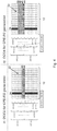
- An example is illustrated in FIGURE 4 .
- FIGURE 4 illustrates example time-frequency grids with copied demodulation DM-RS from node specific CPE-OCC for common phase error tracking, according to some embodiments.
- Grids 41 and 42 each comprise time/frequency resources 22.
- the horizontal axis represents time and the vertical axis represents frequency.
- Each grid includes DM-RS 24.
- Grid 41 represents CPE-RS generation using an OCC of length 2.
- Grid 41 includes two CPE-RS, CPE-RS 44 and 46, each generated from one of the OCC code points.
- Each of the time/frequency resources 22 assigned to CPE-RS 44 is a copy of the time/frequency resource 22 at the intersection of DM-RS 24 and CPE-RS 44.
- each of the time/frequency resources 22 assigned to CPE-RS 46 is a copy of the time/frequency resource 22 at the intersection of DM-RS 24 and CPE-RS 46.
- CPE-RS and DM-RS are illustrated using particular time/frequency resources 22, in other embodiments CPE-RS and DM-RS may use any suitable time/frequency resources 22.
- Grid 42 represents CPE-RS generation using an OCC of length 4.
- Grid 42 includes four CPE-RS, CPE-RS 44, 46, 48, and 50, each generated from one of the OCC code points.
- Each of the time/frequency resources 22 assigned to CPE-RS 44 is a copy of the time/frequency resource 22 at the intersection of DM-RS 24 and CPE-RS 44.
- each of the time/frequency resources 22 assigned to CPE-RS 46, 48, and 50 is a copy of the time/frequency resource 22 at the intersection of DM-RS 24 and CPE-RS 46, 48, and 50, respectively.
- CPE-RS and DM-RS are illustrated using particular time/frequency resources 22, in other embodiments CPE-RS and DM-RS may use any suitable time/frequency resources 22.
- the DM-RS signal is copied as the effective complex value transmitted in the resource element intersecting with the CPE-RS.
- the receiver determines that the CPE-RS signal is known from the intersecting DM-RS signal and copies it to corresponding subcarriers of the other OFDM symbols carrying CPE-RS.
- Particular embodiments may support common phase error tracking from two network nodes.
- a length-2 CPE-OCC may be used where, for example, one of the network nodes (BS0) uses the CPE-OCC code point [1,1] (assuming Walsh-Hadamard) and the other network node (BS1) uses the CPE-OCC code point [1,-1].
- BS0 may use all OCC4 code points generated from CPE-OCC [1,1] (i.e., DMRS-OCC [1,1,1,1] and [1,1,-1,-1]), and BS1 may use all OCC4 generated from CPE-OCC [1,-1] (i.e., DMRS-OCC [1,-1,1,-1] and [1,-1,-1,1]).
- code division multiplexing of CPE-RS may be used to compensate for phase error from multiple wireless devices.
- a length-4 CPE-OCC may support common phase noise tracking in MU-MIMO of four wireless devices (UE0, UE1, UE2, UE3) in uplink where UE0 uses CPE-OCC [1,1,1,1], UE1 use [1,-1,1,-1], etc.
- UE0 may use both available OCC8 code points for DMRS-OCC (i.e., [1,1,1,1,1,1] and [1,1,1,1,-1,-1,-1,-1] for DM-RS).
- Particular embodiments describe transmission from one or more transmitters affected by common phase errors to a single receiver.
- the same procedures may be used with each receiver.
- Some embodiments include signaling and configuration for CPR-RS.
- a wireless device may receive signaling to configure it how to extract CPE-RS and which CPE estimate is associated with a particular layer which in turn corresponds to a particular DM-RS.
- each transmitter may be configured with a CPE-OCC for CPE-RS generation and each receiver may be configured with a CPE-OCC length for CPE-RS extraction.
- Each CPE-OCC length may be associated with the same number of subcarriers for the mapping of the CPE-RS.
- a network node may control two transmitters that have independent common phase errors but are otherwise synchronized.
- the two transmitters may, for example, refer to two antenna panels in the same position but with separate VCOs and PAs, etc. Each of the panels may use two generated sub-sets of DM-RS and send CPE-RS using only their set of DM-RS, including relevant precoding.
- a first network node may generate CPE-RS using CPE-OCC [1,1] and use DM-RS derived from this CPE-OCC.
- the wireless device may be configured with OCC2 for CPE-RS and may extract the relation between DM-RS and CPE-RS.
- the wireless device is assigned DM-RS [1,1], [1,-1,1,-1], and [1,-1,-1,1], it can derive that both [1,1] and [1,-1] are used for CPE-RS extraction and that DM-RS [1,1] should use the [1,1] CPE-OCC and that the CPE-RS extracted from [1,-1] CPE-OCC should be used both for [1,-1,1,-1] and [1,-1,-1,1].
- the obtained CPE estimate from [1,1] CPE-OCC may be used to compensate the channel estimate derived from [1,1] DM-RS, and the CPE estimate derived from [1,-1] CPE-OCC may be used to compensate the channel estimates from the two later DM-RSs.
- the configuration and signaling can be dynamic (i.e., the CPE-RS OCC length is included in the DCI) or in a semi-static fashion (i.e., using higher layer signaling).
- the DM-RS may be generated using OCC within a comb structure.
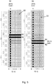
- the comb structure may separate multiple common phase errors via CPE-RS both in the frequency domain and in the code domain. For example, if two combs are used together with OCC2, then two CPE-RS may be generated from the combs. The additional CPE-RS are generated using the same procedure described above. An example is illustrated in FIGURE 5 .
- FIGURE 5 illustrates example time-frequency grids with DM-RS and CPE-RS using two combs in the frequency domain, according to particular embodiments.
- Subframes 10a and 10b each comprise 14 OFDM symbols comprising time/frequency resources 22.
- DM-RS is transmitted on two combs, combs 54 and 56.
- a length-2 CPE-OCC is used per comb for CPE tracking of common phase errors originating from potentially four independent transmissions (e.g., a MU-MIMO uplink scenario with four UEs).
- CPE-RS 58 and 60 and the DM-RS of comb 54 comprise particular time/frequency resources 22.
- CPE-RS 62 and 64 and the DM-RS of comb 56 comprise different time/frequency resources than those of comb 54.
- Time/frequency resources 22 marked with an X in comb 54 are the time/frequency resources 22 used for DM-RS and CPE-RS in comb 56, and vice versa.
- OCC lengths for CPE-RS generation on the two combs may use different OCC lengths for CPE-RS generation on the two combs (e.g., OCC2 on one comb and no code orthogonality on the other comb).
- One comb may use the code division multiplexed embodiments disclosed herein and the other comb may use an alternative or conventional solution without code multiplexing of CPE-RS.
- Some embodiments may use joint CPE processing over multiple CPE-OCC. Improved processing gain and better diversity on the CPE-RS may be achieved by using multiple code points for CPE-OCC. For example, by configuring a wireless device to associate both CPE-OCC [1,1] and [1,-1] with the same transmitter, the CPE estimate for both code-points can be processed jointly. This enables the network node to transmit CPE-RS in two "beams" with spatial diversity.
- OCC in time
- OCC in both time and frequency together.
- OCC is applied in the frequency domain.
- Other embodiments apply OCC in time domain.
- the CPE estimation is limited to the length of the OCC mapping in time. For example, if two OFDM symbols are used, then the CPE compensation is performed over 2 OFDM symbols. An example is illustrated in FIGURE 6 .
- FIGURE 6 illustrates example time-frequency grids with DM-RS and CPE-RS using time domain mapping of orthogonal cover codes, according to particular embodiments.
- Grids 70 and 71 each comprise time/frequency resources 22. The horizontal axis represents time and the vertical axis represents frequency.
- Grid 71 illustrates the same pattern of DM-RS and CPE-RS using timing domain mapping of orthogonal cover codes as grid 70. As illustrated in grids 70 and 71, the DM-RS is multiplexed in time using a length-2 OCC.
- Grids 71 and 72 include CPE-RS 72 and 74 multiplexed in frequency using a length-2 OCC.
- Each of the time/frequency resources 22 assigned to CPE-RS 72 is a copy of the pair of time/frequency resources 22 at the intersection of the DM-RS and CPE-RS 72.
- each of the time/frequency resources 22 assigned to CPE-RS 74 is a copy of the pair of time/frequency resources 22 at the intersection of the DM-RS and CPE-RS 74.
- the CPE estimation is performed over 2 OFDM symbols.
- CPE-RS and DM-RS are illustrated using particular time/frequency resources 22, in other embodiments CPE-RS and DM-RS may use any suitable time/frequency resources 22. Particular embodiments may use a combination of OCC in frequency and time applied to the CPE-RS.
- FIGURE 7 is a flowchart of an example method in a wireless receiver of compensating common phase error in a received wireless signal, according to some embodiments. In particular embodiments, one or more steps of the method may be performed by components of network 100 described with reference to FIGURE 3 .
- a wireless receiver obtains a value of a length N for an orthogonal cover code.
- wireless device 110 may receive signaling (e.g., DCI) from network node 120 informing wireless device 110 that network node 120 is transmitting CPE-RS generated from a length-2 OCC.
- the length N may be predetermined or wireless device 110 may be preconfigured with length N.
- the wireless receiver receives a first symbol of a wireless signal.
- the first symbol may comprise a code division multiplexed DM-RS multiplexed with a length M orthogonal cover code; and a first code division multiplexed CPE-RS multiplexed with a length N orthogonal cover code, wherein N is less than or equal to M.
- wireless device 110 may receive a first OFDM symbol, such as the third OFDM symbol illustrated in grid 41 of FIGURE 4 (i.e., the symbol 12 that contains DM-RS 24).
- DM-RS 24 is code division multiplexed in the frequency domain using, for example, a length-4 OCC.
- the same OFDM symbol includes CPE-RS 44 and 46 multiplexed in the frequency domain using a length-2 OCC.
- Other embodiments may use any suitable value of N and M for OCC.
- the wireless receiver determines M code points in the first symbol associated with a DM-RS. For example, wireless device 110 determines four code points associated with DM-RS 24 illustrated in grid 41 of FIGURE 4 .
- the wireless receiver estimates a channel corresponding to the received wireless signal using the M code points associated with the DM-RS. For example wireless device 110 estimates a channel associated with the wireless signal received from network node 120 based on the received DM-RS.
- the wireless device estimates a first CPE-RS corresponding to the estimated channel using the first N code points of the M code points associated with the DM-RS. For example, wireless device 110 determines two code points associated with CPE-RS 24 illustrated in grid 41 of FIGURE 4 (i.e., the intersection of DM-RS 24 and CPE-RS 44 and 46. Wireless device 110 uses these two code points to estimate the CPE-RS.
- the wireless device compensates the estimated channel for phase error using the estimated first CPE-RS.
- wireless device 110 uses the CPE-RS to modify the channel estimated using the DM-RS in step 718 to account for phase error.
- the wireless device receives a second symbol of the wireless signal.
- the second symbol comprises a second code division multiplexed CPE-RS multiplexed with the length N orthogonal cover code.
- wireless device 110 may receive a second OFDM symbol, such as the fourth OFDM symbol illustrated in grid 41 of FIGURE 4 (or any symbol 12 other than the third OFDM symbol that contains DM-RS 24).
- the wireless device determines the resource elements in the second symbol that corresponding to resource elements in the first symbol comprising the first N code points of the M code points associated with the DM-RS. For example, wireless device 110 determines the time/frequency resources 22 that include CPE-RS in the fourth OFDM symbol illustrated in grid 41 of FIGURE 4 .
- the wireless device estimates a second CPE-RS corresponding to the estimated channel using the determined resource elements in the second symbol. For example, wireless device 110 determines a second CPE-RS based on the resource elements determined in the previous step 726.
- the wireless device compensates the estimated channel for phase error using the estimated second CPE-RS.
- wireless device 110 compensates the channel estimated at previous step 718 for phase error using the second CPE-RS.
- FIGURE 8 is a flowchart of an example method in a wireless transmitter of transmitting a common phase error reference signal (CPE-RS), according to some embodiments. In particular embodiments, one or more steps of the method may be performed by components of network 100 described with reference to FIGURE 3 .
- CPE-RS common phase error reference signal
- a wireless transmitter determines a code division multiplexed CPE-RS multiplexed with a length N orthogonal cover code and comprising N code points.
- network node 120 may determine at least one of CPE-RS 44 and 46 illustrated in grid 41 of FIGURE 4 using a length-2 OCC.
- the wireless transmitter determines a code division multiplexed DM-RS multiplexed with a length M orthogonal cover code and comprising M code points, wherein M is greater than or equal to N and a first N code points of the DM-RS are generated from the CPE-RS.
- network node 120 may determine DM-RS 24 illustrated in grid 41 of FIGURE 4 using a length-4 OCC. Other embodiments may use any suitable value of N and M.
- the wireless transmitter transmits a first symbol of a radio frame comprising the code division multiplexed CPE-RS and the code division multiplexed DM-RS to a wireless receiver.
- network node may transmit the third OFDM symbol 12 illustrated in grid 41 of FIGURE 4 (i.e., the symbol 12 that contains DM-RS 24).
- the wireless transmitter copies the code division multiplexed CPE-RS to a second symbol of the radio frame.
- network node 120 copies the values of the two time/frequency resources 22 in the third OFDM symbol 12 illustrated in grid 41 of FIGURE 4 at the intersection of DM-RS 24 and CPE-RS 44 and 46 to the same time/frequency resources in any of the remaining OFDM symbols 12 in grid 41.
- the wireless transmitter transmits the second symbol of the radio frame to the wireless receiver.
- network node 120 transmits the fourth OFDM symbol 12 illustrated in grid 41 of FIGURE 4 to wireless device 110.
- FIGURE 9A is a block diagram illustrating an example embodiment of a wireless device.
- the wireless device is an example of the wireless device 110 illustrated in FIGURE 3 .
- the wireless device is capable of receiving a first symbol of a wireless signal comprising a code division multiplexed DM-RS a code division multiplexed CPE-RS.
- the wireless device is operable to determine code points in the first symbol associated with a DM-RS and estimate a channel corresponding to the received wireless signal using the code points.
- the wireless device is also operable to estimate a first CPE-RS corresponding to the estimated channel using the first N code points of code points associated with the DM-RS and compensating the estimated channel for phase error using the estimated first CPE-RS.
- the wireless device is capable of determining a code division multiplexed CPE-RS multiplexed with a length N orthogonal cover code and determining a code division multiplexed DM-RS multiplexed with a length M orthogonal cover code a first N code points of the DM-RS are generated from the CPE-RS.
- the wireless device is operable to transmit a first symbol of a radio frame comprising the code division multiplexed CPE-RS and the code division multiplexed DM-RS to a wireless receiver.
- a wireless device include a mobile phone, a smart phone, a PDA (Personal Digital Assistant), a portable computer (e.g., laptop, tablet), a sensor, a modem, a machine type (MTC) device / machine to machine (M2M) device, laptop embedded equipment (LEE), laptop mounted equipment (LME), USB dongles, a device-to-device capable device, a vehicle-to-vehicle device, or any other device that can provide wireless communication.
- the wireless device includes transceiver 910, processor 920, and memory 930.
- transceiver 910 facilitates transmitting wireless signals to and receiving wireless signals from wireless network node 120 (e.g., via an antenna), processor 920 executes instructions to provide some or all of the functionality described herein as provided by the wireless device, and memory 930 stores the instructions executed by processor 920.
- Processor 920 includes any suitable combination of hardware and software implemented in one or more integrated circuits or modules to execute instructions and manipulate data to perform some or all of the described functions of the wireless device.
- processor 920 may include, for example, one or more computers, one more programmable logic devices, one or more central processing units (CPUs), one or more microprocessors, one or more applications, and/or other logic, and/or any suitable combination of the preceding.
- Processor 920 may include analog and/or digital circuitry configured to perform some or all of the described functions of wireless device 110.
- processor 920 may include resistors, capacitors, inductors, transistors, diodes, and/or any other suitable circuit components.
- Memory 930 is generally operable to store computer executable code and data.
- Examples of memory 730 include computer memory (e.g., Random Access Memory (RAM) or Read Only Memory (ROM)), mass storage media (e.g., a hard disk), removable storage media (e.g., a Compact Disk (CD) or a Digital Video Disk (DVD)), and/or or any other volatile or non-volatile, non-transitory computer-readable and/or computer-executable memory devices that store information.
- RAM Random Access Memory
- ROM Read Only Memory
- mass storage media e.g., a hard disk
- removable storage media e.g., a Compact Disk (CD) or a Digital Video Disk (DVD)
- CD Compact Disk
- DVD Digital Video Disk
- processor 920 in communication with transceiver 910 transmits and receives code division multiplexed reference signals, such as DM-RS and CPE-RS.
- wireless device may include additional components (beyond those shown in FIGURE 9A ) responsible for providing certain aspects of the wireless device's functionality, including any of the functionality described above and/or any additional functionality (including any functionality necessary to support the solution described above).
- FIGURE 9B is a block diagram illustrating example components of a wireless device 110.
- the components may include receiving module 950, determining module 952, estimating module 954, error compensating module 956, and transmitting module 958.
- Receiving module 950 may perform the receiving functions of wireless device 110. For example, receiving module 950 may receive a length-N from network node 120. Receiving module 950 may receive a wireless signal from network node 120 that includes code division multiplexed reference signals, such as DM-RS and CPE-RS. In certain embodiments, receiving module 950 may include or be included in processor 920. Receiving module 950 may include circuitry configured to receive radio signals. In particular embodiments, receiving module 950 may communicate with determining module 952, estimating module 954, error compensating module 956, and transmitting module 958.
- Determining module 952 may perform the determining functions of wireless device 110. For example, determining module 952 may determine a code division multiplexed CPE-RS multiplexed with a length N orthogonal cover code and comprising N code points, and determine a code division multiplexed DM-RS multiplexed with a length M orthogonal cover code and comprising M code points, wherein M is greater than or equal to N and a first N code points of the DM-RS are generated from the CPE-RS. In some embodiments, determining module 952 may determine M code points associated with a DM-RS. In certain embodiments, determining module 952 may include or be included in processor 920. In particular embodiments, determining module 952 may communicate with receiving module 950, estimating module 954, error compensating module 956, and transmitting module 958.
- Estimating module 954 may perform the estimating functions of wireless device 110. For example, estimating module 954 may estimate a wireless channel using a DM-RS and may estimate a CPE-RS using code points associated with the DM-RS. In certain embodiments, estimating module 954 may include or be included in processor 920. In particular embodiments, estimating module 954 may communicate with receiving module 950, determining module 952, error compensating module 956, and transmitting module 958.
- Error compensating module 956 may perform the error compensating functions of wireless device 110. For example, error compensating module 956 may compensate an estimated channel for phase error based on a CPE-RS. In certain embodiments, error compensating module 956 may include or be included in processor 920. In particular embodiments, error compensating module 956 may communicate with receiving module 950, determining module 952, estimating module 954, and transmitting module 958.
- Transmitting module 958 may perform the transmitting functions of wireless device 110. For example, transmitting module 958 may transmit a radio frame comprising a code division multiplexed CPE-RS and a code division multiplexed DM-RS. In certain embodiments, transmitting module 958 may include or be included in processor 920. Transmitting module 958 may include circuitry configured to transmit radio signals. In particular embodiments, transmitting module 958 may communicate with obtaining module 950, requesting module 952, receiving module 954, and error compensating module 956.
- FIGURE 10A is a block diagram illustrating an example embodiment of a network node.
- the network node is an example of the network node 120 illustrated in FIGURE 3 .
- the network node is capable of receiving a first symbol of a wireless signal comprising a code division multiplexed DM-RS a code division multiplexed CPE-RS.
- the network node is operable to determine code points in the first symbol associated with a DM-RS and estimate a channel corresponding to the received wireless signal using the code points.
- the network node is also operable to estimate a first CPE-RS corresponding to the estimated channel using the first N code points of code points associated with the DM-RS and compensating the estimated channel for phase error using the estimated first CPE-RS.
- the network node is capable of determining a code division multiplexed CPE-RS multiplexed with a length N orthogonal cover code and determining a code division multiplexed DM-RS multiplexed with a length M orthogonal cover code a first N code points of the DM-RS are generated from the CPE-RS.
- the network node is operable to transmit a first symbol of a radio frame comprising the code division multiplexed CPE-RS and the code division multiplexed DM-RS to a wireless receiver.
- Network node 120 can be an eNodeB, a nodeB, a base station, a wireless access point (e.g., a Wi-Fi access point), a low power node, a base transceiver station (BTS), a transmission point or node, a remote RF unit (RRU), a remote radio head (RRH), or other radio access node.
- Network node 120 includes at least one transceiver 1010, at least one processor 1020, at least one memory 1030, and at least one network interface 1040.
- Transceiver 1010 facilitates transmitting wireless signals to and receiving wireless signals from a wireless device, such as wireless devices 110 (e.g., via an antenna); processor 1020 executes instructions to provide some or all of the functionality described above as being provided by a network node 120; memory 1030 stores the instructions executed by processor 1020; and network interface 1040 communicates signals to backend network components, such as a gateway, switch, router, Internet, Public Switched Telephone Network (PSTN), controller, and/or other network nodes 120.
- Processor 1020 and memory 1030 can be of the same types as described with respect to processor 920 and memory 930 of FIGURE 9A above.
- network interface 1040 is communicatively coupled to processor 1020 and refers to any suitable device operable to receive input for network node 120, send output from network node 120, perform suitable processing of the input or output or both, communicate to other devices, or any combination of the preceding.
- Network interface 1040 includes appropriate hardware (e.g., port, modem, network interface card, etc.) and software, including protocol conversion and data processing capabilities, to communicate through a network.
- processor 1020 in communication with transceiver 1010 transmits and receives code division multiplexed reference signals, such as DM-RS and CPE-RS.
- network node 120 includes additional components (beyond those shown in FIGURE 10 ) responsible for providing certain aspects of the network node's functionality, including any of the functionality described above and/or any additional functionality (including any functionality necessary to support the solution described above).
- the various different types of radio network nodes may include components having the same physical hardware but configured (e.g., via programming) to support different radio access technologies, or may represent partly or entirely different physical components.
- FIGURE 10B is a block diagram illustrating example components of a network node 120.
- the components may include receiving module 1050, determining module 1052, estimating module 1054, error compensating module 1056, and transmitting module 1058.
- Receiving module 1050 may perform the receiving functions of network node 120. For example, receiving module 1050 may receive a length-N from wireless device 110. Receiving module 1050 may receive a wireless signal from wireless device 110 that includes code division multiplexed reference signals, such as DM-RS and CPE-RS. In certain embodiments, receiving module 1050 may include or be included in processor 1020. Receiving module 1050 may include circuitry configured to receive radio signals. In particular embodiments, receiving module 1050 may communicate with determining module 1052, estimating module 1054, error compensating module 1056, and transmitting module 1058.
- Determining module 1052 may perform the determining functions of network node 120. For example, determining module 1052 may determine a code division multiplexed CPE-RS multiplexed with a length N orthogonal cover code and comprising N code points, and determine a code division multiplexed DM-RS multiplexed with a length M orthogonal cover code and comprising M code points, wherein M is greater than or equal to N and a first N code points of the DM-RS are generated from the CPE-RS. In some embodiments, determining module 1052 may determine M code points associated with a DM-RS. In certain embodiments, determining module 1052 may include or be included in processor 1020. In particular embodiments, determining module 1052 may communicate with receiving module 1050, estimating module 1054, error compensating module 1056, and transmitting module 1058.
- Estimating module 1054 may perform the estimating functions of network node 120. For example, estimating module 1054 may estimate a wireless channel using a DM-RS and may estimate a CPE-RS using code points associated with the DM-RS. In certain embodiments, estimating module 1054 may include or be included in processor 1020. In particular embodiments, estimating module 1054 may communicate with receiving module 1050, determining module 1052, error compensating module 1056, and transmitting module 1058.
- Error compensating module 1056 may perform the error compensating functions of network node 120. For example, error compensating module 1056 may compensate an estimated channel for phase error based on a CPE-RS. In certain embodiments, error compensating module 1056 may include or be included in processor 1020. In particular embodiments, error compensating module 1056 may communicate with receiving module 1050, determining module 1052, estimating module 1054, and transmitting module 1058.
- Transmitting module 1058 may perform the transmitting functions of network node 120. For example, transmitting module 1058 may transmit a radio frame comprising a code division multiplexed CPE-RS and a code division multiplexed DM-RS. In certain embodiments, transmitting module 1058 may include or be included in processor 1020. Transmitting module 1058 may include circuitry configured to transmit radio signals. In particular embodiments, transmitting module 1058 may communicate with obtaining module 1050, requesting module 1052, receiving module 1054, and error compensating module 1056.
- the methods and apparatus disclosed herein may improve CPE-RS resource utilization compared to conventional solutions. Full utilization of all sub-carriers is possible for DMRS while utilizing code-domain for the CPE-RS extraction. This improves processing gain for CPE tracking without the need for power boosting solutions (which are needed in conventional solutions to improve coverage). Thus, in particular embodiments the allocation of CPE-RS may not limit the maximum number of available DM-RS layers.
- Another advantage is improved support for extended common phase noise tracking in MU-MIMO operations and in CoMP deployments with multiple transmission points. Furthermore, particular embodiments use marginal additional signaling for configuring CPE-RS. Particular embodiments facilitate a flexible configuration of a longer length DMRS-OCC and a shorter length CPE-OCC at the same time. Some embodiments may benefit from some, none, or all of these advantages. Other technical advantages may be readily ascertained by one of ordinary skill in the art.
Landscapes
- Engineering & Computer Science (AREA)
- Signal Processing (AREA)
- Computer Networks & Wireless Communication (AREA)
- Power Engineering (AREA)
- Mobile Radio Communication Systems (AREA)
Claims (12)
- Verfahren in einem drahtlosen Empfänger (110, 120) zum Korrigieren eines gemeinsamen Phasenfehlers in einem empfangenen drahtlosen Signal (130), wobei das Verfahren Folgendes umfasst:Empfangen, von einem drahtlosen Sender (110, 120), eines Werts N einer Länge eines orthogonalen Cover-Codes in Downlink-Steuerinformationen (DCI);Empfangen (714), von dem drahtlosen Sender (110, 120), eines ersten Symbols (12) des drahtlosen Signals (130), wobei das erste Symbol (12) Folgendes umfasst:
ein Demodulations-Referenzsignal (DM-RS), das einem Codemultiplexverfahren mit einem Referenzsignal (CPE-RS) des gemeinsamen Phasenfehlers- unterzogen wurde, dadurch gekennzeichnet, dass das DM-RS für das Codemultiplexen einen orthogonalen Cover-Code mit einer Länge M verwendet und das CPE-RS für das Codemultiplexen den orthogonalen Cover-Code mit der Länge N verwendet, wobei N kleiner oder gleich M ist und N dem empfangenen DCI-Wert entspricht;Bestimmen (716) von M Code-Punkten in dem ersten Symbol (12), die mit dem orthogonalen Cover-Code mit der Länge M des DM-RS assoziiert sind;Schätzen (718) eines Kanals, der dem empfangenen drahtlosen Signal (130) entspricht, unter Verwendung der M Code-Punkte, die mit dem DM-RS assoziiert sind;Schätzen (720) des CPE-RS, das dem geschätzten Kanal entspricht, unter Verwendung von N Code-Punkten der M Code-Punkte, die mit dem DM-RS assoziiert sind; undKorrigieren (722) des geschätzten Kanals hinsichtlich des Phasenfehlers unter Verwendung des geschätzten CPE-RS. - Verfahren nach Anspruch 1, wobei das erste Symbol (12) ferner ein Symbol umfasst, das einem orthogonalen Frequenzmultiplexverfahren (OFDM) unterzogen wurde.
- Verfahren nach einem der Ansprüche 1-2, wobei der orthogonale Cover-Code eines von einem Walsh-Hadamard-Code oder einem Code einer diskreten Fourier Transformationen (DFT) umfasst.
- Verfahren in einem drahtlosen Sender (110, 120) zum Senden eines Referenzsignals eines gemeinsamen Phasenfehlers, wobei das Verfahren Folgendes umfasst:Senden eines Werts N einer Länge eines orthogonalen Cover-Codes in Downlink-Steuerinformationen (DCI) an einen drahtlosen Empfänger (110, 120);Bestimmen (814) eines Demodulations-Referenzsignals (DM-RS), das einem Codemultiplexverfahren mit einem Referenzsignal (CPE-RS) des gemeinsamen Phasenfehlers unterzogen wurde, dadurch gekennzeichnet, dass das DM-RS für das Codemultiplexen einen orthogonalen Cover-Code mit einer Länge M verwendet und das CPE-RS für das Codemultiplexen den orthogonalen Cover-Code mit der Länge N verwendet, wobei M größer oder gleich N ist und N dem gesendeten DCI-Wert entspricht; undSenden (816) eines ersten Symbols (12) eines Funkrahmens an den drahtlosen Empfänger (110, 120), welches das bestimmte DM-RS umfasst, das einem Codemultiplexverfahren mit dem CPE-RS unterzogen wurde.
- Verfahren nach Anspruch 4, wobei das erste Symbol (12) ferner ein Symbol umfasst, das einem orthogonalen Frequenzmultiplexverfahren (OFDM) unterzogen wurde.
- Verfahren nach einem der Ansprüche 4-5, wobei der orthogonale Cover-Code eines von einem Walsh-Hadamard-Code oder einem Code einer diskreten Fourier Transformationen (DFT) umfasst.
- Drahtloser Empfänger (110, 120), der dazu betrieben werden kann, einen gemeinsamen Phasenfehler in einem empfangenen drahtlosen Signal (130) zu korrigieren, wobei der drahtlose Empfänger (110, 120) einen Prozessor (920, 1020) und einen Speicher (930, 1030) umfasst und der Prozessor (920, 1020) für Folgendes betrieben werden kann:Empfangen, von einem drahtlosen Sender (110, 120), eines Werts N einer Länge eines orthogonalen Cover-Codes in Downlink-Steuerinformationen (DCI);Empfangen, von dem drahtlosen Sender (110, 120), eines ersten Symbols (12) des drahtlosen Signals (130), wobei das erste Symbol (12) Folgendes umfasst:
ein Demodulations-Referenzsignal (DM-RS), das einem Codemultiplexverfahren mit einem Referenzsignal (CPE-RS) des gemeinsamen Phasenfehlers unterzogen wurde, dadurch gekennzeichnet, dass das DM-RS für das Codemultiplexen einen orthogonalen Cover-Code mit einer Länge M verwendet und das CPE-RS für das Codemultiplexen den orthogonalen Cover-Code mit der Länge N verwendet, wobei N kleiner oder gleich M ist und N dem empfangenen DCI-Wert entspricht;Bestimmen von M Code-Punkten in dem ersten Symbol (12), die mit dem orthogonalen Cover-Code mit der Länge M des DM-RS assoziiert sind;Schätzen eines Kanals, der dem empfangenen drahtlosen Signal (130) entspricht, unter Verwendung der M Code-Punkte, die mit dem DM-RS assoziiert sind;Schätzen des CPE-RS, das dem geschätzten Kanal entspricht, unter Verwendung von N Code-Punkten der M Code-Punkte, die mit dem DM-RS assoziiert sind; undKorrigieren des geschätzten Kanals hinsichtlich des Phasenfehlers unter Verwendung des geschätzten CPE-RS. - Drahtloser Empfänger (110, 120) nach Anspruch 7, wobei das erste Symbol (12) ferner ein Symbol umfasst, das einem orthogonalen Frequenzmultiplexverfahren (OFDM) unterzogen wurde.
- Drahtloser Empfänger nach einem der Ansprüche 7-8, wobei der orthogonale Cover-Code eines von einem Walsh-Hadamard-Code oder einem Code einer diskreten Fourier Transformationen (DFT) umfasst.
- Drahtloser Sender (110, 120), der dazu betrieben werden kann, ein Referenzsignal eines gemeinsamen Phasenfehlers zu senden, wobei der drahtlose Sender (110, 120) einen Prozessor (920, 1020) und einen Speicher (930, 1030) umfasst und der Prozessor (920, 1020) für Folgendes betrieben werden kann:Senden eines Werts N einer Länge eines orthogonalen Cover-Codes in Downlink-Steuerinformationen (DCI) an einen drahtlosen Empfänger (110, 120);Bestimmen eines Demodulations-Referenzsignals (DM-RS), das einem Codemultiplexverfahren mit einem Referenzsignal (CPE-RS) des gemeinsamen Phasenfehlers unterzogen wurde, dadurch gekennzeichnet, dass das DM-RS für das Codemultiplexen einen orthogonalen Cover-Code mit einer Länge M verwendet und das CPE-RS für das Codemultiplexen den orthogonalen Cover-Code mit der Länge N verwendet, wobei M größer oder gleich N ist und N dem gesendeten DCI-Wert entspricht; undSenden eines ersten Symbols (12) eines Funkrahmens an den drahtlosen Empfänger (110, 120), welches das bestimmte DM-RS umfasst, das einem Codemultiplexverfahren mit dem CPE-RS unterzogen wurde.
- Drahtloser Empfänger (110, 120) nach Anspruch 10, wobei das erste Symbol (12) ferner ein Symbol umfasst, das einem orthogonalen Frequenzmultiplexverfahren (OFDM) unterzogen wurde.
- Drahtloser Empfänger (110, 120) nach einem der Ansprüche 10-11, wobei der orthogonale Cover-Code eines von einem Walsh-Hadamard-Code oder einem Code einer diskreten Fourier Transformationen (DFT) umfasst.
Applications Claiming Priority (2)
| Application Number | Priority Date | Filing Date | Title |
|---|---|---|---|
| US201662321369P | 2016-04-12 | 2016-04-12 | |
| PCT/SE2016/050802 WO2017180036A1 (en) | 2016-04-12 | 2016-08-25 | Common phase error compensation |
Publications (2)
| Publication Number | Publication Date |
|---|---|
| EP3443699A1 EP3443699A1 (de) | 2019-02-20 |
| EP3443699B1 true EP3443699B1 (de) | 2021-07-14 |
Family
ID=56926250
Family Applications (1)
| Application Number | Title | Priority Date | Filing Date |
|---|---|---|---|
| EP16766100.8A Active EP3443699B1 (de) | 2016-04-12 | 2016-08-25 | Gemeinsamen phasenfehler-korrektur |
Country Status (4)
| Country | Link |
|---|---|
| US (1) | US10985792B2 (de) |
| EP (1) | EP3443699B1 (de) |
| CN (1) | CN109075925B (de) |
| WO (1) | WO2017180036A1 (de) |
Families Citing this family (8)
| Publication number | Priority date | Publication date | Assignee | Title |
|---|---|---|---|---|
| JP6556950B2 (ja) * | 2015-10-30 | 2019-08-07 | 華為技術有限公司Huawei Technologies Co.,Ltd. | 信号送信装置、信号受信装置、シンボルタイミング同期方法、及びシステム |
| US10411914B2 (en) * | 2016-12-14 | 2019-09-10 | Intel IP Corporation | Data detection in MIMO systems with demodulation and tracking reference signals |
| CN108632005B (zh) | 2017-03-24 | 2023-12-15 | 华为技术有限公司 | 一种参考信号传输方法、装置及系统 |
| JP6888116B2 (ja) | 2017-03-31 | 2021-06-16 | エルジー エレクトロニクス インコーポレイティド | 無線通信システムにおいて参照信号を送受信するための方法及びそのための装置 |
| US10841143B2 (en) * | 2017-12-12 | 2020-11-17 | Qualcomm Incorporated | Phase tracking reference signal for sub-symbol phase tracking |
| EP4055944B1 (de) * | 2019-11-08 | 2025-02-26 | Telefonaktiebolaget LM Ericsson (publ) | Aktualisierung des aktiven tci-status für einzel-pdcch-basierten multi-trp-pdsch oder multi-pdcch-basierten multi-trp-pdsch |
| WO2022231484A1 (en) * | 2021-04-28 | 2022-11-03 | Telefonaktiebolaget Lm Ericsson (Publ) | Multi-layer pt-rs |
| CN118555674B (zh) * | 2022-04-28 | 2026-03-10 | 中兴通讯股份有限公司 | 解调参考信号和相位跟踪参考信号关联的指示 |
Family Cites Families (13)
| Publication number | Priority date | Publication date | Assignee | Title |
|---|---|---|---|---|
| US7826514B2 (en) * | 2003-04-24 | 2010-11-02 | Nec Corporation | Radio transmitter-receiving apparatus and radio transmitting-receiving method for estimating noise and interference power in radio transmission using code spread |
| US7481109B2 (en) * | 2005-03-04 | 2009-01-27 | Custom Sensors & Technologies, Inc. | Inertial measurement system and method with bias cancellation |
| US20110142107A1 (en) * | 2009-06-16 | 2011-06-16 | Kyle Jung-Lin Pan | Rank Adaptive Cyclic Shift for Demodulation Reference Signal |
| US8750257B2 (en) * | 2009-10-12 | 2014-06-10 | Lg Electronics Inc. | Method and apparatus for providing downlink reference signal transmission power information in a wireless communication system that supports multiple antennas |
| WO2011085509A1 (en) * | 2010-01-12 | 2011-07-21 | Telefonaktiebolaget L M Ericsson (Publ) | Layer-to dm rs port mapping for lte-advanced |
| BR112012016405B1 (pt) | 2010-01-20 | 2021-06-08 | Telefonaktiebolaget Lm Ericsson (Publ) | método implementado por uma estação base para transmitir sinais de referência de demodulação para um terminal de usuário, método implementado por um terminal de usuário para receber sinais de referência de demodulação transmitidos por uma estação base, estação base, e terminal de usuário |
| CN102237961A (zh) * | 2010-05-04 | 2011-11-09 | 株式会社Ntt都科摩 | 一种多输入多输出相关信息传输方法 |
| US9420511B2 (en) | 2012-11-01 | 2016-08-16 | Intel Corporation | Signaling QoS requirements and UE power preference in LTE-A networks |
| WO2014107136A1 (en) * | 2013-01-04 | 2014-07-10 | Telefonaktiebolaget L M Ericsson (Publ) | Method for estimating frequency offset using quasi-co-located reference signals |
| KR20140110676A (ko) * | 2013-03-08 | 2014-09-17 | 인텔렉추얼디스커버리 주식회사 | NCT(New Carrier Type)인 캐리어에서 복조참조신호를 전송 및 수신하는 방법과 장치 |
| EP3105875B1 (de) * | 2014-02-10 | 2020-05-13 | Telefonaktiebolaget LM Ericsson (publ) | Kopplung von referenzsignalen in einem drahtlosen netzwerk |
| WO2016171765A1 (en) * | 2015-04-22 | 2016-10-27 | Intel IP Corporation | Transmission designs for radio access technologies |
| US10439663B2 (en) * | 2016-04-06 | 2019-10-08 | Qualcomm Incorporated | Methods and apparatus for phase noise estimation in data symbols for millimeter wave communications |
-
2016
- 2016-08-25 EP EP16766100.8A patent/EP3443699B1/de active Active
- 2016-08-25 WO PCT/SE2016/050802 patent/WO2017180036A1/en not_active Ceased
- 2016-08-25 US US16/090,879 patent/US10985792B2/en active Active
- 2016-08-25 CN CN201680084528.9A patent/CN109075925B/zh not_active Expired - Fee Related
Non-Patent Citations (1)
| Title |
|---|
| None * |
Also Published As
| Publication number | Publication date |
|---|---|
| EP3443699A1 (de) | 2019-02-20 |
| CN109075925B (zh) | 2021-06-01 |
| US10985792B2 (en) | 2021-04-20 |
| CN109075925A (zh) | 2018-12-21 |
| US20200328768A1 (en) | 2020-10-15 |
| WO2017180036A1 (en) | 2017-10-19 |
Similar Documents
| Publication | Publication Date | Title |
|---|---|---|
| US12301398B2 (en) | Systems and methods for phase noise tracking reference signal sequence generation using demodulation reference signals | |
| US11637721B2 (en) | Methods and arrangements for channel estimation | |
| EP3443699B1 (de) | Gemeinsamen phasenfehler-korrektur | |
| CN110754056B (zh) | 在无线通信系统中发送和接收参考信号的方法及其设备 | |
| KR20210042359A (ko) | 사용자 장비에 의해 실행되는 방법 및 사용자 장비 |
Legal Events
| Date | Code | Title | Description |
|---|---|---|---|
| STAA | Information on the status of an ep patent application or granted ep patent |
Free format text: STATUS: UNKNOWN |
|
| STAA | Information on the status of an ep patent application or granted ep patent |
Free format text: STATUS: THE INTERNATIONAL PUBLICATION HAS BEEN MADE |
|
| PUAI | Public reference made under article 153(3) epc to a published international application that has entered the european phase |
Free format text: ORIGINAL CODE: 0009012 |
|
| STAA | Information on the status of an ep patent application or granted ep patent |
Free format text: STATUS: REQUEST FOR EXAMINATION WAS MADE |
|
| 17P | Request for examination filed |
Effective date: 20180831 |
|
| AK | Designated contracting states |
Kind code of ref document: A1 Designated state(s): AL AT BE BG CH CY CZ DE DK EE ES FI FR GB GR HR HU IE IS IT LI LT LU LV MC MK MT NL NO PL PT RO RS SE SI SK SM TR |
|
| AX | Request for extension of the european patent |
Extension state: BA ME |
|
| DAV | Request for validation of the european patent (deleted) | ||
| DAX | Request for extension of the european patent (deleted) | ||
| STAA | Information on the status of an ep patent application or granted ep patent |
Free format text: STATUS: EXAMINATION IS IN PROGRESS |
|
| 17Q | First examination report despatched |
Effective date: 20190920 |
|
| GRAP | Despatch of communication of intention to grant a patent |
Free format text: ORIGINAL CODE: EPIDOSNIGR1 |
|
| STAA | Information on the status of an ep patent application or granted ep patent |
Free format text: STATUS: GRANT OF PATENT IS INTENDED |
|
| INTG | Intention to grant announced |
Effective date: 20210329 |
|
| GRAS | Grant fee paid |
Free format text: ORIGINAL CODE: EPIDOSNIGR3 |
|
| GRAA | (expected) grant |
Free format text: ORIGINAL CODE: 0009210 |
|
| STAA | Information on the status of an ep patent application or granted ep patent |
Free format text: STATUS: THE PATENT HAS BEEN GRANTED |
|
| AK | Designated contracting states |
Kind code of ref document: B1 Designated state(s): AL AT BE BG CH CY CZ DE DK EE ES FI FR GB GR HR HU IE IS IT LI LT LU LV MC MK MT NL NO PL PT RO RS SE SI SK SM TR |
|
| REG | Reference to a national code |
Ref country code: GB Ref legal event code: FG4D |
|
| REG | Reference to a national code |
Ref country code: IE Ref legal event code: FG4D |
|
| REG | Reference to a national code |
Ref country code: DE Ref legal event code: R096 Ref document number: 602016060619 Country of ref document: DE |
|
| REG | Reference to a national code |
Ref country code: AT Ref legal event code: REF Ref document number: 1411493 Country of ref document: AT Kind code of ref document: T Effective date: 20210815 |
|
| REG | Reference to a national code |
Ref country code: NL Ref legal event code: FP |
|
| REG | Reference to a national code |
Ref country code: LT Ref legal event code: MG9D |
|
| REG | Reference to a national code |
Ref country code: AT Ref legal event code: MK05 Ref document number: 1411493 Country of ref document: AT Kind code of ref document: T Effective date: 20210714 |
|
| PG25 | Lapsed in a contracting state [announced via postgrant information from national office to epo] |
Ref country code: SE Free format text: LAPSE BECAUSE OF FAILURE TO SUBMIT A TRANSLATION OF THE DESCRIPTION OR TO PAY THE FEE WITHIN THE PRESCRIBED TIME-LIMIT Effective date: 20210714 Ref country code: RS Free format text: LAPSE BECAUSE OF FAILURE TO SUBMIT A TRANSLATION OF THE DESCRIPTION OR TO PAY THE FEE WITHIN THE PRESCRIBED TIME-LIMIT Effective date: 20210714 Ref country code: ES Free format text: LAPSE BECAUSE OF FAILURE TO SUBMIT A TRANSLATION OF THE DESCRIPTION OR TO PAY THE FEE WITHIN THE PRESCRIBED TIME-LIMIT Effective date: 20210714 Ref country code: FI Free format text: LAPSE BECAUSE OF FAILURE TO SUBMIT A TRANSLATION OF THE DESCRIPTION OR TO PAY THE FEE WITHIN THE PRESCRIBED TIME-LIMIT Effective date: 20210714 Ref country code: HR Free format text: LAPSE BECAUSE OF FAILURE TO SUBMIT A TRANSLATION OF THE DESCRIPTION OR TO PAY THE FEE WITHIN THE PRESCRIBED TIME-LIMIT Effective date: 20210714 Ref country code: NO Free format text: LAPSE BECAUSE OF FAILURE TO SUBMIT A TRANSLATION OF THE DESCRIPTION OR TO PAY THE FEE WITHIN THE PRESCRIBED TIME-LIMIT Effective date: 20211014 Ref country code: PT Free format text: LAPSE BECAUSE OF FAILURE TO SUBMIT A TRANSLATION OF THE DESCRIPTION OR TO PAY THE FEE WITHIN THE PRESCRIBED TIME-LIMIT Effective date: 20211115 Ref country code: LT Free format text: LAPSE BECAUSE OF FAILURE TO SUBMIT A TRANSLATION OF THE DESCRIPTION OR TO PAY THE FEE WITHIN THE PRESCRIBED TIME-LIMIT Effective date: 20210714 Ref country code: BG Free format text: LAPSE BECAUSE OF FAILURE TO SUBMIT A TRANSLATION OF THE DESCRIPTION OR TO PAY THE FEE WITHIN THE PRESCRIBED TIME-LIMIT Effective date: 20211014 Ref country code: AT Free format text: LAPSE BECAUSE OF FAILURE TO SUBMIT A TRANSLATION OF THE DESCRIPTION OR TO PAY THE FEE WITHIN THE PRESCRIBED TIME-LIMIT Effective date: 20210714 |
|
| PG25 | Lapsed in a contracting state [announced via postgrant information from national office to epo] |
Ref country code: PL Free format text: LAPSE BECAUSE OF FAILURE TO SUBMIT A TRANSLATION OF THE DESCRIPTION OR TO PAY THE FEE WITHIN THE PRESCRIBED TIME-LIMIT Effective date: 20210714 Ref country code: LV Free format text: LAPSE BECAUSE OF FAILURE TO SUBMIT A TRANSLATION OF THE DESCRIPTION OR TO PAY THE FEE WITHIN THE PRESCRIBED TIME-LIMIT Effective date: 20210714 Ref country code: GR Free format text: LAPSE BECAUSE OF FAILURE TO SUBMIT A TRANSLATION OF THE DESCRIPTION OR TO PAY THE FEE WITHIN THE PRESCRIBED TIME-LIMIT Effective date: 20211015 |
|
| REG | Reference to a national code |
Ref country code: CH Ref legal event code: PL |
|
| REG | Reference to a national code |
Ref country code: DE Ref legal event code: R097 Ref document number: 602016060619 Country of ref document: DE |
|
| REG | Reference to a national code |
Ref country code: BE Ref legal event code: MM Effective date: 20210831 |
|
| PG25 | Lapsed in a contracting state [announced via postgrant information from national office to epo] |
Ref country code: LI Free format text: LAPSE BECAUSE OF NON-PAYMENT OF DUE FEES Effective date: 20210831 Ref country code: DK Free format text: LAPSE BECAUSE OF FAILURE TO SUBMIT A TRANSLATION OF THE DESCRIPTION OR TO PAY THE FEE WITHIN THE PRESCRIBED TIME-LIMIT Effective date: 20210714 Ref country code: CH Free format text: LAPSE BECAUSE OF NON-PAYMENT OF DUE FEES Effective date: 20210831 |
|
| PLBE | No opposition filed within time limit |
Free format text: ORIGINAL CODE: 0009261 |
|
| STAA | Information on the status of an ep patent application or granted ep patent |
Free format text: STATUS: NO OPPOSITION FILED WITHIN TIME LIMIT |
|
| PG25 | Lapsed in a contracting state [announced via postgrant information from national office to epo] |
Ref country code: SM Free format text: LAPSE BECAUSE OF FAILURE TO SUBMIT A TRANSLATION OF THE DESCRIPTION OR TO PAY THE FEE WITHIN THE PRESCRIBED TIME-LIMIT Effective date: 20210714 Ref country code: SK Free format text: LAPSE BECAUSE OF FAILURE TO SUBMIT A TRANSLATION OF THE DESCRIPTION OR TO PAY THE FEE WITHIN THE PRESCRIBED TIME-LIMIT Effective date: 20210714 Ref country code: RO Free format text: LAPSE BECAUSE OF FAILURE TO SUBMIT A TRANSLATION OF THE DESCRIPTION OR TO PAY THE FEE WITHIN THE PRESCRIBED TIME-LIMIT Effective date: 20210714 Ref country code: MC Free format text: LAPSE BECAUSE OF FAILURE TO SUBMIT A TRANSLATION OF THE DESCRIPTION OR TO PAY THE FEE WITHIN THE PRESCRIBED TIME-LIMIT Effective date: 20210714 Ref country code: LU Free format text: LAPSE BECAUSE OF NON-PAYMENT OF DUE FEES Effective date: 20210825 Ref country code: EE Free format text: LAPSE BECAUSE OF FAILURE TO SUBMIT A TRANSLATION OF THE DESCRIPTION OR TO PAY THE FEE WITHIN THE PRESCRIBED TIME-LIMIT Effective date: 20210714 Ref country code: CZ Free format text: LAPSE BECAUSE OF FAILURE TO SUBMIT A TRANSLATION OF THE DESCRIPTION OR TO PAY THE FEE WITHIN THE PRESCRIBED TIME-LIMIT Effective date: 20210714 Ref country code: AL Free format text: LAPSE BECAUSE OF FAILURE TO SUBMIT A TRANSLATION OF THE DESCRIPTION OR TO PAY THE FEE WITHIN THE PRESCRIBED TIME-LIMIT Effective date: 20210714 |
|
| 26N | No opposition filed |
Effective date: 20220419 |
|
| PG25 | Lapsed in a contracting state [announced via postgrant information from national office to epo] |
Ref country code: IT Free format text: LAPSE BECAUSE OF FAILURE TO SUBMIT A TRANSLATION OF THE DESCRIPTION OR TO PAY THE FEE WITHIN THE PRESCRIBED TIME-LIMIT Effective date: 20210714 Ref country code: IE Free format text: LAPSE BECAUSE OF NON-PAYMENT OF DUE FEES Effective date: 20210825 Ref country code: FR Free format text: LAPSE BECAUSE OF NON-PAYMENT OF DUE FEES Effective date: 20210914 Ref country code: BE Free format text: LAPSE BECAUSE OF NON-PAYMENT OF DUE FEES Effective date: 20210831 |
|
| PGFP | Annual fee paid to national office [announced via postgrant information from national office to epo] |
Ref country code: NL Payment date: 20220826 Year of fee payment: 7 |
|
| PGFP | Annual fee paid to national office [announced via postgrant information from national office to epo] |
Ref country code: DE Payment date: 20220829 Year of fee payment: 7 |
|
| PG25 | Lapsed in a contracting state [announced via postgrant information from national office to epo] |
Ref country code: CY Free format text: LAPSE BECAUSE OF FAILURE TO SUBMIT A TRANSLATION OF THE DESCRIPTION OR TO PAY THE FEE WITHIN THE PRESCRIBED TIME-LIMIT Effective date: 20210714 |
|
| PG25 | Lapsed in a contracting state [announced via postgrant information from national office to epo] |
Ref country code: HU Free format text: LAPSE BECAUSE OF FAILURE TO SUBMIT A TRANSLATION OF THE DESCRIPTION OR TO PAY THE FEE WITHIN THE PRESCRIBED TIME-LIMIT; INVALID AB INITIO Effective date: 20160825 |
|
| PGFP | Annual fee paid to national office [announced via postgrant information from national office to epo] |
Ref country code: GB Payment date: 20230828 Year of fee payment: 8 |
|
| REG | Reference to a national code |
Ref country code: DE Ref legal event code: R119 Ref document number: 602016060619 Country of ref document: DE |
|
| REG | Reference to a national code |
Ref country code: NL Ref legal event code: MM Effective date: 20230901 |
|
| PG25 | Lapsed in a contracting state [announced via postgrant information from national office to epo] |
Ref country code: MK Free format text: LAPSE BECAUSE OF FAILURE TO SUBMIT A TRANSLATION OF THE DESCRIPTION OR TO PAY THE FEE WITHIN THE PRESCRIBED TIME-LIMIT Effective date: 20210714 |
|
| PG25 | Lapsed in a contracting state [announced via postgrant information from national office to epo] |
Ref country code: NL Free format text: LAPSE BECAUSE OF NON-PAYMENT OF DUE FEES Effective date: 20230901 |
|
| PG25 | Lapsed in a contracting state [announced via postgrant information from national office to epo] |
Ref country code: NL Free format text: LAPSE BECAUSE OF NON-PAYMENT OF DUE FEES Effective date: 20230901 |
|
| PG25 | Lapsed in a contracting state [announced via postgrant information from national office to epo] |
Ref country code: TR Free format text: LAPSE BECAUSE OF FAILURE TO SUBMIT A TRANSLATION OF THE DESCRIPTION OR TO PAY THE FEE WITHIN THE PRESCRIBED TIME-LIMIT Effective date: 20210714 |
|
| PG25 | Lapsed in a contracting state [announced via postgrant information from national office to epo] |
Ref country code: DE Free format text: LAPSE BECAUSE OF NON-PAYMENT OF DUE FEES Effective date: 20240301 |
|
| PG25 | Lapsed in a contracting state [announced via postgrant information from national office to epo] |
Ref country code: MT Free format text: LAPSE BECAUSE OF FAILURE TO SUBMIT A TRANSLATION OF THE DESCRIPTION OR TO PAY THE FEE WITHIN THE PRESCRIBED TIME-LIMIT Effective date: 20210714 |
|
| GBPC | Gb: european patent ceased through non-payment of renewal fee |
Effective date: 20240825 |
|
| PG25 | Lapsed in a contracting state [announced via postgrant information from national office to epo] |
Ref country code: GB Free format text: LAPSE BECAUSE OF NON-PAYMENT OF DUE FEES Effective date: 20240825 |