EP3443871A1 - Système modulaire permettant de créer des étagères de distribution - Google Patents
Système modulaire permettant de créer des étagères de distribution Download PDFInfo
- Publication number
- EP3443871A1 EP3443871A1 EP18185636.0A EP18185636A EP3443871A1 EP 3443871 A1 EP3443871 A1 EP 3443871A1 EP 18185636 A EP18185636 A EP 18185636A EP 3443871 A1 EP3443871 A1 EP 3443871A1
- Authority
- EP
- European Patent Office
- Prior art keywords
- base frame
- kit
- design
- base
- additional elements
- Prior art date
- Legal status (The legal status is an assumption and is not a legal conclusion. Google has not performed a legal analysis and makes no representation as to the accuracy of the status listed.)
- Withdrawn
Links
Images






Classifications
-
- A—HUMAN NECESSITIES
- A47—FURNITURE; DOMESTIC ARTICLES OR APPLIANCES; COFFEE MILLS; SPICE MILLS; SUCTION CLEANERS IN GENERAL
- A47F—SPECIAL FURNITURE, FITTINGS, OR ACCESSORIES FOR SHOPS, STOREHOUSES, BARS, RESTAURANTS OR THE LIKE; PAYING COUNTERS
- A47F1/00—Racks for dispensing merchandise; Containers for dispensing merchandise
- A47F1/04—Racks or containers with arrangements for dispensing articles, e.g. by means of gravity or springs
-
- A—HUMAN NECESSITIES
- A47—FURNITURE; DOMESTIC ARTICLES OR APPLIANCES; COFFEE MILLS; SPICE MILLS; SUCTION CLEANERS IN GENERAL
- A47F—SPECIAL FURNITURE, FITTINGS, OR ACCESSORIES FOR SHOPS, STOREHOUSES, BARS, RESTAURANTS OR THE LIKE; PAYING COUNTERS
- A47F10/00—Furniture or installations specially adapted to particular types of service systems, not otherwise provided for
- A47F10/06—Furniture or installations specially adapted to particular types of service systems, not otherwise provided for for restaurant service systems
-
- A—HUMAN NECESSITIES
- A47—FURNITURE; DOMESTIC ARTICLES OR APPLIANCES; COFFEE MILLS; SPICE MILLS; SUCTION CLEANERS IN GENERAL
- A47F—SPECIAL FURNITURE, FITTINGS, OR ACCESSORIES FOR SHOPS, STOREHOUSES, BARS, RESTAURANTS OR THE LIKE; PAYING COUNTERS
- A47F3/00—Show cases or show cabinets
- A47F3/001—Devices for lighting, humidifying, heating, ventilation
-
- A—HUMAN NECESSITIES
- A47—FURNITURE; DOMESTIC ARTICLES OR APPLIANCES; COFFEE MILLS; SPICE MILLS; SUCTION CLEANERS IN GENERAL
- A47F—SPECIAL FURNITURE, FITTINGS, OR ACCESSORIES FOR SHOPS, STOREHOUSES, BARS, RESTAURANTS OR THE LIKE; PAYING COUNTERS
- A47F3/00—Show cases or show cabinets
- A47F3/005—Show cases or show cabinets with glass panels
-
- A—HUMAN NECESSITIES
- A47—FURNITURE; DOMESTIC ARTICLES OR APPLIANCES; COFFEE MILLS; SPICE MILLS; SUCTION CLEANERS IN GENERAL
- A47F—SPECIAL FURNITURE, FITTINGS, OR ACCESSORIES FOR SHOPS, STOREHOUSES, BARS, RESTAURANTS OR THE LIKE; PAYING COUNTERS
- A47F3/00—Show cases or show cabinets
- A47F3/02—Show cases or show cabinets with dispensing arrangements
-
- A—HUMAN NECESSITIES
- A47—FURNITURE; DOMESTIC ARTICLES OR APPLIANCES; COFFEE MILLS; SPICE MILLS; SUCTION CLEANERS IN GENERAL
- A47F—SPECIAL FURNITURE, FITTINGS, OR ACCESSORIES FOR SHOPS, STOREHOUSES, BARS, RESTAURANTS OR THE LIKE; PAYING COUNTERS
- A47F3/00—Show cases or show cabinets
- A47F3/06—Show cases or show cabinets with movable or removable shelves or receptacles
-
- A—HUMAN NECESSITIES
- A47—FURNITURE; DOMESTIC ARTICLES OR APPLIANCES; COFFEE MILLS; SPICE MILLS; SUCTION CLEANERS IN GENERAL
- A47F—SPECIAL FURNITURE, FITTINGS, OR ACCESSORIES FOR SHOPS, STOREHOUSES, BARS, RESTAURANTS OR THE LIKE; PAYING COUNTERS
- A47F5/00—Show stands, hangers, or shelves characterised by their constructional features
- A47F5/0018—Display racks with shelves or receptables
- A47F5/0025—Display racks with shelves or receptables having separate display containers or trays on shelves or on racks
-
- A—HUMAN NECESSITIES
- A47—FURNITURE; DOMESTIC ARTICLES OR APPLIANCES; COFFEE MILLS; SPICE MILLS; SUCTION CLEANERS IN GENERAL
- A47F—SPECIAL FURNITURE, FITTINGS, OR ACCESSORIES FOR SHOPS, STOREHOUSES, BARS, RESTAURANTS OR THE LIKE; PAYING COUNTERS
- A47F3/00—Show cases or show cabinets
- A47F3/02—Show cases or show cabinets with dispensing arrangements
- A47F2003/021—Show cases or show cabinets with dispensing arrangements for dispensing bread, buns, confectionary or the like
-
- A—HUMAN NECESSITIES
- A47—FURNITURE; DOMESTIC ARTICLES OR APPLIANCES; COFFEE MILLS; SPICE MILLS; SUCTION CLEANERS IN GENERAL
- A47F—SPECIAL FURNITURE, FITTINGS, OR ACCESSORIES FOR SHOPS, STOREHOUSES, BARS, RESTAURANTS OR THE LIKE; PAYING COUNTERS
- A47F10/00—Furniture or installations specially adapted to particular types of service systems, not otherwise provided for
- A47F10/06—Furniture or installations specially adapted to particular types of service systems, not otherwise provided for for restaurant service systems
- A47F2010/065—Food shields; sneeze guards
Definitions
- the invention relates to kit for the preparation of dispensing shelves for storage, presentation and dispensing hygienic food products to be protected to a takeaway, so self-operator.
- dispensers for different hygiene regulations often have some always basically existing components, which are required independently of the hygiene regulations and can be used in the same form or in only a few variants, a retrofitting or conversion of existing dispensing shelves can be carried out with changing hygiene regulations, if the output shelves can be assembled in the manner of a modular system of different modules, which are detachably connected to each other.
- the modular system comprises in its basic form at least one design of a base frame and at least a first design of an approximately horizontal separating element such as a bearing shell, and moreover at least one first design of a supply front plate and a base -Frontplatte.
- the number of variants of the output shelves to be produced can be massively increased despite fewer additional elements:
- the supply front panel as further elements of the kit, for example, have a larger or smaller discharge opening than the first design of the supply front panel and / or as an approximately H-shaped transitional front panel, which in height over more than extends a storage space away, are formed or as a front door, in turn, further variants of the front design of the output shelf are possible.
- a second design of a base frame which has the same contour and size in the side view, but in the front view is narrower or wider than the first design, different width base frames can be strung together and use for different purposes, such as a wide base frame with one above the other located storerooms and with substantially closed front as storage base frame and the adjacent located narrow base frame with one above the other, located at about the same height, extraction spaces with substantially or fully open front in the removal area as a removal base frame.
- the kit may also include other types of base frame designed for different functions:
- a cooling base frame may be provided, which is adapted to receive a cooling module in the manner of a refrigerator with a partially open front surface to present therein cooled products.
- a bread-cutting base can be provided which is adapted to receive a self-service bread-cutting machine in which the buyer of a bread can cut this loaf itself.
- cooling module and / or the bread-cutting machine itself can be part of the kit.
- the side surfaces of the base frame can be closed as needed, depending on whether a juxtaposition of basic frames is selected or not and the pantries or Ent fortunesammlung the bases are to be delimited against each other or not.
- An alternative demarcation here is a recourse protection device as another element of the kit, which can be arranged between a storage room and arranged next to about the same amount removal room and a transfer of products and the hand of a user from the open-access sampling room in the pantry prevented.
- the dividing elements such as the bearing shells can be placed on the support strips instead of struts of the base frame, and the support strips can be attached to the desired positions on the base frame.
- kit can also include light strips, which can be fastened to the base frame, in particular on the underside of the support strips.
- a design of the support strips be part of the kit, which has a pressure sensor to determine the weight bearing on the support bar, caused by the resting thereon separator, which can provide information about the loading condition of the separator with appropriate evaluation by a Control, which is then also part of the kit.
- the kit comprises a front price tag unit, in particular consisting of a front cross bar and the front frame attached to it, extending in the direction of the width, front price tag holder so it can be arranged in a simple manner price tags approximately at the height of each separator and replaced if necessary.
- a front price tag unit in particular consisting of a front cross bar and the front frame attached to it, extending in the direction of the width, front price tag holder so it can be arranged in a simple manner price tags approximately at the height of each separator and replaced if necessary.
- dividers are available in the kit, for example, over one or more types of bearings beyond, even a hot plate or a cooling plate, products can also be kept warm or cooled in the output shelf.
- the supply front plates and / or the base front plates can be hinged to the base, and at the same time a hard impact on the base is prevented from closing.
- the kit then also includes a locking device, in particular a locking device or a magnet, for holding the movable supply front panel in the closed position on the base frame.
- a locking device in particular a locking device or a magnet
- the required tool such as a slider or a spoon, be kept for the user.
- the kit may also be a container, in particular a tub or box, placed separately on the ground behind the base front panel and immediately below the through-hole or attached to the back of the base front panel.
- the kit also includes a base frame in which there are insertion openings for inserting additional additional parts for the output shelf, in which case the kit preferably also covers that cover these insertion when not in use, the falling into objects and hurting a User to avoid.
- the kit also includes a base frame, in which at the bottom of the base frame, in particular at the lower ends of the upright profiles of the base frame, in each case a height-adjustable adjustable foot is present.
- the construction kit also comprises on the one hand a protective sleeve for receiving and enclosing a single adjustable foot and / or a connecting sleeve for receiving e.g. two basic frames positioned next to each other.
- a protective sleeve for receiving and enclosing a single adjustable foot and / or a connecting sleeve for receiving e.g. two basic frames positioned next to each other.
- kit may be a tool tray, which is attachable to the base frame, and on or in which a tool such as a slider or a spoon or a pair of pliers is offered to the picker.
- a tool such as a slider or a spoon or a pair of pliers is offered to the picker.
- the output shelves that can be produced thereby are distinguished by the fact that the removal chamber provided at least partially within the base frame of the delivery rack, from which the products can be removed by the picker, has a removal opening in the front side of the removal chamber facing the picker.
- the base frame of the output shelf preferably consists of a frame made of profiles, usually metal profiles, which run at least along the edges of the output shelf, which preferably has approximately the shape of an upright cuboid, preferably its front surface - at least in the upper region - upwards obliquely backwards recedes.
- the base frame comprises upright, in particular vertically standing, upright profiles on the one hand and in the transverse direction in front of the picker horizontally extending transverse profiles as well as in the depth direction, ie in the direction of the picker front facing the opposite back of the dispensing rack extending direction, extending depth profiles.
- the storage room is at the same time the removal room for the products, by removing one or more products from the storage room, in which there is usually a large number of products, instead of having to first pass them from the storage room into a separate removal room ,
- dispensing shelf usually several storage spaces and / or removal spaces are arranged one above the other, which are separated in height by interposed, usually the entire horizontal cross section of the output shelf at this point overlapping, mostly plate-shaped, dividing elements, such as a bearing shell for the products to be stored in it.
- dividers are usually on extending in the depth direction support bars, which are fixed to the base frame, preferably screwed, and the separating elements are from the loading side of the shelf, the back and / or the front, forth, removable by the staff.
- detachable so in a simple and fast way, preferably without tools, detachable, attaching as many as possible, preferably all, components of the output shelf on the base frame is also a hygiene aspect, since all removed components can be separately cleaned more intensively or disinfected, and then also the remaining rest-shelf, especially the base frame, can be cleaned very thoroughly.
- the separating elements themselves and thus also the support strips are usually arranged rising from the front to the rear in the depth direction in order to present the products stored thereon for the extractor more visible.
- their tendency from bottom to top preferably increases, likewise for the improved visibility of the products stored thereon.
- the removal opening for removing products which is required on the front, can in the simplest case be the open front of the storage space. However, without further measures, for example, a drop of products is easily possible.
- a front side partially occlusive supply front panel is present, in particular in the form of a transparent front glass pane, for example, in which for removing the products, a removal opening is present, which is large enough to a hand or fist of a Entêts from the outside to reach into the removal room, and also large enough to be able to take out the largest lying in the removal room product through the removal opening can.
- the lower edge of the removal opening is above the height of the lower edge of the front side of the respective removal chamber, but preferably not above the middle of the height of the front side of the respective removal chamber.
- the supply front plate extends like a frame around the removal opening, wherein this peripheral frame may well be interrupted at one or more points of the circumference.
- a removal opening which allows reaching in with one hand and which can also be designed in different sizes
- only a much smaller tool opening can be present be too small to put a hand through, and only sufficient to let a tool, such as the rod-shaped central portion of a slider or gripper or a grasping forceps to extend through and thus to take a product inside the pantry or to move, be it to an outlet or in an adjacent sampling room.
- the supply front panel is preferably movable on the output shelf, in particular on the base frame, attached and as a single or double-leaf door, which passes in height over one or more floors or as a flap, z. B. as upwardly opening, flap formed.
- this supply front panel may also be in the closed state, the front side of the removal chamber completely occlusive supply front panel, which must be opened for a removal process in each case by the taker before.
- training is recommended as a pivoting flap in the form that the pivoting flap in the open state, and preferably also during the opening process, as little as possible, for example, 5 cm, projecting beyond the front of the removal space, ideally does not project beyond the front ,
- a movable flap In the closed state, a movable flap can be kept because of their own weight, for example, in a high or on the Upper edge horizontally extending pivot axis of the flap, or by a locking mechanism.
- Such a locking mechanism may for example be a magnetic closure by a magnet is disposed on the supply front panel at the appropriate location and on the opposite part, for example on a profile of the base frame, a magnetizable metal part or vice versa.
- the profile usually consists anyway of magnetizable metal.
- At least one shock absorber on the base frame or on the movable supply front panel is provided, for example made of elastic material, in particular as a cap made of damping plastic, which sits on the magnet.
- the locking mechanism can - if the supply front plate having a removal opening or at least a tool opening - also designed lockable and be provided, for example with a lock, in any case so that the locking mechanism preferably solved by the staff and the movable supply front panel can be opened ,
- the - preferably centrally arranged in the front of a tray - removal opening and / or tool opening may be like a frame surrounded by one or more supply front panels and consist of several supply front panels from an upper and lower supply front panel part, which at one openable Supply front panel are each mounted separately movable on the base frame.
- such a supply front plate part also extend in height over a separating element away, so so for example, the upper Supply front plate part of a storage space and the lower supply front plate part of the overlying adjacent storage space integrally formed together as a so-called transitional front panel, which reduces the number of items required.
- some, in particular all stock front plates or stock front plate parts used on an output rack, in particular the transition front plates, are designed identically, which as a rule usually requires a matching height distance of the individual separating elements arranged in the dispensing rack.
- transition front panels are in addition to the top and bottom of stocked with pantry storage area of the output shelf different from the transition front panels final front panels necessary.
- the base space present below the lowest storage space and / or removal space serves primarily as a spacer to the ground and is usually closed on the front by a base front panel, which is preferably also movably mounted between an open position and a closed position on the base frame.
- Such a movable base front plate is designed in particular as an upward, in particular to its upper edge, hinged base front flap, and thus this is not too fast and strong with the lower end strikes against the base frame when closing due to gravity, is this one Closing damper preferably in the form of a gas spring, provided.
- the base front panel serves in the closed position on the one hand to close the base space secluded, which is why the base front panel is usually made of an opaque material to behind in the base space, for. stored products or existing impurities can not be seen from the outside.
- the open position of the base front panel is used to quickly and easily clean the floor in the area of the output shelf in the base room.
- the front of the base front panel can also be used to attach advertising.
- the base front panel can additionally serve to accommodate further functional elements.
- a through hole available at the back for example, a bag cassette or a disposable glove cassette attached and open to the passage opening, so that the taker can take a bag for transporting the products taken from him from the dispenser out of these products or even a disposable glove to touch when passing through the removal opening and gripping the product this not with his bare hands have to.
- a recycling container may be provided which serves for throwing in example fallen onto the floor products, torn bags or the like, in which case the passage opening in the base front panel usually by a self-closing, z. B. sprung, flap or door is closed, which only aufschwingt the Dazump by the taker in an open state to the inside.
- the design of the front surface of the base front panel is important for the value of the output shelf.
- the coating is in particular a paper material, which thus contains wood components and in particular has a three-dimensional structuring of its surface, the z. B. feels like a natural surface of a lumber, in which - especially in the ground state - the harder constituents protrude slightly further than the contrast slightly back softer, faster abraded components.
- the base front panel in particular their Base material, have a metal insert sufficient to adhere a magnet such as a magnetic sheet on the front surface of the base front panel.
- the metal insert may be a metal layer, in particular between base material and front side coating, or an insert lying deeper in the base material, for. B. from a metal grid or spaced metal rods.
- the base frame itself can be developed in different ways: On the one hand can be present in the profiles of the base insertion openings, which serve in the open state for the insertion of additional elements for the delivery shelf, and in the unused state by z. B. insertable into the insertion, at least the open side occlusive cover parts, usually made of plastic, can be closed.
- At least one front transverse bar may extend between the front upright upright profiles of the frame as part of a front price tag unit, preferably each at an altitude such that it is in front of or slightly below the front narrow side of a partition, such as a Bearing shell, located.
- a front crossbar is usually over the entire Width of the front extending front price tag holder attached, in the price tags, z. B. from above, can be inserted.
- the cross bar is preferably only hung or inserted with its lateral ends on the base frame or attached recordings.
- the price tag in particular the entire price tag unit, usually located behind the supply front panel.
- At least one rear cross bar may extend between the rear upright profiles of the frame in the width direction as part of a rear price tag unit, preferably each at an altitude such that it is in front of or slightly below the rear narrow side of a partition element, for example one Bearing shell, located.
- This rear cross bar turn is usually a over the entire width of the back extending rear price tag holder attached, in the price tags, z. B. from above, can be inserted, which serve primarily the information of the operator, in particular the filler of the output shelf.
- the cross bar is bolted with its lateral ends to the back of the base frame or attached receptacles or even hung or inserted.
- the items of the rear price tag unit may be different from the items of the front price tag unit.
- a projecting towards the rear of the price tag holder ramming protection for example in the form of a stop bar present to prevent the cleaning of the floor hitting a cleaning equipment, such as a broom.
- the extending in the depth direction support strips for the separating elements have a flat at least in partial areas of their transverse top surface for laying the edge of a separating element, which extend in the transverse direction at different levels above the support bar to the outside, but at most to the outer edge of the rahmenfömigen base frame.
- the support strips may have a pressure sensor, which reports the measured contact pressure, which is caused by the separating element thereon, to a controller which, when falling below a certain minimum contact pressure - depending on the type and weight of the separating element used - emits a signal to to request a refilling of products on this separator by the operator.
- the light bar On the underside of the support bar a extending in the depth direction light bar is often attached, which illuminates the lying in the underlying storage space products, the light bar preferably has LEDs as the light source.
- the support bar In order to easily remove contamination of the support bar, the support bar is preferably designed as a profile with an open towards the outside cross-section.
- a tool tray is attached to the base frame, in which this tool can be stored .
- the tool rest preferably consists of two horizontally spaced, upwardly open hooks with only a very small bearing surface, in particular a cross-sectionally rounded or roof-shaped bearing surface, in order - in contrast to a trough-shaped bearing surface - to avoid the deposition of dirt, especially from the products fallen crumbs.
- the tool is preferably movably connected to the tool tray, for example by a cord or a wire rope, and the tool tray is preferably mounted easily removable on the base frame, in particular attached only by means of magnets adhering.
- the upright profiles have at their lower end in height adjustable adjustable feet, usually with a threaded rod at the lower end of which is a foot plate, and by screwing in and out in a corresponding internal thread in the bottom of the upright profile in the height can be adjusted in order to position the output shelf exactly vertical even on uneven ground.
- the lower portion of the upright profile is surrounded by an upstanding, upstanding protective sleeve , which is preferably shaped so that their free space in the lower region is greater than that Foot plate and also larger than the outer circumference of the upright profile, so on the one hand the protective sleeve rests with its lower edge around the base plate around on the ground and thus prevents contamination of the threaded rod, and on the other hand in the amount - even with maximum unscrewed threaded rod - still up extends into the area of the upright profile.
- the protective sleeves can be very easily temporarily pushed up and then cleaned the ground up to the foot plates zoom.
- Such a protective sleeve can be used by doubling its inner free cross section with respect to the inner free cross section when only one adjustable foot for form-locking connection of two directly juxtaposed dispenser shelves by the two adjacent and closely pushed upright profiles of two adjacent dispensing shelves together with their feet in place Find.
- base frames with different widths can also be used for different purposes:
- a base frame with a smaller width - a removal frame - in addition to a base frame with a larger width - a storage rack - are made, and if the dividers are mounted at two racks at about the same height, the floors or compartments between the spaced apart stacked separating elements of the wide base frame can be used as storage rooms, and the floors or compartments between the spaced apart superimposed separating elements of the nearby narrow base frame as extraction spaces.
- the front sides of the storage spaces are solid and preferably almost completely closed by supply front panels and not possible to open for the extractor, and the naturally transparent supply front panels have only a tool opening through which, for example, a stem of a tool, may extend through a slider, for example, with the aid of which the taker can push a product from the storage room in the next to the same height removal space into which the picker from the front side then reach into and remove the product.
- a recourse protection device can be provided between the adjacent supply rack and removal rack, which allows a pushing of the product from the storage space into the extraction space, but not in the opposite direction, and also in the reverse direction no access of the Entêts from the extraction chamber is possible to the pantry.
- the base frame is further equipped with electrical cables that allow the power supply to the light bars on the one hand and / or possibly existing, usually electrically operated, heating plates or cooling plates on the other.
- the power cables are preferably housed inside the then hollow profiles of the base frame or on the base frame arranged cable channels and on each base frame is at least one plug contact for plugging in a power connector and / or a data connector - or both integrated - available.
- the plug contact may be part of a power supply unit, which is present on each base frame and preferably releasably secured, in particular on or close to one of the rear upright profiles or transverse profiles of the base frame.
- the dispensing rack may also include sensors, in particular temperature sensors, which may be arranged in particular on the base frame and / or on the underside of one of the separating elements and / or on a back plate closing the rear side.
- FIG. 1a shows in the side view and FIG. 1b in the front view of a single dispensing shelf 1 with a first design of the base frame, from which it is first apparent that the output rack 1 has a frame-like base frame 19 , which consists of welded or screwed together profiles 41 , namely upright upright profiles 41 a, in the depth direction 30 extending depth profiles 41b and in the width direction 31, the transverse direction, extending cross sections 41 c.
- a second - as in the FIGS. 6a . b indicated - design of the base frame 19 ' could in the width, ie the front view according to FIG. 1b be wider or narrower.
- a base frame 19 which is rectangular in the front view, ie with parallel left and right upright struts 41 a and horizontally extending depth profiles 41b and 41c cross struts.
- the cross sections 41 c which extend both between the rear and the front upright sections 41 a, are present in height only at the upper end and in the lower half, about one third of the total height of the output shelf 1, which is about man-high, so the lower cross profile 41 c is about knee height of an adult user 100 standing in front of it, or something above it.
- the depth profiles 41 b are also present only in two places, namely between the upper ends of the front and rear upright sections 41 a and about the same height as in FIG. 1b the lower cross profile 41 c.
- FIG. 1a shows that the base frame 19 is not rectangular overall, but only in the lower region, ie up to the lower of the two depth profiles 41 b and there has a vertical front 3 , while from there upwards and thus the largest part of the front page 3 is inclined, so the front upright 41 a in this area upwards towards the rear, continuous vertical upright 41 a, approximates.
- top ends of the upright profiles 41 a connecting uppermost depth profiles 41 b are not horizontal, but slightly sloping from the front 3 to the back 22 of the base frame 19 from.
- This upper side of the delivery rack 1 is closed by a cover plate 42 placed on the base frame 19 from above.
- the front side 3 of the base frame 19, in front of which the user 100 stands and wants to remove products P from the unloading shelf 1 , can be completely open or more or less closed, as explained below, and also the side surfaces can be open or closed.
- the rear side 22 , from which the removal shelf 1 is usually provided by the operator with products is filled, is either open or closed by means of openable doors or flaps, as also explained.
- the support strips 18 and thus the separating elements 6 are arranged inclined from the back 22 to the front side 3 downwards, from the top to the bottom support bar 18 with decreasing inclination, wherein the lowermost support bar 18 may be arranged horizontally, as in FIG. 1a shown.
- FIG. 1b designed as a bearing shells 6 separating elements can be shaped differently, in particular in the vertical 44 have different dimensions, so be formed more or less flat, among other things depending on which products, such as rolls, pretzels or a whole loaf of bread are stored therein should.
- the dividing elements 6 thus divide the interior of the output shelf 1 in height, whereby individual storage spaces 2 are created for the products P, namely between the individual dividing elements 6 and between the top separator 6 and the upper end of the base frame 19 of the output shelf 1, ie in the rule of the local cover plate 42.
- the area below the lowermost bearing shell 6 is referred to as the base space 12 , so that the height of the interior of the output shelf can thus be subdivided into a storage area 2 ' and a base area 12'.
- the front side 3 is in the base area 12 ' by a front panel 16 usually closed, but which can be opened by the front panel 16 is openable and here is designed as a flap and by means of one or more hinges 21 at its upper edge aufschwenkbar on the Base frame, in particular the lower cross-section 41 c, is attached.
- the front plate 16 in particular in its upper half, a preferably horizontally extending passage opening 16 a, wherein on the back of the base front plate 16 according to FIG. 3a a box-shaped element with its open front side is aligned flush with the passage opening 16 a, which serves as a bag-cassette 38 , for example, from which the user 100 can take a bag for inserting the products P.
- the bag cassette 38 has for this purpose a slightly downwardly inclined bottom plate, so that the deposited thereon eg bags can not accidentally slip out to the front and ends at the level of the lower edge of the passage opening 16 a or just below.
- the passage opening 16a serve as a throw-in opening for products P which have previously fallen onto the floor or torn bags.
- the recyclable container 24 may be formed as a simple, standing on the ground box, while at the back of the base front panel 16 is disposed above the passage opening 16a an inwardly swung flap 55 , and at the lower edge of the passage opening 16a is an obliquely inwardly inclined chute 56 , and in particular both together on a through opening 16a enclosing frame are present.
- the recyclable container 24 is - if it is attached to the base front panel 16 - preferably slightly removable from the back of the base front panel 16 , in particular einh brieflybar to facilitate the emptying of the full waste container 24 .
- FIG. 3b Further, on the front side of the base front plate 16, a magnetic sheet 15 is shown, which will be described later in connection with FIG Figure 3c is explained.
- the sides of the output shelf can be closed on one or both sides with a side protection plate 20 , as needed either only in the base region 12 ' or in the storage area 2', which depends inter alia on it whether several such output shelves 1 in the front view of FIG. 1b considered side by side strung and / or if then the adjacent storage rooms 2 must be separated from each other or not.
- separators bearing shells 6 or separators with other function such as hot plates for holding products or cooling plates for cooling products, are used, because then it has a affected storage space 2 may already for reasons of thermal Isolation can be closed on all sides.
- FIG. 1a shows by way of example a power supply unit 43, as for example, on one of the upright 41 a, in particular in the base space 2, may be attached to about when using a power consumers and about a hot plate as a separator 6 to provide them with electricity by a from the heating plate wegstagedes cable can be infected with a corresponding plug to the power supply unit 43 .
- the supply of electrical lines to the power supply unit 43 may in particular by the hollow sections, in particular hollow rectangular profiles formed profiles, in particular the uprights 41 a, or by simple, attached thereto - not shown - cable channels.
- the lateral protection plate 20 in the storage area 2 ' transparent, in particular as a glass, may be formed, while the lateral protection plate 20 in the base region 12' in the Usually opaque material, usually made of the same material as the base front panel 16, there .
- Figure 3c shows in an enlarged view a cross section through the base front panel 16: This consists of a core plate 16 b , which provides sufficient stability and a very thin, on the outside - in particular of the
- This coating 54 should have the look and the feel of a natural material, preferably of wood or paper, as on such a presentation furniture just preferably natural products, such as baked goods or fruits and vegetables , to get presented.
- the feel is determined by the thermal conductivity, because a surface of metal and also of most plastics has a different, higher thermal conductivity than a surface of a wood material, which is why the coating 54 consists of a wood material or paper material and both a fine three-dimensional Surface structuring and / or just a low thermal conductivity such as wood has and therefore feels natural.
- a metal plate 53 for example a metal sheet, ie a magnetizable metal, is first applied to the core plate 16b , and only on the outside thereof is the coating 54 made of a wood material or paper material. Since this coating is usually relatively thin, the strong thermal conductivity of the underlying metal plate 53 can still be partially perceived so that the desired haptics can not be fully achieved.
- magnetizable metal wires 53 ' are embedded in the core plate 16b , which as a rule must already take place during manufacture, specifically spaced from the outer surface of the core plate 16b. This affects the low thermal conductivity of the core plate 16b - which is usually also made of a wood material and is for example a chipboard - not negative.
- the material of the core plate 16b is accompanied by a multiplicity of magnetizable metal particles 53 ", which facilitates the production, above all, of a chipboard as the core plate 16b .
- output shelves 1 are the storage rooms 2, in which the products P are stored on the dividing elements, in particular bearing shells 6 , at the same time the extraction spaces 4, because the user standing in front 100 will reach through the front page 3 in the appropriate removal chamber 4 into it and grab the desired product P and get it out.
- the front side 3 especially in the storage area 2 ', be designed very differently, among other things, depending on the prevailing at the installation of the sampling rack 1 hygiene regulations for unpacked foods such as the focus here baked goods.
- FIG. 1b shows a solution in which the front side 3 in the storage area 2 'is completely open and the user 100 can reach into it without any hindrance and with his hand 101 can take and take out a product.
- Due to the completely open front side 3 can thereby relatively easily products P of the separating element 6 - especially if it is not a recessed bearing shell, but a flat plate - fall out of the front and on the dirty surface 200 or it can germs from the user 100th to pass on the lying in the storage room 2 products P, for example, by sneezing the user.
- FIG. 2a - Also in the front view - a solution in which the front page 3 in the storage area 2 ' by front panels 11, which are designed in this case as at least partially transparent windscreens 11 , over a small part of the front 3 closes this, so at the height of each Supply and removal chamber 2, 4 each have a removal opening 5 is formed, which is surrounded by the supply front plate 11 like a frame and thereby slightly reduced compared to the entire front surface.
- At least the falling out of products forward is thereby avoided by the lower edge of this removal opening is positioned in each case slightly above the upper edge of the respective separating element, for example, the bearing shell 6 .
- FIG. 2a shown supply front panels 11 are also in the illustration of FIG. 1 a present.
- the opening of the front panels 11 for the user is not necessary for this operation, but probably for the operator, for example for the purpose of cleaning these stock front panels, in particular stock Front washers 11.
- each of the supply front panels 11 is formed as a door and usually two superposed hinges 21, which are shown by way of example only on one of the supply front panels 11 , aufschwenkbar, but on the other side either by the also in FIG. 1a shown, only to be opened from the inside locking mechanism 45 or attached to the front disc 11 magnet 26 with stop damper 27 between the magnet 26 and the base frame 19 on the existing iron frame 19 fixed against pivoting.
- This locking mechanism 45 is located on the back of the supply front panel 11 and is therefore difficult to see for the user standing in front of the front and will therefore not be opened by him.
- the central access openings 5 are thus - except on the top and bottom floor - enclosed by the upper front panel transition plate part 11 'a of which located transition front plate 11' and a lower transition plate part 11 'b of an overlying transitional front panel 11 ' whose free Ends of their free leaking legs aligned in Aufrechtraum to each other and the gap between them is located about halfway up the passage opening 5 .
- the transitional front panels 11 ' are each formed identically.
- the lower end front panel 11 " U-shaped and arranged for the framing of the upper part of the upper through-opening 5, the upper end front panel 11 " in the form of an inverted U, ie portal-shaped, finally about with the upper edge of the front side 3 of the output shelf.
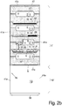
- FIG. 2b shows a solution in which the penetration openings 5 are kept substantially smaller and thus the products lying behind it in the storage space 2 and removal space 4 products are much better hygienic protection.
- the lateral, free-ending legs are made wider and the connecting middle leg, and in particular, such a transition plate 11' instead of H-shaped and U-shaped, since a bulge only at one of the two horizontal, transverse edges of the transition front panel 11 ' is sufficient to produce a narrow tool opening 14 .
- FIG. 2b is also at a position in the left half of the picture instead of a penetration opening 5, which is large enough that a user 100 can reach through with the hand 101 and also a hand holding a product P 101 , only a much smaller and especially lower in height Tool opening 14 between two adjacent transition front panels 11 is shown.
- a tool 37 for example, a slider 33 which can extend with its stem through, with the located at the front end of the stem spoon part or slide part, the product P in the interior of the storage space. 2 to be able to handle what later on the basis of FIG. 6a . b will be explained.
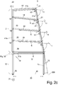
- Figure 2c shows in the side view analogous to FIG. 1 a is a front side design in which on the front side 3 in the storage area 2 ', the individual storage spaces 2 are completely closed by individual designed as flaps supply front panels 11 .
- Each formed as a flap front panel 11 is pivotable about a horizontal pivot axis 47 relative to the base frame 19, in particular the two lateral front upright sections 41 a, in particular so that it remains in the open state at least for a while or can be engaged.
- Figure 2c is also - which is independent of the design of the front - a rear side of the output rack 1, so the frame 19, closing rear door 10 shown extending in height over the height of the storage area 2 ' or above this height from a or may consist of several parts, and may also be formed in the view from the rear as a single-leaf or double-wing tailgate.
- an optional power supply unit 43 located in the base space 2 , which is preferably located near the front base front flap 16 and usually on Rack 19 is attached, and all electrical consumers that are present in the output shelf 1, powered.
- FIG. 6a . b show solutions with each separate and juxtaposed pantry 2 on the one hand and removal chamber 4 on the other hand, which are formed in two juxtaposed base frames 19 on the one hand and 19 ' on the other hand, which are directly juxtaposed and preferably secured against each other.
- the two base frame 19 and 19 ' may be formed as described above in the same manner, but is usually the base frame 19' in which the in FIG. 6a b shown removal chamber 4 is - of which, as in the FIGS. 1a to 2c one above the other several and always at the same height as the adjacent storage room 2 are located - much narrower, about one third as wide as the storage base frame 19th
- the stem of a tool 37 projects outwards, where the user 100 can grasp it by hand and with the front end of the spoon 33 - as in FIG. 6 shown - a product P from the storage space 2 in the adjacent removal chamber 4 can slide over the support bar 18 ' away, on which on one side the partition element 6, here the bearing shell, rests and on the other hand, the slightly lower removal tray 7 is attached.
- the product P must therefore first be pushed upwards from the storage position by means of the spoon 33 along the lateral ramp 8 of the bearing shell 6 and then slips over the obliquely from the storage space 2 to the removal chamber 4 sloping edge of this special support bar 18 ', so that it comes to rest on the removal tray 7 .
- a recourse protection device 9 which may either be attached to the underside of a support bar 18' or between the front and rear upright 41 a of the base frame 19 or 19 ', between which also Support strips 18 'are attached.
- Accessory protection device 9 illustrated by way of example at the top has the effect that products P can only be displaced from storage space 2 into removal space 4 , but not vice versa, by pivot bars 48 being pivotable about a pivot axis 49 extending in the depth direction 30 along the entire depth direction 30 ,
- a stop 51 which extends at a distance above the pivot axis 49
- of the pivot axis 49 downwardly projecting part of the pivoting arm 48 can be pivoted from its vertical position only very slightly to the right in the direction of the storage space 2 , at least too little a pushed from the removal chamber 4 against it against product P to spend again in the storage room 2 .
- the distance between the lower end of the swivel bracket 48 and the support bar 18 ' is too low for this purpose.
- the extraction spaces 4 are freely accessible from the front side 3 , so that the user 100 can extract therefrom his product P, but only the specifically selected product P, ie, for example, touch no product in the removal space 4 by hand and then into the storage space 2 can move back.
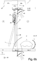
- FIG. 6b shows a to the recourse protection device 9 of FIG. 6a analogous device, but instead of the swivel bracket 48 a pivotable side plate 20 is present, which closes the side surface of a floor in the base frame 19 substantially.
- this recourse protection device 9 which is mounted between two upright profiles 41a , preferably can be easily inserted and removed from these by placing in the sheet, which on each of the mutually facing side surfaces of an upright profile 41a can be fixed and which carries to the other, front or rear, upright profile 41a indicative pivot axis 49 , an L-shaped, open to the side, recess 57 , with which it on the respective Aufrechtprofil 41a projecting stop 51 is suspended.
- FIG. 6b as a separating element 6 in contrast to the illustration of FIG. 6a not shown a normal bush, but a flat heating plate 60 or cooling plate 60th
- the heating plate 60 extends in the width direction 31 further outward than the bearing shell, namely, approximately to the outer edge of the uprights 41a, so why to remove such a heating plate 60, for example, to the rear, such a heating plate 60 according to the double arrow first in viewed obliquely from the front, so that it can be moved between the widthwise 31 upright profiles 41a .
- the side plate 20 of the recourse protection device 9 is located in the width region of the upright 41a , when the edge portion of the heating plate 60 is raised, it would collide with the lower end of the side plate 20 .
- this pivotable side plate 20th may not even be used as a recourse protection device, but only to allow the tilting and lifting the hot plate 60 , even if in addition to the corresponding pantry 2 either no other base frame or a base frame also contained therein pantries 2, not with a removal room 4, located.
- the side plate 20 can also be fastened to the base frame 19 non-pivotably, in particular fixedly.
- the support strips 18 are also according FIG. 6b differently formed than in the embodiment according to FIG. 6a for normal bearings 6: Viewed in the depth direction 30 , the main part of the support bar 18 is a sheet metal profile 61, which is designed approximately V-shaped with pointing to the center of the output shelf 1 tip.
- the upper leg 61a extends substantially horizontally from - in the assembled state - about the outer edge of the upright profile 41a towards the shelf center and is inclined slightly towards the tip down only in its area near the top and the transition to the lower leg 61b .
- the lower leg 61b extends at an angle of about 45 ° obliquely outwards and downwards, and is formed horizontally extending only in a region close to the tip. In the oblique region, a light strip 40 , which likewise extends in the depth direction 30 , can be fastened to the underside of this lower limb 61b .
- this V-shaped sheet metal profile 61 is in each case an associated ringlasche 62 forward and backward before, which serves the screwing to each one of the inwardly facing side surfaces of the front and rear upright profile 41a .
- a recess extends into this leg, which preferably extends along almost the entire length of this leg in profile direction. This prevents - especially with two adjacent, adjacent V-shaped sheet metal profiles 61 due to two adjacent base frames - that form deposits on the lower leg. In addition, the accessibility to the interior of the V-shaped sheet-metal profile 61 is facilitated by this recess, for example, for cleaning.
- the connecting sleeve 36 is a two upright profiles 41a enclosing, preferably circumferentially closed profile, with two rectangular profiles as upright profile 41 a also a - then at least twice as large in terms of the inner free space - rectangular profile.
- the two base frames 19, 19 ' must be set in this connection sleeve 36 when setting up with the lower ends of their adjacent upright profiles 41a .
- the two adjacent upright profile 41a can be connected to one another by connecting straps screwed on from behind, U-clamps plugged on via two adjacent upright profiles 41a or depth profiles 41b , or the like.
- the lower end of the uprights 41 a is usually each equipped with a adjustable foot 34 , from the base plate a threaded rod projects vertically upwards, which is screwed into a nut rotatably in the lower end of the upright profile 41 a is attached , for example, pressed or glued.
- the base frame By screwing the adjustable foot 34 , the base frame can be adjusted horizontally.
- the adjustable foot 34 viewed in the plan view is not larger than the outer contour of the cross section of the upright profile 41 a.
- the lower end of a single upright profile 41 a with it attached adjustable foot 34 with only this one adjusting foot 34 and only this one lower end receiving protective sleeve according to FIG. 5a Be surrounded, which also surrounds the upright profile 41 a small distance, and is preferably rectangular in cross-section.
- the protective sleeve 35 is seated by gravity - as well as the connecting sleeves 36 - on the substrate 200 so that it can be cleaned well around, while in the absence of protective sleeve 35 cleaning up to the threaded pin 34 of the adjustable foot 34 zoom is never completely possible.
- a front price tag unit 50 by the cross bar 17 between the two front upright profiles 41 a is hung - which can serve as a front stop for the bearing shell 6 - and at the turn a front price tag holder 23 hooked can be.
- This is preferably a plastic profile, as in FIG. 4b shown:
- the front price tag holder 23 is a plastic plate which is bent at one end edge by about 180 ° , so that there is a narrow narrow, upwardly open pocket between the two legs, in which the price tag 24 can be adjusted.
- the opposite edge of the plastic plate is bent three times by about 90 ° , so that an almost closed, downwards not completely closed, rectangular profile is formed, in which the cross section of the transverse bar 17, which also has a rectangular cross-section, fits.
- this triple offset can be bent so far that the price tag holder 23 can be pushed from above over the cross bar 17 and the free end of the three-cranked upper portion of the price tag holder 23 then snapped under the lower edge of the cross bar 17 .
- the front price tag holder 23 may, but need not, extend over the entire width, that is to say the longitudinal extent of the transverse rod 17 in the transverse direction 31 .
- the price tag holder 23 may in its first and second cranked leg of the upper portion at least one vertical slit, which is wide enough to receive the stud 52 therein and thereby achieve a fixation in the transverse direction 31 .
- the output shelves 1 are to be filled from the rear side 22 of the base frame 19 , it makes sense if the output shelves 1 also on their rear side 22 on each floor a rear price plate unit 50 ' according to Figure 2d have with a rear price tag holder 23 ' for inserting a price tag 24 so that the operator can see on which floor, so on which separating element 6, which type of product P must be placed.
- a rear price tag holder 23 ' for inserting a price tag 24 so that the operator can see on which floor, so on which separating element 6, which type of product P must be placed.
- the operator primarily the product type indicated on the price tag and less the price is relevant, but it is still present, since thereby the same price tag 24 as on the front 3 can be used.
- the rear price-sign unit 50 ' comprises a support profile 64, which is usually made of metal, and extends horizontally in the width direction between the rear left and rear right upright profile 41a and attached to a likewise extending in the width direction 31 transverse bar 17' , preferably screwed, which is respectively fixed between the rear upright profiles 41a at or slightly below the height of each of the rear end of one of the partition members 6th
- the support section 64 - usually a sheet metal bent part - a top leg 64a, which is vertically mounted on the front of the cross bar 17 ' , and the free-ending leg of an upwardly open U-shaped profile part , which protrudes from this in the depth direction 30 front, free-ending leg of this profile part from the cross bar 17 ' to the rear.
- the other, rear, free-ending U-leg 64b of this U-shape is shorter, so does not protrude as far up as the front leg 64a, and continues from its upper end by a 180 ° bend in one of this bend down vertically or obliquely downwardly behind supporting leg 64c, which has at its lower end an approximately semicircular bend up and forward in the direction of the cross bar 17 ' as a conclusion
- this support leg 64c of the rear price tag holder 23 ' can be snapped, which is also a running in the transverse direction 31 profile, but consisting of elastic plastic, by this approximately U-shaped, upwardly open price tag holder 23' at the upper end of his front freely ending leg 23'a has a crank to the front and bottom, which can embrace the upper 180 ° bend of the support leg 64c and in the lower part of its front free end leg - at least in the end regions of its extension direction - one forward and top directed lower crank at the appropriate distance from the upper crank, so that the lower crank may include the semicircular lower bend at the lower end of the support leg 64c and thereby the price tag holder 23 ' is disengaged on the support leg.
- the price tag holder 23' is protected against objects approaching from behind, such as a broom, in addition between the carrier profile 64 and the rear transverse bar 17 '.
- a stop bar 58 - preferably in turn made as a sheet metal bent part - is screwed.
- This consists of an upper, vertically and parallel to the cross bar 17 ' extending mounting leg, at the lower end integrally connects the upper end of an approximately horizontally lying V-profile, which projects backwards over the rear price tag holder 23' and extends below, wherein the upper leg of the V-profile sloping obliquely back down, so that no crumbs can be deposited on it, and the lower leg extends approximately horizontally in the depth direction 30 to the front.
- the roof rail 59 and the stop bar 58 could also be integrally formed together, but then on each floor and the lower stop bar 58 is present, which is not absolutely necessary.
- FIGS. 7a and b Special designs of the base frame 19 and the output shelf 1 created therefrom :
- the base frame 19 ' have the same structure as shown in the preceding figures and explained, however, the entire supply area 2', so the interior above the lowermost cross-profile 41c, substantially filled by a cooling module 65, the free inner cross-section - viewed from above - the base frame 19 ' substantially fills and in which it is a full forward or at least on the individual floors partially open refrigerator, on the shelves to be cooled products such as bottles or cans or cake pieces can be presented. Therefore, the base frame in this case, usually above the lowermost transverse profile 41c, only an uppermost transverse profile 41c at the upper end of the upright profiles 41a .
- the refrigeration technology is then usually arranged, preferably with a front viewable control unit and / or display unit in the base front panel 16th
- the output shelf 1 contains at the bottom of a bread slicer 66, which is on the substrate 200 and the free inner cross-section - viewed from above -. of the base frame 19 "substantially fills in the available height, bread slicer 66 extends - from means of which the customer himself their a loaf of bread taken from a dispenser shelf 1 can cut into slices - beyond the height of the base space of the base frame 19 " to almost half the height of the base frame, so that the lowermost transverse profile 41c in this base frame 19" is not present.
- a suspension rail 67 is mounted to extend in the widthwise direction 31 , on which bags 68 can be made available, in which the sliced bread can subsequently be packed.
Landscapes
- Warehouses Or Storage Devices (AREA)
- Assembled Shelves (AREA)
- Display Racks (AREA)
- Vending Machines For Individual Products (AREA)
Applications Claiming Priority (3)
| Application Number | Priority Date | Filing Date | Title |
|---|---|---|---|
| DE102016111835.4A DE102016111835A1 (de) | 2016-06-28 | 2016-06-28 | Ausgaberegal sowie Baukasten zu seiner Erstellung |
| DE202016103424.8U DE202016103424U1 (de) | 2016-06-28 | 2016-06-28 | Ausgaberegal sowie Baukasten zu seiner Erstellung |
| EP17177185.0A EP3262987B1 (fr) | 2016-06-28 | 2017-06-21 | Étagère et son kit de fabrication |
Related Parent Applications (2)
| Application Number | Title | Priority Date | Filing Date |
|---|---|---|---|
| EP17177185.0A Division-Into EP3262987B1 (fr) | 2016-06-28 | 2017-06-21 | Étagère et son kit de fabrication |
| EP17177185.0A Division EP3262987B1 (fr) | 2016-06-28 | 2017-06-21 | Étagère et son kit de fabrication |
Publications (1)
| Publication Number | Publication Date |
|---|---|
| EP3443871A1 true EP3443871A1 (fr) | 2019-02-20 |
Family
ID=59227486
Family Applications (2)
| Application Number | Title | Priority Date | Filing Date |
|---|---|---|---|
| EP18185636.0A Withdrawn EP3443871A1 (fr) | 2016-06-28 | 2017-06-21 | Système modulaire permettant de créer des étagères de distribution |
| EP17177185.0A Active EP3262987B1 (fr) | 2016-06-28 | 2017-06-21 | Étagère et son kit de fabrication |
Family Applications After (1)
| Application Number | Title | Priority Date | Filing Date |
|---|---|---|---|
| EP17177185.0A Active EP3262987B1 (fr) | 2016-06-28 | 2017-06-21 | Étagère et son kit de fabrication |
Country Status (5)
| Country | Link |
|---|---|
| US (1) | US10638855B2 (fr) |
| EP (2) | EP3443871A1 (fr) |
| DK (1) | DK3262987T3 (fr) |
| ES (1) | ES2867862T3 (fr) |
| PL (1) | PL3262987T3 (fr) |
Cited By (1)
| Publication number | Priority date | Publication date | Assignee | Title |
|---|---|---|---|---|
| USD955790S1 (en) | 2020-09-08 | 2022-06-28 | Schwarz Beschaffung GmbH | Display rack |
Families Citing this family (10)
| Publication number | Priority date | Publication date | Assignee | Title |
|---|---|---|---|---|
| EP3443871A1 (fr) * | 2016-06-28 | 2019-02-20 | Lidl Stiftung & Co. KG | Système modulaire permettant de créer des étagères de distribution |
| DE102017127163B4 (de) * | 2017-11-17 | 2020-03-05 | Lidl Stiftung & Co. Kg | Scharnier sowie Ausgabevorrichtung |
| US11965771B2 (en) * | 2018-03-30 | 2024-04-23 | Whirlpool Corporation | Beverage refrigerator with system and methods for weight detection, inventory monitoring, and overload condition notification |
| CN108903489B (zh) * | 2018-07-05 | 2021-02-09 | 黄河科技学院 | 一种家居设计效果展示装置 |
| US11320448B2 (en) | 2018-08-02 | 2022-05-03 | Logiquip Llc | Pivoting stock divider with motion detector |
| US10648998B2 (en) | 2018-08-02 | 2020-05-12 | Logiquip Llc | Automated inventory control system using pivotable divider |
| US11241103B2 (en) | 2018-10-26 | 2022-02-08 | Giles Enterprises, Inc. | LED lighting system for heated enclosure |
| CN112643637B (zh) * | 2020-12-10 | 2022-05-03 | 芜湖品金电器科技有限公司 | 一种便于取放退火片用临时存放架 |
| US12520956B2 (en) * | 2023-06-09 | 2026-01-13 | Trinity Llc | Pass-through loss prevention system |
| DE202024100668U1 (de) * | 2024-02-09 | 2025-05-13 | Wanzl GmbH & Co. KGaA | Klappeneinrichtung |
Citations (5)
| Publication number | Priority date | Publication date | Assignee | Title |
|---|---|---|---|---|
| FR2141521A1 (fr) * | 1971-06-02 | 1973-01-26 | Ipem | |
| DE202008001290U1 (de) * | 2008-01-30 | 2009-06-10 | Heinrich J. Kesseböhmer KG | Ausgabevorrichtung für Brot, Brötchen o.dgl. unverpackte Lebensmittel |
| DE202009004205U1 (de) * | 2009-03-26 | 2010-08-12 | Heinrich J. Kesseböhmer KG | Ausgabevorrichtung zur Selbstbedienungsentnahme von Brot, Brötchen o.dgl. Backwaren |
| DE202013100425U1 (de) * | 2012-11-13 | 2013-02-06 | Lidl Stiftung & Co. Kg | Ausgaberegal |
| DE202013105382U1 (de) * | 2013-01-30 | 2013-12-03 | Lidl Stiftung & Co. Kg | Ausgaberegal |
Family Cites Families (91)
| Publication number | Priority date | Publication date | Assignee | Title |
|---|---|---|---|---|
| US591739A (en) * | 1897-10-12 | Form-cabinet | ||
| US785883A (en) * | 1904-05-04 | 1905-03-28 | John A Honabarger | Vending-machine. |
| US1011112A (en) * | 1911-08-10 | 1911-12-05 | Burlingame Phillips Co | Cheese-case. |
| US1626013A (en) * | 1924-02-18 | 1927-04-26 | William T Sherer | Counter |
| US1642533A (en) * | 1926-01-28 | 1927-09-13 | James C Beer | Mail box |
| US1763716A (en) * | 1928-07-07 | 1930-06-17 | Henry G Michaelson | Show case |
| US1854104A (en) * | 1930-03-11 | 1932-04-12 | Sprague Warner & Company | Display case |
| US1999021A (en) * | 1932-12-23 | 1935-04-23 | Harry V Marsh | Display dispensing device |
| US2106839A (en) * | 1935-06-18 | 1938-02-01 | Gilbert Co A C | Merchandising display stand |
| US2136558A (en) * | 1935-09-20 | 1938-11-15 | Manshel Charles | Refrigerator |
| US2356687A (en) * | 1941-10-30 | 1944-08-22 | Charles L O'reilly | Vending machine |
| US2409117A (en) * | 1945-05-02 | 1946-10-08 | United Rexall Drug Company | Store fixture |
| US2803512A (en) * | 1956-08-06 | 1957-08-20 | Philip H Band | Multi-compartment cabinet structure |
| US2919051A (en) | 1956-12-13 | 1959-12-29 | Allen C Wideburg | Bread dispenser |
| US2940642A (en) | 1958-03-10 | 1960-06-14 | Strattman Edwin August | Dispensing bin for vegetables, etc. |
| US3911248A (en) * | 1974-12-23 | 1975-10-07 | Eugene Buday | Hot food merchandiser |
| DE3019463C2 (de) | 1980-05-21 | 1983-04-28 | Müller-Brot, GmbH, 8000 München | Verkaufsvorrichtung |
| DE3223804C1 (de) | 1982-06-25 | 1984-03-15 | Müller-Brot, GmbH, 8000 München | Selbstbedienungs-Ausgabevorrichtung |
| USD301419S (en) | 1986-12-08 | 1989-06-06 | The Pace Collection, Inc. | Cabinet |
| GB2226013A (en) | 1988-02-26 | 1990-06-20 | Senhill Pty Ltd | Dispensing apparatus |
| US5895111A (en) * | 1992-04-08 | 1999-04-20 | Anthony's Manufacturing Company, Inc. | Display case with lens lighting system |
| DE9205290U1 (de) | 1992-04-16 | 1992-07-30 | Meisterbäckerei Lechtermann GmbH & Co. Besitzgesellschaft, 4800 Bielefeld | Verkaufstresen für Backwaren |
| DE9305088U1 (de) | 1993-04-02 | 1993-10-14 | Michael Kasischke Know How und Unternehmens-Vermittlung, 10827 Berlin | Austauschbarer, kippbarer, stapelbarer Transportbehälter für unterschiedlich fließfähiges und/oder schüttfähiges Gut wie Schutt, Abfall u.dgl. |
| ATE146753T1 (de) | 1993-04-02 | 1997-01-15 | Michael Kasischke | Austauschbarer, kippbarer, stapelbarer transportbehälter für das getrennte sammeln von unterschiedlichem, fliessfähigem und/oder schüttfähigem gut wie schutt, abfall und dergleichen |
| DE4412503A1 (de) | 1994-04-12 | 1995-10-19 | Guetermann & Co | Verkaufsgerät |
| US5447366A (en) * | 1994-04-19 | 1995-09-05 | Cole; Lawrence N. | Apparatus for dispensing discrete articles |
| DE9412893U1 (de) | 1994-08-10 | 1995-09-07 | HYMER-LEICHTMETALLBAU GMBH & CO. KG, 88239 Wangen | Stellwand für Ausstellungszwecke |
| US5593048A (en) * | 1995-03-17 | 1997-01-14 | Dci Marketing | Product dispensing unit |
| DE29510232U1 (de) | 1995-06-23 | 1996-01-04 | Nowack, Michael, 80798 München | Selbstbedienungsregalsystem, insbesondere für Brot- und Backwaren |
| DE29510894U1 (de) | 1995-07-05 | 1995-10-12 | Karger, Peter, 88697 Bermatingen | Selbstbedienungs Brot-Brötchen-Kuchenregal |
| DE29518948U1 (de) | 1995-11-29 | 1996-01-18 | Backstube Siebrecht GmbH & Co. OHG, 33034 Brakel | Verkaufstheke |
| DE29518950U1 (de) | 1995-11-29 | 1996-01-18 | Backstube Siebrecht GmbH & Co. OHG, 33034 Brakel | Verkaufsständer |
| JP4049486B2 (ja) * | 1999-08-11 | 2008-02-20 | 三洋電機株式会社 | ショーケース |
| USD437509S1 (en) | 1999-11-19 | 2001-02-13 | Hon Technology Inc. | Rotary file cabinet |
| USD446964S1 (en) | 2000-03-18 | 2001-08-28 | Anna Alexandersson | Furniture cabinet |
| US6241328B1 (en) * | 2000-03-24 | 2001-06-05 | David Ziff | Enclosed workstation |
| GB0017278D0 (en) * | 2000-07-13 | 2000-08-30 | Alan Nuttall Limited | A heated food storage and display cabinet |
| NO320034B1 (no) * | 2000-09-30 | 2005-10-10 | Fritz Hakemann | Levocetirizine |
| DE20104106U1 (de) | 2001-03-08 | 2001-06-13 | EUREKA Annegret Drüke GmbH, 37671 Höxter | Verkaufseinrichtung für einzelstückige Waren |
| EP1367923B1 (fr) * | 2001-03-16 | 2008-07-23 | Stephen William Clarke | Dispositif de distribution |
| DE20114012U1 (de) | 2001-08-24 | 2001-11-08 | B & B Metall- u. Kunststoffverarbeitung GmbH, 42279 Wuppertal | Präsentationsbehälter für Lebensmittel |
| USD480429S1 (en) | 2002-07-19 | 2003-10-07 | Richard R. Koebbe | Publication vending cabinet |
| US7036947B2 (en) * | 2002-10-02 | 2006-05-02 | Carrier Commercial Refrigeration, Inc. | Refrigeration system having rear light source with reflector |
| DE10318279B4 (de) | 2003-04-17 | 2006-07-20 | Die Backfabrik Gmbh | Vorrichtung zur manuellen Entnahme von Gegenständen |
| US8047385B2 (en) * | 2004-02-03 | 2011-11-01 | Rtc Industries, Inc. | Product securement and management system |
| DE202004009530U1 (de) | 2004-06-16 | 2004-09-23 | Conteyor Multibag Systems N.V. | Transportbehälter mit schwenkbarer Trennvorrichtung |
| US20060180602A1 (en) | 2004-12-09 | 2006-08-17 | Gunther Hertel | Removal configuration |
| DE102005005193B4 (de) | 2005-02-03 | 2018-10-11 | R. Weiss Verpackungstechnik Gmbh & Co. Kg | Einrichtung mit einer Vorrichtung zur Lagerung, Behandlung und Ausgabe von Lebensmitteln |
| DE202005008527U1 (de) | 2005-05-30 | 2006-10-12 | Wanzl Metallwarenfabrik Gmbh | Verkaufstheke |
| DE202005009376U1 (de) | 2005-06-14 | 2005-09-15 | Aldi Einkauf Gmbh & Co Ohg | Ausgabeeinheit für insbesondere Brötchen |
| US7828158B2 (en) * | 2005-07-14 | 2010-11-09 | Displays Plus, Inc. | Merchandise dispensing apparatus providing theft deterrence |
| DE102005049193B4 (de) | 2005-10-07 | 2009-09-17 | Wiesheu Gmbh | Vorrichtung zur Ausgabe von Lebensmittelprodukten, insbesondere Backwaren |
| US20070138167A1 (en) * | 2005-12-21 | 2007-06-21 | Nitai Friedman | Heated food warmer |
| DE102006013435B4 (de) | 2006-03-14 | 2008-03-13 | Wiesheu Gmbh | Vorrichtung zur Ausgabe von Lebensmittelprodukten, insbesondere Backwaren |
| US20080006591A1 (en) * | 2006-07-05 | 2008-01-10 | Unique Store Fixtures Ltd. | Display case system |
| JP2008167927A (ja) * | 2007-01-11 | 2008-07-24 | Sanden Corp | ショーケース |
| DE202007006139U1 (de) | 2007-04-28 | 2008-09-11 | Heinrich J. Kesseböhmer KG | Warenbehälter zur Selbstbedienungsentnahme |
| US20080277361A1 (en) * | 2007-05-07 | 2008-11-13 | The Coca-Cola Company | Dispenser with LED Lighting |
| JP5124176B2 (ja) * | 2007-06-11 | 2013-01-23 | 三洋電機株式会社 | ショーケース |
| DE202007009953U1 (de) | 2007-07-17 | 2008-11-20 | Heinrich J. Kesseböhmer KG | Warenbehälter zur Selbstbedienungsentnahme |
| DE202007014304U1 (de) | 2007-10-12 | 2007-12-27 | Fichtner, Klaus | Vorratsbehälter zur Selbstbedienung für Stückgüter |
| USD593771S1 (en) | 2008-11-14 | 2009-06-09 | P.S. Pibbs, Inc. | Beauty salon cabinet |
| DE202009004271U1 (de) | 2009-04-01 | 2009-09-03 | Ligneus Gmbh | Zeitversetzte Klappendämpfung zur Selbstbedienungsentnahme |
| DE202009006327U1 (de) | 2009-05-04 | 2009-07-16 | Aldi Einkauf Gmbh & Co. Ohg | Entnahmevorrichtung |
| DE202009006328U1 (de) | 2009-05-04 | 2009-07-16 | Aldi Einkauf Gmbh & Co. Ohg | Entnahmevorrichtung für Lebensmittelprodukte |
| DE202009008829U1 (de) | 2009-06-26 | 2009-09-24 | Aldi Einkauf Gmbh & Co. Ohg | Entnahmevorrichtung für Lebensmittelprodukte |
| USD667234S1 (en) | 2011-06-10 | 2012-09-18 | Plug-In Storage Systems, Inc. | Cabinet |
| GB2492998B (en) * | 2011-07-20 | 2013-12-18 | Victor Mfg Ltd | A refrigerated display cabinet |
| DE202011104060U1 (de) | 2011-08-04 | 2012-11-07 | Kesseböhmer Holding OHG | Ausgabevorrichtung für Brot, Brötchen o. dgl.unverpackte Waren |
| DE202011104571U1 (de) | 2011-08-16 | 2011-11-10 | Manfred Staubach | Leuchte mit variabler Lichtposition |
| DE102011113339A1 (de) | 2011-09-15 | 2013-03-21 | Wanzl Metallwarenfabrik Gmbh | Warenbehälter |
| DE202011106702U1 (de) | 2011-10-12 | 2013-01-25 | Kesseböhmer Holding e.K. | Ausgabevorrichtung für Brot, Brötchen o. dgl. unverpackte Waren |
| WO2013062830A2 (fr) * | 2011-10-24 | 2013-05-02 | Manitowoc Foodservice Companies, Llc | Affichage et procédé de support pour étages multiples |
| USD675040S1 (en) | 2012-01-04 | 2013-01-29 | Freeosk Marketing, Inc. | Kiosk |
| GB2509207B (en) * | 2012-11-06 | 2014-11-05 | Alan Nuttall Ltd | Open fronted cabinet |
| DE202012012003U1 (de) * | 2012-12-14 | 2014-03-19 | Kesseböhmer Holding e.K. | Vorrichtung zur Selbstbedienungsentnahme von Backwaren |
| US8944260B2 (en) | 2013-02-19 | 2015-02-03 | Target Brands, Inc. | Free-standing display fixture |
| DE202013010353U1 (de) | 2013-11-18 | 2015-02-19 | Kesseböhmer Holding e.K. | Warenausgabeeinheit zur Selbstbedienungsentnahme von Backwaren |
| USD726455S1 (en) | 2014-04-01 | 2015-04-14 | Lothar Collini | Wine cabinet |
| USD775871S1 (en) | 2014-04-23 | 2017-01-10 | Innerworkings, Inc. | Temporary display rack |
| USD747901S1 (en) | 2014-09-09 | 2016-01-26 | Redpost, Inc. | Periodical stand with monitor |
| USD752372S1 (en) | 2015-01-06 | 2016-03-29 | International Paper Company | Display rack |
| JP6528452B2 (ja) * | 2015-02-23 | 2019-06-12 | 富士電機株式会社 | ショーケース |
| CA164201S (en) | 2015-03-12 | 2016-04-18 | Grupo Bimbo Sab De Cv | Product display rack |
| USD818605S1 (en) | 2016-05-16 | 2018-05-22 | Medtronic, Inc. | Dialysis recharger cabinet |
| EP3443871A1 (fr) * | 2016-06-28 | 2019-02-20 | Lidl Stiftung & Co. KG | Système modulaire permettant de créer des étagères de distribution |
| USD798635S1 (en) | 2016-08-02 | 2017-10-03 | Beeline Group, Llc | Upright merchandise display rack |
| USD814215S1 (en) | 2016-11-10 | 2018-04-03 | Ningbo Rotor Electrical Appliances Co., Ltd. | Wine cabinet |
| USD817039S1 (en) | 2017-01-31 | 2018-05-08 | Jeffrey Adolph | Toy box |
| USD839639S1 (en) | 2017-03-03 | 2019-02-05 | Herman Miller, Inc. | Cabinet |
| USD837576S1 (en) | 2017-03-23 | 2019-01-08 | Kellogg Company | Display rack |
-
2017
- 2017-06-21 EP EP18185636.0A patent/EP3443871A1/fr not_active Withdrawn
- 2017-06-21 PL PL17177185T patent/PL3262987T3/pl unknown
- 2017-06-21 ES ES17177185T patent/ES2867862T3/es active Active
- 2017-06-21 EP EP17177185.0A patent/EP3262987B1/fr active Active
- 2017-06-21 DK DK17177185.0T patent/DK3262987T3/da active
- 2017-06-22 US US15/630,531 patent/US10638855B2/en active Active
Patent Citations (5)
| Publication number | Priority date | Publication date | Assignee | Title |
|---|---|---|---|---|
| FR2141521A1 (fr) * | 1971-06-02 | 1973-01-26 | Ipem | |
| DE202008001290U1 (de) * | 2008-01-30 | 2009-06-10 | Heinrich J. Kesseböhmer KG | Ausgabevorrichtung für Brot, Brötchen o.dgl. unverpackte Lebensmittel |
| DE202009004205U1 (de) * | 2009-03-26 | 2010-08-12 | Heinrich J. Kesseböhmer KG | Ausgabevorrichtung zur Selbstbedienungsentnahme von Brot, Brötchen o.dgl. Backwaren |
| DE202013100425U1 (de) * | 2012-11-13 | 2013-02-06 | Lidl Stiftung & Co. Kg | Ausgaberegal |
| DE202013105382U1 (de) * | 2013-01-30 | 2013-12-03 | Lidl Stiftung & Co. Kg | Ausgaberegal |
Cited By (1)
| Publication number | Priority date | Publication date | Assignee | Title |
|---|---|---|---|---|
| USD955790S1 (en) | 2020-09-08 | 2022-06-28 | Schwarz Beschaffung GmbH | Display rack |
Also Published As
| Publication number | Publication date |
|---|---|
| US10638855B2 (en) | 2020-05-05 |
| ES2867862T3 (es) | 2021-10-21 |
| DK3262987T3 (da) | 2021-04-26 |
| EP3262987A1 (fr) | 2018-01-03 |
| PL3262987T3 (pl) | 2021-08-23 |
| EP3262987B1 (fr) | 2021-03-03 |
| US20180000259A1 (en) | 2018-01-04 |
Similar Documents
| Publication | Publication Date | Title |
|---|---|---|
| EP3262987B1 (fr) | Étagère et son kit de fabrication | |
| DE102016111835A1 (de) | Ausgaberegal sowie Baukasten zu seiner Erstellung | |
| EP2950685B1 (fr) | Étagère de distribution | |
| EP0979628B1 (fr) | Distributeur de produits | |
| DE202016103424U1 (de) | Ausgaberegal sowie Baukasten zu seiner Erstellung | |
| DE102020200830B4 (de) | Getränkeservierwagen | |
| DE202013100425U1 (de) | Ausgaberegal | |
| EP3346882A1 (fr) | Dispositif de sortie | |
| EP2127565B1 (fr) | Dispositif de distribution | |
| DE20104106U1 (de) | Verkaufseinrichtung für einzelstückige Waren | |
| AT509937B1 (de) | Kühltheke | |
| EP2441356A2 (fr) | Vitrine pour vente au détail | |
| DE102010037933A1 (de) | Einzelhandelsbedienschrank | |
| DE29518948U1 (de) | Verkaufstheke | |
| DE102009058645B4 (de) | Modul zur Warenpräsentation sowie Regal mit Modul zur Warenpräsentation | |
| DE102005057866B4 (de) | Abgabeeinrichtung für Lebensmittel | |
| EP1066781B1 (fr) | Dispositif pour la présentation et l'approvisionnement d'éléments en forme de cuvette, plus spécifiquement de cuvettes de douche | |
| AT391670B (de) | Sammel- und sortiervorrichtung fuer haushaltsabfall | |
| DE60311814T2 (de) | Küchenmöbel zur Aufnahme eines Müllbehälters | |
| EP3808224B1 (fr) | Dispositif de distribution | |
| DE9216150U1 (de) | Selbstbedienungs-Verkaufsvorrichtung für Backwaren | |
| DE102004041276B4 (de) | Ausgabeeinheit für Backwaren | |
| DE19646829C2 (de) | Schütte zur Darbietung von Waren in einem offenen Regal | |
| EP2084472A1 (fr) | Appareil frigorifique pourvu d'un support pour aliments réfrigérés amovible | |
| EP1142511A1 (fr) | Dispositif pour la reception des récipients |
Legal Events
| Date | Code | Title | Description |
|---|---|---|---|
| PUAI | Public reference made under article 153(3) epc to a published international application that has entered the european phase |
Free format text: ORIGINAL CODE: 0009012 |
|
| STAA | Information on the status of an ep patent application or granted ep patent |
Free format text: STATUS: REQUEST FOR EXAMINATION WAS MADE |
|
| 17P | Request for examination filed |
Effective date: 20180726 |
|
| AC | Divisional application: reference to earlier application |
Ref document number: 3262987 Country of ref document: EP Kind code of ref document: P |
|
| AK | Designated contracting states |
Kind code of ref document: A1 Designated state(s): AL AT BE BG CH CY CZ DE DK EE ES FI FR GB GR HR HU IE IS IT LI LT LU LV MC MK MT NL NO PL PT RO RS SE SI SK SM TR |
|
| AX | Request for extension of the european patent |
Extension state: BA ME |
|
| RAX | Requested extension states of the european patent have changed |
Extension state: ME Payment date: 20190726 Extension state: BA Payment date: 20190726 |
|
| STAA | Information on the status of an ep patent application or granted ep patent |
Free format text: STATUS: EXAMINATION IS IN PROGRESS |
|
| 17Q | First examination report despatched |
Effective date: 20190930 |
|
| P01 | Opt-out of the competence of the unified patent court (upc) registered |
Effective date: 20230519 |
|
| STAA | Information on the status of an ep patent application or granted ep patent |
Free format text: STATUS: THE APPLICATION IS DEEMED TO BE WITHDRAWN |
|
| 18D | Application deemed to be withdrawn |
Effective date: 20231011 |