EP3443940B1 - Système de transport d'endoprothèse vasculaire et ensemble de conduit associé - Google Patents
Système de transport d'endoprothèse vasculaire et ensemble de conduit associé Download PDFInfo
- Publication number
- EP3443940B1 EP3443940B1 EP17781891.1A EP17781891A EP3443940B1 EP 3443940 B1 EP3443940 B1 EP 3443940B1 EP 17781891 A EP17781891 A EP 17781891A EP 3443940 B1 EP3443940 B1 EP 3443940B1
- Authority
- EP
- European Patent Office
- Prior art keywords
- tube
- housing
- inner cannula
- cannula
- vascular stent
- Prior art date
- Legal status (The legal status is an assumption and is not a legal conclusion. Google has not performed a legal analysis and makes no representation as to the accuracy of the status listed.)
- Active
Links
Images




Classifications
-
- A—HUMAN NECESSITIES
- A61—MEDICAL OR VETERINARY SCIENCE; HYGIENE
- A61F—FILTERS IMPLANTABLE INTO BLOOD VESSELS; PROSTHESES; DEVICES PROVIDING PATENCY TO, OR PREVENTING COLLAPSING OF, TUBULAR STRUCTURES OF THE BODY, e.g. STENTS; ORTHOPAEDIC, NURSING OR CONTRACEPTIVE DEVICES; FOMENTATION; TREATMENT OR PROTECTION OF EYES OR EARS; BANDAGES, DRESSINGS OR ABSORBENT PADS; FIRST-AID KITS
- A61F2/00—Filters implantable into blood vessels; Prostheses, i.e. artificial substitutes or replacements for parts of the body; Appliances for connecting them with the body; Devices providing patency to, or preventing collapsing of, tubular structures of the body, e.g. stents
- A61F2/95—Instruments specially adapted for placement or removal of stents or stent-grafts
- A61F2/962—Instruments specially adapted for placement or removal of stents or stent-grafts having an outer sleeve
- A61F2/966—Instruments specially adapted for placement or removal of stents or stent-grafts having an outer sleeve with relative longitudinal movement between outer sleeve and prosthesis, e.g. using a push rod
-
- A—HUMAN NECESSITIES
- A61—MEDICAL OR VETERINARY SCIENCE; HYGIENE
- A61F—FILTERS IMPLANTABLE INTO BLOOD VESSELS; PROSTHESES; DEVICES PROVIDING PATENCY TO, OR PREVENTING COLLAPSING OF, TUBULAR STRUCTURES OF THE BODY, e.g. STENTS; ORTHOPAEDIC, NURSING OR CONTRACEPTIVE DEVICES; FOMENTATION; TREATMENT OR PROTECTION OF EYES OR EARS; BANDAGES, DRESSINGS OR ABSORBENT PADS; FIRST-AID KITS
- A61F2/00—Filters implantable into blood vessels; Prostheses, i.e. artificial substitutes or replacements for parts of the body; Appliances for connecting them with the body; Devices providing patency to, or preventing collapsing of, tubular structures of the body, e.g. stents
- A61F2/95—Instruments specially adapted for placement or removal of stents or stent-grafts
-
- A—HUMAN NECESSITIES
- A61—MEDICAL OR VETERINARY SCIENCE; HYGIENE
- A61F—FILTERS IMPLANTABLE INTO BLOOD VESSELS; PROSTHESES; DEVICES PROVIDING PATENCY TO, OR PREVENTING COLLAPSING OF, TUBULAR STRUCTURES OF THE BODY, e.g. STENTS; ORTHOPAEDIC, NURSING OR CONTRACEPTIVE DEVICES; FOMENTATION; TREATMENT OR PROTECTION OF EYES OR EARS; BANDAGES, DRESSINGS OR ABSORBENT PADS; FIRST-AID KITS
- A61F2/00—Filters implantable into blood vessels; Prostheses, i.e. artificial substitutes or replacements for parts of the body; Appliances for connecting them with the body; Devices providing patency to, or preventing collapsing of, tubular structures of the body, e.g. stents
- A61F2/95—Instruments specially adapted for placement or removal of stents or stent-grafts
- A61F2/9517—Instruments specially adapted for placement or removal of stents or stent-grafts handle assemblies therefor
-
- A—HUMAN NECESSITIES
- A61—MEDICAL OR VETERINARY SCIENCE; HYGIENE
- A61F—FILTERS IMPLANTABLE INTO BLOOD VESSELS; PROSTHESES; DEVICES PROVIDING PATENCY TO, OR PREVENTING COLLAPSING OF, TUBULAR STRUCTURES OF THE BODY, e.g. STENTS; ORTHOPAEDIC, NURSING OR CONTRACEPTIVE DEVICES; FOMENTATION; TREATMENT OR PROTECTION OF EYES OR EARS; BANDAGES, DRESSINGS OR ABSORBENT PADS; FIRST-AID KITS
- A61F2/00—Filters implantable into blood vessels; Prostheses, i.e. artificial substitutes or replacements for parts of the body; Appliances for connecting them with the body; Devices providing patency to, or preventing collapsing of, tubular structures of the body, e.g. stents
- A61F2/95—Instruments specially adapted for placement or removal of stents or stent-grafts
- A61F2/962—Instruments specially adapted for placement or removal of stents or stent-grafts having an outer sleeve
-
- A—HUMAN NECESSITIES
- A61—MEDICAL OR VETERINARY SCIENCE; HYGIENE
- A61F—FILTERS IMPLANTABLE INTO BLOOD VESSELS; PROSTHESES; DEVICES PROVIDING PATENCY TO, OR PREVENTING COLLAPSING OF, TUBULAR STRUCTURES OF THE BODY, e.g. STENTS; ORTHOPAEDIC, NURSING OR CONTRACEPTIVE DEVICES; FOMENTATION; TREATMENT OR PROTECTION OF EYES OR EARS; BANDAGES, DRESSINGS OR ABSORBENT PADS; FIRST-AID KITS
- A61F2210/00—Particular material properties of prostheses classified in groups A61F2/00 - A61F2/26 or A61F2/82 or A61F9/00 or A61F11/00 or subgroups thereof
- A61F2210/0014—Particular material properties of prostheses classified in groups A61F2/00 - A61F2/26 or A61F2/82 or A61F9/00 or A61F11/00 or subgroups thereof using shape memory or superelastic materials, e.g. nitinol
-
- A—HUMAN NECESSITIES
- A61—MEDICAL OR VETERINARY SCIENCE; HYGIENE
- A61F—FILTERS IMPLANTABLE INTO BLOOD VESSELS; PROSTHESES; DEVICES PROVIDING PATENCY TO, OR PREVENTING COLLAPSING OF, TUBULAR STRUCTURES OF THE BODY, e.g. STENTS; ORTHOPAEDIC, NURSING OR CONTRACEPTIVE DEVICES; FOMENTATION; TREATMENT OR PROTECTION OF EYES OR EARS; BANDAGES, DRESSINGS OR ABSORBENT PADS; FIRST-AID KITS
- A61F2250/00—Special features of prostheses classified in groups A61F2/00 - A61F2/26 or A61F2/82 or A61F9/00 or A61F11/00 or subgroups thereof
- A61F2250/0058—Additional features; Implant or prostheses properties not otherwise provided for
- A61F2250/0069—Sealing means
- A61F2250/007—O-rings
-
- A—HUMAN NECESSITIES
- A61—MEDICAL OR VETERINARY SCIENCE; HYGIENE
- A61M—DEVICES FOR INTRODUCING MEDIA INTO, OR ONTO, THE BODY; DEVICES FOR TRANSDUCING BODY MEDIA OR FOR TAKING MEDIA FROM THE BODY; DEVICES FOR PRODUCING OR ENDING SLEEP OR STUPOR
- A61M25/00—Catheters; Hollow probes
- A61M2025/0019—Cleaning catheters or the like, e.g. for reuse of the device, for avoiding replacement
-
- A—HUMAN NECESSITIES
- A61—MEDICAL OR VETERINARY SCIENCE; HYGIENE
- A61M—DEVICES FOR INTRODUCING MEDIA INTO, OR ONTO, THE BODY; DEVICES FOR TRANSDUCING BODY MEDIA OR FOR TAKING MEDIA FROM THE BODY; DEVICES FOR PRODUCING OR ENDING SLEEP OR STUPOR
- A61M25/00—Catheters; Hollow probes
- A61M25/0043—Catheters; Hollow probes characterised by structural features
- A61M25/0045—Catheters; Hollow probes characterised by structural features multi-layered, e.g. coated
- A61M2025/0046—Coatings for improving slidability
- A61M2025/0047—Coatings for improving slidability the inner layer having a higher lubricity
-
- A—HUMAN NECESSITIES
- A61—MEDICAL OR VETERINARY SCIENCE; HYGIENE
- A61M—DEVICES FOR INTRODUCING MEDIA INTO, OR ONTO, THE BODY; DEVICES FOR TRANSDUCING BODY MEDIA OR FOR TAKING MEDIA FROM THE BODY; DEVICES FOR PRODUCING OR ENDING SLEEP OR STUPOR
- A61M25/00—Catheters; Hollow probes
- A61M25/0009—Making of catheters or other medical or surgical tubes
- A61M25/0012—Making of catheters or other medical or surgical tubes with embedded structures, e.g. coils, braids, meshes, strands or radiopaque coils
-
- A—HUMAN NECESSITIES
- A61—MEDICAL OR VETERINARY SCIENCE; HYGIENE
- A61M—DEVICES FOR INTRODUCING MEDIA INTO, OR ONTO, THE BODY; DEVICES FOR TRANSDUCING BODY MEDIA OR FOR TAKING MEDIA FROM THE BODY; DEVICES FOR PRODUCING OR ENDING SLEEP OR STUPOR
- A61M25/00—Catheters; Hollow probes
- A61M25/0043—Catheters; Hollow probes characterised by structural features
- A61M25/005—Catheters; Hollow probes characterised by structural features with embedded materials for reinforcement, e.g. wires, coils, braids
Definitions
- This disclosure is categorized as a medical device and is intended to be a vascular stent delivery system. This report presents in detail the tubing system associated with this disclosure along with a manufacturing methodology.
- Stents therapy also known as minimally invasive surgery, has emerged to become a popular method for treating peripheral vascular disease because of its small incision size. This operation reduces complications and improves overall safety profile.
- Stents therapy requires a delivery system to implant vascular stents into the body.
- the delivery system is comprised of a tubing assembly, a driving assembly, and a handle.
- the tubing assembly is comprised of an outer and inner cannula between which the vascular stent lies. These portions are hollow for the guidewires to pass through.
- the driving assembly mobilizes the inner cannula longitudinally in order to deploy the stent.
- the outer cannula is fixed to the housing and the driving assembly is operably engaged with the inner cannula.
- the operator uses the guidewire to navigate the tubing assembly to the surgery site.
- the driving assembly mobilizes the inner cannula axially forward to introduce the stent into the vasculature. From there, the stent unfolds to support the inner wall of the vessel.
- a cleaning tube is incorporated in the delivery system.
- This component is located within the handle housing and is in communication with the inner cannula cavity.
- a clean fitting can be attached to the end of the cleaning tube to clean the inner cannula and its cavity after each use.
- the cleaning tube typically includes a middle steel tube coupled to the driving assembly and sleeved within the inner cannula.
- the middle steel tube is affixed to the connection part of the housing.
- the inner cannula will move relative to the middle steel tube, resulting in unwanted contact and subsequent scratching between the inner and middle steel tubes. This decreases the overall service life of the delivery system.
- a plurality of connections within the cleaning pipeline easily cause leakage of liquid at respective connection sites, resulting in liquid flowing into the driving assembly and the housing.
- FIG. 13 shows that the inner cannula 800 is formed integrally and rachets 900 are coupled to the inner cannula 800. Therefore, during introduction of the stent, the rachets are bent due to poor stiffness.
- the cone tip (TIP) of the tubing assembly is directly adherent to the inner cannula with limited joint intensity, resulting in risk of accidental detachment.
- US 20140303722A1 describes an apparatus for delivering a prosthetic heart valve into a patient by means that are less invasive than conventional open-chest, open-heart surgery.
- the prosthetic valve may be collapsed while in a delivery device.
- the valve can be released from the delivery device, which allows the valve to re-expand to the configuration in which it can function as a heart valve.
- the delivery device may be constructed to facilitate delivery of the prosthetic valve into the patient via the apex of the patient's heart.
- the invention is a vascular stent delivery system as defined by claim 1.
- the delivery system is comprised of the following: a housing, an outer cannula, a cleaning tube, an inner cannula, and a driving assembly.
- the outer cannula is attached to the first end of the housing and extends outside the housing through an opening.
- the cleaning tube is affixed to the second end of the housing and extends outward through an opening at the back.
- An inner cannula is threaded between the outer cannula and the cleaning tube. The portion of this tube within the cleaning tube is modified to prevent it from scratching the cleaning tube cavity's inner wall.
- a driving assembly a part of which is disposed within the housing and is operably engaged with a part of the inner cannula is there to move the inner cannula axially in the outer cannula and the cleaning tube.
- the method to manufacture this vascular stent delivery system is based on putting together the aforementioned components.
- the present disclosure achieves the following advantages:
- the operability of the delivery system is improved through the anti-scratching treatment between the inner and cleaning tube. This enhances the service life of the delivery system.
- the integral formation of the cleaning tube as compared with past prototypes, has a reduced risk of liquid leakage, which results in improved operability and reliability of the system.
- Figure 1 shows a vascular stent delivery system.
- This system includes a right half housing 110, a left half housing 120, an outer cannula 200, a cleaning tube 300, an inner cannula 800, and a driving assembly 400.
- the outer cannula 200 is located outside the housing and coupled to the first end 101 of the housing.
- a three-way tube 500 is attached to the first end 101 of the housing by a rubber head 600 (joint member).
- the outer cannula 200 passes through the rubber head 600 and extends to the first end 501 of the three-way tube 500 (the detailed structure thereof will be described as below) such that the outer cannula 200 is in communication with the three-way tube 500 and the rubber head 600 is fixed to the housing.
- the rubber head 600 is sandwiched in and held by the right 110 and the left half housing 120, both of which are fixed together by fitting the nut 121 with the connection feature 111 (such as screw hold).
- the rubber head 600 and the three-way tube 500 can be omitted and the outer cannula 200 can be directly fixed to the housing.
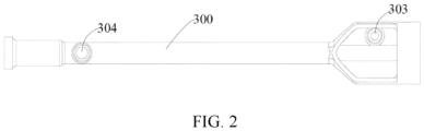
- the cleaning tube 300 cleans the delivery system once the vascular stent is transported. It is an integrally formed two-way tube, also called the LUER tube, is formed by polycarbonate (PC), and coupled to the second end 102 of the housing. The first end 301 of the cleaning tube 300 is disposed within the housing and the second end 302 extends out of the housing to the outer space.
- the cleaning tube 300 is provided with connection features 303 and 304. Connection features 113 and 114 corresponsive to the connection features 303 and 304 are disposed on the corresponding locations on the right half housing 110.
- the cleaning tube 300 is fixed to the housing by embedding connection features 303 and 304 into connection features 113 and 114. As a result, the cleaning tube 300 is held by the right 110 and left half housing 120.
- a part of the inner cannula 800 is contained within the housing, which can be formed from a steel tube (i.e. inner steel tube) but is not limited to this.
- the inner cannula 800 can be formed from other suitable materials that can be used for the vascular stent delivery system.
- the first end of the inner cannula 800 extends into the outer cannula 200.
- the inner cannula 800 is inserted into the second end 502 of the three-way tube 500. It then passes through the three-way tube 500 and extends into the cavity of the outer cannula 200.
- the three-way tube 500 can be omitted.
- the first end of the inner cannula 800 directly extends into the cavity of the outer cannula 200.
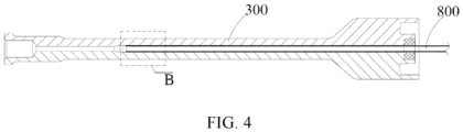
- the second end of the inner cannula extends into the cavity of the cleaning tube 300 from the first end 301 of the cleaning tube 300 ( Figure 4 and 5 ).
- a portion of the driving assembly 400 is operably engaged with the inner cannula 800 and both are affixed to the inner portion of the housing.
- the driving assembly 400 consists of a thumb drive member 401 and a guide rail 402.
- the driving assembly 400 is connected between the first and second ends of the inner cannula.
- the right half housing 110 is coupled to the driving assembly 400 through the connection features 112, 115, and 116.
- the nut 121 passes through the hole on the left half housing 120 and holes on the clamping spring 122.
- the guide rail 402 extends into the screw hole 111 on the right half housing 110.
- the left 120 and right half housing 110 are combined together by engaging the nut 121 with the screw hole 111 such that a part of the driving assembly 400 is received in the housing and, meanwhile, a part of the thumb driving member 401 is exposed out of the housing to be used by the operator.
- the inner cannula 800 passes through the guide rail 402 and is engaged with a part of the thumb-driving member 401.
- the inner cannula 800 moves along the guide rail 402 by pulling and pushing the thumb driving member 401 such that the inner cannula axially moves in the inner cavity of the outer cannula and the cleaning tube.
- the first end of the inner cannula moves in the outer cannula 200 such that the vascular stent moves along the outer cannula 200 and enters into the vessels. Thereafter, the vascular stent unfolds to support the inner wall of the vessel. Meanwhile, the second end of the inner cannula moves in the cleaning tube 300 with movement of the inner cannula as a whole.
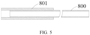
- a heat shrink tube 801 is added to the inner cannula's second end 800 to prevent scratching between the inner cannula and the cleaning tube's inner wall ( Figure 4 and 5 ).
- This tube is made of polyperfluorinated ethylene propylene (PEP) to prevent slippage. Even if there is an assembly error, the relative movement driven by pushing and pulling the inner cannula will not result in scratching of the cleaning tube's inner wall.
- the PEP has a smooth surface from the reduced frictional resistance of PC.
- the distal end of the inner cannula's second end is formed as a fillet to reduce frictional resistance between it and the cleaning tube wall. This protects the wall during use.
- the cleaning tube 300 is a part of the LUER tube and is an integrally formed two-way tube made of PC material. This ensures that the cleaning tube is leak proof, which enhances the overall operability and reliability of the system.
- the integral production method of this part lowers its overall cost.
- the distal end 302 of the cleaning tube 300 has an opening and joint cap 320 for sealing the opening. During stent deployment, the joint cap 320 occludes the opening to prevent body fluid (i.e. blood) from flowing out. Upon completion of the vascular stent transport, the joint cap 320 is opened so that the cleaning fluid can be added to the delivery system.
- a fitting 305 for the guide wire to pass through is located within the cleaning tube 300 between the first and second ends.
- the cavity of the cleaning tube at the fitting has a tapered inner diameter correlating with its gradient design. This feature is present to facilitate guidewire movement within.
- the three-way tube 500 is used for cleaning the front end, or the part adjacent to the outer cannula, of the vascular stent delivery system.
- the three-way tube can be a LUER three-way tube for the vascular stent delivery system.
- Figure 1 shows the three-way tube 500 is connected at the first end 101 of the housing, which has a first end 501 extending out from the housing to the outer space.
- a second end 501 is contained within the housing and is in communication with the first end 501.
- a third end 503 is disposed between the first 501 and second 502 ends.
- the first end 501 of the three-way tube 500 is in communication with the outer cannula 200. This end 501 is coupled to and in communication with the outer cannula 200 via the rubber head 600.
- the first end of the inner cannula is inserted into the second end 502 of the three-way tube and passes through the three-way tube 500 to extend out from the first end 501 of the three-way tube 500 into the outer cannula 200.
- the distal end of the third end 503 of the three-way end 500 has an opening and a joint cap 522 for closing this opening.
- the opening is closed by the joint cap 522 to prevent body fluid, such as blood, from flowing out.
- the joint cap 522 is opened through which the cleaning fluid is added to clean the front part of the vascular stent delivery system.
- the sealing assemblies (311, 312, 511, 512) are disposed at the distal ends of the first end 301 of the cleaning tube 300 and the second end 502 of the three-way tube 500.
- the inner cannula can pass through the sealing assemblies.
- the sealing assemblies have channels through which the inner cannula passes.
- a sealing assembly comprising an O-shaped ring 311 and a cover plate 312 for fixing such O-shaped ring is disposed at the distal end of the first end 301 of the cleaning tube 300.
- a sealing assembly comprising an O-shaped ring 511 and a cover plate 512 for fixing such an O-shaped ring is connected at the distal portion of the second end 502 of the three-way tube 500.
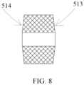
- Either or both the O-shaped rings 311 and 511 is/are configured to have the thickness gradually decreased from the center to the edge.
- two sides 513 and 514 of the O-shaped ring are present as a conical surface, respectively.
- the O-shaped ring with conical surface design cooperates with the LUER two-way and three-way tubes, and there is always a line along the circumference that exhibits interference fit with the LUER two-way or three-way tubes such that even if the inner cannula moves, the O-shaped ring with conical surface design has less axial movement than the O-shaped ring with a flat surface.
- the surface for contacting the O-shaped ring with the inner cannula is coated with a lubricating layer, comprised of any one of parylene, polytetrafluoroethylene (PTEE), polyvinylpyrrolidone (PVP) and silicone oil.
- the lubricating layer made of parylene coating.
- the O-shaped ring must exhibit interference first with the inner cannula; however, such interference fit will have influence on the delivery feel for the operator.
- the parylene coating combined with the O-shaped ring will lower friction due to the smoothness of the coating, and facilitate its use.
- the sealing assembly mentioned can be disposed at either of the first end 301 of the cleaning tube 300 or the second end 502 of the three-way tube 500.
- the sealing assembly as mentioned above can be merely disposed at the second end 502 of the three-way tube 500.
- the anti-scratching treatment between the inner cannula and cleaning tube can effectively improve the operability and service life of the vascular stent delivery system.
- the methodology for manufacturing the vascular stent delivery system is described in detail below.
- Manufacturing the vascular stent include providing a housing, an outer cannula, a cleaning tube, an inner cannula, and a driving assembly.
- the outer cannula is configured to be disposed outside the housing and attached to the first end of the housing.
- a cleaning tube is attached to the second end of the housing, the first end of which is disposed within the housing and the second end of which extends out from the housing to the outer space.
- An inner cannula, a part of which is disposed within the housing has a first end that extends into the outer cannula and a second end that extends from the cleaning tube's first end into the cleaning tube cavity.
- the driving assembly is configured so that a portion of this is contained within the housing and operably engaged with the part of the inner cannula that is disposed within the housing for driving the inner cannula to axially move in the outer cannula and the cleaning tube.
- the second end of the inner cannula's distal end is configured to prevent it from scratching the cleaning tube's inner wall. This configuration prevents scratching with cleaning tube's inner wall and provides a heat shrink tube through which the distal portion of the inner cannula's second end is inserted. The portion of the inner cannula's second end that makes contact with the heat shrink tube is subject to anti-slipping treatment. As an alternative, the distal part of the inner cannula's second end can be fixably coupled to the heat shrink tube.
- the cleaning tube is an integrally formed two-way tube made of PC material, making it relatively leak proof to improve the operability and reliability of the system. Additionally, a fitting for the guidewire to pass there through is disposed within the cleaning tube and between the first and second end of the cleaning tube. In some embodiments, the cleaning tube cavity at the fitting for guidewire has a gradually decreasing inner diameter, which pertains to a gradient design. This facilitates guidewire movement through the inner cavity and avoids the stairs and stuck phenomenon.
- an opening is disposed at the distal end of the cleaning tube's second end and provided with a joint cap for closing the opening.
- the joint cap can close the opening to prevent blood from flowing out.
- the joint cap can be opened and the cleaning fluid is then added to the vascular stent delivery system.
- This method also includes providing a three-way tube, such as the LUER tube, attached to the housing's first end and with a first end extending into the housing's outer space and a second end contained within the housing and in linear communication with the other tubing assemblies.
- the three-way tube's first end connects with the outer cannula and inserts into the second end to pass through the distal end into the outer cannula.
- the distal part of the three-way tube has an opening closed by the joint cap. As such, during transportation of the vascular stent, the opening is closed by the joint cap to prevent body fluid, such as blood, from flowing out.
- the joint cap is opened and the cleaning fluid can be added to clean the front part of the vascular stent delivery system.
- a sealing assembly is affixed to the end of at least one first end of the cleaning tube (i.e. two-way tube) and the second end of the three-way tube.
- the inner cannula can pass through the sealing assembly.
- the sealing assembly may comprise of an O-shaped ring configured to have thickness gradually decreasing from the center to the edge.
- the surface for contacting the O-shaped ring with the inner cannula is coated with a lubricating layer, which can be made of Parylene, Polytetrafluoroethylene (PTEE), Polyvinylpyrrolidone (PVP), and silicone oil.
- PTEE Polytetrafluoroethylene
- PVP Polyvinylpyrrolidone
- silicone oil silicone oil
Landscapes
- Health & Medical Sciences (AREA)
- Engineering & Computer Science (AREA)
- Biomedical Technology (AREA)
- Cardiology (AREA)
- Oral & Maxillofacial Surgery (AREA)
- Transplantation (AREA)
- Heart & Thoracic Surgery (AREA)
- Vascular Medicine (AREA)
- Life Sciences & Earth Sciences (AREA)
- Animal Behavior & Ethology (AREA)
- General Health & Medical Sciences (AREA)
- Public Health (AREA)
- Veterinary Medicine (AREA)
- Media Introduction/Drainage Providing Device (AREA)
Claims (6)
- Système de pose d'endoprothèse vasculaire comprenant :un boîtier (110, 120) ;une canule externe (200), disposée à l'extérieur du boîtier et couplée à une première extrémité (101) du boîtier (110, 120) ;caractérisé en ce qu'il comprend en outre :un tube de nettoyage (300), couplé à une seconde extrémité (102) du boîtier (110, 120), une première extrémité (301) du tube de nettoyage (300) étant disposée à l'intérieur du boîtier (110, 120) et la seconde extrémité (302) du tube de nettoyage (300) s'étendant hors du boîtier (110, 120) ;une canule interne (800), une partie de la canule interne (800) étant disposée à l'intérieur du boîtier (110, 120), et une première extrémité de la canule interne (800) étant insérée dans la canule externe (200), et la seconde extrémité de la canule interne (800) s'étendant dans une cavité du tube de nettoyage (300) depuis la première extrémité (301) du tube de nettoyage (300) ;un ensemble d'entraînement (400), une partie de l'ensemble d'entraînement (400) étant disposée à l'intérieur du boîtier (110, 120) et étant en prise fonctionnelle avec une partie de la canule interne (800) disposée à l'intérieur du boîtier (110, 120), l'ensemble d'entraînement (400) étant conçu pour entraîner la canule interne (800) de manière à la déplacer axialement dans la canule externe (200) et le tube de nettoyage (300) ; etune extrémité de la seconde extrémité de la canule interne (800) étant conçue pour empêcher l'extrémité de la seconde extrémité de la canule interne (800) de rayer la paroi interne du tube de nettoyage (300).
- Système de pose d'endoprothèse vasculaire selon la revendication 1, la configuration de l'extrémité de la seconde extrémité de la canule interne (800) permettant d'empêcher ladite extrémité de rayer la paroi interne du tube de nettoyage (300) comprenant l'insertion de l'extrémité de la seconde extrémité de la canule interne (800) dans un tube thermorétractable (801).
- Système de pose d'endoprothèse vasculaire selon l'une quelconque des revendications 1 à 2, ledit tube de nettoyage (300) étant un tube à deux voies formé d'un seul tenant.
- Système de pose d'endoprothèse vasculaire selon la revendication 3, comprenant en outre :un tube à trois voies, le tube à trois voies (500) étant disposé sur la première extrémité (101) du boîtier (110, 120), comportant une première extrémité (501) s'étendant hors du boîtier (110, 120) jusqu'à un espace externe, une deuxième extrémité (502) disposée à l'intérieur du boîtier (110, 120) et en communication linéaire avec la première extrémité (501) du tube à trois voies (500), et une troisième extrémité (503) disposée entre la première extrémité (501) du tube à trois voies (500) et la deuxième extrémité (502) du tube à trois voies (500) et s'étendant hors du boîtier (110, 120) jusqu'à l'espace externe ; etladite première extrémité (501) du tube à trois voies (500) étant en communication avec la canule externe (200), ladite première extrémité de la canule interne (800) étant insérée dans la deuxième extrémité (502) du tube à trois voies (500) et passant à travers le tube à trois voies (500) et s'étendant dans la canule externe (200) depuis la première extrémité (501) du tube à trois voies (500) ; de préférence, un ensemble d'étanchéité étant disposé au niveau de l'extrémité d'au moins une extrémité parmi la première extrémité (301) du tube de nettoyage (300) et la deuxième extrémité (502) du tube à trois voies (500), et ladite canule interne (800) passant à travers l'ensemble d'étanchéité.
- Système de pose d'endoprothèse vasculaire selon la revendication 4, ledit ensemble d'étanchéité comprenant un joint torique (311, 511) et une plaque de recouvrement (312,512) destinée à fixer le joint torique (311, 511) ; et
ledit joint torique (311, 511) comportant une épaisseur diminuant progressivement du centre vers le bord. - Système de pose d'endoprothèse vasculaire selon la revendication 4, ledit ensemble d'étanchéité comprenant un joint torique (311, 511) et une plaque de recouvrement (312, 512) destinée à fixer le joint torique (311, 511) ; et
la surface destinée à mettre en contact le joint torique (311, 511) avec la canule interne (800) comprenant une couche lubrifiante.
Applications Claiming Priority (9)
| Application Number | Priority Date | Filing Date | Title |
|---|---|---|---|
| CN201620301792.0U CN205698143U (zh) | 2016-04-12 | 2016-04-12 | 血管支架输送系统 |
| CN201620301609.7U CN205698141U (zh) | 2016-04-12 | 2016-04-12 | 血管支架输送系统及其导管组件 |
| CN201610224595.8A CN107280830B (zh) | 2016-04-12 | 2016-04-12 | 血管支架输送系统及其导管组件 |
| CN201610224890.3A CN107280828B (zh) | 2016-04-12 | 2016-04-12 | 血管支架输送系统 |
| CN201620301791.6U CN205698142U (zh) | 2016-04-12 | 2016-04-12 | 血管支架输送系统及其导管组件 |
| CN201610224686.1A CN107280831B (zh) | 2016-04-12 | 2016-04-12 | 血管支架输送系统及其导管组件 |
| CN201610224524.8A CN107280829B (zh) | 2016-04-12 | 2016-04-12 | 血管支架输送系统 |
| CN201620301833.6U CN205698144U (zh) | 2016-04-12 | 2016-04-12 | 血管支架输送系统 |
| PCT/CN2017/080216 WO2017177915A1 (fr) | 2016-04-12 | 2017-04-12 | Système de transport d'endoprothèse vasculaire et ensemble de conduit associé |
Publications (3)
| Publication Number | Publication Date |
|---|---|
| EP3443940A1 EP3443940A1 (fr) | 2019-02-20 |
| EP3443940A4 EP3443940A4 (fr) | 2020-08-19 |
| EP3443940B1 true EP3443940B1 (fr) | 2024-08-14 |
Family
ID=60041400
Family Applications (1)
| Application Number | Title | Priority Date | Filing Date |
|---|---|---|---|
| EP17781891.1A Active EP3443940B1 (fr) | 2016-04-12 | 2017-04-12 | Système de transport d'endoprothèse vasculaire et ensemble de conduit associé |
Country Status (3)
| Country | Link |
|---|---|
| US (1) | US11116651B2 (fr) |
| EP (1) | EP3443940B1 (fr) |
| WO (1) | WO2017177915A1 (fr) |
Family Cites Families (27)
| Publication number | Priority date | Publication date | Assignee | Title |
|---|---|---|---|---|
| GB0110551D0 (en) | 2001-04-30 | 2001-06-20 | Angiomed Ag | Self-expanding stent delivery service |
| US20070156223A1 (en) | 2005-12-30 | 2007-07-05 | Dennis Vaughan | Stent delivery system with improved delivery force distribution |
| JP5455633B2 (ja) | 2006-10-22 | 2014-03-26 | アイデブ テクノロジーズ インコーポレイテッド | ステント前進のためのデバイスおよび方法 |
| ES2475144T3 (es) * | 2007-06-26 | 2014-07-10 | St. Jude Medical, Inc. | Aparato para la implantación de válvulas prot�sicas de corazón replegables / expansibles |
| US8043301B2 (en) | 2007-10-12 | 2011-10-25 | Spiration, Inc. | Valve loader method, system, and apparatus |
| US8876878B2 (en) | 2010-07-23 | 2014-11-04 | Medtronic, Inc. | Attachment mechanism for stent release |
| CN102038565B (zh) | 2010-12-17 | 2013-08-14 | 北京有色金属研究总院 | 新型大血管支架放送系统 |
| CN102283728B (zh) | 2011-06-28 | 2014-09-10 | 先健科技(深圳)有限公司 | 一种管腔支架输送系统 |
| CN102488577B (zh) | 2011-12-14 | 2014-12-24 | 湖南埃普特医疗器械有限公司 | 血管内导丝定位装置及其制备方法 |
| US9011513B2 (en) | 2012-05-09 | 2015-04-21 | Abbott Cardiovascular Systems Inc. | Catheter having hydraulic actuator |
| CN103655004B (zh) | 2012-09-21 | 2015-11-25 | 上海微创医疗器械(集团)有限公司 | 植入体输送系统 |
| JP6172779B2 (ja) | 2013-03-12 | 2017-08-02 | アボット カーディオバスキュラー システムズ インコーポレイテッド | 液圧アクチュエータ及びロックシステムを有するカテーテル |
| CN203408335U (zh) | 2013-06-01 | 2014-01-29 | 深圳市凯思特精工塑料有限公司 | 一种抗菌型血管鞘 |
| CN103431926B (zh) | 2013-09-04 | 2015-09-30 | 杭州启明医疗器械有限公司 | 用于介入器械输送的鞘芯及具有该鞘芯的输送系统 |
| CN203647541U (zh) | 2013-12-27 | 2014-06-18 | 常州乐奥医疗科技有限公司 | 一种新型支架输送系统 |
| CN103961194B (zh) | 2014-05-21 | 2016-05-18 | 苏州茵络医疗器械有限公司 | 一种高回缩性血管支架输送系统 |
| CN104546243B (zh) | 2015-01-04 | 2016-05-25 | 苏州茵络医疗器械有限公司 | 单手握持式的血管支架输送系统及其使用方法 |
| CN104546246A (zh) | 2015-01-04 | 2015-04-29 | 苏州英络医疗器械有限公司 | 一种血管支架输送系统及其输送方法 |
| CN204428220U (zh) | 2015-01-04 | 2015-07-01 | 苏州英络医疗器械有限公司 | 一种血管支架输送系统 |
| CN107280829B (zh) | 2016-04-12 | 2018-10-16 | 苏州茵络医疗器械有限公司 | 血管支架输送系统 |
| CN205698143U (zh) | 2016-04-12 | 2016-11-23 | 苏州茵络医疗器械有限公司 | 血管支架输送系统 |
| CN107280830B (zh) | 2016-04-12 | 2019-02-01 | 苏州茵络医疗器械有限公司 | 血管支架输送系统及其导管组件 |
| CN205698142U (zh) | 2016-04-12 | 2016-11-23 | 苏州茵络医疗器械有限公司 | 血管支架输送系统及其导管组件 |
| CN107280831B (zh) | 2016-04-12 | 2019-02-01 | 苏州茵络医疗器械有限公司 | 血管支架输送系统及其导管组件 |
| CN205698141U (zh) | 2016-04-12 | 2016-11-23 | 苏州茵络医疗器械有限公司 | 血管支架输送系统及其导管组件 |
| CN205698144U (zh) | 2016-04-12 | 2016-11-23 | 苏州茵络医疗器械有限公司 | 血管支架输送系统 |
| CN107280828B (zh) | 2016-04-12 | 2019-02-01 | 苏州茵络医疗器械有限公司 | 血管支架输送系统 |
-
2017
- 2017-04-12 WO PCT/CN2017/080216 patent/WO2017177915A1/fr not_active Ceased
- 2017-04-12 US US16/093,619 patent/US11116651B2/en not_active Expired - Fee Related
- 2017-04-12 EP EP17781891.1A patent/EP3443940B1/fr active Active
Also Published As
| Publication number | Publication date |
|---|---|
| US11116651B2 (en) | 2021-09-14 |
| WO2017177915A1 (fr) | 2017-10-19 |
| US20190125563A1 (en) | 2019-05-02 |
| EP3443940A1 (fr) | 2019-02-20 |
| EP3443940A4 (fr) | 2020-08-19 |
Similar Documents
| Publication | Publication Date | Title |
|---|---|---|
| AU2020216121B2 (en) | Internal balloon sheath | |
| US5098406A (en) | Anti-reflux, low friction, skirted hemostasis valve and introducer | |
| US12239814B2 (en) | Methods and devices for vascular access | |
| US7736355B2 (en) | Intravascular foreign matter suction assembly | |
| US11986607B2 (en) | Catheter structure with improved support and related systems, methods, and devices | |
| US9308352B2 (en) | Retention member and application thereof | |
| US11033713B2 (en) | Catheter hubs and valves for minimizing embolic potential | |
| EP2990071B1 (fr) | Corps allongé médical | |
| US20130331692A1 (en) | Medical connector | |
| US20070293887A1 (en) | Catheter assembly | |
| US20160096002A1 (en) | Segmented Catheter Structure and Improved Catheter Tip and Related Systems, Methods, and Devices | |
| JP2010530785A5 (fr) | ||
| CN102802561A (zh) | 阀装载器方法、系统和设备 | |
| US11992634B2 (en) | Arterial access needle with proximal port | |
| US20230201524A1 (en) | Catheter assembly | |
| JP5897408B2 (ja) | ステントデリバリーカテーテル | |
| EP3991777A1 (fr) | Cathéter à ballon | |
| US9636478B2 (en) | Medical tube | |
| JP2022148511A (ja) | カテーテル | |
| JP2019154903A (ja) | カテーテル組立体 | |
| CN205698144U (zh) | 血管支架输送系统 | |
| CN107280829B (zh) | 血管支架输送系统 | |
| US11116651B2 (en) | Vascular stent delivery system and tubing assembly thereof | |
| CN117752923A (zh) | 医疗导管 | |
| US20250281732A1 (en) | Methods and devices for vascular access |
Legal Events
| Date | Code | Title | Description |
|---|---|---|---|
| STAA | Information on the status of an ep patent application or granted ep patent |
Free format text: STATUS: THE INTERNATIONAL PUBLICATION HAS BEEN MADE |
|
| PUAI | Public reference made under article 153(3) epc to a published international application that has entered the european phase |
Free format text: ORIGINAL CODE: 0009012 |
|
| STAA | Information on the status of an ep patent application or granted ep patent |
Free format text: STATUS: REQUEST FOR EXAMINATION WAS MADE |
|
| 17P | Request for examination filed |
Effective date: 20181112 |
|
| AK | Designated contracting states |
Kind code of ref document: A1 Designated state(s): AL AT BE BG CH CY CZ DE DK EE ES FI FR GB GR HR HU IE IS IT LI LT LU LV MC MK MT NL NO PL PT RO RS SE SI SK SM TR |
|
| AX | Request for extension of the european patent |
Extension state: BA ME |
|
| DAV | Request for validation of the european patent (deleted) | ||
| DAX | Request for extension of the european patent (deleted) | ||
| RIC1 | Information provided on ipc code assigned before grant |
Ipc: A61F 2/966 20130101ALI20200227BHEP Ipc: A61F 2/95 20130101AFI20200227BHEP |
|
| A4 | Supplementary search report drawn up and despatched |
Effective date: 20200721 |
|
| RIC1 | Information provided on ipc code assigned before grant |
Ipc: A61F 2/966 20130101ALI20200715BHEP Ipc: A61F 2/95 20130101AFI20200715BHEP |
|
| GRAP | Despatch of communication of intention to grant a patent |
Free format text: ORIGINAL CODE: EPIDOSNIGR1 |
|
| STAA | Information on the status of an ep patent application or granted ep patent |
Free format text: STATUS: GRANT OF PATENT IS INTENDED |
|
| INTG | Intention to grant announced |
Effective date: 20240314 |
|
| GRAS | Grant fee paid |
Free format text: ORIGINAL CODE: EPIDOSNIGR3 |
|
| GRAA | (expected) grant |
Free format text: ORIGINAL CODE: 0009210 |
|
| STAA | Information on the status of an ep patent application or granted ep patent |
Free format text: STATUS: THE PATENT HAS BEEN GRANTED |
|
| AK | Designated contracting states |
Kind code of ref document: B1 Designated state(s): AL AT BE BG CH CY CZ DE DK EE ES FI FR GB GR HR HU IE IS IT LI LT LU LV MC MK MT NL NO PL PT RO RS SE SI SK SM TR |
|
| REG | Reference to a national code |
Ref country code: GB Ref legal event code: FG4D |
|
| REG | Reference to a national code |
Ref country code: CH Ref legal event code: EP |
|
| REG | Reference to a national code |
Ref country code: DE Ref legal event code: R096 Ref document number: 602017084088 Country of ref document: DE |
|
| REG | Reference to a national code |
Ref country code: IE Ref legal event code: FG4D |
|
| REG | Reference to a national code |
Ref country code: LT Ref legal event code: MG9D |
|
| REG | Reference to a national code |
Ref country code: NL Ref legal event code: MP Effective date: 20240814 |
|
| PG25 | Lapsed in a contracting state [announced via postgrant information from national office to epo] |
Ref country code: NO Free format text: LAPSE BECAUSE OF FAILURE TO SUBMIT A TRANSLATION OF THE DESCRIPTION OR TO PAY THE FEE WITHIN THE PRESCRIBED TIME-LIMIT Effective date: 20241114 |
|
| REG | Reference to a national code |
Ref country code: AT Ref legal event code: MK05 Ref document number: 1712588 Country of ref document: AT Kind code of ref document: T Effective date: 20240814 |
|
| PG25 | Lapsed in a contracting state [announced via postgrant information from national office to epo] |
Ref country code: PL Free format text: LAPSE BECAUSE OF FAILURE TO SUBMIT A TRANSLATION OF THE DESCRIPTION OR TO PAY THE FEE WITHIN THE PRESCRIBED TIME-LIMIT Effective date: 20240814 Ref country code: FI Free format text: LAPSE BECAUSE OF FAILURE TO SUBMIT A TRANSLATION OF THE DESCRIPTION OR TO PAY THE FEE WITHIN THE PRESCRIBED TIME-LIMIT Effective date: 20240814 Ref country code: NL Free format text: LAPSE BECAUSE OF FAILURE TO SUBMIT A TRANSLATION OF THE DESCRIPTION OR TO PAY THE FEE WITHIN THE PRESCRIBED TIME-LIMIT Effective date: 20240814 Ref country code: PT Free format text: LAPSE BECAUSE OF FAILURE TO SUBMIT A TRANSLATION OF THE DESCRIPTION OR TO PAY THE FEE WITHIN THE PRESCRIBED TIME-LIMIT Effective date: 20241216 Ref country code: GR Free format text: LAPSE BECAUSE OF FAILURE TO SUBMIT A TRANSLATION OF THE DESCRIPTION OR TO PAY THE FEE WITHIN THE PRESCRIBED TIME-LIMIT Effective date: 20241115 |
|
| PG25 | Lapsed in a contracting state [announced via postgrant information from national office to epo] |
Ref country code: BG Free format text: LAPSE BECAUSE OF FAILURE TO SUBMIT A TRANSLATION OF THE DESCRIPTION OR TO PAY THE FEE WITHIN THE PRESCRIBED TIME-LIMIT Effective date: 20240814 |
|
| PG25 | Lapsed in a contracting state [announced via postgrant information from national office to epo] |
Ref country code: LV Free format text: LAPSE BECAUSE OF FAILURE TO SUBMIT A TRANSLATION OF THE DESCRIPTION OR TO PAY THE FEE WITHIN THE PRESCRIBED TIME-LIMIT Effective date: 20240814 |
|
| PG25 | Lapsed in a contracting state [announced via postgrant information from national office to epo] |
Ref country code: AT Free format text: LAPSE BECAUSE OF FAILURE TO SUBMIT A TRANSLATION OF THE DESCRIPTION OR TO PAY THE FEE WITHIN THE PRESCRIBED TIME-LIMIT Effective date: 20240814 Ref country code: IS Free format text: LAPSE BECAUSE OF FAILURE TO SUBMIT A TRANSLATION OF THE DESCRIPTION OR TO PAY THE FEE WITHIN THE PRESCRIBED TIME-LIMIT Effective date: 20241214 |
|
| PG25 | Lapsed in a contracting state [announced via postgrant information from national office to epo] |
Ref country code: HR Free format text: LAPSE BECAUSE OF FAILURE TO SUBMIT A TRANSLATION OF THE DESCRIPTION OR TO PAY THE FEE WITHIN THE PRESCRIBED TIME-LIMIT Effective date: 20240814 |
|
| PG25 | Lapsed in a contracting state [announced via postgrant information from national office to epo] |
Ref country code: RS Free format text: LAPSE BECAUSE OF FAILURE TO SUBMIT A TRANSLATION OF THE DESCRIPTION OR TO PAY THE FEE WITHIN THE PRESCRIBED TIME-LIMIT Effective date: 20241114 Ref country code: ES Free format text: LAPSE BECAUSE OF FAILURE TO SUBMIT A TRANSLATION OF THE DESCRIPTION OR TO PAY THE FEE WITHIN THE PRESCRIBED TIME-LIMIT Effective date: 20240814 |
|
| PG25 | Lapsed in a contracting state [announced via postgrant information from national office to epo] |
Ref country code: RS Free format text: LAPSE BECAUSE OF FAILURE TO SUBMIT A TRANSLATION OF THE DESCRIPTION OR TO PAY THE FEE WITHIN THE PRESCRIBED TIME-LIMIT Effective date: 20241114 Ref country code: PT Free format text: LAPSE BECAUSE OF FAILURE TO SUBMIT A TRANSLATION OF THE DESCRIPTION OR TO PAY THE FEE WITHIN THE PRESCRIBED TIME-LIMIT Effective date: 20241216 Ref country code: PL Free format text: LAPSE BECAUSE OF FAILURE TO SUBMIT A TRANSLATION OF THE DESCRIPTION OR TO PAY THE FEE WITHIN THE PRESCRIBED TIME-LIMIT Effective date: 20240814 Ref country code: NO Free format text: LAPSE BECAUSE OF FAILURE TO SUBMIT A TRANSLATION OF THE DESCRIPTION OR TO PAY THE FEE WITHIN THE PRESCRIBED TIME-LIMIT Effective date: 20241114 Ref country code: NL Free format text: LAPSE BECAUSE OF FAILURE TO SUBMIT A TRANSLATION OF THE DESCRIPTION OR TO PAY THE FEE WITHIN THE PRESCRIBED TIME-LIMIT Effective date: 20240814 Ref country code: LV Free format text: LAPSE BECAUSE OF FAILURE TO SUBMIT A TRANSLATION OF THE DESCRIPTION OR TO PAY THE FEE WITHIN THE PRESCRIBED TIME-LIMIT Effective date: 20240814 Ref country code: IS Free format text: LAPSE BECAUSE OF FAILURE TO SUBMIT A TRANSLATION OF THE DESCRIPTION OR TO PAY THE FEE WITHIN THE PRESCRIBED TIME-LIMIT Effective date: 20241214 Ref country code: HR Free format text: LAPSE BECAUSE OF FAILURE TO SUBMIT A TRANSLATION OF THE DESCRIPTION OR TO PAY THE FEE WITHIN THE PRESCRIBED TIME-LIMIT Effective date: 20240814 Ref country code: GR Free format text: LAPSE BECAUSE OF FAILURE TO SUBMIT A TRANSLATION OF THE DESCRIPTION OR TO PAY THE FEE WITHIN THE PRESCRIBED TIME-LIMIT Effective date: 20241115 Ref country code: FI Free format text: LAPSE BECAUSE OF FAILURE TO SUBMIT A TRANSLATION OF THE DESCRIPTION OR TO PAY THE FEE WITHIN THE PRESCRIBED TIME-LIMIT Effective date: 20240814 Ref country code: ES Free format text: LAPSE BECAUSE OF FAILURE TO SUBMIT A TRANSLATION OF THE DESCRIPTION OR TO PAY THE FEE WITHIN THE PRESCRIBED TIME-LIMIT Effective date: 20240814 Ref country code: BG Free format text: LAPSE BECAUSE OF FAILURE TO SUBMIT A TRANSLATION OF THE DESCRIPTION OR TO PAY THE FEE WITHIN THE PRESCRIBED TIME-LIMIT Effective date: 20240814 Ref country code: AT Free format text: LAPSE BECAUSE OF FAILURE TO SUBMIT A TRANSLATION OF THE DESCRIPTION OR TO PAY THE FEE WITHIN THE PRESCRIBED TIME-LIMIT Effective date: 20240814 |
|
| PG25 | Lapsed in a contracting state [announced via postgrant information from national office to epo] |
Ref country code: RO Free format text: LAPSE BECAUSE OF FAILURE TO SUBMIT A TRANSLATION OF THE DESCRIPTION OR TO PAY THE FEE WITHIN THE PRESCRIBED TIME-LIMIT Effective date: 20240814 Ref country code: DK Free format text: LAPSE BECAUSE OF FAILURE TO SUBMIT A TRANSLATION OF THE DESCRIPTION OR TO PAY THE FEE WITHIN THE PRESCRIBED TIME-LIMIT Effective date: 20240814 Ref country code: SM Free format text: LAPSE BECAUSE OF FAILURE TO SUBMIT A TRANSLATION OF THE DESCRIPTION OR TO PAY THE FEE WITHIN THE PRESCRIBED TIME-LIMIT Effective date: 20240814 |
|
| PG25 | Lapsed in a contracting state [announced via postgrant information from national office to epo] |
Ref country code: EE Free format text: LAPSE BECAUSE OF FAILURE TO SUBMIT A TRANSLATION OF THE DESCRIPTION OR TO PAY THE FEE WITHIN THE PRESCRIBED TIME-LIMIT Effective date: 20240814 |
|
| PG25 | Lapsed in a contracting state [announced via postgrant information from national office to epo] |
Ref country code: CZ Free format text: LAPSE BECAUSE OF FAILURE TO SUBMIT A TRANSLATION OF THE DESCRIPTION OR TO PAY THE FEE WITHIN THE PRESCRIBED TIME-LIMIT Effective date: 20240814 |
|
| PG25 | Lapsed in a contracting state [announced via postgrant information from national office to epo] |
Ref country code: SK Free format text: LAPSE BECAUSE OF FAILURE TO SUBMIT A TRANSLATION OF THE DESCRIPTION OR TO PAY THE FEE WITHIN THE PRESCRIBED TIME-LIMIT Effective date: 20240814 Ref country code: IT Free format text: LAPSE BECAUSE OF FAILURE TO SUBMIT A TRANSLATION OF THE DESCRIPTION OR TO PAY THE FEE WITHIN THE PRESCRIBED TIME-LIMIT Effective date: 20240814 |
|
| REG | Reference to a national code |
Ref country code: DE Ref legal event code: R097 Ref document number: 602017084088 Country of ref document: DE |
|
| PLBE | No opposition filed within time limit |
Free format text: ORIGINAL CODE: 0009261 |
|
| STAA | Information on the status of an ep patent application or granted ep patent |
Free format text: STATUS: NO OPPOSITION FILED WITHIN TIME LIMIT |
|
| 26N | No opposition filed |
Effective date: 20250515 |
|
| PG25 | Lapsed in a contracting state [announced via postgrant information from national office to epo] |
Ref country code: SE Free format text: LAPSE BECAUSE OF FAILURE TO SUBMIT A TRANSLATION OF THE DESCRIPTION OR TO PAY THE FEE WITHIN THE PRESCRIBED TIME-LIMIT Effective date: 20240814 |
|
| REG | Reference to a national code |
Ref country code: DE Ref legal event code: R119 Ref document number: 602017084088 Country of ref document: DE |
|
| REG | Reference to a national code |
Ref country code: CH Ref legal event code: H13 Free format text: ST27 STATUS EVENT CODE: U-0-0-H10-H13 (AS PROVIDED BY THE NATIONAL OFFICE) Effective date: 20251125 |
|
| PG25 | Lapsed in a contracting state [announced via postgrant information from national office to epo] |
Ref country code: LU Free format text: LAPSE BECAUSE OF NON-PAYMENT OF DUE FEES Effective date: 20250412 |
|
| PG25 | Lapsed in a contracting state [announced via postgrant information from national office to epo] |
Ref country code: MC Free format text: LAPSE BECAUSE OF FAILURE TO SUBMIT A TRANSLATION OF THE DESCRIPTION OR TO PAY THE FEE WITHIN THE PRESCRIBED TIME-LIMIT Effective date: 20240814 |
|
| GBPC | Gb: european patent ceased through non-payment of renewal fee |
Effective date: 20250412 |
|
| REG | Reference to a national code |
Ref country code: BE Ref legal event code: MM Effective date: 20250430 |
|
| PG25 | Lapsed in a contracting state [announced via postgrant information from national office to epo] |
Ref country code: DE Free format text: LAPSE BECAUSE OF NON-PAYMENT OF DUE FEES Effective date: 20251104 |
|
| PG25 | Lapsed in a contracting state [announced via postgrant information from national office to epo] |
Ref country code: GB Free format text: LAPSE BECAUSE OF NON-PAYMENT OF DUE FEES Effective date: 20250412 |
|
| PG25 | Lapsed in a contracting state [announced via postgrant information from national office to epo] |
Ref country code: FR Free format text: LAPSE BECAUSE OF NON-PAYMENT OF DUE FEES Effective date: 20250430 |
|
| PG25 | Lapsed in a contracting state [announced via postgrant information from national office to epo] |
Ref country code: BE Free format text: LAPSE BECAUSE OF NON-PAYMENT OF DUE FEES Effective date: 20250430 |
|
| PG25 | Lapsed in a contracting state [announced via postgrant information from national office to epo] |
Ref country code: CH Free format text: LAPSE BECAUSE OF NON-PAYMENT OF DUE FEES Effective date: 20250430 |
|
| PG25 | Lapsed in a contracting state [announced via postgrant information from national office to epo] |
Ref country code: IE Free format text: LAPSE BECAUSE OF NON-PAYMENT OF DUE FEES Effective date: 20250412 |